EP4406722A1 - Container manufacturing method - Google Patents
Container manufacturing method Download PDFInfo
- Publication number
- EP4406722A1 EP4406722A1 EP22872860.6A EP22872860A EP4406722A1 EP 4406722 A1 EP4406722 A1 EP 4406722A1 EP 22872860 A EP22872860 A EP 22872860A EP 4406722 A1 EP4406722 A1 EP 4406722A1
- Authority
- EP
- European Patent Office
- Prior art keywords
- container
- rfid inlay
- rfid
- mold
- thermoplastic adhesive
- Prior art date
- Legal status (The legal status is an assumption and is not a legal conclusion. Google has not performed a legal analysis and makes no representation as to the accuracy of the status listed.)
- Pending
Links
Images





Classifications
-
- B—PERFORMING OPERATIONS; TRANSPORTING
- B29—WORKING OF PLASTICS; WORKING OF SUBSTANCES IN A PLASTIC STATE IN GENERAL
- B29C—SHAPING OR JOINING OF PLASTICS; SHAPING OF MATERIAL IN A PLASTIC STATE, NOT OTHERWISE PROVIDED FOR; AFTER-TREATMENT OF THE SHAPED PRODUCTS, e.g. REPAIRING
- B29C49/00—Blow-moulding, i.e. blowing a preform or parison to a desired shape within a mould; Apparatus therefor
- B29C49/20—Blow-moulding, i.e. blowing a preform or parison to a desired shape within a mould; Apparatus therefor of articles having inserts or reinforcements ; Handling of inserts or reinforcements
-
- B—PERFORMING OPERATIONS; TRANSPORTING
- B29—WORKING OF PLASTICS; WORKING OF SUBSTANCES IN A PLASTIC STATE IN GENERAL
- B29C—SHAPING OR JOINING OF PLASTICS; SHAPING OF MATERIAL IN A PLASTIC STATE, NOT OTHERWISE PROVIDED FOR; AFTER-TREATMENT OF THE SHAPED PRODUCTS, e.g. REPAIRING
- B29C45/00—Injection moulding, i.e. forcing the required volume of moulding material through a nozzle into a closed mould; Apparatus therefor
-
- B—PERFORMING OPERATIONS; TRANSPORTING
- B29—WORKING OF PLASTICS; WORKING OF SUBSTANCES IN A PLASTIC STATE IN GENERAL
- B29C—SHAPING OR JOINING OF PLASTICS; SHAPING OF MATERIAL IN A PLASTIC STATE, NOT OTHERWISE PROVIDED FOR; AFTER-TREATMENT OF THE SHAPED PRODUCTS, e.g. REPAIRING
- B29C45/00—Injection moulding, i.e. forcing the required volume of moulding material through a nozzle into a closed mould; Apparatus therefor
- B29C45/14—Injection moulding, i.e. forcing the required volume of moulding material through a nozzle into a closed mould; Apparatus therefor incorporating preformed parts or layers, e.g. injection moulding around inserts or for coating articles
-
- B—PERFORMING OPERATIONS; TRANSPORTING
- B29—WORKING OF PLASTICS; WORKING OF SUBSTANCES IN A PLASTIC STATE IN GENERAL
- B29C—SHAPING OR JOINING OF PLASTICS; SHAPING OF MATERIAL IN A PLASTIC STATE, NOT OTHERWISE PROVIDED FOR; AFTER-TREATMENT OF THE SHAPED PRODUCTS, e.g. REPAIRING
- B29C45/00—Injection moulding, i.e. forcing the required volume of moulding material through a nozzle into a closed mould; Apparatus therefor
- B29C45/14—Injection moulding, i.e. forcing the required volume of moulding material through a nozzle into a closed mould; Apparatus therefor incorporating preformed parts or layers, e.g. injection moulding around inserts or for coating articles
- B29C45/14008—Inserting articles into the mould
- B29C45/14016—Intermittently feeding endless articles, e.g. transfer films, to the mould
-
- B—PERFORMING OPERATIONS; TRANSPORTING
- B65—CONVEYING; PACKING; STORING; HANDLING THIN OR FILAMENTARY MATERIAL
- B65D—CONTAINERS FOR STORAGE OR TRANSPORT OF ARTICLES OR MATERIALS, e.g. BAGS, BARRELS, BOTTLES, BOXES, CANS, CARTONS, CRATES, DRUMS, JARS, TANKS, HOPPERS, FORWARDING CONTAINERS; ACCESSORIES, CLOSURES, OR FITTINGS THEREFOR; PACKAGING ELEMENTS; PACKAGES
- B65D25/00—Details of other kinds or types of rigid or semi-rigid containers
- B65D25/20—External fittings
-
- B—PERFORMING OPERATIONS; TRANSPORTING
- B29—WORKING OF PLASTICS; WORKING OF SUBSTANCES IN A PLASTIC STATE IN GENERAL
- B29C—SHAPING OR JOINING OF PLASTICS; SHAPING OF MATERIAL IN A PLASTIC STATE, NOT OTHERWISE PROVIDED FOR; AFTER-TREATMENT OF THE SHAPED PRODUCTS, e.g. REPAIRING
- B29C45/00—Injection moulding, i.e. forcing the required volume of moulding material through a nozzle into a closed mould; Apparatus therefor
- B29C45/14—Injection moulding, i.e. forcing the required volume of moulding material through a nozzle into a closed mould; Apparatus therefor incorporating preformed parts or layers, e.g. injection moulding around inserts or for coating articles
- B29C45/14008—Inserting articles into the mould
- B29C2045/1404—Inserting articles into the mould feeding inserts cut out from an endless sheet outside the mould
-
- B—PERFORMING OPERATIONS; TRANSPORTING
- B29—WORKING OF PLASTICS; WORKING OF SUBSTANCES IN A PLASTIC STATE IN GENERAL
- B29C—SHAPING OR JOINING OF PLASTICS; SHAPING OF MATERIAL IN A PLASTIC STATE, NOT OTHERWISE PROVIDED FOR; AFTER-TREATMENT OF THE SHAPED PRODUCTS, e.g. REPAIRING
- B29C45/00—Injection moulding, i.e. forcing the required volume of moulding material through a nozzle into a closed mould; Apparatus therefor
- B29C45/14—Injection moulding, i.e. forcing the required volume of moulding material through a nozzle into a closed mould; Apparatus therefor incorporating preformed parts or layers, e.g. injection moulding around inserts or for coating articles
- B29C2045/14852—Injection moulding, i.e. forcing the required volume of moulding material through a nozzle into a closed mould; Apparatus therefor incorporating preformed parts or layers, e.g. injection moulding around inserts or for coating articles incorporating articles with a data carrier, e.g. chips
-
- B—PERFORMING OPERATIONS; TRANSPORTING
- B29—WORKING OF PLASTICS; WORKING OF SUBSTANCES IN A PLASTIC STATE IN GENERAL
- B29C—SHAPING OR JOINING OF PLASTICS; SHAPING OF MATERIAL IN A PLASTIC STATE, NOT OTHERWISE PROVIDED FOR; AFTER-TREATMENT OF THE SHAPED PRODUCTS, e.g. REPAIRING
- B29C49/00—Blow-moulding, i.e. blowing a preform or parison to a desired shape within a mould; Apparatus therefor
- B29C49/20—Blow-moulding, i.e. blowing a preform or parison to a desired shape within a mould; Apparatus therefor of articles having inserts or reinforcements ; Handling of inserts or reinforcements
- B29C2049/2017—Blow-moulding, i.e. blowing a preform or parison to a desired shape within a mould; Apparatus therefor of articles having inserts or reinforcements ; Handling of inserts or reinforcements outside the article
-
- B—PERFORMING OPERATIONS; TRANSPORTING
- B29—WORKING OF PLASTICS; WORKING OF SUBSTANCES IN A PLASTIC STATE IN GENERAL
- B29C—SHAPING OR JOINING OF PLASTICS; SHAPING OF MATERIAL IN A PLASTIC STATE, NOT OTHERWISE PROVIDED FOR; AFTER-TREATMENT OF THE SHAPED PRODUCTS, e.g. REPAIRING
- B29C49/00—Blow-moulding, i.e. blowing a preform or parison to a desired shape within a mould; Apparatus therefor
- B29C49/20—Blow-moulding, i.e. blowing a preform or parison to a desired shape within a mould; Apparatus therefor of articles having inserts or reinforcements ; Handling of inserts or reinforcements
- B29C2049/2021—Inserts characterised by the material or type
- B29C2049/2071—Inserts characterised by the material or type comprising electronic elements or detection means, e.g. chips, RFIDs or barcodes
-
- B—PERFORMING OPERATIONS; TRANSPORTING
- B29—WORKING OF PLASTICS; WORKING OF SUBSTANCES IN A PLASTIC STATE IN GENERAL
- B29C—SHAPING OR JOINING OF PLASTICS; SHAPING OF MATERIAL IN A PLASTIC STATE, NOT OTHERWISE PROVIDED FOR; AFTER-TREATMENT OF THE SHAPED PRODUCTS, e.g. REPAIRING
- B29C49/00—Blow-moulding, i.e. blowing a preform or parison to a desired shape within a mould; Apparatus therefor
- B29C49/20—Blow-moulding, i.e. blowing a preform or parison to a desired shape within a mould; Apparatus therefor of articles having inserts or reinforcements ; Handling of inserts or reinforcements
- B29C2049/2073—Means for feeding the inserts into the mould, preform or parison, e.g. grippers
-
- B—PERFORMING OPERATIONS; TRANSPORTING
- B29—WORKING OF PLASTICS; WORKING OF SUBSTANCES IN A PLASTIC STATE IN GENERAL
- B29C—SHAPING OR JOINING OF PLASTICS; SHAPING OF MATERIAL IN A PLASTIC STATE, NOT OTHERWISE PROVIDED FOR; AFTER-TREATMENT OF THE SHAPED PRODUCTS, e.g. REPAIRING
- B29C49/00—Blow-moulding, i.e. blowing a preform or parison to a desired shape within a mould; Apparatus therefor
- B29C49/20—Blow-moulding, i.e. blowing a preform or parison to a desired shape within a mould; Apparatus therefor of articles having inserts or reinforcements ; Handling of inserts or reinforcements
- B29C2049/2073—Means for feeding the inserts into the mould, preform or parison, e.g. grippers
- B29C2049/2082—Feeding the insert and the preform at the same time, e.g. using the same feeding means for the insert and the preform
-
- B—PERFORMING OPERATIONS; TRANSPORTING
- B29—WORKING OF PLASTICS; WORKING OF SUBSTANCES IN A PLASTIC STATE IN GENERAL
- B29C—SHAPING OR JOINING OF PLASTICS; SHAPING OF MATERIAL IN A PLASTIC STATE, NOT OTHERWISE PROVIDED FOR; AFTER-TREATMENT OF THE SHAPED PRODUCTS, e.g. REPAIRING
- B29C49/00—Blow-moulding, i.e. blowing a preform or parison to a desired shape within a mould; Apparatus therefor
- B29C49/20—Blow-moulding, i.e. blowing a preform or parison to a desired shape within a mould; Apparatus therefor of articles having inserts or reinforcements ; Handling of inserts or reinforcements
- B29C2049/2086—Means for verifying or keeping the position of the insert, e.g. sensors, or attachment on mould wall
-
- B—PERFORMING OPERATIONS; TRANSPORTING
- B29—WORKING OF PLASTICS; WORKING OF SUBSTANCES IN A PLASTIC STATE IN GENERAL
- B29C—SHAPING OR JOINING OF PLASTICS; SHAPING OF MATERIAL IN A PLASTIC STATE, NOT OTHERWISE PROVIDED FOR; AFTER-TREATMENT OF THE SHAPED PRODUCTS, e.g. REPAIRING
- B29C49/00—Blow-moulding, i.e. blowing a preform or parison to a desired shape within a mould; Apparatus therefor
- B29C49/20—Blow-moulding, i.e. blowing a preform or parison to a desired shape within a mould; Apparatus therefor of articles having inserts or reinforcements ; Handling of inserts or reinforcements
- B29C2049/2095—Means for preparing or treating the inserts, e.g. cutting, deforming, heating, cooling or applying adhesives
-
- B—PERFORMING OPERATIONS; TRANSPORTING
- B29—WORKING OF PLASTICS; WORKING OF SUBSTANCES IN A PLASTIC STATE IN GENERAL
- B29C—SHAPING OR JOINING OF PLASTICS; SHAPING OF MATERIAL IN A PLASTIC STATE, NOT OTHERWISE PROVIDED FOR; AFTER-TREATMENT OF THE SHAPED PRODUCTS, e.g. REPAIRING
- B29C49/00—Blow-moulding, i.e. blowing a preform or parison to a desired shape within a mould; Apparatus therefor
- B29C49/24—Lining or labelling
- B29C2049/2412—Lining or labelling outside the article
-
- B—PERFORMING OPERATIONS; TRANSPORTING
- B29—WORKING OF PLASTICS; WORKING OF SUBSTANCES IN A PLASTIC STATE IN GENERAL
- B29C—SHAPING OR JOINING OF PLASTICS; SHAPING OF MATERIAL IN A PLASTIC STATE, NOT OTHERWISE PROVIDED FOR; AFTER-TREATMENT OF THE SHAPED PRODUCTS, e.g. REPAIRING
- B29C49/00—Blow-moulding, i.e. blowing a preform or parison to a desired shape within a mould; Apparatus therefor
- B29C49/24—Lining or labelling
- B29C2049/2414—Linings or labels, e.g. specific geometry, multi-layered or material
- B29C2049/2429—Multilayered labels
-
- B—PERFORMING OPERATIONS; TRANSPORTING
- B29—WORKING OF PLASTICS; WORKING OF SUBSTANCES IN A PLASTIC STATE IN GENERAL
- B29C—SHAPING OR JOINING OF PLASTICS; SHAPING OF MATERIAL IN A PLASTIC STATE, NOT OTHERWISE PROVIDED FOR; AFTER-TREATMENT OF THE SHAPED PRODUCTS, e.g. REPAIRING
- B29C49/00—Blow-moulding, i.e. blowing a preform or parison to a desired shape within a mould; Apparatus therefor
- B29C49/24—Lining or labelling
- B29C2049/2414—Linings or labels, e.g. specific geometry, multi-layered or material
- B29C2049/24308—Linings or labels, e.g. specific geometry, multi-layered or material comprising electronic elements or detection means, e.g. chips, RFIDs or barcodes
-
- B—PERFORMING OPERATIONS; TRANSPORTING
- B29—WORKING OF PLASTICS; WORKING OF SUBSTANCES IN A PLASTIC STATE IN GENERAL
- B29C—SHAPING OR JOINING OF PLASTICS; SHAPING OF MATERIAL IN A PLASTIC STATE, NOT OTHERWISE PROVIDED FOR; AFTER-TREATMENT OF THE SHAPED PRODUCTS, e.g. REPAIRING
- B29C49/00—Blow-moulding, i.e. blowing a preform or parison to a desired shape within a mould; Apparatus therefor
- B29C49/24—Lining or labelling
- B29C2049/2431—Means for preparing or treating the label or lining, e.g. cutting, deforming, heating or applying adhesive
- B29C2049/2437—Cutting
-
- B—PERFORMING OPERATIONS; TRANSPORTING
- B29—WORKING OF PLASTICS; WORKING OF SUBSTANCES IN A PLASTIC STATE IN GENERAL
- B29C—SHAPING OR JOINING OF PLASTICS; SHAPING OF MATERIAL IN A PLASTIC STATE, NOT OTHERWISE PROVIDED FOR; AFTER-TREATMENT OF THE SHAPED PRODUCTS, e.g. REPAIRING
- B29C49/00—Blow-moulding, i.e. blowing a preform or parison to a desired shape within a mould; Apparatus therefor
- B29C49/24—Lining or labelling
- B29C2049/2443—Means for feeding the lining or label into the mould, preform or parison, e.g. grippers
- B29C2049/2452—Means for feeding the lining or label into the mould, preform or parison, e.g. grippers being a transfer foil
-
- B—PERFORMING OPERATIONS; TRANSPORTING
- B29—WORKING OF PLASTICS; WORKING OF SUBSTANCES IN A PLASTIC STATE IN GENERAL
- B29C—SHAPING OR JOINING OF PLASTICS; SHAPING OF MATERIAL IN A PLASTIC STATE, NOT OTHERWISE PROVIDED FOR; AFTER-TREATMENT OF THE SHAPED PRODUCTS, e.g. REPAIRING
- B29C49/00—Blow-moulding, i.e. blowing a preform or parison to a desired shape within a mould; Apparatus therefor
- B29C49/24—Lining or labelling
- B29C2049/2464—Means for verifying or keeping the position of the lining or label, e.g. sensors, or attachment on mould wall
- B29C2049/2472—Means for verifying or keeping the position of the lining or label, e.g. sensors, or attachment on mould wall using vacuum
-
- B—PERFORMING OPERATIONS; TRANSPORTING
- B29—WORKING OF PLASTICS; WORKING OF SUBSTANCES IN A PLASTIC STATE IN GENERAL
- B29C—SHAPING OR JOINING OF PLASTICS; SHAPING OF MATERIAL IN A PLASTIC STATE, NOT OTHERWISE PROVIDED FOR; AFTER-TREATMENT OF THE SHAPED PRODUCTS, e.g. REPAIRING
- B29C49/00—Blow-moulding, i.e. blowing a preform or parison to a desired shape within a mould; Apparatus therefor
- B29C49/24—Lining or labelling
- B29C2049/2464—Means for verifying or keeping the position of the lining or label, e.g. sensors, or attachment on mould wall
- B29C2049/2474—Means for verifying or keeping the position of the lining or label, e.g. sensors, or attachment on mould wall using adhesive
-
- B—PERFORMING OPERATIONS; TRANSPORTING
- B29—WORKING OF PLASTICS; WORKING OF SUBSTANCES IN A PLASTIC STATE IN GENERAL
- B29C—SHAPING OR JOINING OF PLASTICS; SHAPING OF MATERIAL IN A PLASTIC STATE, NOT OTHERWISE PROVIDED FOR; AFTER-TREATMENT OF THE SHAPED PRODUCTS, e.g. REPAIRING
- B29C49/00—Blow-moulding, i.e. blowing a preform or parison to a desired shape within a mould; Apparatus therefor
- B29C49/02—Combined blow-moulding and manufacture of the preform or the parison
- B29C49/04—Extrusion blow-moulding
-
- B—PERFORMING OPERATIONS; TRANSPORTING
- B29—WORKING OF PLASTICS; WORKING OF SUBSTANCES IN A PLASTIC STATE IN GENERAL
- B29C—SHAPING OR JOINING OF PLASTICS; SHAPING OF MATERIAL IN A PLASTIC STATE, NOT OTHERWISE PROVIDED FOR; AFTER-TREATMENT OF THE SHAPED PRODUCTS, e.g. REPAIRING
- B29C49/00—Blow-moulding, i.e. blowing a preform or parison to a desired shape within a mould; Apparatus therefor
- B29C49/24—Lining or labelling
-
- B—PERFORMING OPERATIONS; TRANSPORTING
- B29—WORKING OF PLASTICS; WORKING OF SUBSTANCES IN A PLASTIC STATE IN GENERAL
- B29C—SHAPING OR JOINING OF PLASTICS; SHAPING OF MATERIAL IN A PLASTIC STATE, NOT OTHERWISE PROVIDED FOR; AFTER-TREATMENT OF THE SHAPED PRODUCTS, e.g. REPAIRING
- B29C49/00—Blow-moulding, i.e. blowing a preform or parison to a desired shape within a mould; Apparatus therefor
- B29C49/24—Lining or labelling
- B29C49/249—Lining or labelling explicit labelling
-
- B—PERFORMING OPERATIONS; TRANSPORTING
- B29—WORKING OF PLASTICS; WORKING OF SUBSTANCES IN A PLASTIC STATE IN GENERAL
- B29C—SHAPING OR JOINING OF PLASTICS; SHAPING OF MATERIAL IN A PLASTIC STATE, NOT OTHERWISE PROVIDED FOR; AFTER-TREATMENT OF THE SHAPED PRODUCTS, e.g. REPAIRING
- B29C49/00—Blow-moulding, i.e. blowing a preform or parison to a desired shape within a mould; Apparatus therefor
- B29C49/42—Component parts, details or accessories; Auxiliary operations
- B29C49/48—Moulds
- B29C49/4802—Moulds with means for locally compressing part(s) of the parison in the main blowing cavity
- B29C49/4817—Moulds with means for locally compressing part(s) of the parison in the main blowing cavity with means for closing off parison ends
-
- B—PERFORMING OPERATIONS; TRANSPORTING
- B29—WORKING OF PLASTICS; WORKING OF SUBSTANCES IN A PLASTIC STATE IN GENERAL
- B29K—INDEXING SCHEME ASSOCIATED WITH SUBCLASSES B29B, B29C OR B29D, RELATING TO MOULDING MATERIALS OR TO MATERIALS FOR MOULDS, REINFORCEMENTS, FILLERS OR PREFORMED PARTS, e.g. INSERTS
- B29K2023/00—Use of polyalkenes or derivatives thereof as moulding material
- B29K2023/04—Polymers of ethylene
- B29K2023/06—PE, i.e. polyethylene
-
- B—PERFORMING OPERATIONS; TRANSPORTING
- B29—WORKING OF PLASTICS; WORKING OF SUBSTANCES IN A PLASTIC STATE IN GENERAL
- B29K—INDEXING SCHEME ASSOCIATED WITH SUBCLASSES B29B, B29C OR B29D, RELATING TO MOULDING MATERIALS OR TO MATERIALS FOR MOULDS, REINFORCEMENTS, FILLERS OR PREFORMED PARTS, e.g. INSERTS
- B29K2023/00—Use of polyalkenes or derivatives thereof as moulding material
- B29K2023/10—Polymers of propylene
- B29K2023/12—PP, i.e. polypropylene
-
- B—PERFORMING OPERATIONS; TRANSPORTING
- B29—WORKING OF PLASTICS; WORKING OF SUBSTANCES IN A PLASTIC STATE IN GENERAL
- B29K—INDEXING SCHEME ASSOCIATED WITH SUBCLASSES B29B, B29C OR B29D, RELATING TO MOULDING MATERIALS OR TO MATERIALS FOR MOULDS, REINFORCEMENTS, FILLERS OR PREFORMED PARTS, e.g. INSERTS
- B29K2067/00—Use of polyesters or derivatives thereof, as moulding material
- B29K2067/003—PET, i.e. poylethylene terephthalate
-
- B—PERFORMING OPERATIONS; TRANSPORTING
- B29—WORKING OF PLASTICS; WORKING OF SUBSTANCES IN A PLASTIC STATE IN GENERAL
- B29K—INDEXING SCHEME ASSOCIATED WITH SUBCLASSES B29B, B29C OR B29D, RELATING TO MOULDING MATERIALS OR TO MATERIALS FOR MOULDS, REINFORCEMENTS, FILLERS OR PREFORMED PARTS, e.g. INSERTS
- B29K2105/00—Condition, form or state of moulded material or of the material to be shaped
- B29K2105/06—Condition, form or state of moulded material or of the material to be shaped containing reinforcements, fillers or inserts
- B29K2105/20—Inserts
-
- B—PERFORMING OPERATIONS; TRANSPORTING
- B29—WORKING OF PLASTICS; WORKING OF SUBSTANCES IN A PLASTIC STATE IN GENERAL
- B29K—INDEXING SCHEME ASSOCIATED WITH SUBCLASSES B29B, B29C OR B29D, RELATING TO MOULDING MATERIALS OR TO MATERIALS FOR MOULDS, REINFORCEMENTS, FILLERS OR PREFORMED PARTS, e.g. INSERTS
- B29K2705/00—Use of metals, their alloys or their compounds, for preformed parts, e.g. for inserts
- B29K2705/02—Aluminium
-
- B—PERFORMING OPERATIONS; TRANSPORTING
- B29—WORKING OF PLASTICS; WORKING OF SUBSTANCES IN A PLASTIC STATE IN GENERAL
- B29K—INDEXING SCHEME ASSOCIATED WITH SUBCLASSES B29B, B29C OR B29D, RELATING TO MOULDING MATERIALS OR TO MATERIALS FOR MOULDS, REINFORCEMENTS, FILLERS OR PREFORMED PARTS, e.g. INSERTS
- B29K2705/00—Use of metals, their alloys or their compounds, for preformed parts, e.g. for inserts
- B29K2705/08—Transition metals
- B29K2705/10—Copper
-
- B—PERFORMING OPERATIONS; TRANSPORTING
- B29—WORKING OF PLASTICS; WORKING OF SUBSTANCES IN A PLASTIC STATE IN GENERAL
- B29K—INDEXING SCHEME ASSOCIATED WITH SUBCLASSES B29B, B29C OR B29D, RELATING TO MOULDING MATERIALS OR TO MATERIALS FOR MOULDS, REINFORCEMENTS, FILLERS OR PREFORMED PARTS, e.g. INSERTS
- B29K2711/00—Use of natural products or their composites, not provided for in groups B29K2601/00 - B29K2709/00, for preformed parts, e.g. for inserts
- B29K2711/12—Paper, e.g. cardboard
-
- B—PERFORMING OPERATIONS; TRANSPORTING
- B29—WORKING OF PLASTICS; WORKING OF SUBSTANCES IN A PLASTIC STATE IN GENERAL
- B29K—INDEXING SCHEME ASSOCIATED WITH SUBCLASSES B29B, B29C OR B29D, RELATING TO MOULDING MATERIALS OR TO MATERIALS FOR MOULDS, REINFORCEMENTS, FILLERS OR PREFORMED PARTS, e.g. INSERTS
- B29K2715/00—Condition, form or state of preformed parts, e.g. inserts
- B29K2715/006—Glues or adhesives, e.g. hot melts or thermofusible adhesives
-
- B—PERFORMING OPERATIONS; TRANSPORTING
- B29—WORKING OF PLASTICS; WORKING OF SUBSTANCES IN A PLASTIC STATE IN GENERAL
- B29L—INDEXING SCHEME ASSOCIATED WITH SUBCLASS B29C, RELATING TO PARTICULAR ARTICLES
- B29L2031/00—Other particular articles
- B29L2031/712—Containers; Packaging elements or accessories, Packages
- B29L2031/7158—Bottles
-
- B—PERFORMING OPERATIONS; TRANSPORTING
- B65—CONVEYING; PACKING; STORING; HANDLING THIN OR FILAMENTARY MATERIAL
- B65D—CONTAINERS FOR STORAGE OR TRANSPORT OF ARTICLES OR MATERIALS, e.g. BAGS, BARRELS, BOTTLES, BOXES, CANS, CARTONS, CRATES, DRUMS, JARS, TANKS, HOPPERS, FORWARDING CONTAINERS; ACCESSORIES, CLOSURES, OR FITTINGS THEREFOR; PACKAGING ELEMENTS; PACKAGES
- B65D25/00—Details of other kinds or types of rigid or semi-rigid containers
- B65D25/20—External fittings
- B65D25/205—Means for the attachment of labels, cards, coupons or the like
Definitions
- the present invention relates to a container manufacturing method.
- JP 2009-73518 A discloses an in-mold molding technique that integrally molds an IC tag entirely covered with resin on a wall surface of a container by inserting the IC tag into an inner wall of a blow molding device.
- the IC tag that is, a radio frequency identification (RFID) inlay is entirely covered with resin. Therefore, when the container and the covered resin integrated with the container contract after molding, strain is likely to concentrate on components of the RFID inlay having a coefficient of thermal expansion different from that of the resin. As a result, for example, an RFID antenna made of metal may be damaged or deformed, which may cause the performance of the RFID inlay to deteriorate.
- RFID radio frequency identification
- the present invention has been made in view of the above technical problems, and an object of the present invention is to make it possible to manufacture a container provided with an RFID inlay by in-mold molding while reducing the influence on the performance of the RFID inlay.
- a container manufacturing method includes an RFID inlay disposing step of disposing an RFID inlay provided with a thermoplastic adhesive on an inner surface of a mold with the thermoplastic adhesive exposed, and a molding step of supplying a heated material to the mold and molding a container provided with the RFID inlay on an outer surface thereof via the thermoplastic adhesive.
- the RFID inlay and a material of the container are adhered by the thermoplastic adhesive in contact with the heated material. After the molding of the container, a surface of the RFID inlay that is not adhered to the material of the container is open to the outside. Therefore, the concentration of strain on the RFID inlay when the container contracts is reduced. Therefore, it is possible to manufacture a container provided with an RFID inlay by in-mold molding while reducing the influence on the performance of the RFID inlay.
- the container 100 will be described with reference to FIGS. 1 and 2 .
- FIG. 1 is an external view of the container 100.
- FIG. 2 is a partial cross-sectional view partially showing a cross-section taken along line II-II of FIG. 1 .
- the container 100 is used for, for example, blood collection or a specimen test.
- a shape of the container 100 is not limited to the shape shown in FIG. 1 and may be, for example, a test tube shape.
- the container 100 is made of resin.
- a material for the container 100 for example, polypropylene, polyethylene, and polyethylene terephthalate can be used.
- the container 100 includes a radio frequency identification (RFID) inlay 10.
- RFID radio frequency identification
- the RFID inlay 10 can be used to manage the container 100 itself and contents therein.
- the RFID inlay 10 includes a substrate 11, an RFID antenna 12 provided on the substrate 11, and an IC chip 13 connected to the RFID antenna 12, and information is read from/written to the IC chip 13 through non-contact communication with a reader/writer.
- the RFID inlay 10 is adhered to the material of the container 100 with a thermoplastic adhesive 14 so that the substrate 11 is exposed to the outside on an outer surface 100a of the container 100. As shown in FIG. 2 , the container 100 is formed such that the outer surface 100a is flush with the substrate 11 of the RFID inlay 10.
- thermoplastic adhesive 14 it is preferable to adopt an adhesive that is a solid substance that melts by heat or the like and hardens when cooled, and can chemically bond or mutually diffuse bond the material of the container 100, the substrate 11, and the RFID antenna 12 made of metal.
- a thermoplastic polyurethane adhesive and a thermoplastic polyester adhesive can be used.
- the substrate 11 is a substrate made of paper (hereinafter, referred to as a paper substrate).
- a paper substrate As the paper substrate, high-quality paper, medium-quality paper, or coated paper formed using the high-quality paper and the medium-quality paper can be used.
- a single resin film such as polyvinyl chloride, polyethylene terephthalate, polypropylene, polyethylene, or polyethylene naphthalate, or a multilayer film formed by laminating a plurality of these resin films can be used.
- the adhesive strength between the IC chip 13 and the substrate 11 can be increased.
- the RFID antenna 12 constitutes a dipole antenna.
- the RFID antenna 12 is designed to have an antenna length and an antenna line width that support a UHF band (300 MHz to 3 GHz, particularly 860 MHz to 960 MHz).
- the RFID antenna 12 may be designed to support an HF band (3 MHz to 30 MHz, particularly around 13.56 MHz). When the RFID antenna 12 supports the HF band, antenna patterns may be disposed on both surfaces of the substrate 11.
- the RFID antenna 12 is adhered to the substrate 11 with a binder such as an acrylic binder, a urethane binder, a silicone binder, or a rubber binder.
- a binder such as an acrylic binder, a urethane binder, a silicone binder, or a rubber binder.
- the RFID antenna 12 is formed of metal foil.
- Examples of the metal applicable to the RFID antenna 12 include copper and aluminum. From the viewpoint of reducing manufacturing costs, it is preferable to use aluminum foil.
- a thickness of the metal foil is preferably 3 pm or more and 25 pm or less.
- the RFID antenna 12 may be formed by applying a paste containing metal powder, or may be formed by printing a conductive material using inkjet.
- the IC chip 13 is a semi-conductor package designed to be able to communicate with the reader/writer. In the present embodiment, the IC chip 13 supports the UHF band. The IC chip 13 may be designed to support the HF band together with the RFID antenna 12.
- the IC chip 13 is electrically and mechanically connected to the RFID antenna 12 with the anisotropic conductive material such as an anisotropic conductive adhesive or an anisotropic conductive film.
- anisotropic conductive material a conductive filler prepared with a predetermined particle size is mixed in binder resin as an adhesive component.
- the anisotropic conductive material can electrically and mechanically connect the RFID antenna 12 and the IC chip 13 by processing such as thermocompression bonding or ultraviolet curing.
- the RFID inlay 10 it is preferable to use a moisture-resistant inlay capable of ensuring communication characteristics even when a liquid is contained in the container 100.
- the moisture-resistant inlay existing products available on the market may be used.
- the container 100 When the container 100 is used for medical applications such as blood collection, it is preferable to use a sterilizable inlay as the RFID inlay 10.
- a sterilizable inlay As the sterilizable inlay, existing products available on the market may be used.
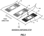
- FIG. 3 is a diagram illustrating an adhesive disposing step.
- FIG. 4 is a diagram illustrating an RFID inlay cutting step.
- FIG. 5 is a diagram illustrating an RFID inlay disposing step.
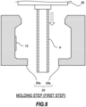
- FIG. 6 is a diagram illustrating a first step in a molding step.
- FIG. 7 is a diagram illustrating a second step in the molding step.
- FIG. 8 is a diagram illustrating a third step in the molding step.
- the adhesive disposing step is a step of laminating an elongated film 14A formed of the thermoplastic adhesive 14 on an RFID inlay continuous body 10A in which a plurality of RFID inlays 10 are connected while feeding the RFID inlay continuous body 10A and the film 14A.
- the film 14A is provided on a surface of the RFID inlay 10 on which the IC chip 13 is disposed.
- the film 14A is temporarily attached to the RFID inlay continuous body 10A by being pressurized by a pressure device (not shown) such as a pressure roller while being laminated on the RFID inlay continuous body 10A.
- the film 14A may be temporarily attached to the RFID inlay continuous body 10A using an adhesive or a binder, or may be temporarily attached using induction heating using molding pressure, high frequency, and the like in addition to pressurization.
- the RFID inlay continuous body 10A can be stored in a roll shape before and after the adhesive disposing step. Therefore, the degree of freedom in step design is increased, and the management of the RFID inlay continuous body 10A is also facilitated.
- the adhesive disposing step may be a step of applying the liquid thermoplastic adhesive 14 to the RFID inlay continuous body 10A.
- the RFID inlay cutting step is a step of cutting out a single RFID inlay 10 from the RFID inlay continuous body 10A on which the film 14A is laminated.
- the order of the adhesive disposing step and the RFID inlay cutting step may be switched. That is, a single RFID inlay 10 may be cut out from the RFID inlay continuous body 10A, and then the thermoplastic adhesive 14 may be applied to the single RFID inlay 10.
- the RFID inlay disposing step is a step of disposing the RFID inlay 10 on an inner surface of a mold 20 for molding the container 100.
- the mold 20 shown in FIGS. 5 to 8 is configured to compatible with blow molding.
- the container 100 may be molded by injection molding.
- the mold 20 is a metal mold.
- the mold 20 may not be made of metal as long as the mold 20 can form the container 100.
- the mold 20 includes a first mold 20a and a second mold 20b.
- the RFID inlay 10 is disposed on an inner surface of the first mold 20a.
- the RFID inlay 10 may be disposed on an inner surface of the second mold 20b.
- the RFID inlay 10 As a method for disposing the RFID inlay 10 on the inner surface of the mold 20, for example, it is possible to adhere the RFID inlay 10 to the inner surface of the mold 20 with a temporary adhesive.
- the mold 20 may be provided with a hole for venting air, and the RFID inlay 10 may be disposed on the inner surface of the mold 20 using a vacuum effect.
- the RFID inlay 10 is disposed on the inner surface of the mold 20 with the film 14A exposed. That is, a surface of the RFID inlay 10 on which the IC chip 13 is disposed is positioned closer to an inner space of the mold 20, and a flat surface of the RFID inlay 10 on which components are not disposed is positioned closer to the inner surface of the mold 20. Thus, the RFID inlay 10 can be stably disposed on the inner surface of the mold 20.
- the molding step is a step of molding the container 100 using the mold 20, and includes a first step shown in FIG. 6 , a second step shown in FIG. 7 , and a third step shown in FIG. 8 .
- a parison P which is a heated and melted cylindrical material, is supplied from a head 30 to the mold 20.
- the first mold 20a and the second mold 20b are brought into close contact with each other, and high-pressure air is blown into the parison P from a blow pin 31 inserted into the parison P.
- the parison P expands due to the internal pressure and is pressed against the inner surface of the mold 20 and molded into the shape of the container 100.
- the film 14A formed of the thermoplastic adhesive 14 melts when the high-temperature material comes into contact with the RFID inlay 10 disposed on the inner surface of the mold 20.
- the RFID inlay 10 and the material of the container 100 are adhered.
- the RFID inlay 10 Since the components of the RFID inlay 10 and the material of the container 100 are different materials, the RFID inlay 10 is easily peeled off from the container 100 simply by molding the RFID inlay 10 integrally with the heated material.
- thermoplastic adhesive 14 it is possible to ensure the adhesive strength between the components of the RFID inlay 10, in particular, the RFID antenna 12 made of metal and the material (resin) of the container 100.
- the thermoplastic adhesive 14 has a melting point lower than that of the material of the container 100 so as to melt by the heat transferred from the material.
- the melting point of the thermoplastic adhesive 14 is preferably lower than 160°C.
- the melting point of the thermoplastic adhesive 14 is preferably lower than 120°C.
- the temperature of the material of the container 100 when the container 100 is in contact with the RFID inlay 10 is lower than the melting point and higher than a softening point. Therefore, when the container 100 is molded by blow molding, the melting point of the thermoplastic adhesive 14 is preferably lower than the softening point of the material of the container 100. Thus, the thermoplastic adhesive 14 can be melted more reliably.
- the substrate 11 of the RFID inlay 10 is preferably a paper substrate having a lower thermal conductivity than resin or the like. Accordingly, the heat transferred from the material to the thermoplastic adhesive 14 can be prevented from being further transferred from the substrate 11 to the mold 20. That is, since the substrate 11 can function as a heat-insulating material, the thermoplastic adhesive 14 can be more easily melted.
- the RFID inlay 10 When the parison P is pressed against the mold 20 by the high-pressure air, the RFID inlay 10 is also pressed against the mold 20 via the parison P. In contrast, in the present embodiment, the RFID inlay 10 is disposed in the mold 20 such that the surface on which the IC chip 13 is disposed is positioned closer to the inner space of the mold 20.
- the IC chip 13 only comes into contact with the heated and softened material (parison P). Therefore, it is possible to prevent the IC chip 13 from being damaged by a strong force applied thereto when the container 100 is molded.
- the film 14A When the film 14A is laminated on the RFID inlay 10, the film 14A may be prevented from being laminated on the IC chip 13 by, for example, cutting out a portion corresponding to the IC chip 13. This can further reduce the force applied to the IC chip 13 when the container 100 is molded.
- the first mold 20a and the second mold 20b are separated, the container 100 is taken out from the mold 20, and an unnecessary gate portion 100b is cut off. Thus, the container 100 provided with the RFID inlay 10 is completed.
- the container 100 after molding cools and contracts. Since the components of the RFID inlay 10 and the material of the container 100 have different coefficients of thermal expansion, if the adhesive strength between the material of the container 100 and the components of the RFID inlay 10 is insufficient, the components of the RFID inlay 10 may be peeled off from the material due to the strain generated when the container 100 contracts.
- thermoplastic adhesive 14 it is possible to ensure the adhesive strength between the components of the RFID inlay 10, in particular, the RFID antenna 12 made of metal and the material of the container 100.
- the RFID inlay 10 is disposed on the inner surface of the mold 20. Therefore, even if the RFID inlay 10 is integrally molded with the container 100, the surface of the RFID inlay 10 that is not adhered to the material of the container 100 is open to the outside. Thus, the concentration of strain on the RFID inlay 10 when the container 100 contracts is reduced. Therefore, it is possible to prevent the components of the RFID inlay 10 from being damaged or deformed.
- the RFID inlay 10 is flush with the substrate 11 of the RFID inlay 10, as described above.
- the RFID inlay 10 can be prevented from being caught and peeled off or being damaged.
- the container manufacturing method includes the RFID inlay disposing step of disposing the RFID inlay 10 provided with the thermoplastic adhesive 14 on the inner surface of the mold 20 with the thermoplastic adhesive 14 exposed, and the molding step of supplying the heated material to the mold 20 and molding the container 100 provided with the RFID inlay 10 on the outer surface 100a via the thermoplastic adhesive 14.
- the RFID inlay 10 and the material of the container 100 are adhered by the thermoplastic adhesive 14 in contact with the heated material.
- the surface of the RFID inlay 10 that is not adhered to the material of the container 100 is open to the outside. Therefore, the concentration of strain on the RFID inlay 10 when the container 100 contracts is reduced. Therefore, it is possible to manufacture the container 100 provided with the RFID inlay 10 by the in-mold molding while reducing the influence on the performance of the RFID inlay 10.
- thermoplastic adhesive 14 is provided on the surface of the RFID inlay 10 on which the IC chip 13 is disposed.
- the RFID inlay 10 is disposed in the mold 20 such that the surface on which the IC chip 13 is disposed is positioned closer to the inner space of the mold 20. Therefore, when the container 100 is molded, the IC chip 13 only comes into contact with the heated and softened material. Therefore, it is possible to prevent the IC chip 13 from being damaged by a strong force applied thereto when the container 100 is molded.
- the melting point of the thermoplastic adhesive 14 is lower than the melting point of the material of the container 100.
- thermoplastic adhesive 14 melts when the high-temperature material comes into contact with the RFID inlay 10 disposed on the inner surface of the mold 20.
- the RFID inlay 10 and the material of the container 100 are adhered. Therefore, it is not necessary to separately provide a step of melting the thermoplastic adhesive 14.
- the melting point of the thermoplastic adhesive 14 is lower than the softening point of the material of the container 100.
- thermoplastic adhesive 14 can be melted more reliably.
- the RFID inlay 10 includes the substrate 11 made of paper, the RFID antenna 12 provided on the substrate 11, and the IC chip 13.
- the substrate 11 can function as a heat-insulating material, the thermoplastic adhesive 14 can be more easily melted.
- the RFID antenna 12 is made of metal, and the container 100 is made of resin.
- the adhesive strength can be secured by using the thermoplastic adhesive 14.
- the container manufacturing method includes, prior to the RFID inlay disposing step, the adhesive disposing step of laminating the film 14A formed of the thermoplastic adhesive 14 on the RFID inlay continuous body 10A in which the RFID inlays 10 are connected.
- the RFID inlay continuous body 10A can be stored in a roll shape before and after the adhesive disposing step. Therefore, the degree of freedom in step design is increased, and the management of the RFID inlay continuous body 10A is also facilitated.
- the container 100 can be molded by blow molding.
- blow molding can be used for the container 100 which is suitable for molding by blow molding.
- the container 100 can be molded by injection molding.
- injection molding can be used for the container 100 which is suitable for molding by injection molding.
- the material of the container 100 is resin
- the material of the container 100 may be glass.
- the container 100 is molded by blow molding in the molding step.
- thermoplastic adhesive 14 may be provided on the surface of the RFID inlay 10 on which the IC chip 13 is disposed.
- the thermoplastic adhesive 14 may be provided on the surface of the RFID inlay 10 opposite to the surface on which the IC chip 13 is disposed.
- the RFID inlay 10 is disposed in the mold 20 such that the surface on which the IC chip 13 is disposed faces the inner surface of the mold 20.
- the thermoplastic adhesive 14 may be provided on both surfaces of the RFID inlay 10.
- the RFID inlay 10 may be disposed on the inner surface of the mold 20 with either surface facing the inner surface of the mold 20.
Landscapes
- Engineering & Computer Science (AREA)
- Mechanical Engineering (AREA)
- Manufacturing & Machinery (AREA)
- Blow-Moulding Or Thermoforming Of Plastics Or The Like (AREA)
- Details Of Rigid Or Semi-Rigid Containers (AREA)
- Injection Moulding Of Plastics Or The Like (AREA)
Abstract
Description
- The present invention relates to a container manufacturing method.
-
JP 2009-73518 A - In the technique described above, the IC tag, that is, a radio frequency identification (RFID) inlay is entirely covered with resin. Therefore, when the container and the covered resin integrated with the container contract after molding, strain is likely to concentrate on components of the RFID inlay having a coefficient of thermal expansion different from that of the resin. As a result, for example, an RFID antenna made of metal may be damaged or deformed, which may cause the performance of the RFID inlay to deteriorate.
- The present invention has been made in view of the above technical problems, and an object of the present invention is to make it possible to manufacture a container provided with an RFID inlay by in-mold molding while reducing the influence on the performance of the RFID inlay.
- According to one aspect of the present invention, a container manufacturing method includes an RFID inlay disposing step of disposing an RFID inlay provided with a thermoplastic adhesive on an inner surface of a mold with the thermoplastic adhesive exposed, and a molding step of supplying a heated material to the mold and molding a container provided with the RFID inlay on an outer surface thereof via the thermoplastic adhesive.
- According to the above aspect, the RFID inlay and a material of the container are adhered by the thermoplastic adhesive in contact with the heated material. After the molding of the container, a surface of the RFID inlay that is not adhered to the material of the container is open to the outside. Therefore, the concentration of strain on the RFID inlay when the container contracts is reduced. Therefore, it is possible to manufacture a container provided with an RFID inlay by in-mold molding while reducing the influence on the performance of the RFID inlay.
-
- [
FIG. 1] FIG. 1 is an external view of a container manufactured by a container manufacturing method according to an embodiment of the present invention. - [
FIG. 2] FIG. 2 is a partial cross-sectional view partially showing a cross section taken along line II-II ofFIG. 1 . - [
FIG. 3] FIG. 3 is a diagram illustrating an adhesive disposing step. - [
FIG. 4] FIG. 4 is a diagram illustrating an RFID inlay cutting step. - [
FIG. 5] FIG. 5 is a diagram illustrating an RFID inlay disposing step. - [
FIG. 6] FIG. 6 is a diagram illustrating a first step in a molding step. - [
FIG. 7] FIG. 7 is a diagram illustrating a second step in the molding step. - [
FIG. 8] FIG. 8 is a diagram illustrating a third step in the molding step. - Hereinafter, a container manufacturing method and a
container 100 manufactured using the container manufacturing method according to an embodiment of the present invention will be described with reference to the accompanying drawings. - First, the
container 100 will be described with reference toFIGS. 1 and 2 . -
FIG. 1 is an external view of thecontainer 100.FIG. 2 is a partial cross-sectional view partially showing a cross-section taken along line II-II ofFIG. 1 . - The
container 100 is used for, for example, blood collection or a specimen test. A shape of thecontainer 100 is not limited to the shape shown inFIG. 1 and may be, for example, a test tube shape. - In the present embodiment, the
container 100 is made of resin. As a material for thecontainer 100, for example, polypropylene, polyethylene, and polyethylene terephthalate can be used. - As shown in
FIGS. 1 and 2 , thecontainer 100 includes a radio frequency identification (RFID)inlay 10. In thecontainer 100, theRFID inlay 10 can be used to manage thecontainer 100 itself and contents therein. - The
RFID inlay 10 includes asubstrate 11, anRFID antenna 12 provided on thesubstrate 11, and anIC chip 13 connected to theRFID antenna 12, and information is read from/written to theIC chip 13 through non-contact communication with a reader/writer. - The
RFID inlay 10 is adhered to the material of thecontainer 100 with athermoplastic adhesive 14 so that thesubstrate 11 is exposed to the outside on anouter surface 100a of thecontainer 100. As shown inFIG. 2 , thecontainer 100 is formed such that theouter surface 100a is flush with thesubstrate 11 of theRFID inlay 10. - As the
thermoplastic adhesive 14, it is preferable to adopt an adhesive that is a solid substance that melts by heat or the like and hardens when cooled, and can chemically bond or mutually diffuse bond the material of thecontainer 100, thesubstrate 11, and theRFID antenna 12 made of metal. Specifically, for example, a thermoplastic polyurethane adhesive and a thermoplastic polyester adhesive can be used. - In the present embodiment, the
substrate 11 is a substrate made of paper (hereinafter, referred to as a paper substrate). As the paper substrate, high-quality paper, medium-quality paper, or coated paper formed using the high-quality paper and the medium-quality paper can be used. - As the
substrate 11, in addition to the paper substrate, a single resin film such as polyvinyl chloride, polyethylene terephthalate, polypropylene, polyethylene, or polyethylene naphthalate, or a multilayer film formed by laminating a plurality of these resin films can be used. - In a case where the paper substrate is used as the
substrate 11, when theIC chip 13 is mounted on theRFID antenna 12 formed on thesubstrate 11 using an anisotropic conductive material, the adhesive strength between theIC chip 13 and thesubstrate 11 can be increased. - The
RFID antenna 12 constitutes a dipole antenna. - In the present embodiment, the
RFID antenna 12 is designed to have an antenna length and an antenna line width that support a UHF band (300 MHz to 3 GHz, particularly 860 MHz to 960 MHz). - The
RFID antenna 12 may be designed to support an HF band (3 MHz to 30 MHz, particularly around 13.56 MHz). When theRFID antenna 12 supports the HF band, antenna patterns may be disposed on both surfaces of thesubstrate 11. - The
RFID antenna 12 is adhered to thesubstrate 11 with a binder such as an acrylic binder, a urethane binder, a silicone binder, or a rubber binder. - The
RFID antenna 12 is formed of metal foil. Examples of the metal applicable to theRFID antenna 12 include copper and aluminum. From the viewpoint of reducing manufacturing costs, it is preferable to use aluminum foil. - From the viewpoint of a thickness of the
entire RFID inlay 10, the manufacturing costs, and the like, a thickness of the metal foil is preferably 3 pm or more and 25 pm or less. - The
RFID antenna 12 may be formed by applying a paste containing metal powder, or may be formed by printing a conductive material using inkjet. - The
IC chip 13 is a semi-conductor package designed to be able to communicate with the reader/writer. In the present embodiment, theIC chip 13 supports the UHF band. TheIC chip 13 may be designed to support the HF band together with theRFID antenna 12. - The
IC chip 13 is electrically and mechanically connected to theRFID antenna 12 with the anisotropic conductive material such as an anisotropic conductive adhesive or an anisotropic conductive film. - In the anisotropic conductive material, a conductive filler prepared with a predetermined particle size is mixed in binder resin as an adhesive component. The anisotropic conductive material can electrically and mechanically connect the
RFID antenna 12 and theIC chip 13 by processing such as thermocompression bonding or ultraviolet curing. - As described above, when the
container 100 is used for blood collection or the like, radio waves in the UHF band are attenuated or become unstable when glass or moisture intervenes. Therefore, as theRFID inlay 10, it is preferable to use a moisture-resistant inlay capable of ensuring communication characteristics even when a liquid is contained in thecontainer 100. As the moisture-resistant inlay, existing products available on the market may be used. - When the
container 100 is used for medical applications such as blood collection, it is preferable to use a sterilizable inlay as theRFID inlay 10. As the sterilizable inlay, existing products available on the market may be used. - Next, a container manufacturing method for manufacturing the
container 100 will be described with reference toFIGS. 3 to 8 . -
FIG. 3 is a diagram illustrating an adhesive disposing step.FIG. 4 is a diagram illustrating an RFID inlay cutting step.FIG. 5 is a diagram illustrating an RFID inlay disposing step.FIG. 6 is a diagram illustrating a first step in a molding step.FIG. 7 is a diagram illustrating a second step in the molding step.FIG. 8 is a diagram illustrating a third step in the molding step. - First, the adhesive disposing step will be described with reference to
FIG. 3 . - As shown in
FIG. 3 , the adhesive disposing step is a step of laminating anelongated film 14A formed of thethermoplastic adhesive 14 on an RFID inlaycontinuous body 10A in which a plurality of RFID inlays 10 are connected while feeding the RFID inlaycontinuous body 10A and thefilm 14A. - In the present embodiment, the
film 14A is provided on a surface of theRFID inlay 10 on which theIC chip 13 is disposed. - The
film 14A is temporarily attached to the RFID inlaycontinuous body 10A by being pressurized by a pressure device (not shown) such as a pressure roller while being laminated on the RFID inlaycontinuous body 10A. Thefilm 14A may be temporarily attached to the RFID inlaycontinuous body 10A using an adhesive or a binder, or may be temporarily attached using induction heating using molding pressure, high frequency, and the like in addition to pressurization. - As described above, in the present embodiment, since the
film 14A is laminated on the RFID inlaycontinuous body 10A, the RFID inlaycontinuous body 10A can be stored in a roll shape before and after the adhesive disposing step. Therefore, the degree of freedom in step design is increased, and the management of the RFID inlaycontinuous body 10A is also facilitated. - The adhesive disposing step may be a step of applying the liquid thermoplastic adhesive 14 to the RFID inlay
continuous body 10A. - Next, the RFID inlay cutting step will be described with reference to
FIG. 4 . - As shown in
FIG. 4 , the RFID inlay cutting step is a step of cutting out asingle RFID inlay 10 from the RFID inlaycontinuous body 10A on which thefilm 14A is laminated. - The order of the adhesive disposing step and the RFID inlay cutting step may be switched. That is, a
single RFID inlay 10 may be cut out from the RFID inlaycontinuous body 10A, and then thethermoplastic adhesive 14 may be applied to thesingle RFID inlay 10. - Next, the RFID inlay disposing step will be described with reference to
FIG. 5 . - As shown in
FIG. 5 , the RFID inlay disposing step is a step of disposing theRFID inlay 10 on an inner surface of amold 20 for molding thecontainer 100. - In the present embodiment, a case where the
container 100 is molded by blow molding will be described. Therefore, themold 20 shown inFIGS. 5 to 8 is configured to compatible with blow molding. However, thecontainer 100 may be molded by injection molding. - In the present embodiment, the
mold 20 is a metal mold. However, themold 20 may not be made of metal as long as themold 20 can form thecontainer 100. - The
mold 20 includes afirst mold 20a and asecond mold 20b. InFIG. 5 , theRFID inlay 10 is disposed on an inner surface of thefirst mold 20a. However, theRFID inlay 10 may be disposed on an inner surface of thesecond mold 20b. - As a method for disposing the
RFID inlay 10 on the inner surface of themold 20, for example, it is possible to adhere theRFID inlay 10 to the inner surface of themold 20 with a temporary adhesive. In addition, themold 20 may be provided with a hole for venting air, and theRFID inlay 10 may be disposed on the inner surface of themold 20 using a vacuum effect. - As shown in a partially enlarged view in
FIG. 5 , theRFID inlay 10 is disposed on the inner surface of themold 20 with thefilm 14A exposed. That is, a surface of theRFID inlay 10 on which theIC chip 13 is disposed is positioned closer to an inner space of themold 20, and a flat surface of theRFID inlay 10 on which components are not disposed is positioned closer to the inner surface of themold 20. Thus, theRFID inlay 10 can be stably disposed on the inner surface of themold 20. - Next, the molding step will be described with reference to
FIGS. 6 to 8 . - The molding step is a step of molding the
container 100 using themold 20, and includes a first step shown inFIG. 6 , a second step shown inFIG. 7 , and a third step shown inFIG. 8 . - In the first step, as shown in
FIG. 6 , a parison P, which is a heated and melted cylindrical material, is supplied from ahead 30 to themold 20. - In the second step, the
first mold 20a and thesecond mold 20b are brought into close contact with each other, and high-pressure air is blown into the parison P from ablow pin 31 inserted into the parison P. - Thus, the parison P expands due to the internal pressure and is pressed against the inner surface of the
mold 20 and molded into the shape of thecontainer 100. - At this time, the
film 14A formed of the thermoplastic adhesive 14 melts when the high-temperature material comes into contact with theRFID inlay 10 disposed on the inner surface of themold 20. Thus, theRFID inlay 10 and the material of thecontainer 100 are adhered. - Since the components of the
RFID inlay 10 and the material of thecontainer 100 are different materials, theRFID inlay 10 is easily peeled off from thecontainer 100 simply by molding theRFID inlay 10 integrally with the heated material. - In the present embodiment, by using the
thermoplastic adhesive 14, it is possible to ensure the adhesive strength between the components of theRFID inlay 10, in particular, theRFID antenna 12 made of metal and the material (resin) of thecontainer 100. - The
thermoplastic adhesive 14 has a melting point lower than that of the material of thecontainer 100 so as to melt by the heat transferred from the material. For example, when the material of thecontainer 100 is polypropylene, since polypropylene has a melting point of 160°C to 170°C, the melting point of thethermoplastic adhesive 14 is preferably lower than 160°C. For example, when the material of thecontainer 100 is polyethylene, since polypropylene has a melting point of 120°C to 140°C, the melting point of thethermoplastic adhesive 14 is preferably lower than 120°C. - In blow molding, the temperature of the material of the
container 100 when thecontainer 100 is in contact with theRFID inlay 10 is lower than the melting point and higher than a softening point. Therefore, when thecontainer 100 is molded by blow molding, the melting point of thethermoplastic adhesive 14 is preferably lower than the softening point of the material of thecontainer 100. Thus, the thermoplastic adhesive 14 can be melted more reliably. - Since the
mold 20 is normally cooled, when the material of thecontainer 100 comes into contact with themold 20, the temperature of the material rapidly decreases. Therefore, in order to more reliably transfer the heat of the material to thethermoplastic adhesive 14, thesubstrate 11 of theRFID inlay 10 is preferably a paper substrate having a lower thermal conductivity than resin or the like. Accordingly, the heat transferred from the material to the thermoplastic adhesive 14 can be prevented from being further transferred from thesubstrate 11 to themold 20. That is, since thesubstrate 11 can function as a heat-insulating material, the thermoplastic adhesive 14 can be more easily melted. - When the parison P is pressed against the
mold 20 by the high-pressure air, theRFID inlay 10 is also pressed against themold 20 via the parison P. In contrast, in the present embodiment, theRFID inlay 10 is disposed in themold 20 such that the surface on which theIC chip 13 is disposed is positioned closer to the inner space of themold 20. - Accordingly, when the
container 100 is molded, theIC chip 13 only comes into contact with the heated and softened material (parison P). Therefore, it is possible to prevent theIC chip 13 from being damaged by a strong force applied thereto when thecontainer 100 is molded. - When the
film 14A is laminated on theRFID inlay 10, thefilm 14A may be prevented from being laminated on theIC chip 13 by, for example, cutting out a portion corresponding to theIC chip 13. This can further reduce the force applied to theIC chip 13 when thecontainer 100 is molded. - In the third step, the
first mold 20a and thesecond mold 20b are separated, thecontainer 100 is taken out from themold 20, and anunnecessary gate portion 100b is cut off. Thus, thecontainer 100 provided with theRFID inlay 10 is completed. - The
container 100 after molding cools and contracts. Since the components of theRFID inlay 10 and the material of thecontainer 100 have different coefficients of thermal expansion, if the adhesive strength between the material of thecontainer 100 and the components of theRFID inlay 10 is insufficient, the components of theRFID inlay 10 may be peeled off from the material due to the strain generated when thecontainer 100 contracts. - In contrast, in the present embodiment, as described above, by using the
thermoplastic adhesive 14, it is possible to ensure the adhesive strength between the components of theRFID inlay 10, in particular, theRFID antenna 12 made of metal and the material of thecontainer 100. - In the present embodiment, the
RFID inlay 10 is disposed on the inner surface of themold 20. Therefore, even if theRFID inlay 10 is integrally molded with thecontainer 100, the surface of theRFID inlay 10 that is not adhered to the material of thecontainer 100 is open to the outside. Thus, the concentration of strain on theRFID inlay 10 when thecontainer 100 contracts is reduced. Therefore, it is possible to prevent the components of theRFID inlay 10 from being damaged or deformed. - In addition, by disposing the
RFID inlay 10 on the inner surface of themold 20, theouter surface 100a of thecontainer 100 is flush with thesubstrate 11 of theRFID inlay 10, as described above. Thus, when thecontainer 100 is handled, theRFID inlay 10 can be prevented from being caught and peeled off or being damaged. - Hereinafter, functions and effects of the container manufacturing method according to the present embodiment will be collectively described.
- The container manufacturing method includes the RFID inlay disposing step of disposing the
RFID inlay 10 provided with thethermoplastic adhesive 14 on the inner surface of themold 20 with the thermoplastic adhesive 14 exposed, and the molding step of supplying the heated material to themold 20 and molding thecontainer 100 provided with theRFID inlay 10 on theouter surface 100a via thethermoplastic adhesive 14. - Accordingly, the
RFID inlay 10 and the material of thecontainer 100 are adhered by the thermoplastic adhesive 14 in contact with the heated material. After thecontainer 100 is molded, the surface of theRFID inlay 10 that is not adhered to the material of thecontainer 100 is open to the outside. Therefore, the concentration of strain on theRFID inlay 10 when thecontainer 100 contracts is reduced. Therefore, it is possible to manufacture thecontainer 100 provided with theRFID inlay 10 by the in-mold molding while reducing the influence on the performance of theRFID inlay 10. - The
thermoplastic adhesive 14 is provided on the surface of theRFID inlay 10 on which theIC chip 13 is disposed. - Accordingly, the
RFID inlay 10 is disposed in themold 20 such that the surface on which theIC chip 13 is disposed is positioned closer to the inner space of themold 20. Therefore, when thecontainer 100 is molded, theIC chip 13 only comes into contact with the heated and softened material. Therefore, it is possible to prevent theIC chip 13 from being damaged by a strong force applied thereto when thecontainer 100 is molded. - The melting point of the
thermoplastic adhesive 14 is lower than the melting point of the material of thecontainer 100. - Accordingly, the thermoplastic adhesive 14 melts when the high-temperature material comes into contact with the
RFID inlay 10 disposed on the inner surface of themold 20. Thus, theRFID inlay 10 and the material of thecontainer 100 are adhered. Therefore, it is not necessary to separately provide a step of melting thethermoplastic adhesive 14. - The melting point of the
thermoplastic adhesive 14 is lower than the softening point of the material of thecontainer 100. - Accordingly, when the
container 100 is molded by blow molding, the thermoplastic adhesive 14 can be melted more reliably. - The
RFID inlay 10 includes thesubstrate 11 made of paper, theRFID antenna 12 provided on thesubstrate 11, and theIC chip 13. - Accordingly, since the
substrate 11 can function as a heat-insulating material, the thermoplastic adhesive 14 can be more easily melted. - The
RFID antenna 12 is made of metal, and thecontainer 100 is made of resin. - As described above, even when the
RFID antenna 12 and thecontainer 100 are made of different materials, the adhesive strength can be secured by using thethermoplastic adhesive 14. - The container manufacturing method includes, prior to the RFID inlay disposing step, the adhesive disposing step of laminating the
film 14A formed of thethermoplastic adhesive 14 on the RFID inlaycontinuous body 10A in which the RFID inlays 10 are connected. - Accordingly, the RFID inlay
continuous body 10A can be stored in a roll shape before and after the adhesive disposing step. Therefore, the degree of freedom in step design is increased, and the management of the RFID inlaycontinuous body 10A is also facilitated. - In the molding step, the
container 100 can be molded by blow molding. - Accordingly, blow molding can be used for the
container 100 which is suitable for molding by blow molding. - In the molding step, the
container 100 can be molded by injection molding. - Accordingly, injection molding can be used for the
container 100 which is suitable for molding by injection molding. - While an embodiment of the invention has been described, the embodiment is merely one of application examples of the invention, and does not intend to limit a technical scope of the invention to a specific configuration according to the embodiment.
- For example, in the above embodiment, the case where the material of the
container 100 is resin has been described. However, the material of thecontainer 100 may be glass. When the material of thecontainer 100 is glass, thecontainer 100 is molded by blow molding in the molding step. - In the above embodiment, the case where the
thermoplastic adhesive 14 is provided on the surface of theRFID inlay 10 on which theIC chip 13 is disposed has been described. However, thethermoplastic adhesive 14 may be provided on the surface of theRFID inlay 10 opposite to the surface on which theIC chip 13 is disposed. In this case, in the RFID inlay disposing step, theRFID inlay 10 is disposed in themold 20 such that the surface on which theIC chip 13 is disposed faces the inner surface of themold 20. Thethermoplastic adhesive 14 may be provided on both surfaces of theRFID inlay 10. In this case, theRFID inlay 10 may be disposed on the inner surface of themold 20 with either surface facing the inner surface of themold 20. - The present application makes a priority claim based on
Japanese Patent Application No. 2021-155705 filed in the Japan Patent Office on September 24, 2021
Claims (9)
- A container manufacturing method comprising:an RFID inlay disposing step of disposing an RFID inlay provided with a thermoplastic adhesive on an inner surface of a mold with the thermoplastic adhesive exposed; anda molding step of supplying a heated material to the mold and molding a container provided with the RFID inlay on an outer surface thereof via the thermoplastic adhesive.
- The container manufacturing method according to claim 1, wherein
the thermoplastic adhesive is provided on a surface of the RFID inlay on which an IC chip is disposed. - The container manufacturing method according to claim 1 or 2, wherein
a melting point of the thermoplastic adhesive is lower than a melting point of the material. - The container manufacturing method according to claim 1 or 2, wherein
a melting point of the thermoplastic adhesive is lower than a softening point of the material. - The container manufacturing method according to claim 2, wherein
the RFID inlay includes a substrate made of paper, an RFID antenna provided on the substrate, and the IC chip. - The container manufacturing method according to claim 5, wherein
the RFID antenna is made of metal, and the container is made of resin. - The container manufacturing method according to any one of claims 1 to 6, further comprising:
before the RFID inlay disposing step, an adhesive disposing step of laminating a film formed of the thermoplastic adhesive on an RFID inlay continuous body in which the RFID inlays are connected. - The container manufacturing method according to any one of claims 1 to 7, wherein
in the molding step, the container is molded by blow molding. - The container manufacturing method according to any one of claims 1 to 7, wherein
in the molding step, the container is molded by injection molding.
Applications Claiming Priority (2)
| Application Number | Priority Date | Filing Date | Title |
|---|---|---|---|
| JP2021155705A JP7796498B2 (en) | 2021-09-24 | 2021-09-24 | Container manufacturing method |
| PCT/JP2022/034858 WO2023048106A1 (en) | 2021-09-24 | 2022-09-16 | Container manufacturing method |
Publications (2)
| Publication Number | Publication Date |
|---|---|
| EP4406722A1 true EP4406722A1 (en) | 2024-07-31 |
| EP4406722A4 EP4406722A4 (en) | 2025-01-01 |
Family
ID=85719475
Family Applications (1)
| Application Number | Title | Priority Date | Filing Date |
|---|---|---|---|
| EP22872860.6A Pending EP4406722A4 (en) | 2021-09-24 | 2022-09-16 | Container manufacturing method |
Country Status (4)
| Country | Link |
|---|---|
| US (1) | US20240359388A1 (en) |
| EP (1) | EP4406722A4 (en) |
| JP (1) | JP7796498B2 (en) |
| WO (1) | WO2023048106A1 (en) |
Families Citing this family (1)
| Publication number | Priority date | Publication date | Assignee | Title |
|---|---|---|---|---|
| JPWO2025052688A1 (en) | 2023-09-07 | 2025-03-13 |
Family Cites Families (19)
| Publication number | Priority date | Publication date | Assignee | Title |
|---|---|---|---|---|
| CA1340219C (en) * | 1988-04-06 | 1998-12-15 | Tadahiko Katsura | Labelled vessel and process for preparation thereof |
| JP3142602B2 (en) * | 1991-07-03 | 2001-03-07 | 株式会社ユポ・コーポレーション | Method for producing hollow container with label attached |
| JP3051209B2 (en) * | 1991-07-25 | 2000-06-12 | 王子油化合成紙株式会社 | Manufacturing method of labeled container |
| FI117331B (en) * | 2001-07-04 | 2006-09-15 | Rafsec Oy | Method of manufacturing an injection molded product |
| US20050068182A1 (en) * | 2003-09-30 | 2005-03-31 | Dunlap Richard L. | Application of radio frequency identification |
| US7528727B2 (en) * | 2005-08-04 | 2009-05-05 | Sonoco Development, Inc. | Tracking device for polymeric packaging |
| JP2007128384A (en) * | 2005-11-07 | 2007-05-24 | Navitas Co Ltd | Resin molded product with IC tag |
| US20100052215A1 (en) * | 2006-02-16 | 2010-03-04 | University Of Florida Research Foundation , Inc. | Radio Frequency Identification Device for Plastic Container and Method of Manufacture of Same |
| DE502007006894D1 (en) * | 2006-06-29 | 2011-05-19 | Ksw Microtec Ag | METHOD FOR PRODUCING A CONTAINER AND A CONTAINER FOR STORING AND TRANSPORTING ITEMS AND BULBS |
| CN101140633B (en) * | 2006-09-05 | 2010-09-01 | 黄胜昌 | Radio frequency identification in-mold forming label |
| US7922961B2 (en) * | 2006-11-10 | 2011-04-12 | Rexam Healthcare Packaging Inc. | Molded plastic container having insert-molded insert and method of manufacture |
| JP5087354B2 (en) * | 2007-09-20 | 2012-12-05 | アイセロ化学株式会社 | Clean container manufacturing method |
| US8094027B2 (en) * | 2007-12-19 | 2012-01-10 | Abbott Laboratories | Method for molding an object containing a radio frequency identification tag |
| JP5565648B2 (en) * | 2008-10-31 | 2014-08-06 | 株式会社吉野工業所 | Injection molded product with IC tag |
| GB2498775A (en) * | 2012-01-27 | 2013-07-31 | Innovia Films Ltd | In-mould labelling process |
| US20130240631A1 (en) * | 2012-03-15 | 2013-09-19 | Supreme Technic Package Co., Ltd. | Container cap having identification function and its manufacturing method |
| US10479556B2 (en) * | 2017-09-21 | 2019-11-19 | Silgan Plastics Llc | Integrally, extrusion blow molded container, label and RFID tag |
| JP2021140670A (en) * | 2020-03-09 | 2021-09-16 | サトーホールディングス株式会社 | Manufacturing method of RFID inlay |
| JP2021155705A (en) | 2020-03-27 | 2021-10-07 | Agc株式会社 | Polyurethane resin, polyurethane resin precursor, polyoxyalkylene diol and method for producing the same, and composition and article |
-
2021
- 2021-09-24 JP JP2021155705A patent/JP7796498B2/en active Active
-
2022
- 2022-09-16 US US18/685,675 patent/US20240359388A1/en active Pending
- 2022-09-16 WO PCT/JP2022/034858 patent/WO2023048106A1/en not_active Ceased
- 2022-09-16 EP EP22872860.6A patent/EP4406722A4/en active Pending
Also Published As
| Publication number | Publication date |
|---|---|
| JP2023046872A (en) | 2023-04-05 |
| EP4406722A4 (en) | 2025-01-01 |
| WO2023048106A1 (en) | 2023-03-30 |
| US20240359388A1 (en) | 2024-10-31 |
| JP7796498B2 (en) | 2026-01-09 |
Similar Documents
| Publication | Publication Date | Title |
|---|---|---|
| US7730606B2 (en) | Manufacturing method for a wireless communication device and manufacturing apparatus | |
| US20060273180A1 (en) | RFID label assembly | |
| AU2005325736B2 (en) | Method of making memory cards by injection molding | |
| JP4770853B2 (en) | RFID tag and manufacturing method thereof | |
| JP2011518681A (en) | Method for forming object including radio frequency identification tag | |
| CN102449846B (en) | Wireless IC device and production method thereof | |
| US20240359388A1 (en) | Container manufacturing method | |
| US20240028861A1 (en) | Rfid label and method of using rfid label | |
| FI119401B (en) | Smart label web and process for its manufacture | |
| JP4579924B2 (en) | Production method of card having dual interface and microcircuit card obtained by the same method | |
| JP4433020B2 (en) | RFID tag and manufacturing method thereof | |
| JP4797281B2 (en) | IC tag inlet insert-in-mold molding method | |
| JPH11345299A (en) | Non-contact type IC card and manufacturing method thereof | |
| CN1918583B (en) | Electronic device | |
| CN111126541A (en) | Structure of RFID smart card and manufacturing method thereof | |
| CN115702073A (en) | Preform laminated body and laminated container | |
| WO2026028577A1 (en) | Resin molded body with built-in rfid inlay and method for manufacturing same | |
| JP2000322547A (en) | Non-contact IC card and method of manufacturing the same | |
| JPH10157354A (en) | Non-contact IC card and its manufacturing apparatus |
Legal Events
| Date | Code | Title | Description |
|---|---|---|---|
| STAA | Information on the status of an ep patent application or granted ep patent |
Free format text: STATUS: THE INTERNATIONAL PUBLICATION HAS BEEN MADE |
|
| PUAI | Public reference made under article 153(3) epc to a published international application that has entered the european phase |
Free format text: ORIGINAL CODE: 0009012 |
|
| STAA | Information on the status of an ep patent application or granted ep patent |
Free format text: STATUS: REQUEST FOR EXAMINATION WAS MADE |
|
| 17P | Request for examination filed |
Effective date: 20240227 |
|
| AK | Designated contracting states |
Kind code of ref document: A1 Designated state(s): AL AT BE BG CH CY CZ DE DK EE ES FI FR GB GR HR HU IE IS IT LI LT LU LV MC MK MT NL NO PL PT RO RS SE SI SK SM TR |
|
| A4 | Supplementary search report drawn up and despatched |
Effective date: 20241204 |
|
| DAV | Request for validation of the european patent (deleted) | ||
| DAX | Request for extension of the european patent (deleted) | ||
| RIC1 | Information provided on ipc code assigned before grant |
Ipc: C03B 9/30 20060101ALN20241128BHEP Ipc: B32B 9/00 20060101ALN20241128BHEP Ipc: B29L 31/00 20060101ALN20241128BHEP Ipc: B29C 49/04 20060101ALN20241128BHEP Ipc: B65D 25/20 20060101ALI20241128BHEP Ipc: B29C 45/14 20060101ALI20241128BHEP Ipc: B29C 49/20 20060101AFI20241128BHEP |
|
| RAP3 | Party data changed (applicant data changed or rights of an application transferred) |
Owner name: SATO CORPORATION |
|
| STAA | Information on the status of an ep patent application or granted ep patent |
Free format text: STATUS: EXAMINATION IS IN PROGRESS |
|
| 17Q | First examination report despatched |
Effective date: 20251223 |