EP4406503A1 - Chirurgisches navigationssystem mit handhabung von teilweise verborgenen markern - Google Patents
Chirurgisches navigationssystem mit handhabung von teilweise verborgenen markern Download PDFInfo
- Publication number
- EP4406503A1 EP4406503A1 EP23315014.3A EP23315014A EP4406503A1 EP 4406503 A1 EP4406503 A1 EP 4406503A1 EP 23315014 A EP23315014 A EP 23315014A EP 4406503 A1 EP4406503 A1 EP 4406503A1
- Authority
- EP
- European Patent Office
- Prior art keywords
- fiducial markers
- patterns
- criterion
- tot
- pattern
- Prior art date
- Legal status (The legal status is an assumption and is not a legal conclusion. Google has not performed a legal analysis and makes no representation as to the accuracy of the status listed.)
- Pending
Links
Images








Classifications
-
- A—HUMAN NECESSITIES
- A61—MEDICAL OR VETERINARY SCIENCE; HYGIENE
- A61B—DIAGNOSIS; SURGERY; IDENTIFICATION
- A61B34/00—Computer-aided surgery; Manipulators or robots specially adapted for use in surgery
- A61B34/20—Surgical navigation systems; Devices for tracking or guiding surgical instruments, e.g. for frameless stereotaxis
-
- A—HUMAN NECESSITIES
- A61—MEDICAL OR VETERINARY SCIENCE; HYGIENE
- A61B—DIAGNOSIS; SURGERY; IDENTIFICATION
- A61B34/00—Computer-aided surgery; Manipulators or robots specially adapted for use in surgery
- A61B34/30—Surgical robots
-
- A—HUMAN NECESSITIES
- A61—MEDICAL OR VETERINARY SCIENCE; HYGIENE
- A61B—DIAGNOSIS; SURGERY; IDENTIFICATION
- A61B34/00—Computer-aided surgery; Manipulators or robots specially adapted for use in surgery
- A61B34/20—Surgical navigation systems; Devices for tracking or guiding surgical instruments, e.g. for frameless stereotaxis
- A61B2034/2046—Tracking techniques
- A61B2034/2055—Optical tracking systems
-
- A—HUMAN NECESSITIES
- A61—MEDICAL OR VETERINARY SCIENCE; HYGIENE
- A61B—DIAGNOSIS; SURGERY; IDENTIFICATION
- A61B90/00—Instruments, implements or accessories specially adapted for surgery or diagnosis and not covered by any of the groups A61B1/00 - A61B50/00, e.g. for luxation treatment or for protecting wound edges
- A61B90/08—Accessories or related features not otherwise provided for
- A61B2090/0818—Redundant systems, e.g. using two independent measuring systems and comparing the signals
Definitions
- the invention is notably applicable to navigate a surgical tool during a surgical intervention.
- a surgical navigation system known from prior art comprises:
- the two optical sensors of the stereoscopic camera will give divergent information about the position of the corresponding fiducial marker.
- the data processor is configured to apply a criterion based on a root-mean-square (RMS) deviation to compare the information of the two optical sensors of the stereoscopic camera, so as to complete an image registration of the images captured by the stereoscopic camera.
- the image registration is completed as long as the image registration error (i.e. the RMS error) is below a threshold.
- the skilled person in the art is looking for a more reliable criterion than the RMS error on the positions of the partially-obscured fiducial marker, and having a relevant clinical meaning in order to improve the safety of the navigation system..
- one subject of the invention is a surgical navigation system, comprising:
- such a surgical navigation system makes it possible to reliably detect the presence of at least one partially-obscured fiducial marker by comparing poses of the reference zone (e.g. a tip of a surgical instrument), which have clinical significance. More specifically, the criterion applied in step d) compares the poses of the reference zone computed in step c) therebetween for the set of patterns.
- the reference zone e.g. a tip of a surgical instrument
- Another subject of the invention is a surgical navigation system, comprising:
- such a surgical navigation system makes it possible to reliably detect the presence of at least one partially-obscured fiducial marker by comparing poses of the reference zone (e.g. a tip of a surgical instrument), which have clinical significance. More specifically, the criterion applied in step d) compares the pose of the reference zone computed in step c'), with the poses of the reference zone computed in step c) for the set of patterns.
- the reference zone e.g. a tip of a surgical instrument
- the surgical navigation system according to the invention may include one or more of the following features.
- step e) gives more information than a simple presence detection. Indeed, step e) allows to locate N po partially-obscured fiducial markers when N po ⁇ M-3.
- Step e) cannot locate N po partially-obscured fiducial markers when N po > M-3. However, in this case, step e) gives information on the quantity of partially-obscured fiducial markers. More specifically, step e) cannot give the exact number of partially-obscured fiducial markers, but can give the information that N po > M-3.
- the data processor is further configured to perform steps:
- one advantage afforded is that of exploiting the information obtained in step e). More specifically, on the one hand, the location of the N po partially-obscured fiducial markers, when N po ⁇ M-3, makes it possible to reliably complete an image registration of the images captured by the stereoscopic camera. On the other hand, the presence of N po partially-obscured fiducial markers, when N po > M-3, switches off the surgical navigation for safety purpose.
- each pattern of the set generated in step b) is selected according to the positions of the corresponding M fiducial markers thereof with respect to each other.
- one advantage afforded is that of improving the reliability of the criterion applied in step d).
- the set of patterns generated in step b) satisfies a spread criterion that compares relative positions of the M fiducial markers for each pattern of the set, from the positions determined in step a); the spread criterion being designed to detect a minimal spatial spread between the M fiducial markers of a given pattern of the set.
- one advantage afforded is that of improving the reliability of the criterion applied in step d).
- each pattern of the set generated in step b) is selected according to the positions of the corresponding M fiducial markers thereof with respect to the stereoscopic camera.
- one advantage afforded is that of improving the reliability of the criterion applied in step d).
- the set of patterns generated in step b) satisfies a visibility criterion that compares visibility levels of the M fiducial markers between all patterns of the set, from the images captured by stereoscopic camera; the visibility criterion being designed to detect a minimal visibility level at which the M fiducial markers of a given pattern of the set are discerned by the stereoscopic camera within a predetermined margin of error.
- one advantage afforded is that of improving the reliability of the criterion applied in step d).
- the set of patterns generated in step b) satisfies both the spread criterion and the visibility criterion.
- one advantage afforded is that of maximizing the reliability of the criterion applied in step d).
- the data processor is configured to perform step b) by setting the integer M of fiducial markers to the integer that is equal to N tot - 1.
- the data processor is configured to perform step b) by:
- the data processor is configured to perform step: b 3 ) select a set of patterns, from patterns generated in step b 2 ), that satisfies the spread criterion.
- one advantage afforded is that of improving the reliability of the criterion applied in step d).
- the data processor is configured to perform step: b' 3 ) select a set of patterns, from patterns generated in step b 2 ), that satisfies the visibility criterion.
- one advantage afforded is that of improving the reliability of the criterion applied in step d).
- the data processor is configured to perform step: b" 3 ) select a set of patterns, from patterns generated in step b 2 ), that satisfies both the spread criterion and the visibility criterion.
- one advantage afforded is that of maximizing the reliability of the criterion applied in step d).
- the criterion applied in step d) is a spread criterion.
- the spread criterion is designed to:
- One subject of the invention is a surgical navigation system, comprising:
- Another subject of the invention is a surgical navigation system, comprising:
- the surgical tool 1 may be an instrument, an implant, or an operating table.
- the surgical tool 1 may be a Cobb spinal elevator.
- a Cobb spinal elevator is a specialized instrument for use in neurosurgical procedures. It can be used in elevation of spinal components in surgeries that require exploration of the vertebral column. For example, it can be used to detach the ligamentum flavum from the lamina or a vertebral disk from the associated vertebrae. Additionally, a Cobb spinal elevator features a semi-sharp blade as well as a slight curvature making it well suited for an exploration of delicate soft tissue areas with less trauma.
- the surgical tool 1 may be a trocar such as a spine trocar.
- the surgical tool 1 may be a powered surgical tool such as a powered drill, a powered saw, a powered burr or mill, an ultrasonic milling device, a radiofrequency or microwave or cryogenics ablation needle, or any device that can interact with an anatomical structure to be treated.
- the surgical tool 1 may be an orthopedic implant such as a pedicular screw, a hip implant, a knee implant, or a shoulder implant.
- the surgical tool 1 has a reference zone Z ref , which.is a spatial area that enables a user (e.g. the surgeon) to get relevant information on the pose of the surgical tool 1.
- the reference zone Z ref can be the tip of the surgical tool 1 when the surgical tool 1 is an instrument.
- the surgical tool 1 may be mounted on a robotic arm 3 for assisting a user (e.g. a surgeon) during a surgical intervention.
- a user e.g. a surgeon
- the robotic arm 3 may assist the user by holding a drill guide and maintaining the drill guide according to a planned axis. The user may thus use a handheld drill passing through the drill guide held by the robotic arm 3 to drill a hole intended to receive the screw in a vertebra along the planned axis.
- the patient may be equipped with an optical tracker T.
- the robotic arm 3 may be servo-controlled on the movements of the optical tracker T of the patient in order to maintain alignment with an entry point position on a bone of the patient, compensating for any motion of the bone due to patient's breathing or any mechanical interaction.
- the robotic arm 3 may be arranged on a cart.
- the cart may be mobile on wheels, and may include at least one handle to allow an operator to easily maneuver and transport the robotic arm 3.
- the cart may be manually actuated or, alternatively, motorized with at least one degree of freedom. At least one of the wheels may be blocked once the cart has been moved to the desired position with respect to the operating table.
- the cart may comprise switches, such as power switches, an emergency button or the like.
- the robotic arm 3 may have:
- the robotic arm 3 may be equipped with an end-effector 32 which is attached at the distal end 31.
- the end-effector 32 may comprise a hand grip and a tool guide 320.
- the hand grip is configured to be held by a user's hand for manipulating the robotic arm 3.
- the hand grip may comprise first and second switches configured to be separately actuated by the user to trigger the operating modes of the robotic arm 3. Said switches may include push-buttons, resistive switches, piezoelectric switches, etc.
- the switches may be arranged in another part of the robotic arm 3, said switches are preferably arranged on the hand grip so that the user may use a single hand to actuate one of said switches and at the same time handle the end-effector 32 either to move the robotic arm 3 (in a hand guiding mode) or to follow the movement of the robotic arm 3 (in a computed trajectory mode).
- the hand grip may comprise at least one user interface configured to provide information about the current mode.
- said user interface may be arranged in another part of the robotic arm 3, said user interface is advantageously located on the hand grip or on the vicinity thereof so as to allow the user to concentrate on the end-effector 32 when the robotic arm 3 is operated.
- the user interface may include a display with a changing graphical item (e.g.
- the user interface may include a plurality of light-emitting diodes configured to have predetermined colors and/or blinking conditions depending on the current mode. Said light-emitting diodes may be arranged as a ring around the hand grip or in the vicinity thereof.
- the robotic arm 3 may be equipped with a controller, configured to controllably move the robotic arm 3 according to a planned trajectory.
- the controller may comprise a processor, a data storage device, and a communication device.
- the controller may be configured to controllably move at least part of the cart (e.g. at least one wheel).
- the controller may be embedded in the cart.
- the controller may be provided separate from the cart, and may be configured to communicate wirelessly or by wires with the robotic arm 3.
- the robotic arm 3 comprises a plurality of degrees of freedom in translation and/or rotation. Usually, the robotic arm 3 comprises at least five, and preferably six or seven motorized degrees of freedom. To that end, the robotic arm 3 comprises a plurality of articulated segments driven by motors.
- the robotic arm 3 may be for example the LBR Med TM robot provided by KUKA (Germany). This robotic arm 3 may be controlled in an autonomous mode according to desired targets and trajectories. As an alternative, this robotic arm 3 may be manipulated using a collaborative mode (cobot). As another alternative, this robotic arm 3 may be telemanipulated using a master control device. A combination of these different modes may be used on this robotic arm 3.
- the robotic arm 3 may be active in the sense that it holds and moves a powered surgical tool 1 that interacts directly with an anatomical structure.
- the robotic arm 3 may be passive in the sense that it holds a tool guide 320 in a predefined position with respect to the anatomical structure into which a powered surgical tool 1 is inserted by a surgeon.
- a powered drill may be mounted on the tool guide 320 in order to actively drill a bone along a predefined path until an end-point of a selected linear trajectory is reached.
- a powered burr can be used to remove a volume of bone where a tumor has been detected, the robotic arm 3 being controlled to have the burr tip execute a 3D complex path trajectory corresponding to the bone volume to be removed.
- the optical tracker T is arranged to track a pose of the surgical tool 1.
- the optical tracker T has fiducial markers M1-M8.
- the pose of the surgical tool 1 can be defined by three parameters of positions and three parameters of orientation.
- the fiducial markers M1-M8 may be reflective markers designed to reflect infrared radiations.
- the reflective markers may have a spherical shape.
- the optical tracker T may be removably or permanently attached on the surgical tool 1, for example by a mechanical or a magnetic attachment.
- the optical tracker T may be arranged on the tool guide 320 to track a pose of the surgical tool 1 from a known longitudinal axis which is the guiding axis of the tool guide 320.
- the optical tracker T may be removably or permanently attached on the tool guide 320, for example by a mechanical or a magnetic attachment.
- the stereoscopic camera 2 makes it possible to provide depth information in a compact way.
- the stereoscopic camera 2 may incorporate a light source (for compactness reasons), configured to emit infrared radiations.
- the light source may comprise a set of light-emitting diodes.
- the light source may belong to a dedicated infrared illuminator.
- the stereoscopic camera 2 is advantageously configured to detect infrared radiations.
- the stereoscopic camera is arranged to capture images 20 of N tot fiducial markers M1-M8, where N tot is an integer superior or equal to 4.
- the stereoscopic camera 2 is advantageously arranged to detect the infrared radiations which are reflected by the reflective markers of the optical tracker T.
- the captured images 20 of the N tot fiducial markers M1-M8 may be 2D images in shades of gray or in black and white (by applying a saturation threshold).
- the stereoscopic camera 2 may comprise a support 21 mounted on a rolling stand 22.
- the rolling stand 22 may include a telescopic rod 220 defining an axis.
- the support 21 of the stereoscopic camera 2 is advantageously mobile in rotation about the axis of the telescopic rod 220.
- the support 21 of the stereoscopic camera 2 is advantageously mobile in translation along the axis of the telescopic rod 220.
- the data processor DP is a device, such a calculator or a computer, that performs operations on data.
- the data processor DP is advantageously integrated in the stereoscopic camera 2.
- the data processor DP is configured to perform step a) identify the N tot fiducial markers M1-M8 and determine the positions of the N tot fiducial markers M1-M8, from the images 20 captured by the stereoscopic camera 2.
- the data processor DP may implement a localization algorithm known from prior art, described notably in,the document US 5,828,770 .
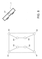
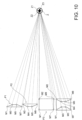
- the data processor DP is configured to perform step b) generate a set of patterns P1-P3, each pattern P1-P3 having M fiducial markers, where M is an integer superior or equal to 3 and strictly inferior to N tot ; the set of patterns P1-P3 including N fiducial markers M1-M8, where N is an integer inferior or equal to N tot .
- the set of patterns generated in step b), taken as a whole covers all or part of the N tot fiducial markers M1-M8 captured by the stereoscopic camera 2.
- Each pattern P1-P3 of the set generated in step b) is advantageously selected according to the positions of the corresponding M fiducial markers M1-M8 thereof with respect to each other.
- the relative positions of the M fiducial markers M1-M8 of a given pattern P1-P3 are compared therebetween in order to select the given pattern P1-P3.
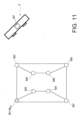
- the set of patterns P1-P3 generated in step b) advantageously satisfies a spread criterion that compares relative positions of the M fiducial markers M1-M8 for each pattern P1-P3 of the set, from the positions determined in step a); the spread criterion being designed to detect a minimal spatial spread between the M fiducial markers M1-M8 of a given pattern P1-P3 of the set.
- the relative positions of the M fiducial markers M1-M8 of a given pattern P1-P3 define a maximum distance between two fiducial markers.
- the given pattern P1-P3 of the set may be selected if the maximum distance exceeds a first predetermined threshold, corresponding to a first minimal spatial spread.
- a secondary distance can be defined between the line formed by said two fiducial markers (defining the maximum distance) and the other fiducial markers of the given pattern P1-P3 of the set.
- the given pattern P1-P3 may be selected if the secondary distance exceeds a second predetermined threshold, corresponding to a second minimal spatial spread.
- the given pattern P1-P3 of the set defines a centroid, and may be selected if the distance between its fiducial markers M1-M8 and the centroid exceeds a third predetermined threshold, corresponding to a third minimal spatial spread.
- the fiducial markers M1-M8 of a given pattern P1-P3 form vertices delimiting a surface.
- the given pattern P1-P3 may be selected if the surface exceeds an area threshold.
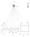
- Each pattern P1-P3 of the set generated in step b) is advantageously selected according to the positions of the corresponding M fiducial markers M1-M8 thereof with respect to the stereoscopic camera 2.
- the set of patterns P1-P3 generated in step b) advantageously satisfies a visibility criterion that compares visibility levels of the M fiducial markers M1-M8 between all patterns P1-P3 of the set, from the images 20 captured by stereoscopic camera 2; the visibility criterion being designed to detect a minimal visibility level at which the M fiducial markers M1-M8 of a given pattern P1-P3 of the set are discerned by the stereoscopic camera 2 within a predetermined margin of error.
- the minimal visibility level may result in a visibility angle, preferably of 50°.
- the set of patterns P1-P3 generated in step b) advantageously satisfies both the spread criterion and the visibility criterion.
- the data processor DP may be configured to perform step b) by:
- the data processor DP may be configured to perform step: b 3 ) select a set of patterns P1-P3, from patterns generated in step b 2 ), that satisfies the spread criterion.
- the data processor DP may be configured to perform step: b' 3 ) select a set of patterns P1-P3, from patterns generated in step b 2 ), that satisfies the visibility criterion.
- the data processor DP is advantageously configured to perform step: b" 3 ) select a set of patterns P1-P3, from patterns generated in step b 2 ), that satisfies both the spread criterion and the visibility criterion.
- the data processor DP is advantageously configured to perform step b) by setting the integer M of fiducial markers M1-M8 to the integer that is equal to N tot - 1.
- the data processor DP is configured to perform step c) for each pattern P1-P3 of the set generated in step b):
- the pose of the reference zone Z ref may be computed from the extracted positions of the corresponding M fiducial markers M1-M8 by using a matrix transformation between coordinate systems.
- the matrix transformation may be a rigid transformation referring to geometric transformation of a Euclidean space that preserves the Euclidean distance between every pair of points.
- the rigid transformation may include rotations, translations, reflections, or a combination thereof.
- the data processor DP may implement Kabsch-Umeyama algorithm in order to compute the pose of the reference zone Z ref from the extracted positions of the corresponding M fiducial markers M1-M8.
- the data processor DP may be configured to perform step c') extract the positions of the N fiducial markers M1-M8 from step a); and compute a pose of the reference zone Z ref , in the reference coordinate system, from the extracted positions of the N fiducial markers M1-M8.
- the pose of the reference zone Z ref may be computed from the extracted positions of the N fiducial markers M1-M8 by using a matrix transformation between coordinate systems.
- the matrix transformation may be a rigid transformation referring to geometric transformation of a Euclidean space that preserves the Euclidean distance between every pair of points.
- the rigid transformation may include rotations, translations, reflections, or a combination thereof.
- the data processor DP may implement Kabsch-Umeyama algorithm in order to compute the pose of the reference zone Z ref from the extracted positions of the N fiducial markers M1-M8.
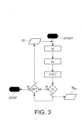
- the data processor DP is configured to perform step d) apply a criterion to compare the poses of the reference zone Z ref computed in step c) therebetween for the set of patterns P1-P3, the criterion being designed to detect a presence of at least one partially-obscured fiducial marker M po within the N fiducial markers M1-M8.
- Step d) is performed by the data processor DP as long as images 20 of N tot fiducial markers M1-M8 are captured by the stereoscopic camera 2.
- the criterion applied in step d) is advantageously a spread criterion.
- the spread criterion applied in step d) is advantageously designed to detect a minimal spatial spread between the poses of the reference zone Z ref computed in step c) for the set of patterns P1-P3, so as to detect the presence of the at least one partially-obscured fiducial marker M po within the N fiducial markers M1-M8.
- step d) may be carried out by comparing the positions Z1, Z2, Z3 of the reference zone Z ref computed in step c) therebetween for the set of patterns P1-P3.
- the positions Z1, Z2, Z3 of the reference zone Z ref computed in step c) for the set of patterns P1-P3 do not excess a spread threshold therebetween, indicating the absence of a partially-obscured fiducial marker M po .
- the positions Z1, Z2, Z3 of the reference zone Z ref computed in step c) for the set of patterns P1-P3 excess a spread threshold therebetween, indicating the presence of a partially-obscured fiducial marker M po .
- step c') when step c') is performed, the data processor DP is configured to perform step d) apply a criterion to compare the pose of the reference zone Z ref computed in step c'), with the poses of the reference zone Z ref computed in step c) for the set of patterns P1-P3, the criterion being designed to detect a presence of at least one partially-obscured fiducial marker M po within the N fiducial markers M1-M8.
- Step d) is performed by the data processor DP as long as images 20 of N tot fiducial markers M1-M8 are captured by the stereoscopic camera 2.
- the criterion applied in step d) is advantageously a spread criterion.
- step c') is performed by the data processor DP
- the spread criterion applied in step d) is advantageously designed to detect a minimal spatial spread between the pose of the reference zone Z ref computed in step c') and each pose of the reference zone Z ref computed in step c), so as to detect the presence of the at least one partially-obscured fiducial marker M po within the N fiducial markers M1-M8.
- step d) may be carried out by comparing the position Z of the reference zone Z ref computed in step c'), with the positions Z1, Z2, Z3 of the reference zone Z ref computed in step c) for the set of patterns P1-P3.
- the position Z of the reference zone Z ref computed in step c') and the positions Z1, Z2, Z3 of the reference zone Z ref computed in step c) do not excess a spread threshold, indicating the absence of a partially-obscured fiducial marker M po .
- the position Z of the reference zone Z ref computed in step c') and the positions Z1, Z2, Z3 of the reference zone Z ref computed in step c) excess a spread threshold, indicating the presence of a partially-obscured fiducial marker M po .
- the pose of the reference zone Z ref may be computed from the extracted positions of the m fiducial markers M1-M8 by using a matrix transformation between coordinate systems.
- the matrix transformation may be a rigid transformation referring to geometric transformation of a Euclidean space that preserves the Euclidean distance between every pair of points.
- the rigid transformation may include rotations, translations, reflections, or a combination thereof.
- the data processor DP may implement Kabsch-Umeyama algorithm in order to compute the pose of the reference zone Z ref from the extracted positions of the m fiducial markers M1-M8.
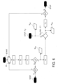
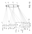
- the criterion applied in step e) to compare the computed poses of the reference zone Z ref therebetween for the set of sub-patterns SP1-SP4 is advantageously a spread criterion.
- the most distant position Z14 is obtained for the sub-pattern SP4 that does not contain the partially-obscured fiducial marker M po . Therefore, it is possible to locate the partially-obscured fiducial marker M po , which is the fiducial marker M1 of the corresponding pattern P1 that is not present in the sub-pattern SP4.
- Step e) is performed by the data processor DP as long as images 20 of N tot fiducial markers M1-M8 are captured by the stereoscopic camera 2.
- step e) is performed by the data processor DP
- the data processor DP is advantageously further configured to perform steps:
- Step f 1 is performed by the data processor DP as long as images 20 of N tot fiducial markers M1-M8 are captured by the stereoscopic camera 2.
Landscapes
- Health & Medical Sciences (AREA)
- Surgery (AREA)
- Engineering & Computer Science (AREA)
- Life Sciences & Earth Sciences (AREA)
- Medical Informatics (AREA)
- Robotics (AREA)
- Biomedical Technology (AREA)
- Heart & Thoracic Surgery (AREA)
- Nuclear Medicine, Radiotherapy & Molecular Imaging (AREA)
- Molecular Biology (AREA)
- Animal Behavior & Ethology (AREA)
- General Health & Medical Sciences (AREA)
- Public Health (AREA)
- Veterinary Medicine (AREA)
- Length Measuring Devices By Optical Means (AREA)
- Image Processing (AREA)
Priority Applications (5)
| Application Number | Priority Date | Filing Date | Title |
|---|---|---|---|
| EP23315014.3A EP4406503A1 (de) | 2023-01-27 | 2023-01-27 | Chirurgisches navigationssystem mit handhabung von teilweise verborgenen markern |
| PCT/EP2024/051809 WO2024156818A1 (en) | 2023-01-27 | 2024-01-25 | Surgical navigation system dealing with partially-obscured markers |
| CN202480009445.8A CN120693122A (zh) | 2023-01-27 | 2024-01-25 | 处理部分被遮挡标记的手术导航系统 |
| JP2025543317A JP2026502682A (ja) | 2023-01-27 | 2024-01-25 | 部分的に隠蔽されたマーカに対処する手術ナビゲーション・システム |
| AU2024211721A AU2024211721A1 (en) | 2023-01-27 | 2024-01-25 | Surgical navigation system dealing with partially-obscured markers |
Applications Claiming Priority (1)
| Application Number | Priority Date | Filing Date | Title |
|---|---|---|---|
| EP23315014.3A EP4406503A1 (de) | 2023-01-27 | 2023-01-27 | Chirurgisches navigationssystem mit handhabung von teilweise verborgenen markern |
Publications (1)
| Publication Number | Publication Date |
|---|---|
| EP4406503A1 true EP4406503A1 (de) | 2024-07-31 |
Family
ID=85251867
Family Applications (1)
| Application Number | Title | Priority Date | Filing Date |
|---|---|---|---|
| EP23315014.3A Pending EP4406503A1 (de) | 2023-01-27 | 2023-01-27 | Chirurgisches navigationssystem mit handhabung von teilweise verborgenen markern |
Country Status (5)
| Country | Link |
|---|---|
| EP (1) | EP4406503A1 (de) |
| JP (1) | JP2026502682A (de) |
| CN (1) | CN120693122A (de) |
| AU (1) | AU2024211721A1 (de) |
| WO (1) | WO2024156818A1 (de) |
Citations (4)
| Publication number | Priority date | Publication date | Assignee | Title |
|---|---|---|---|---|
| US5828770A (en) | 1996-02-20 | 1998-10-27 | Northern Digital Inc. | System for determining the spatial position and angular orientation of an object |
| US20160242858A1 (en) * | 2015-02-25 | 2016-08-25 | Mako Surgical Corp. | Navigation Systems And Methods For Reducing Tracking Interruptions During A Surgical Procedure |
| US20210401510A1 (en) * | 2012-06-21 | 2021-12-30 | Globus Medical, Inc. | Dynamic Reference Arrays and Methods of Use |
| US20220409288A1 (en) * | 2019-11-19 | 2022-12-29 | Quantum Surgical | Navigation method for positioning a medical robot |
-
2023
- 2023-01-27 EP EP23315014.3A patent/EP4406503A1/de active Pending
-
2024
- 2024-01-25 JP JP2025543317A patent/JP2026502682A/ja active Pending
- 2024-01-25 AU AU2024211721A patent/AU2024211721A1/en active Pending
- 2024-01-25 WO PCT/EP2024/051809 patent/WO2024156818A1/en not_active Ceased
- 2024-01-25 CN CN202480009445.8A patent/CN120693122A/zh active Pending
Patent Citations (4)
| Publication number | Priority date | Publication date | Assignee | Title |
|---|---|---|---|---|
| US5828770A (en) | 1996-02-20 | 1998-10-27 | Northern Digital Inc. | System for determining the spatial position and angular orientation of an object |
| US20210401510A1 (en) * | 2012-06-21 | 2021-12-30 | Globus Medical, Inc. | Dynamic Reference Arrays and Methods of Use |
| US20160242858A1 (en) * | 2015-02-25 | 2016-08-25 | Mako Surgical Corp. | Navigation Systems And Methods For Reducing Tracking Interruptions During A Surgical Procedure |
| US20220409288A1 (en) * | 2019-11-19 | 2022-12-29 | Quantum Surgical | Navigation method for positioning a medical robot |
Also Published As
| Publication number | Publication date |
|---|---|
| AU2024211721A1 (en) | 2025-07-17 |
| JP2026502682A (ja) | 2026-01-23 |
| WO2024156818A1 (en) | 2024-08-02 |
| CN120693122A (zh) | 2025-09-23 |
Similar Documents
| Publication | Publication Date | Title |
|---|---|---|
| EP3764932B1 (de) | Verfahren und systeme zur führung einer manuellen bewegung medizinischer systeme | |
| US20210186632A1 (en) | Surgical guidance system and method with indicator light | |
| US20230165649A1 (en) | A collaborative surgical robotic platform for autonomous task execution | |
| EP1871267B1 (de) | System zur haptischen führung | |
| EP4135614B1 (de) | System zur bestimmung eines sicherheitskriteriums während einer autonomen manipulation eines chirurgischen werkzeugs durch ein robotersystem zur behandlung einer anatomischen struktur | |
| JP2021194538A (ja) | 基準シードを介した可視光での外科手術での対象の追跡および合成画像登録 | |
| US20230263541A1 (en) | Robotic spine surgery system | |
| EP4406503A1 (de) | Chirurgisches navigationssystem mit handhabung von teilweise verborgenen markern | |
| US20230190391A1 (en) | Surgical robotic system | |
| EP4302718B1 (de) | Chirurgisches navigationssystem | |
| WO2023057472A1 (en) | Surgical robotic system and method for defining a prohibited volume for such a surgical robotic system | |
| US20240099781A1 (en) | Neuromapping systems, methods, and devices | |
| EP4497406A1 (de) | Chirurgisches robotersystem und verfahren zur definition eines eingeschränkten zugangsvolumens für solch ein chirurgisches robotersystem | |
| US20260124005A1 (en) | Surgical robotic system and method for defining a prohibited volume for such a surgical robotic system | |
| US20250134606A1 (en) | Robotic surgery system with user interfacing | |
| WO2026050207A1 (en) | System and method for aligning a robot end-effector with an axis |
Legal Events
| Date | Code | Title | Description |
|---|---|---|---|
| PUAI | Public reference made under article 153(3) epc to a published international application that has entered the european phase |
Free format text: ORIGINAL CODE: 0009012 |
|
| STAA | Information on the status of an ep patent application or granted ep patent |
Free format text: STATUS: THE APPLICATION HAS BEEN PUBLISHED |
|
| AK | Designated contracting states |
Kind code of ref document: A1 Designated state(s): AL AT BE BG CH CY CZ DE DK EE ES FI FR GB GR HR HU IE IS IT LI LT LU LV MC ME MK MT NL NO PL PT RO RS SE SI SK SM TR |
|
| STAA | Information on the status of an ep patent application or granted ep patent |
Free format text: STATUS: REQUEST FOR EXAMINATION WAS MADE |
|
| 17P | Request for examination filed |
Effective date: 20250102 |
|
| GRAP | Despatch of communication of intention to grant a patent |
Free format text: ORIGINAL CODE: EPIDOSNIGR1 |
|
| STAA | Information on the status of an ep patent application or granted ep patent |
Free format text: STATUS: GRANT OF PATENT IS INTENDED |
|
| INTG | Intention to grant announced |
Effective date: 20260227 |