EP4404666A1 - Elektronische vorrichtung zur verbesserung der abdeckung einer zelle und betriebsverfahren dafür - Google Patents
Elektronische vorrichtung zur verbesserung der abdeckung einer zelle und betriebsverfahren dafür Download PDFInfo
- Publication number
- EP4404666A1 EP4404666A1 EP22887393.1A EP22887393A EP4404666A1 EP 4404666 A1 EP4404666 A1 EP 4404666A1 EP 22887393 A EP22887393 A EP 22887393A EP 4404666 A1 EP4404666 A1 EP 4404666A1
- Authority
- EP
- European Patent Office
- Prior art keywords
- external device
- processor
- electronic device
- channel
- reference signal
- Prior art date
- Legal status (The legal status is an assumption and is not a legal conclusion. Google has not performed a legal analysis and makes no representation as to the accuracy of the status listed.)
- Pending
Links
Images


Classifications
-
- H—ELECTRICITY
- H04—ELECTRIC COMMUNICATION TECHNIQUE
- H04B—TRANSMISSION
- H04B1/00—Details of transmission systems, not covered by a single one of groups H04B3/00 - H04B13/00; Details of transmission systems not characterised by the medium used for transmission
- H04B1/69—Spread spectrum techniques
- H04B1/713—Spread spectrum techniques using frequency hopping
- H04B1/7136—Arrangements for generation of hop frequencies, e.g. using a bank of frequency sources, using continuous tuning or using a transform
-
- H—ELECTRICITY
- H04—ELECTRIC COMMUNICATION TECHNIQUE
- H04W—WIRELESS COMMUNICATION NETWORKS
- H04W72/00—Local resource management
- H04W72/20—Control channels or signalling for resource management
- H04W72/23—Control channels or signalling for resource management in the downlink direction of a wireless link, i.e. towards a terminal
-
- H—ELECTRICITY
- H04—ELECTRIC COMMUNICATION TECHNIQUE
- H04L—TRANSMISSION OF DIGITAL INFORMATION, e.g. TELEGRAPHIC COMMUNICATION
- H04L25/00—Baseband systems
- H04L25/02—Details ; arrangements for supplying electrical power along data transmission lines
- H04L25/0202—Channel estimation
- H04L25/0222—Estimation of channel variability, e.g. coherence bandwidth, coherence time, fading frequency
-
- H—ELECTRICITY
- H04—ELECTRIC COMMUNICATION TECHNIQUE
- H04B—TRANSMISSION
- H04B1/00—Details of transmission systems, not covered by a single one of groups H04B3/00 - H04B13/00; Details of transmission systems not characterised by the medium used for transmission
- H04B1/69—Spread spectrum techniques
- H04B1/713—Spread spectrum techniques using frequency hopping
- H04B1/7143—Arrangements for generation of hop patterns
-
- H—ELECTRICITY
- H04—ELECTRIC COMMUNICATION TECHNIQUE
- H04J—MULTIPLEX COMMUNICATION
- H04J11/00—Orthogonal multiplex systems, e.g. using WALSH codes
-
- H—ELECTRICITY
- H04—ELECTRIC COMMUNICATION TECHNIQUE
- H04L—TRANSMISSION OF DIGITAL INFORMATION, e.g. TELEGRAPHIC COMMUNICATION
- H04L25/00—Baseband systems
- H04L25/02—Details ; arrangements for supplying electrical power along data transmission lines
- H04L25/0202—Channel estimation
- H04L25/021—Estimation of channel covariance
-
- H—ELECTRICITY
- H04—ELECTRIC COMMUNICATION TECHNIQUE
- H04L—TRANSMISSION OF DIGITAL INFORMATION, e.g. TELEGRAPHIC COMMUNICATION
- H04L25/00—Baseband systems
- H04L25/02—Details ; arrangements for supplying electrical power along data transmission lines
- H04L25/0202—Channel estimation
- H04L25/0224—Channel estimation using sounding signals
- H04L25/0226—Channel estimation using sounding signals sounding signals per se
-
- H—ELECTRICITY
- H04—ELECTRIC COMMUNICATION TECHNIQUE
- H04L—TRANSMISSION OF DIGITAL INFORMATION, e.g. TELEGRAPHIC COMMUNICATION
- H04L25/00—Baseband systems
- H04L25/02—Details ; arrangements for supplying electrical power along data transmission lines
- H04L25/0202—Channel estimation
- H04L25/0224—Channel estimation using sounding signals
- H04L25/0228—Channel estimation using sounding signals with direct estimation from sounding signals
-
- H—ELECTRICITY
- H04—ELECTRIC COMMUNICATION TECHNIQUE
- H04W—WIRELESS COMMUNICATION NETWORKS
- H04W72/00—Local resource management
- H04W72/04—Wireless resource allocation
-
- H—ELECTRICITY
- H04—ELECTRIC COMMUNICATION TECHNIQUE
- H04W—WIRELESS COMMUNICATION NETWORKS
- H04W72/00—Local resource management
- H04W72/04—Wireless resource allocation
- H04W72/044—Wireless resource allocation based on the type of the allocated resource
- H04W72/0453—Resources in frequency domain, e.g. a carrier in FDMA
-
- H—ELECTRICITY
- H04—ELECTRIC COMMUNICATION TECHNIQUE
- H04W—WIRELESS COMMUNICATION NETWORKS
- H04W72/00—Local resource management
- H04W72/20—Control channels or signalling for resource management
- H04W72/21—Control channels or signalling for resource management in the uplink direction of a wireless link, i.e. towards the network
-
- H—ELECTRICITY
- H04—ELECTRIC COMMUNICATION TECHNIQUE
- H04W—WIRELESS COMMUNICATION NETWORKS
- H04W72/00—Local resource management
- H04W72/50—Allocation or scheduling criteria for wireless resources
- H04W72/54—Allocation or scheduling criteria for wireless resources based on quality criteria
-
- H—ELECTRICITY
- H04—ELECTRIC COMMUNICATION TECHNIQUE
- H04W—WIRELESS COMMUNICATION NETWORKS
- H04W72/00—Local resource management
- H04W72/50—Allocation or scheduling criteria for wireless resources
- H04W72/54—Allocation or scheduling criteria for wireless resources based on quality criteria
- H04W72/542—Allocation or scheduling criteria for wireless resources based on quality criteria using measured or perceived quality
-
- H—ELECTRICITY
- H04—ELECTRIC COMMUNICATION TECHNIQUE
- H04W—WIRELESS COMMUNICATION NETWORKS
- H04W88/00—Devices specially adapted for wireless communication networks, e.g. terminals, base stations or access point devices
- H04W88/08—Access point devices
Definitions
- Various embodiments of the disclosure relate to a device and a method for cell coverage enhancement by an electronic device in a wireless communication system.
- a communication system e.g., 5th generation (5G), pre-5G, or new radio (NR)
- 5G 5th generation
- NR new radio
- An electronic device e.g., a base station of a wireless communication system may apply a technology to extend the coverage of a cell operated by the electronic device.
- an electronic device e.g., a base station
- an inter-slot channel estimation technology for improving the channel estimation performance of an external device (e.g., a terminal) located in a cell edge region.
- the inter-slot channel estimation technology may include a method of assigning reference signals (e.g., a demodulation reference signal (DMRS)) via multiple consecutive slots of the same frequency band.
- DMRS demodulation reference signal
- An external device may improve channel estimation performance by estimating a channel by using reference signals received via multiple consecutive slots.
- the channel estimation performance of the external device may be deteriorated due to occurrence of a relatively severe difference in channel gain between different time resources (e.g., slots).
- Various embodiments of the disclosure provide a device and a method for cell coverage enhancement by an electronic device (e.g., a base station) in a wireless communication system.
- an electronic device e.g., a base station
- an electronic device may include a communication circuit and a processor operatively connected to the communication circuit, wherein the processor identifies a channel variation of an external device configured to perform communication via the communication circuit, configures a frequency hopping interval corresponding to the external device, based on the channel variation of the external device, transmits information related to the frequency hopping interval to the external device, and transmits, based on the frequency hopping interval, at least one reference signal assigned to at least one slot corresponding to at least one frequency band to the external device.
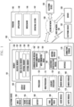
- the processor 120 may execute, for example, software (e.g., a program 140) to control at least one other component (e.g., a hardware or software component) of the electronic device 101 coupled with the processor 120, and may perform various data processing or computation. According to one embodiment, as at least part of the data processing or computation, the processor 120 may store a command or data received from another component (e.g., the sensor module 176 or the communication module 190) in volatile memory 132, process the command or the data stored in the volatile memory 132, and store resulting data in non-volatile memory 134.
- software e.g., a program 140
- the processor 120 may store a command or data received from another component (e.g., the sensor module 176 or the communication module 190) in volatile memory 132, process the command or the data stored in the volatile memory 132, and store resulting data in non-volatile memory 134.
- the artificial neural network may be a deep neural network (DNN), a convolutional neural network (CNN), a recurrent neural network (RNN), a restricted boltzmann machine (RBM), a deep belief network (DBN), a bidirectional recurrent deep neural network (BRDNN), deep Q-network or a combination of two or more thereof but is not limited thereto.
- the artificial intelligence model may, additionally or alternatively, include a software structure other than the hardware structure.
- the program 140 may be stored in the memory 130 as software, and may include, for example, an operating system (OS) 142, middleware 144, or an application 146.
- OS operating system
- middleware middleware
- application application
- the sound output module 155 may output sound signals to the outside of the electronic device 101.
- the sound output module 155 may include, for example, a speaker or a receiver.
- the speaker may be used for general purposes, such as playing multimedia or playing record.
- the receiver may be used for receiving incoming calls. According to an embodiment, the receiver may be implemented as separate from, or as part of the speaker.
- the display module 160 may visually provide information to the outside (e.g., a user) of the electronic device 101.
- the display module 160 may include, for example, a display, a hologram device, or a projector and control circuitry to control a corresponding one of the display, hologram device, and projector.
- the display module 160 may include a touch sensor adapted to detect a touch, or a pressure sensor adapted to measure the intensity of force incurred by the touch.
- the audio module 170 may convert a sound into an electrical signal and vice versa. According to an embodiment, the audio module 170 may obtain the sound via the input module 150, or output the sound via the sound output module 155 or a headphone of an external electronic device (e.g., the external electronic device 102) directly (e.g., wiredly) or wirelessly coupled with the electronic device 101.
- an external electronic device e.g., the external electronic device 102
- directly e.g., wiredly
- wirelessly e.g., wirelessly
- the sensor module 176 may detect an operational state (e.g., power or temperature) of the electronic device 101 or an environmental state (e.g., a state of a user) external to the electronic device 101, and then generate an electrical signal or data value corresponding to the detected state.
- the sensor module 176 may include, for example, a gesture sensor, a gyro sensor, an atmospheric pressure sensor, a magnetic sensor, an acceleration sensor, a grip sensor, a proximity sensor, a color sensor, an infrared (IR) sensor, a biometric sensor, a temperature sensor, a humidity sensor, or an illuminance sensor.
- the interface 177 may support one or more specified protocols to be used for the electronic device 101 to be coupled with the external electronic device (e.g., the external electronic device 102) directly (e.g., wiredly) or wirelessly.
- the interface 177 may include, for example, a high definition multimedia interface (HDMI), a universal serial bus (USB) interface, a secure digital (SD) card interface, or an audio interface.
- HDMI high definition multimedia interface
- USB universal serial bus
- SD secure digital
- the haptic module 179 may convert an electrical signal into a mechanical stimulus (e.g., a vibration or a movement) or electrical stimulus which may be recognized by a user via his tactile sensation or kinesthetic sensation.
- the haptic module 179 may include, for example, a motor, a piezoelectric element, or an electric stimulator.
- the camera module 180 may capture a still image or moving images.
- the camera module 180 may include one or more lenses, image sensors, image signal processors, or flashes.
- the power management module 188 may manage power supplied to the electronic device 101.
- the power management module 188 may be implemented as at least part of, for example, a power management integrated circuit (PMIC).
- PMIC power management integrated circuit
- the battery 189 may supply power to at least one component of the electronic device 101.
- the battery 189 may include, for example, a primary cell which is not rechargeable, a secondary cell which is rechargeable, or a fuel cell.
- the communication module 190 may include a wireless communication module 192 (e.g., a cellular communication module, a short-range wireless communication module, or a global navigation satellite system (GNSS) communication module) or a wired communication module 194 (e.g., a local area network (LAN) communication module or a power line communication (PLC) module).
- a wireless communication module 192 e.g., a cellular communication module, a short-range wireless communication module, or a global navigation satellite system (GNSS) communication module
- GNSS global navigation satellite system
- wired communication module 194 e.g., a local area network (LAN) communication module or a power line communication (PLC) module.
- LAN local area network
- PLC power line communication
- a corresponding one of these communication modules may communicate with the external electronic device via the first network 198 (e.g., a short-range communication network, such as Bluetooth TM , wireless-fidelity (Wi-Fi) direct, or infrared data association (IrDA)) or the second network 199 (e.g., a long-range communication network, such as a legacy cellular network, a 5G network, a next-generation communication network, the Internet, or a computer network (e.g., LAN or wide area network (WAN)).
- first network 198 e.g., a short-range communication network, such as Bluetooth TM , wireless-fidelity (Wi-Fi) direct, or infrared data association (IrDA)
- the second network 199 e.g., a long-range communication network, such as a legacy cellular network, a 5G network, a next-generation communication network, the Internet, or a computer network (e.g., LAN or wide area network (WAN)).
- the wireless communication module 192 may identify and authenticate the electronic device 101 in a communication network, such as the first network 198 or the second network 199, using subscriber information (e.g., international mobile subscriber identity (IMSI)) stored in the subscriber identification module 196.
- subscriber information e.g., international mobile subscriber identity (IMSI)
- the wireless communication module 192 may support a 5G network, after a 4G network, and next-generation communication technology, e.g., new radio (NR) access technology.
- the NR access technology may support enhanced mobile broadband (eMBB), massive machine type communications (mMTC), or ultra-reliable and low-latency communications (URLLC).
- eMBB enhanced mobile broadband
- mMTC massive machine type communications
- URLLC ultra-reliable and low-latency communications
- the wireless communication module 192 may support a high-frequency band (e.g., the mmWave band) to achieve, e.g., a high data transmission rate.
- the wireless communication module 192 may support various technologies for securing performance on a high-frequency band, such as, e.g., beamforming, massive multiple-input and multiple-output (massive MIMO), full dimensional MIMO (FD-MIMO), array antenna, analog beam-forming, or large scale antenna.
- the wireless communication module 192 may support various requirements specified in the electronic device 101, an external electronic device (e.g., the external electronic device 104), or a network system (e.g., the second network 199).
- the wireless communication module 192 may support a peak data rate (e.g., 20Gbps or more) for implementing eMBB, loss coverage (e.g., 164dB or less) for implementing mMTC, or U-plane latency (e.g., 0.5ms or less for each of downlink (DL) and uplink (UL), or a round trip of 1ms or less) for implementing URLLC.
- the subscriber identification module 196 may include a plurality of subscriber identification modules. For example, the plurality of subscriber identification modules may store different subscriber information.
- the antenna module 197 may transmit or receive a signal or power to or from the outside (e.g., the external electronic device) of the electronic device 101.
- the antenna module 197 may include an antenna including a radiating element composed of a conductive material or a conductive pattern formed in or on a substrate (e.g., a printed circuit board (PCB)).
- the antenna module 197 may include a plurality of antennas (e.g., array antennas). In such a case, at least one antenna appropriate for a communication scheme used in the communication network, such as the first network 198 or the second network 199, may be selected, for example, by the communication module 190 (e.g., the wireless communication module 192) from the plurality of antennas.
- the signal or the power may then be transmitted or received between the communication module 190 and the external electronic device via the selected at least one antenna.
- another component e.g., a radio frequency integrated circuit (RFIC)
- RFIC radio frequency integrated circuit
- the antenna module 197 may form an mmWave antenna module.
- the mmWave antenna module may include a printed circuit board, a RFIC disposed on a first surface (e.g., the bottom surface) of the printed circuit board, or adjacent to the first surface and capable of supporting a designated high-frequency band (e.g., the mmWave band), and a plurality of antennas (e.g., array antennas) disposed on a second surface (e.g., the top or a side surface) of the printed circuit board, or adjacent to the second surface and capable of transmitting or receiving signals of the designated high-frequency band.
- the plurality of antennas may include a patch array antenna and/or a dipole array antenna.
- At least some of the above-described components may be coupled mutually and communicate signals (e.g., commands or data) therebetween via an inter-peripheral communication scheme (e.g., a bus, general purpose input and output (GPIO), serial peripheral interface (SPI), or mobile industry processor interface (MIPI)).
- an inter-peripheral communication scheme e.g., a bus, general purpose input and output (GPIO), serial peripheral interface (SPI), or mobile industry processor interface (MIPI)
- the one or more external electronic devices receiving the request may perform the at least part of the function or the service requested, or an additional function or an additional service related to the request, and transfer an outcome of the performing to the electronic device 101.
- the electronic device 101 may provide the outcome, with or without further processing of the outcome, as at least part of a reply to the request.
- a cloud computing, distributed computing, mobile edge computing (MEC), or client-server computing technology may be used, for example.
- the electronic device 101 may provide ultra low-latency services using, e.g., distributed computing or mobile edge computing.
- the external electronic device 104 may include an internet-of-things (IoT) device.
- the server 108 may be an intelligent server using machine learning and/or a neural network.
- the external electronic device 104 or the server 108 may be included in the second network 199.
- the electronic device 101 may be applied to intelligent services (e.g., smart home, smart city, smart car, or healthcare) based on 5G communication technology or IoT-related technology.
- the electronic device may be one of various types of electronic devices.
- the electronic devices may include, for example, a portable communication device (e.g., a smartphone), a computer device, a portable multimedia device, a portable medical device, a camera, a wearable device, or a home appliance. According to an embodiment of the disclosure, the electronic devices are not limited to those described above.
- an element e.g., a first element
- the element may be coupled with the other element directly (e.g., wiredly), wirelessly, or via a third element.
- Various embodiments as set forth herein may be implemented as software (e.g., the program 140) including one or more instructions that are stored in a storage medium (e.g., internal memory 136 or external memory 138) that is readable by a machine (e.g., the electronic device 101).
- a processor e.g., the processor 120
- the machine e.g., the electronic device 101
- the one or more instructions may include a code generated by a complier or a code executable by an interpreter.
- a method may be included and provided in a computer program product.
- the computer program product may be traded as a product between a seller and a buyer.
- the computer program product may be distributed in the form of a machine-readable storage medium (e.g., compact disc read only memory (CD-ROM)), or be distributed (e.g., downloaded or uploaded) online via an application store (e.g., PlayStore TM ), or between two user devices (e.g., smart phones) directly. If distributed online, at least part of the computer program product may be temporarily generated or at least temporarily stored in the machine-readable storage medium, such as memory of the manufacturer's server, a server of the application store, or a relay server.
- CD-ROM compact disc read only memory
- an application store e.g., PlayStore TM
- two user devices e.g., smart phones
- each component e.g., a module or a program of the above-described components may include a single entity or multiple entities, and some of the multiple entities may be separately disposed in different components. According to various embodiments, one or more of the above-described components may be omitted, or one or more other components may be added. Alternatively or additionally, a plurality of components (e.g., modules or programs) may be integrated into a single component. In such a case, according to various embodiments, the integrated component may still perform one or more functions of each of the plurality of components in the same or similar manner as they are performed by a corresponding one of the plurality of components before the integration.
- operations performed by the module, the program, or another component may be carried out sequentially, in parallel, repeatedly, or heuristically, or one or more of the operations may be executed in a different order or omitted, or one or more other operations may be added.
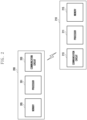
- FIG. 2 is a block diagram of a wireless communication system for channel estimation according to various embodiments.
- an electronic device 200 may be at least partially similar to the electronic device 101 of FIG. 1 or may include another embodiment of the electronic device.
- the external device 210 may be at least partially similar to the electronic device 101 of FIG. 1 or may include another embodiment of an external device.
- the wireless communication system may include an electronic device 200 and at least one external device 210.
- the electronic device 200 may communicate with the external device 210 by using a radio resource.
- the electronic device 200 may include a transmission node or a base station which allocates a radio resource (e.g., a frequency resource and/or a time resource) to the external device 210.
- the electronic device 200 may include an evolved node B (eNB) and/or a next generation node B (gNB).
- the external device 210 may include a user terminal (user equipment (UE)) which performs communication with the electronic device 200 by using a radio resource allocated from the electronic device 200.
- UE user equipment
- the electronic device 200 may include a processor 201, a communication circuit 203, and/or a memory 205.
- the processor 201 may be substantially the same as the processor 120 of FIG. 1 or may include the processor 120.
- the communication circuit 203 may be substantially the same as the wireless communication module 192 of FIG. 1 or may include the wireless communication module 192.
- the memory 205 may be substantially the same as the memory 130 of FIG. 1 or may include the memory 130.
- the processor 201 may be operatively connected to the communication circuit 203 and/or the memory 205.
- the processor 201 may identify a channel variation of the external device 210 to which communication is connected. According to an embodiment, the processor 201 may determine whether the external device 210, in which a communication link has been established with the electronic device 200, is located in a cell edge region. For example, when information related to a channel state provided from the external device 210 satisfies a designated first condition, the processor 201 may determine that the external device 210 is located in the cell edge region. For example, when the processor 201 determines that the external device 210 is located in the cell edge region, the processor 201 may identify a channel variation of the external device 210.
- the processor 201 may control the communication circuit 203 to transmit a request signal related to the channel variation to the external device 210.
- the processor 201 may obtain information related to the channel variation from the external device 210 via the communication circuit 203 in response to the request signal.
- the state satisfying the designated first condition may include a state in which a channel state of the external device 210 is equal to or smaller than a reference state continuously for a designated first time period.
- the processor 201 may estimate a Doppler spread value, based on an uplink reference signal received from the external device 210 via the communication circuit 203.
- the processor 201 may estimate the channel variation of the external device 210, based on the Doppler spread value estimated based on the uplink reference signal.
- the uplink reference signal may include a sounding reference signal (SRS), a phase tracking reference signal (PTRS), and/or a demodulation reference signal (DMRS).
- SRS sounding reference signal
- PTRS phase tracking reference signal
- DMRS demodulation reference signal
- the processor 201 may configure a frequency hopping interval of the external device 210, based on the channel variation of the external device 210. According to an embodiment, the processor 201 may configure, as the frequency hopping interval of the external device 210, a frequency hopping interval corresponding to the channel variation of the external device 210, which is detected in a predefined frequency hopping interval table.
- the frequency hopping interval may include the number of slots consecutively assigned to the external device 210 in the same frequency band.
- the frequency hopping interval table may include information related to the range of the channel variation of the external device 210, which corresponds to a specific frequency hopping interval.
- the processor 201 may configure, to a second interval (e.g., three slots), the frequency hopping interval of the external device 210 if the channel variation of the external device 210 is equal to or greater than the first reference variation (e.g., about 25 Hz) and is less than a second reference variation (e.g., about 50 Hz) (e.g., a second channel change level).
- the second reference variation may include a value larger than the first reference variation among multiple reference variations for configuration of a frequency hopping interval.
- the second channel change level may include a state in which the channel change of the external device 210 is greater than the first channel change level but is smaller than a third channel change level.
- the processor 201 may configure, to a third interval (e.g., two slots), the frequency hopping interval of the external device 210 if the channel variation of the external device 210 is equal to or greater than the second reference variation (e.g., about 50 Hz) and is less than a third reference variation (e.g., about 100 Hz) (e.g., the third channel change level).
- the third reference variation is a value larger than the second reference variation among multiple reference variations for configuration of a frequency hopping interval, and may include a maximum reference variation.
- the third channel change level may include a state in which the channel change of the external device 210 is greater than the second channel change level but is smaller than a fourth channel change level.
- the processor 201 may assign a second number (e.g., four) of reference signals per slot. For example, if the channel state (e.g., SNR) with respect to the external device 210 is greater than a reference state (e.g., a strong electric field) in a state where the channel variation of the external device 210 is less than the first reference variation, the processor 201 may assign the first number (e.g., one) of reference signals per slot.
- a reference state e.g., a strong electric field
- the processor 201 may control the communication circuit 203 to transmit, to the external device 210, information related to the assignment ratio of the reference signal and the frequency hopping interval associated with the external device 210.
- the information related to the assignment ratio of the reference signal and the frequency hopping interval associated with the external device 210 may be included in a system information block (SIB), a radio resource control (RRC) message (e.g., RRC connection reconfiguration), and/or a downlink control indicator (DCI) to as to be transmitted.
- SIB system information block
- RRC radio resource control
- DCI downlink control indicator
- the communication circuit 203 may support transmission and/or reception of signals and/or data between the electronic device 200 and the external device 210 via a wireless network.
- the communication circuit 203 may include a radio frequency integrated circuit (RFIC) and a radio frequency front end (RFFE) for communication with the external device 210.
- the wireless network may include a 2G network, a 3G network, a 4G network (e.g., long term evolution (LTE)), and/or a 5G network (e.g., new radio (NR)).
- LTE long term evolution
- NR new radio
- the external device 210 may include a processor 211, a communication circuit 213, and/or a memory 215.
- the processor 211 may be substantially the same as the processor 120 of FIG. 1 or may include the processor 120.
- the communication circuit 213 may be substantially the same as the wireless communication module 192 of FIG. 1 or may include the wireless communication module 192.
- the memory 215 may be substantially the same as the memory 130 of FIG. 1 or may include the memory 130.
- the processor 211 may be operatively connected to the communication circuit 213 and/or the memory 215.
- the processor 211 may identify a position change (or a moving distance) of the external device 210, which is measured based on a positioning system (GNSS) for a designated second time period.
- the processor 211 may control the communication circuit 213 to transmit information related to the position change (or the moving distance) of the external device 210 to the electronic device 200.
- GNSS positioning system
- the processor 211 may estimate a Doppler spread value of the external device 210.
- the processor 211 may control the communication circuit 213 to transmit information related to Doppler spread of the external device 210 to the electronic device 200.
- the processor 211 may measure the Doppler spread value of the external device 210 via a reference signal assigned to an n-th symbol and a reference signal allocated to an (n+k)th symbol.
- n and k are indices for distinguishing symbols and may include natural numbers.
- the processor 211 may configure the channel change level of the external device 210 to the second channel change level.
- the second channel change level may include a state in which the channel change of the external device 210 is greater than the first channel change level and is smaller than the third channel change level.
- the processor 211 may configure the channel change level of the external device 210 to the third channel change level.
- the third channel change level may include a state in which the channel change of the external device 210 is greater than the second channel change level and is smaller than the fourth channel change level.
- the processor 201 may configure the channel change level of the external device 210 to the fourth channel change level.
- the fourth channel change level may include a state in which the channel change of the external device 210 is relatively large.
- information related to multiple reference variations for determination of a channel change level may be obtained via an RRC message, a system information block (SIB), DCI, and/or a medium access control (MAC) control element (CE).
- SIB system information block
- DCI DCI
- CE medium access control control
- the processor 211 may control the communication circuit 213 to communicate with the electronic device 200, based on a channel estimation result. According to an embodiment, the processor 211 may restore, based on the channel estimation result, data received from the electronic device 200 via the communication circuit 213.
- the communication circuit 213 may support transmission and/or reception of signals and/or data between the external device 210 and the electronic device 200 via the wireless network.
- the communication circuit 213 may include an RFIC and an RFFE for communication with the electronic device 200.
- the communication circuit 213 may transmit information related to the channel variation of the external device 210 to the electronic device 200.
- information related to the channel variation of the external device 210 may be transmitted to the electronic device 200 via a physical uplink control channel (PUCCH) and/or an uplink control indicator (UCI).
- PUCCH physical uplink control channel
- UCI uplink control indicator
- the memory 215 may store various data used by at least one element (e.g., the processor 211 and/or the communication circuit 213) of the external device 210.
- the data may include information related to multiple reference variations for determination of a channel change level.
- the memory 215 may store various instructions executable by the processor 211.
- the processor identifies a channel variation of an external device configured to perform communication via the communication circuit, configures a frequency hopping interval corresponding to the external device, based on the channel variation of the external device, transmits information related to the frequency hopping interval to the external device, and transmits, based on the frequency hopping interval, at least one reference signal assigned to at least one slot corresponding to at least one frequency band to the external device.
- the processor may estimate the channel variation of the external device, based on information related to a position change of the external device, which is received from the external device via the communication circuit.
- the processor may estimate the channel variation of the external device, based on a Doppler spread value of the external device, which is received from the external device via the communication circuit.
- the processor may identify a Doppler spread value, based on an uplink reference signal received from the external device via the communication circuit, and may estimate the channel variation of the external device, based on the Doppler spread value.
- the processor may determine that the designated condition is satisfied.
- the processor 201 may estimate the channel variation of the external device 210, based on information related to Doppler spread of the external device 210, which is received from the external device 210 via the communication circuit 203.
- the information related to Doppler spread of the external device 210 may be received via a PUCCH and/or UCI.
- the processor 201 may estimate the channel variation of the external device 210, based on a TA value periodically received from the external device 210 via the communication circuit 203.
- the processor 201 may estimate a Doppler spread value, based on an uplink reference signal received from the external device 210 via the communication circuit 203.
- the processor 201 may estimate the channel variation of the external device 210, based on the Doppler spread value estimated based on the uplink reference signal.
- the channel variation of the external device 210 may indicate a difference (or difference value) of a channel change of the external device, which occurs during a designated time interval.
- the electronic device may configure a frequency hopping interval of the external device 210, based on the channel variation of the external device 210.
- the processor 201 may compare the channel variation of the external device 210 with multiple reference variations so as to configure the frequency hopping interval of the external device 210.
- the frequency hopping interval may include the number of slots consecutively assigned to the external device 210 in the same frequency band.
- the processor 201 may determine that the channel variation of the external device 210 is the first channel change level.
- the processor 201 may configure, as shown in FIG. 4B , the frequency hopping interval of the external device 210 to the first interval (e.g., four slots), based on the first channel change level.
- the first channel change level may include a state in which a channel change of the external device 210 is relatively small.
- the processor 201 may determine that the channel variation of the external device 210 is the second channel change level.
- the processor 201 may configure the frequency hopping interval of the external device 210 to the second interval (e.g., three slots), based on the second channel change level.
- the second channel change level may include a state in which the channel change of the external device 210 is greater than the first channel change level but is smaller than the third channel change level.
- the processor 201 may determine that the channel variation of the external device 210 is the third channel change level.
- the processor 201 may configure, as shown in FIG. 4A , the frequency hopping interval of the external device 210 to the third interval (e.g., two slots), based on the third channel change level.
- the third channel change level may include a state in which the channel change of the external device 210 is greater than the second channel change level but is smaller than the fourth channel change level.
- the processor 201 may determine that the channel variation of the external device 210 is the fourth channel change level.
- the processor 201 may configure the frequency hopping interval of the external device 210 to the fourth interval (e.g., one slot), based on the fourth channel change level.
- the fourth channel change level may include a state in which the channel change of the external device 210 is relatively large.
- the electronic device may transmit, to the external device 210, information related to the frequency hopping interval of the external device 210.
- the processor 201 may control the communication circuit 203 to transmit, to the external device 210, information related to an assignment ratio of a reference signal and/or the frequency hopping interval associated with the external device 210 via a system information block (SIB), an RRC message (e.g., RRC connection reconfiguration), and/or DCI.
- SIB system information block
- RRC message e.g., RRC connection reconfiguration
- DCI DCI
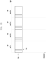
- the processor 201 may control the communication circuit 203 to transmit a reference signal 430 via a first frequency band 410 in an nth slot 400 and an (n+1)th slot 402 as shown in FIG. 4A .
- the processor 201 may control the communication circuit 203 to transmit the reference signal 430 via a second frequency band 420 differing from the first frequency band 410 in an (n+2)th slot 404 and an(n+3)th slot 406 as shown in FIG. 4A .
- the first frequency band 410 and the second frequency band 420 may be selected based on a predefined frequency hopping pattern.
- the processor 201 may control the communication circuit 203 to transmit the reference signal 430 via a third frequency band 450 in the nth slot 400, the (n+1)th slot 402, the (n+2)the slot 404, and the (n+3)th slot 406 as shown in FIG. 4B .
- the third frequency band 450 may include a frequency band that is the same as or is different from the first frequency band 410 or the second frequency band 420.
- the electronic device 200 may compare the channel variation of the external device 210 with three reference variations so as to configure the frequency hopping interval of the external device 210.
- the number of reference variations for configuration of the frequency hopping interval of the external device 210 is not limited thereto.
- the electronic device 200 may include at least one reference variation for configuration of the frequency hopping interval of the external device 210.
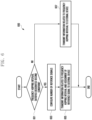
- FIG. 5 is a flowchart 500 for identifying a channel variation of an external device located in a cell edge region by an electronic device according to various embodiments.
- operations of FIG. 5 may be detailed operations of operation 301 of FIG. 3 .
- each of operations may be sequentially performed, but is not necessarily performed sequentially.
- the order of each operation may be changed, and at least two operations may be performed in parallel.
- an electronic device of FIG. 5 may be the electronic device 101 of FIG. 1 or the electronic device 200 of FIG. 2 .
- the electronic device may identify a channel state of the external device 210 connected to the electronic device 200 for communication.
- the processor 201 may receive information related to the channel state from the external device 210 via the communication circuit 203.
- the information related to the channel state may be received in response to a request signal related to the channel state, which has been transmitted to the external device 210 via the communication circuit 203.
- the information related to the channel state may be periodically received from the external device 210 via the communication circuit 203.
- the processor 201 may estimate the channel state of the external device 210, based on a reference signal received from the external device 210 via the communication circuit 203.
- the channel state of the external device 210 may include a modulation and coding scheme (MCS) level, a received signal strength indicator (RSSI), a reference signal received power (RSRP), a reference signal received quality (RSRQ), a signal to noise ratio (SNR), and/or a signal to interference and noise ratio (SINR).
- MCS modulation and coding scheme
- RSSI received signal strength indicator
- RSRP reference signal received power
- RSRQ reference signal received quality
- SNR signal to noise ratio
- SINR signal to interference and noise ratio
- the electronic device may identify whether the channel state of the external device 210 satisfies a specified first condition. According to an embodiment, if the channel state (e.g., an MCS level) of the external device 210 is continuously lower than a reference state for a designated first time period, the processor 201 may determine that the designated first condition is satisfied. According to an embodiment, if the channel state (e.g., an MCS level) of the external device 210 is continuously exceeds the reference state, the processor 201 may determine that the designated first condition is not satisfied.
- the channel state e.g., an MCS level
- the electronic device may determine that the external device 210 is not located in a cell edge region. Based on determination that the external device 210 is not located in the cell edge region, the electronic device (e.g., the processor 120 or 201) may terminate an embodiment for identifying the channel variation of the external device 210 located in the cell edge region.
- the designated first condition e.g., "No" in operation 503
- the electronic device may identify the channel variation of the external device 210 in operation 505. For example, if it is determined that the channel state of the external device 210 satisfies the designated first condition, the processor 201 may determine that the external device 210 is located in the cell edge region. The processor 201 may identify the channel variation of the external device 210 in order to configure a channel estimation scheme of the external device 210 located in a cell edge region.
- the designated first condition e.g., "Yes" in operation 503
- the electronic device may identify the channel variation of the external device 210 in operation 505. For example, if it is determined that the channel state of the external device 210 satisfies the designated first condition, the processor 201 may determine that the external device 210 is located in the cell edge region. The processor 201 may identify the channel variation of the external device 210 in order to configure a channel estimation scheme of the external device 210 located in a cell edge region.
- configuration of the channel estimation scheme of the external device 210 may include a series of operations of configuring a frequency hopping interval and/or an assignment ratio of a reference signal which are associated with assignment of at least one reference signal used for channel estimation of the external device 210.
- the frequency hopping interval may include the number of slots consecutively assigned to the external device 210 in the same frequency band.
- the assignment ratio of the reference signal may include the number of reference signals assigned in a time resource block (e.g., a slot).
- FIG. 6 is a flowchart for configuring an assignment ratio of a reference signal by an electronic device according to various embodiments.
- operations of FIG. 6 may be detailed operations of operation 305 of FIG. 3 .
- each of operations may be sequentially performed, but is not necessarily performed sequentially.
- the order of each operation may be changed, and at least two operations may be performed in parallel.
- an electronic device of FIG. 6 may be the electronic device 101 of FIG. 1 or the electronic device 200 of FIG. 2 .
- at least a part of FIG. 6 may be described with reference to FIG. 7A and FIG. 7B .
- FIG. 7A is an example of assigning a reference signal at a first ratio by an electronic device according to various embodiments.
- FIG. 7B is an example of assigning a reference signal at a second ratio by the electronic device according to various embodiments.
- the electronic device may configure, in operation 603, an assignment ratio of a reference signal corresponding to the external device 210.
- the processor 201 may configure the assignment ratio of the reference signal to be assigned to the external device 210, based on a channel state (e.g., SNR) and the channel variation of the external device 210.
- the assignment ratio of the reference signal may be configured to be proportional to the channel variation of the external device 210, and to be inversely proportional to the channel state (e.g., SNR).
- the processor 201 may assign the first number (e.g., one) of reference signals 770 per slot, as shown in FIG. 7B .
- the processor 201 may control the communication circuit 203 to transmit the first number of reference signals 770 via each of the nth slot 700, the (n+1)th slot 702, the (n+2)th slot 704, and the (n+3)th slot 706 assigned to a fifth frequency band 760, as shown in FIG. 7B .
- the electronic device may transmit, to the external device 210, information related to reference signal assignment information and the frequency hopping interval of the external device 210.
- the electronic device e.g., the processor 120 or 201 may transmit, to the external device 210, information related to the frequency hopping interval of the external device 210 in operation 607.
- the external device may identify a channel variation of the external device 210 in operation 801.
- the processor 211 may identify information related to the channel variation of the external device 210.
- a communication link is established with the electronic device 200 via the communication circuit 213, the processor 211 may periodically identify information related to the channel variation of the external device 210.
- the external device may estimate a channel with respect to the electronic device 200, based on information related to the assignment ratio of the reference signal and/or the frequency hopping interval received from the electronic device 200.
- the processor 211 may estimate a channel corresponding to the first frequency band 410 by using the reference signal 430 assigned to the nth slot 400 and (n+1)th slot 402 received via the first frequency band 410.
- the processor 211 may estimate the downlink channel with respect to the electronic device 200 by using the reference signal 430 assigned to the nth slot 400, the (n+1)th slot 402, the (n+2)th slot 404, and the (n+3)th slot 406 received via the third frequency band 450.
- the processor 211 may control the communication circuit 213 to transmit information related to the first channel change level to the electronic device 200.
- the first channel change level may include a state in which the channel change of the external device 210 is relatively small.
- an operation method of an electronic device may include identifying a channel variation of an external device connected to the electronic device for communication, configuring a frequency hopping interval corresponding to the external device, based on the channel variation of the external device, transmitting information related to the frequency hopping interval to the external device, and transmitting, based on the frequency hopping interval, at least one reference signal assigned to at least one slot corresponding to at least one frequency band to the external device.
- the identifying of the channel variation may include estimating the channel variation of the external device, based on a Doppler spread value of the external device, which is received from the external device.
- the identifying of the channel variation may include estimating the channel variation of the external device, based on a timing advance (TA) value of the external device, which is collected for a designated time period.
- TA timing advance
- the identifying of the channel variation may include identifying a Doppler spread value, based on an uplink reference signal received from the external device, and estimating the channel variation of the external device, based on the Doppler spread value.
- the configuring of the assignment ratio of the reference signal may include configuring, when the frequency hopping interval corresponding to the external device satisfies a designated condition, the assignment ratio of the reference signal corresponding to the external device, based on the channel variation of the external device and/or the channel state of the external device.
Landscapes
- Engineering & Computer Science (AREA)
- Computer Networks & Wireless Communication (AREA)
- Signal Processing (AREA)
- Power Engineering (AREA)
- Quality & Reliability (AREA)
- Mobile Radio Communication Systems (AREA)
Applications Claiming Priority (2)
| Application Number | Priority Date | Filing Date | Title |
|---|---|---|---|
| KR1020210142623A KR20230058874A (ko) | 2021-10-25 | 2021-10-25 | 셀의 커버리지 확장을 위한 전자 장치 및 그의 동작 방법 |
| PCT/KR2022/014940 WO2023075189A1 (ko) | 2021-10-25 | 2022-10-05 | 셀의 커버리지 확장을 위한 전자 장치 및 그의 동작 방법 |
Publications (2)
| Publication Number | Publication Date |
|---|---|
| EP4404666A1 true EP4404666A1 (de) | 2024-07-24 |
| EP4404666A4 EP4404666A4 (de) | 2025-01-08 |
Family
ID=86056122
Family Applications (1)
| Application Number | Title | Priority Date | Filing Date |
|---|---|---|---|
| EP22887393.1A Pending EP4404666A4 (de) | 2021-10-25 | 2022-10-05 | Elektronische vorrichtung zur verbesserung der abdeckung einer zelle und betriebsverfahren dafür |
Country Status (2)
| Country | Link |
|---|---|
| US (1) | US12074634B2 (de) |
| EP (1) | EP4404666A4 (de) |
Family Cites Families (18)
| Publication number | Priority date | Publication date | Assignee | Title |
|---|---|---|---|---|
| US8259865B2 (en) * | 2008-03-27 | 2012-09-04 | Qualcomm Incorporated | Methods and apparatus for adapting channel estimation in a communication system |
| US9131515B2 (en) | 2009-07-15 | 2015-09-08 | Blackberry Limited | Selecting from among plural channel estimation techniques |
| KR101574191B1 (ko) | 2010-01-07 | 2015-12-03 | 삼성전자주식회사 | 광대역 무선통신 시스템에서 채널 추정 장치 및 방법 |
| JP5580346B2 (ja) | 2010-02-10 | 2014-08-27 | パナソニック インテレクチュアル プロパティ コーポレーション オブ アメリカ | 無線通信端末装置、無線通信基地局装置及び無線通信方法 |
| US9203576B2 (en) | 2012-08-03 | 2015-12-01 | Telefonaktiebolaget L M Ericsson (Publ) | Quasi co-located antenna ports for channel estimation |
| US10045334B2 (en) * | 2015-02-13 | 2018-08-07 | Qualcomm Incorporated | Reference signal design for coverage enhancements |
| KR102284447B1 (ko) | 2015-04-10 | 2021-08-02 | 삼성전자 주식회사 | 이동 통신 시스템에서 기지국의 채널 추정 방법 및 장치 |
| US10547427B2 (en) | 2015-12-24 | 2020-01-28 | Lg Electronics Inc. | Method for transmitting demodulation reference signal in wireless communication system that supports narrow band IoT and apparatus for supporting the same |
| US10356740B2 (en) | 2016-11-29 | 2019-07-16 | Huawei Technologies Co., Ltd. | System and scheme for uplink synchronization for small data transmissions |
| US10230833B2 (en) * | 2017-03-31 | 2019-03-12 | T-Mobile Usa, Inc. | Preventing texting while driving |
| US10462801B2 (en) | 2017-05-05 | 2019-10-29 | At&T Intellectual Property I, L.P. | Multi-antenna transmission protocols for high doppler conditions |
| KR102151068B1 (ko) | 2017-06-09 | 2020-09-02 | 엘지전자 주식회사 | 무선 통신 시스템에서 참조 신호를 송수신하기 위한 방법 및 이를 위한 장치 |
| US11418379B2 (en) | 2017-06-09 | 2022-08-16 | Lg Electronics Inc. | Method for transmitting/receiving reference signal in wireless communication system, and device therefor |
| KR102416491B1 (ko) | 2017-06-19 | 2022-07-05 | 삼성전자 주식회사 | 무선 통신 시스템에서 데이터 디코딩 방법 및 장치 |
| US10856296B2 (en) | 2017-06-28 | 2020-12-01 | Qualcomm Incorporated | Techniques and apparatuses for determining channels for frequency hopping in an unlicensed radio frequency spectrum band |
| JP7222804B2 (ja) * | 2019-04-26 | 2023-02-15 | 株式会社Nttドコモ | 基地局および基地局の通信方法 |
| US11616528B2 (en) * | 2019-05-03 | 2023-03-28 | Qualcomm Incorporated | Techniques for wireless communications using preconfigured uplink resources |
| WO2021030930A1 (en) | 2019-08-16 | 2021-02-25 | Qualcomm Incorporated | Downlink precoding configuration for user equipment mobility scenarios |
-
2022
- 2022-10-05 EP EP22887393.1A patent/EP4404666A4/de active Pending
- 2022-11-02 US US17/979,337 patent/US12074634B2/en active Active
Also Published As
| Publication number | Publication date |
|---|---|
| EP4404666A4 (de) | 2025-01-08 |
| US20230125801A1 (en) | 2023-04-27 |
| US12074634B2 (en) | 2024-08-27 |
Similar Documents
| Publication | Publication Date | Title |
|---|---|---|
| US11349554B2 (en) | Method and electronic device for forming beam in wireless communication system | |
| US12047884B2 (en) | Electronic device transmitting reference signal and method for operating thereof | |
| EP4210412B1 (de) | Elektronische vorrichtung mit mehreren teilnehmeridentifikationsmodulen und betriebsverfahren dafür | |
| US11502739B2 (en) | Method for selecting beam and electronic device thereof | |
| US20240276402A1 (en) | Electronic device comprising multi-sim | |
| EP4625838A1 (de) | Elektronische vorrichtung mit antenne und verfahren dafür | |
| EP4503715A1 (de) | Elektronische vorrichtung zur kanalmessung und betriebsverfahren dafür | |
| EP4366389A1 (de) | Elektronische vorrichtung zur wlan-kommunikation mit mehreren externen elektronischen vorrichtungen und betriebsverfahren dafür | |
| EP4404666A1 (de) | Elektronische vorrichtung zur verbesserung der abdeckung einer zelle und betriebsverfahren dafür | |
| US12512933B2 (en) | Electronic device for preventing path loss in a 5G communication system using mmWave band, and method of operating same | |
| EP4329363A1 (de) | Elektronische vorrichtung zur reduzierung des stromverbrauchs aufgrund von messungen und betriebsverfahren dafür | |
| EP4247017B1 (de) | Ap-basiertes kommunikationsverfahren und elektronische vorrichtung | |
| KR20230060412A (ko) | 멀티 심(sim)을 포함하는 전자 장치 | |
| US12464553B2 (en) | Electronic device requesting resource for uplink, network allocating requesting resource for uplink and method for operating thereof | |
| US20250294479A1 (en) | Electronic device for controlling transmission power and method for operating same | |
| EP4439998A1 (de) | Elektronische vorrichtung zur strahlsuche und betriebsverfahren für elektronische vorrichtung | |
| EP4297509A1 (de) | Elektronische vorrichtung zur ressourcenzuweisung in einem wlan-system und betriebsverfahren dafür | |
| EP4712519A1 (de) | Elektronische vorrichtung zur steuerung einer externen elektronischen vorrichtung und betriebsverfahren dafür | |
| US20250374207A1 (en) | Electronic device for performing wireless communication and operating method thereof | |
| EP4447533A1 (de) | Basisstation zur erkennung von anomalien in der zellenabdeckung und betriebsverfahren dafür | |
| US12273140B2 (en) | Electronic device supporting wireless communication | |
| US12231957B2 (en) | Electronic device for configuring system parameters related to load control in multi-frequency wireless communication network and operation method thereof | |
| US20230379113A1 (en) | Electronic device, and method by which electronic device transmits reference signal | |
| US11909435B2 (en) | Method for multi-band communication and electronic device thereof | |
| EP4373206A1 (de) | Verfahren zur durchführung von drahtloser kommunikation und elektronische vorrichtung zur unterstützung davon |
Legal Events
| Date | Code | Title | Description |
|---|---|---|---|
| STAA | Information on the status of an ep patent application or granted ep patent |
Free format text: STATUS: THE INTERNATIONAL PUBLICATION HAS BEEN MADE |
|
| PUAI | Public reference made under article 153(3) epc to a published international application that has entered the european phase |
Free format text: ORIGINAL CODE: 0009012 |
|
| STAA | Information on the status of an ep patent application or granted ep patent |
Free format text: STATUS: REQUEST FOR EXAMINATION WAS MADE |
|
| 17P | Request for examination filed |
Effective date: 20240419 |
|
| AK | Designated contracting states |
Kind code of ref document: A1 Designated state(s): AL AT BE BG CH CY CZ DE DK EE ES FI FR GB GR HR HU IE IS IT LI LT LU LV MC ME MK MT NL NO PL PT RO RS SE SI SK SM TR |
|
| A4 | Supplementary search report drawn up and despatched |
Effective date: 20241209 |
|
| RIC1 | Information provided on ipc code assigned before grant |
Ipc: H04J 11/00 20060101ALI20241203BHEP Ipc: H04L 25/02 20060101ALI20241203BHEP Ipc: H04B 1/7143 20110101ALI20241203BHEP Ipc: H04W 88/08 20090101ALI20241203BHEP Ipc: H04W 72/54 20230101ALI20241203BHEP Ipc: H04W 72/04 20230101AFI20241203BHEP |
|
| DAV | Request for validation of the european patent (deleted) | ||
| DAX | Request for extension of the european patent (deleted) |