EP4404642A1 - Kommunikationsverfahren, endgerät und netzwerkvorrichtung - Google Patents
Kommunikationsverfahren, endgerät und netzwerkvorrichtung Download PDFInfo
- Publication number
- EP4404642A1 EP4404642A1 EP21957021.5A EP21957021A EP4404642A1 EP 4404642 A1 EP4404642 A1 EP 4404642A1 EP 21957021 A EP21957021 A EP 21957021A EP 4404642 A1 EP4404642 A1 EP 4404642A1
- Authority
- EP
- European Patent Office
- Prior art keywords
- terminal
- power supply
- network device
- wireless power
- signal
- Prior art date
- Legal status (The legal status is an assumption and is not a legal conclusion. Google has not performed a legal analysis and makes no representation as to the accuracy of the status listed.)
- Pending
Links
Images


Classifications
-
- H—ELECTRICITY
- H04—ELECTRIC COMMUNICATION TECHNIQUE
- H04W—WIRELESS COMMUNICATION NETWORKS
- H04W52/00—Power management, e.g. Transmission Power Control [TPC] or power classes
- H04W52/02—Power saving arrangements
- H04W52/0209—Power saving arrangements in terminal devices
- H04W52/0212—Power saving arrangements in terminal devices managed by the network, e.g. network or access point is leader and terminal is follower
- H04W52/0216—Power saving arrangements in terminal devices managed by the network, e.g. network or access point is leader and terminal is follower using a pre-established activity schedule, e.g. traffic indication frame
-
- H—ELECTRICITY
- H02—GENERATION; CONVERSION OR DISTRIBUTION OF ELECTRIC POWER
- H02J—CIRCUIT ARRANGEMENTS OR SYSTEMS FOR SUPPLYING OR DISTRIBUTING ELECTRIC POWER; SYSTEMS FOR STORING ELECTRIC ENERGY
- H02J50/00—Circuit arrangements or systems for wireless supply or distribution of electric power
- H02J50/001—Energy harvesting or scavenging
-
- H—ELECTRICITY
- H02—GENERATION; CONVERSION OR DISTRIBUTION OF ELECTRIC POWER
- H02J—CIRCUIT ARRANGEMENTS OR SYSTEMS FOR SUPPLYING OR DISTRIBUTING ELECTRIC POWER; SYSTEMS FOR STORING ELECTRIC ENERGY
- H02J50/00—Circuit arrangements or systems for wireless supply or distribution of electric power
- H02J50/20—Circuit arrangements or systems for wireless supply or distribution of electric power using microwaves or radio frequency waves
-
- H—ELECTRICITY
- H02—GENERATION; CONVERSION OR DISTRIBUTION OF ELECTRIC POWER
- H02J—CIRCUIT ARRANGEMENTS OR SYSTEMS FOR SUPPLYING OR DISTRIBUTING ELECTRIC POWER; SYSTEMS FOR STORING ELECTRIC ENERGY
- H02J50/00—Circuit arrangements or systems for wireless supply or distribution of electric power
- H02J50/80—Circuit arrangements or systems for wireless supply or distribution of electric power involving the exchange of data, concerning supply or distribution of electric power, between transmitting devices and receiving devices
-
- H—ELECTRICITY
- H04—ELECTRIC COMMUNICATION TECHNIQUE
- H04W—WIRELESS COMMUNICATION NETWORKS
- H04W52/00—Power management, e.g. Transmission Power Control [TPC] or power classes
- H04W52/02—Power saving arrangements
-
- H—ELECTRICITY
- H04—ELECTRIC COMMUNICATION TECHNIQUE
- H04W—WIRELESS COMMUNICATION NETWORKS
- H04W64/00—Locating users or terminals or network equipment for network management purposes, e.g. mobility management
- H04W64/006—Locating users or terminals or network equipment for network management purposes, e.g. mobility management with additional information processing, e.g. for direction or speed determination
-
- H—ELECTRICITY
- H04—ELECTRIC COMMUNICATION TECHNIQUE
- H04W—WIRELESS COMMUNICATION NETWORKS
- H04W72/00—Local resource management
- H04W72/04—Wireless resource allocation
- H04W72/044—Wireless resource allocation based on the type of the allocated resource
- H04W72/0446—Resources in time domain, e.g. slots or frames
-
- H—ELECTRICITY
- H04—ELECTRIC COMMUNICATION TECHNIQUE
- H04W—WIRELESS COMMUNICATION NETWORKS
- H04W72/00—Local resource management
- H04W72/04—Wireless resource allocation
- H04W72/115—Grant-free or autonomous transmission
-
- Y—GENERAL TAGGING OF NEW TECHNOLOGICAL DEVELOPMENTS; GENERAL TAGGING OF CROSS-SECTIONAL TECHNOLOGIES SPANNING OVER SEVERAL SECTIONS OF THE IPC; TECHNICAL SUBJECTS COVERED BY FORMER USPC CROSS-REFERENCE ART COLLECTIONS [XRACs] AND DIGESTS
- Y02—TECHNOLOGIES OR APPLICATIONS FOR MITIGATION OR ADAPTATION AGAINST CLIMATE CHANGE
- Y02D—CLIMATE CHANGE MITIGATION TECHNOLOGIES IN INFORMATION AND COMMUNICATION TECHNOLOGIES [ICT], I.E. INFORMATION AND COMMUNICATION TECHNOLOGIES AIMING AT THE REDUCTION OF THEIR OWN ENERGY USE
- Y02D30/00—Reducing energy consumption in communication networks
- Y02D30/70—Reducing energy consumption in communication networks in wireless communication networks
Definitions
- the present disclosure relates to the field of communication technologies, in particular to a communication method, a terminal device and a network device.
- a terminal e.g. a zero-power terminal usually needs to obtain power based on a wireless power supply signal sent by a network device before communication.
- a conservative sending duration is usually predefined for the network device to send the wireless power supply signal.
- the power required by different terminals may not be the same.
- the terminal may obtain enough power through the wireless power supply signal after a time period shorter than the conservative sending duration. At this time, if the wireless power supply signal was still sent for the conservative sending duration, resources will be wasted.
- the present disclosure provides a communication method, a network device and a terminal device, so as to improve the utilization rate of resources in a communication system.
- a communication method which includes that: a terminal sends a wireless power supply parameter.
- the wireless power supply parameter includes one or more of the following parameters: power harvesting efficiency of the terminal; a power harvesting speed of the terminal; harvesting time required by the terminal for acquiring a preset power; or a signal strength of a signal received by the terminal.
- a communication method which includes that: a terminal receives a wireless power supply signal from a network device; and the terminal sends data to the network device in a manner of grant free transmission, or the terminal receives data from the network device in the manner of the grant free transmission.
- a communication method which includes that: a network device receives a wireless power supply parameter of a terminal.
- the wireless power supply parameter includes one or more of the following parameters: power harvesting efficiency of the terminal; a power harvesting speed of the terminal; harvesting time required by the terminal for harvesting a preset power; or signal strength of a signal received by the terminal.
- a communication method which includes that: a network device sends a wireless power supply signal to a terminal; and the network device receives data that is sent by the terminal in a manner of grant free transmission, or the network device sends data to the terminal in the manner of the grant free transmission.
- a terminal which includes a processor and a memory for storing a program.
- the processor is configured to call the program stored in the memory to implement the method of the first or second aspect.
- a network device which includes a processor and a memory for storing a program.
- the processor is configured to call the program stored in the memory to implement the method of the third or fourth aspect.
- an apparatus which includes a processor, configured to call a program from a memory to implement the method of the first or second aspect.
- an apparatus which includes a processor, configured to call a program from a memory to implement the method of the third or fourth aspect.
- a chip which includes a processor, configured to call a program, so that a device equipped with the chip to implement the method of the first or second aspect.
- a chip which includes a processor, configured to call a program, so that a device equipped with the chip to implement the method of the third or fourth aspect.
- a computer-readable storage medium having stored thereon a program that causes a computer to implement the method of the first or second aspect.
- a computer-readable storage medium having stored thereon a program that causes a computer to implement the method of the third or fourth aspect.
- a computer program product which includes a program that causes a computer to implement the method of the first or second aspect.
- a fourteenth aspect there is provided a computer program product, which includes a program that causes a computer to implement the method of the third or fourth aspect.
- a computer program which causes a computer to implement the method of the first or second aspect.
- a computer program which causes a computer to implement the method of the third or fourth aspect.
- the terminal may send a wireless power supply parameter to the network device to indicate the power required by the terminal to the network device, so that the network device may determine a sending duration of the wireless power supply signal based on the wireless power supply parameter, which is beneficial to improving the utilization rate of resources in the communication system.
- the problem of resource waste caused by the network device sending the wireless power supply signal according to a sending duration corresponding to a power that exceeds the power required by the terminal that is, a conservative sending duration) in the traditional transmission process of the wireless power supply signal is avoided.
- a wireless communication system can be integrated with various vertical industries such as logistics, manufacturing, transportation and energy.
- the wireless communication system can be integrated with an industrial wireless sensor network (IWSN).
- IWSN industrial wireless sensor network
- the wireless communication system can be integrated with a smart logistic and a smart warehousing.
- the wireless communication system can be integrated with an intelligent home network.
- terminals usually need to have characteristics of lower cost, smaller size (such as ultra-thin), maintenance-free, long life and so on. Therefore, in order to meet the above conditions, a zero-power communication technology may be used between the network device and the terminals.
- the terminal may also be called "a zero-power communication terminal".
- FIG. 1 is an architecture of a zero-power communication system 100 applicable to an embodiment of the present disclosure.
- the architecture illustrated in FIG. 1 includes a network device 110 and a terminal 120.
- the network device 110 may be a device that communicates with the terminal device 120.
- the network device 110 may provide communication coverage for a particular geographic area and may communicate with the terminal device 120 located within the coverage area.
- the network device 110 is used for sending a wireless power supply signal to the terminal 120 to power the terminal 120. Accordingly, the terminal 120 may send data to the network device 110 through a back scattering signal.
- the wireless power supply signal may also carry data or control information sent by the network device 110 to the terminal 120.
- the wireless power supply signal may also be used only for power supply, and the embodiments of the present disclosure are not limited thereto.
- the communication system 100 may also include other network entities such as network controllers, mobility management entities and the like, which are not limited by the embodiments of the present disclosure.
- the technical solutions of the embodiments of the present disclosure may be applied to various communication systems, such as a 5th generation (5G) system or a new radio (NR), a long term evolution (LTE) system, an LTE frequency division duplex (FDD) system, an LTE time division duplex (TDD) system, a cellular Internet of Things, etc.
- 5G 5th generation
- NR new radio
- LTE long term evolution
- FDD frequency division duplex
- TDD LTE time division duplex
- a cellular Internet of Things a cellular Internet of Things
- the technical solutions provided by the present disclosure may also be applied to a future communication system, such as a sixth generation mobile communication system, etc.
- the terminal in the embodiments of the present disclosure may also be referred to as user equipment (UE), an access terminal, a user unit, a user station, a mobile platform, a mobile station (MS), a mobile terminal (MT), a remote station, a remote terminal, a mobile device, a user terminal, a terminal device, a wireless communication device, a user agent or a user device.
- the terminal device in the embodiments of the present disclosure may be a device that provides voice and/or data connectivity to the user and may be used to connect people, objects and machines, such as a household appliance, a sensor, an electronic tag with wireless connection functions, etc.
- the terminal in the embodiments of the present disclosure may be a wireless terminal in a smart home, a wireless terminal in an IWSN, a wireless terminal in a smart logistics and a smart warehouse, a wireless terminal in self driving, a wireless terminal in a remote medical surgery, a wireless terminal in a smart grid, a wireless terminal in transportation safety, a wireless terminal in a smart city, and the like.
- the network device in the embodiments of the present disclosure may be a device for communicating with the terminal device. If the terminal is an electronic tag, the network device may be a reader-writer for reading and writing the electronic tag (for example, a reader-writer based on a radio frequency identification (RFID) technology).
- RFID radio frequency identification
- the network device may also be an access network device or a wireless access network device, for example, the network device may be a base station.
- the network device in the embodiments of the present disclosure may refer to a radio access network (RAN) node (or a device) that connects a terminal device(s) to a wireless network.
- RAN radio access network
- the base station may broadly cover or replace the following names, such as a Node B (NodeB), an evolved NodeB (eNB), a next generation NodeB (gNB), a relay station, an access point, a transmitting and receiving point (TRP), a transmitting point (TP), a master station (MeNB), a secondary station (SeNB), a multi-standard wireless (MSR) node, a home base station, a network controller, an access node, a wireless node, an access point (AP), a transmitting node, a transceiver node, a base band unit (BBU), a remote radio unit (RRU), an active antenna unit (AAU), a remote radio head (RRH), a central unit (CU), a distributed unit (DU), a positioning node, and the like.
- NodeB Node B
- eNB evolved NodeB
- gNB next generation NodeB
- gNB next generation NodeB
- gNB next generation NodeB
- the base station may be a macro base station, a micro base station, a relay node, a donor node or the like, or a combination thereof.
- the base station may also refer to a communication module, a modem or a chip provided in the above device or equipment.
- the base station also may be a mobile switching center, a device that performs functions of the base station in device-to-device (D2D), vehicle-to-everything (V2X), and machine-to-machine (M2M) communications, a network-side device in a 6G network, a device that performs functions of the base station in future communication systems, etc.
- the base station may support networks with the same or different access technologies.
- the embodiments of the present disclosure are not limited to the specific technology and the specific device form adopted by the network device.
- the base station may be fixed or mobile.
- a helicopter or unmanned aerial vehicle may be configured to act as a mobile base station, and one or more cells may move depending on the location of the mobile base station.
- the helicopter or unmanned aerial vehicle may be configured to serve as a device for communicating with another base station.
- the network device in the embodiments of the present disclosure may refer to a CU or a DU, or the network device may include the CU and the DU.
- gNB may also include the AAU.
- the network device and the terminal device may be deployed on land, including indoor or outdoor, hand-held or in-vehicle.
- the network device and the terminal device may also be deployed on the water.
- the network device and the terminal device may also be deployed on airplanes, balloons and satellites on the air, etc. Embodiments of the present disclosure are not limited to the scene in which the network device and the terminal device are located.
- the terminal 120 may include a power harvesting module 121 and a back scattering communication module 122.
- the power harvesting module 121 and the back scattering communication module 122 will be described below in conjunction with FIG. 2 to FIG. 4 and will not be repeated here for the sake of brevity.
- the terminal 120 may also include a low power computing module 123.
- the low power computing module 123 is used for providing computing functions such as data processing and the like for terminals.
- the terminal 120 may also include a sensor 124 for collecting external information (e.g. an ambient temperature, an ambient humidity, etc.).
- the terminal 120 may also include a memory 125 for storing some information (e.g. external information acquired by the sensor described above or such as an item identification or the like).
- the power harvesting module 121 is used for acquiring power.
- the power may be harvested through a wireless power supply signal sent by the network device.
- the wireless power supply signal may be a "radio frequency signal” sent by network device, so the power harvesting module is also called a “radio frequency power harvesting module”.
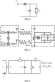
- FIG. 2 illustrates a possible structure of a power harvesting module.
- the power harvesting module 121 may harvest the power of a space electromagnetic wave of a radio frequency signal based on a principle of electromagnetic induction, and store the harvested power in a capacitor C, that is a charging process of the capacitor C.
- the capacitor C may start discharging to supply power for the terminal to work.
- the discharge of the capacitor C may be used to drive the terminal to demodulate the data sent by the network device with low power.
- the discharge of the capacitor C may be used to drive the terminal to modulate the data to be sent by the terminal.
- the discharge of the capacitor C may be used to drive the sensor of the terminal for data acquisition.
- the discharge of the capacitor C may be used to drive the terminal to read data in the memory 125 or the like.
- the above back scattering communication module 122 is used for a back scattering communication between the terminal and the network device.
- a principle of a back scattering communication in the embodiments of the present disclosure is introduced in combination with FIG. 3 below.
- the terminal 120 receives a wireless signal sent by the network device 110 and modulates the wireless signal to load data to be sent. Finally, the modulated signal is radiated from antennas. This information transmission process is called the back scattering communication.
- the back scattering communication and a load modulation function are inseparable.
- the load modulation function may be understood as adjustment and control of circuit parameters of an oscillation loop of the terminal according to a beat of a data flow, so that the magnitude of impedance and other parameters of the terminal change accordingly, so as to complete the modulation process.
- a transport (TX) path for the network device 110 may also be provided with other devices (such as an amplifier (AMP), etc) for processing a signal to be sent.
- a receive (RX) path for the network device 110 may also be provided with other devices (such as a low noise amplifier (LNA), etc) for processing the received signal.
- AMP amplifier
- LNA low noise amplifier
- the terminal 120 may be provided with a power harvesting unit for harvesting the power of the wireless power supply signal sent by the network device.
- a logical processing unit may also be provided in the terminal 120 to perform corresponding calculation functions.
- FIG. 3 only exemplarily illustrates the connection structure of the signal processing circuit, and the processing circuit of the network device 110 and/or the terminal 120 may include other elements, which are not specifically limited in the embodiments of the present disclosure.
- FIG. 4 illustrates a circuit diagram of a terminal based on a resistive load modulation technology. It should be noted that the circuit described in FIG. 4 implements the load modulation technique in a manner similar to that of a conventional circuit for implementing the load modulation technique. For the sake of simplicity, the functions of resistors R 2 and R 3 , capacitors C 1 and C 2 , and inductors L 1 and L 2 included in FIG. 4 will not be described in detail.
- a resistor R L may be connected in parallel with the load.
- a switch S may be used to realize on or off of the resistor R L based on the control of a binary data flow.
- the on or off of the resistor R L will cause a change of a voltage in the circuit, and the change of the voltage in the circuit may control an amplitude of a back scattering signal of the terminal, and then realize the modulation of the back scattering signal, that is, an amplitude-shift keying (ASK) modulation is performed on the back scattering signal.
- ASK amplitude-shift keying
- the capacitor may be controlled to be on and off based on a binary data flow to change a resonant frequency of the circuit, and then change a working frequency of the back scattering signal, so as to realize a frequency-shift keying (FSK) modulation.
- FSK frequency-shift keying
- the terminal may perform information modulation on an incoming wave signal (i.e., the signal sent by network device) in a manner of the load modulation, thus realizing the back scattering communication process. Therefore, the terminal in the back scattering communication usually have the following advantages.
- a first advantage is that because the terminal does not need to send signals actively, construction of a complex radio frequency path is not needed.
- a power amplifier (PA), a radio frequency filter and the like may not be provided in the radio frequency path to reduce the cost and volume of the terminal.
- a second advantage is that because the terminal does not need to generate high-frequency signals actively, a high-frequency crystal oscillator is not needed, so as to reduce the cost and volume of the terminal.
- a third advantage is that because the terminal can communicate with the network device by the back scattering technology, the terminal consumes lower power in communication, or even does not need to consume its own power.
- a decoding end e.g. the network device or a wireless radio frequency identification system
- a decoding end may use a corresponding decoding manner to decode a bitstream sent by the encoding end.
- Coding methods commonly used in the zero-power communication technology include: a non-return zero (NRZ) coding, a Manchester coding, a unipolar RZ coding, a differential binary phase (DBP) coding, a Miller coding, a differential coding and so on.
- FIG. 5 is a schematic diagram of an encoding manner of an NRZ coding. Referring to FIG. 5 , it can be seen that in the NRZ coding, a high level is used to denote a binary "1" and a low level is used to denote a binary "0".
- FIG. 6 is a schematic diagram of an encoding manner of a Manchester coding.
- the Manchester coding is also called a Split-Phase Coding.
- a value of a bit is represented by the change (rise or fall) of a level at half a bit period in a length of the bit.
- a negative jump at half a bit period is a binary "1”
- a positive jump at half of a bit period is a binary "0”.
- the Manchester coding is used commonly for data transmission from an electronic tag to a reader-writer because it facilitates the detection of data transmission errors. This is because a state of "no change" is not allowed within the length of the bit.
- FIG. 7 is a schematic diagram of an encoding manner of a unipolar return-to-zero coding.
- a high level of the unipolar return-to-zero coding in the first half a bit period represents a binary "1"
- a low level signal lasting the whole bit period represents a binary "0”.
- the unipolar return-to-zero coding may be used to extract bit synchronization signals.
- FIG. 8 is a schematic diagram of an encoding manner of a DBP coding. As illustrated in FIG. 8 , any edge of DBP in half a bit period represents a binary "0", while no edge represent a binary "1". In addition, at the beginning of each bit period, the level is inverted. Therefore, it is easier for the receiver to reconstruct a bit beat.
- FIG. 9 is a schematic diagram of the encoding manner of a Miller coding. Referring to FIG. 9 , any edge of the Miller coding within half a bit period represents a binary "1", while a level that is unchanged over a next bit period represents a binary "0". Level alternating occurs at the beginning of the bit period, so that the bit beat is easier to be reconstructed for the receiver.
- each binary "1" to be transmitted causes change of a signal level, while for a binary "0", the signal level remains unchanged.
- terminals may include three types of terminals based on their power sources and power usage: a passive zero-power terminal, a semi-passive zero-power terminal and an active zero-power terminal.
- a passive zero-power terminal usually does not require built-in batteries.
- the terminal When the terminal approaches the network device, the terminal is in a near field range formed by antenna radiations of the network device. At this time, antennas of the terminal may generate an induced current through electromagnetic induction, and the induced current may supply power for the terminal to realize demodulation for the received signal and/or modulation, encoding and the like for the signal to be transmitted.
- the passive zero-power terminal may be an electronic tag, and accordingly, the network device may be a reader-writer of a radio frequency identification (RFID) system for reading contents of the electronic tag and/or for modifying the contents of the electronic tag.
- RFID radio frequency identification
- the semi-passive zero-power terminal itself is not equipped with conventional batteries, but it may harvest radio wave power using a power harvesting module 121 and store the harvested power in a power storage unit (such as a capacitor). After obtaining power, the power storage unit can supply power to the terminal to realize demodulation for the received signal and/or modulation, encoding and the like for the signal to be transmitted.
- a power storage unit such as a capacitor
- the active zero-power terminal may have built-in batteries.
- the batteries may supply power to the terminal to realize demodulation for the received signal and/or modulation, encoding and the like for the signal to be transmitted.
- the terminal device uses the back scattering technology to communicate, the terminal does not need to consume the power of the batteries. Therefore, for this kind of terminal, "zero-power consumption" is mainly reflected in the scene where the terminal uses the back scattering technology to communicate.
- the active zero-power terminal may be an electronic tag
- the network device may be an RFID reader-writer.
- the built-in batteries may supply power to an RFID chip in the terminal to increase a reading and writing distance between the RFID reader-writer and the electronic tag.
- the built-in batteries may supply power to the RFID chip in the terminal, so as to shorten a delay of reading and writing the electronic tag by the RFID reader-writer, which is beneficial to improve the reliability of communication.
- the zero-power terminal usually needs to obtain power based on the wireless power supply signal sent by the network device before communication.
- a conservative sending duration is usually predefined for the network device to send the wireless power supply signal.
- the power required by different terminals may not be the same.
- the terminal may obtain enough power through the wireless power supply signal after a time period shorter than the conservative sending duration. At this time, if the wireless power supply signal was still sent for the conservative sending duration, resources will be wasted. On the other hand, for the terminal with less power required, the terminal can obtain enough power after the time period shorter than the conservative sending duration. If the network device still sends the wireless power supply signal according to the conservative sending duration, the power of the network device will be wasted. On the other hand, for the terminal with less power required, the terminal can obtain enough power after the time period shorter than the conservative sending duration. If the network device still sends the wireless power supply signal according to the conservative sending duration, it may cause interference to other signals.
- the present disclosure provides a communication method in which the terminal may send a wireless power supply parameter to the network device to indicate a power required by the terminal to the network device, so that the network device can determine the sending duration of the wireless power supply signal based on the wireless power supply parameter.
- the wireless power supply parameter is used to refer to a class of information having the above functions or including various parameters described below.
- the class of information having the above functions or including various parameters described below may also be parameters or information with other names specified in future agreements. Embodiments of the present disclosure are not limited thereto.
- the above wireless power supply parameter includes one or more of the following parameters: power harvesting efficiency of the terminal, a power harvesting speed of the terminal, harvesting time required by the terminal for harvesting a preset power, and a signal strength of a signal received by the terminal.
- the above parameters will be introduced one by one below.
- a first parameter is the harvesting time required by the terminal for acquiring the preset power.
- the preset power may be understood as the power required for the normal operation of the terminal.
- the normal operation of the terminal may include, for example, one or more of operations of receiving a signal, demodulating a signal, modulating a signal, encoding a signal, etc. by the terminal.
- the harvesting time required by the terminal for acquiring the preset power may be understood as harvesting time required by the terminal to complete the harvesting of the preset power when the network device sends the wireless power supply signal.
- the preset power corresponding to different terminals may be different, and the preset power of a terminal may be related to a type, a working condition and hardware parameters of the terminal.
- the hardware parameters of the terminal may be parameters of the power harvesting module (also called "a power receiver") of the terminal.
- the harvesting time may be pre-configured in the terminal by testing before the terminal leaves a factory.
- the harvesting time of the terminal may change with the working condition of the power harvesting module or with the working condition of the terminal.
- the terminal may calculate the harvesting time by itself. For example, the terminal may determine the harvesting time based on historical wireless power supply signals.
- the manner in which the terminal obtains the harvesting time is not limited thereto.
- a second parameter is the power harvesting efficiency of the terminal.
- the power harvesting efficiency of the terminal may be characterized by a ratio between a power of a signal when the signal arrives at the terminal and a power of a signal obtained by the terminal when the signal is acquired.
- the power harvesting efficiency will affect the power harvesting time, and then affect the sending duration of the wireless power supply signal. For example, for a terminal with higher power harvesting efficiency, time required to harvest enough power is shorter, and accordingly, the sending duration of the wireless power supply signal will be shorter. For another example, for a terminal with lower power harvesting efficiency, time required to harvest enough power is longer, and accordingly, the sending duration of the wireless power supply signal will be longer.
- a signal strength of a wireless power supply signal when the wireless power supply signal arrives at the terminal will also affect the time required for the terminal to harvest enough power.
- the power harvesting efficiency of the terminal is constant, the closer the terminal is from the network device, the stronger the power of the wireless power supply signal received by the terminal is, and the more the power of the wireless power supply signal will be harvested by the terminal, so that the terminal can obtain enough power in shorter time.
- the normal operation of the terminal may include, for example, one or more of the operations of receiving a signal, demodulating a signal, modulating a signal, encoding a signal, etc. by the terminal.
- the power harvesting efficiency of the terminal is not fixed.
- the power of the wireless power supply signal is 100 milliwatts when it arrives at the terminal, the power harvesting efficiency of the terminal may be 50%.
- the power of the wireless power supply signal is 20 milliwatts when it reaches the terminal, the power harvesting efficiency of the terminal may be 20%. Therefore, the terminal calculates its own power harvesting efficiency in real time, which is beneficial to improve the accuracy of determining the sending duration of wireless power supply signal.
- the power harvesting efficiency of different terminals may be different, and the power harvesting efficiency of a terminal may be related to the type, working condition and hardware parameters of the terminal.
- the hardware parameters of the terminal may be parameters of the power harvesting module (also called "a power receiver") of the terminal.
- the power harvesting efficiency of the terminal may be pre-configured in the terminal by testing before the terminal leaves a factory.
- the power harvesting efficiency of the terminal may also be calculated in real time by the terminal based on historical data.
- the power harvesting efficiency of the terminal may be determined by the terminal based on a ratio between a power of the historical wireless power supply signal arriving at the terminal and a power obtained by the terminal performing harvesting on the signal. There is no limit made to the manner in which the terminal obtains the power harvesting efficiency in the embodiments of the present disclosure.
- a third parameter is the power harvesting speed of the terminal.
- the power harvesting speed of the terminal may be characterized by the power obtained by the terminal performing harvesting of the wireless power supply signal in unit time.
- the power harvesting speed will affect the power harvesting time, and then affect the sending duration of the wireless power supply signal. For example, for a terminal with higher power harvesting speed, the time required to harvest enough power is shorter, and accordingly, the sending duration of the wireless power supply signal will be shorter. For another example, for a terminal with lower power harvesting speed, the time required to harvest enough power is longer, and accordingly, the sending duration of the wireless power supply signal will be longer.
- the signal strength of a wireless power supply signal when it arrives at the terminal will also affect the time required for the terminal to harvest enough power.
- the power harvesting speed of the terminal is constant, if the terminal is closer to the network device, the power of the wireless power supply signal received by the terminal is stronger, and the power of the wireless power supply signal will be harvested by the terminal, so that the terminal can obtain enough power in shorter time.
- the normal operation of the terminal may include, for example, one or more of the operations of receiving a signal, demodulating a signal, modulating a signal, encoding a signal, etc. by the terminal.
- the power harvesting speed of different terminals may be different, and the power harvesting speed of a terminal may be related to the type, working condition and hardware parameters of the terminal.
- the hardware parameters of the terminal may be parameters of the power harvesting module (also called "a power receiver") of the terminal.
- the power harvesting speed of the terminal may be pre-configured in the terminal by testing before the terminal leaves a factory.
- the power harvesting speed of the terminal may also be calculated in real time by the terminal based on historical data.
- the terminal may determine the power harvesting speed of the terminal based on a total power obtained by power harvesting of historical wireless power supply signals in unit time. There is no limit made to the manner in which the terminal obtains the power harvesting speed in the embodiments of the present disclosure.
- a fourth parameter is the signal strength of the signal received by the terminal.
- the signal received by the terminal may be understood as a signal sent by the network device to the terminal, and the network device may be a network device that needs to send the wireless power supply signal to the terminal.
- the signal strength of the signal received by the terminal will affect the power harvesting time of the terminal, and then affect the sending duration of the wireless power supply signal. For example, if the signal strength of the signal received by the terminal is higher, the time required for the terminal to harvest enough power is shorter, and accordingly, the sending duration of the wireless power supply signal will be shorter. For another example, if the signal strength of the signal received by the terminal is lower, the time required for the terminal to harvest enough power is longer, and accordingly, the sending duration of the wireless power supply signal will be longer.
- the normal operation of the terminal may include, for example, one or more of the operations of receiving a signal, demodulating a signal, modulating a signal, encoding a signal, etc. by the terminal.
- the signal strength may be calculated by the terminal in real time based on historical data.
- the terminal may detect the historical signal sent by the network device to determine the signal strength.
- the above signal strength may also be sent to the terminal by another terminal, where the distance between another terminal and the network device is similar to the distance between the terminal and network device. There is no limit made to the manner in which the terminal obtains the signal strength in the embodiments of the present disclosure.
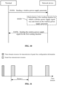
- the communication method described in FIG. 10 includes an operation S 1010.
- the terminal sends the wireless power supply parameter to the network device.
- the terminal may send a wireless power supply parameter to the network device to indicate the power required by the terminal to the network device, so that the network device may determine a sending duration of the wireless power supply signal based on the wireless power supply parameter, which is beneficial to improving the utilization rate of resources in the communication system.
- the problem of resource waste caused by the network device sending the wireless power supply signal according to a sending duration corresponding to a power that exceeds the power required by the terminal that is, a conservative sending duration) in the traditional transmission process of the wireless power supply signal is avoided.
- the wireless power supply parameter may be carried in a radio resource control (RRC) signaling. In other implementations, the wireless power supply parameter may be carried in a medium access control (MAC) control element (CE).
- RRC radio resource control
- MAC medium access control
- the network device may determine the first sending duration of the wireless power supply signal based on the wireless power supply parameter. That is, the method further includes operations S 1020 to S 1030.
- the network device determines the first sending duration for which the wireless power supply signal was sent based on the wireless power supply parameter.
- the network device may determine the first sending duration based on the received wireless power supply parameter, and a relationship between preset wireless power supply parameters and sending durations.
- the relationship between the preset wireless power supply parameters and the sending durations may be, for example, a functional relationship. Accordingly, the network device calculates the first sending duration based on the received wireless power supply parameter and the functional relationship.
- the relationship between the preset wireless power supply parameters and the sending durations may be, for example, a mapping table. In the mapping table, wireless power supply parameters may be divided into several levels, and different levels correspond to different sending durations. Thus, the network device may determine a corresponding level based on the received wireless power supply parameter and determine the first sending duration based on the corresponding level.
- the network device sends a wireless power supply signal to the terminal for a first sending duration.
- the sending duration of the wireless power supply signal sent by the network device may be slightly longer than the first sending duration.
- the network device may send the wireless power supply signal for a second sending duration, where the second sending duration is longer than the first sending duration.
- the network device may send the wireless power supply signal by using the same sending duration in the longer period of time.
- the effective duration of the wireless power supply parameter sent by the terminal is shorter, or the wireless power supply parameter of the terminal is changeable.
- the terminal needs to report the wireless power supply parameter in real time along with the position movement, so that the network device can update the sending duration of the wireless power supply parameter in real time.
- the terminal may only send the wireless power supply parameter to the network device once before the next movement.
- the terminal may also send the wireless power supply parameter periodically to the network device in a longer period.
- the terminal may send the wireless power supply parameter periodically to the network device in a shorter period.
- the terminal may determine the time when the wireless power supply parameter is to the network device according to a change degree of the wireless power supply parameter. For example, when the terminal detects that the change degree of the wireless power supply parameter is higher than a threshold, the terminal sends a changed wireless power supply parameter to the network device. Accordingly, when the terminal detects that the change degree of the wireless power supply parameter is lower than the threshold, the terminal does not send the changed wireless power supply parameter to the network device.
- the data to be transmitted between the terminal and the network device (for example, service data) is periodic, and a data amount of the data transmitted in each period is fixed relatively.
- the data to be transmitted may be sent from the terminal to the network device or from the network device to the terminal.
- the terminal usually reports environmental monitoring data to the network device periodically according to a certain service period, and the data amount of the environmental monitoring data is relatively fixed.
- the terminal usually reports industrial monitoring data to the network device periodically according to a certain service period, and the data amount of industrial monitoring data is fixed relatively.
- the terminal may transmit data in a manner of grant free transmission.
- the network device may configure a configuration signaling for the grant free transmission to the terminal at one time, and accordingly, the terminal may transmit data periodically on the configured resources in the manner of grant free transmission based on the configuration signaling.
- the network device does not need to schedule the terminal in the process of data transmission of the terminal.
- the terminal cannot perform grant free transmission autonomously even if the network device sends the configuration signaling for the grant free transmission to the terminal.
- the present disclosure also provides a communication method.
- the network device may provide power for the terminal to perform grant free transmission by sending a wireless power supply signal to the terminal, so that the terminal can perform grant free transmission, thereby reducing the overhead generated by the network device configuring resources for transmitting data for the terminal.
- a communication method of another embodiment of the present disclosure will be described below with reference to FIG. 12 .
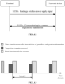
- FIG. 12 is a flow diagram of a communication method provided by another embodiment of the present disclosure. The method illustrated in FIG. 12 includes operations S1210 to S1220.
- the network device sends a wireless power supply signal to the terminal.
- the network device may send the wireless power supply signal to the terminal using the method illustrated in FIG. 10 .
- the network device may also send the wireless power supply signal to the terminal in a traditional manner.
- the terminal communicates with the network device in a manner of grant free transmission.
- the operation that the terminal communicates with the network device in the manner of the grant free transmission may include that the terminal sends data to the network device in the manner of the grant free transmission, or receives data from the network device in the manner of the grant free transmission.
- the wireless power supply signal is transmitted periodically, and a period for transmission of the wireless power supply signal is the same as a period for grant free transmission.
- the network device occupies a time domain resource 1 to transmit configuration information for grant free transmission to the terminal, and the configuration information is used to configure the terminal to perform grant free transmission on a grant free transmission resource according to a period 1.
- the network device also takes period 1 as a period and occupies a target time domain resource before the grant free resource to send the wireless power supply signal to the terminal.
- the terminal receives the wireless power supply signal on the target time domain resource to obtain power, and receives or transmits data on the grant free resource after the target time domain resource.
- a last time domain symbol of the target time domain resource may be adjacent to a first symbol of the grant free resource, so that the terminal can send and receive data immediately after obtaining enough power through the wireless power supply signal.
- the last time domain symbol of the target time domain resource and the first symbol of the grant free resource may not be adjacent, for example, separated by several symbols therebetween, so as to reserve some time for the terminal to perform signal processing or obtain data to be transmitted after the terminal obtains enough power.
- the embodiments of the present disclosure do not specifically limit the positional relationship between the target time domain resource and the grant free resource.
- signal processing by the terminal may include encoding the data to be sent by the terminal. Signal processing by the terminal may also include modulating the data to be sent by the terminal. In other implementations, obtaining data to be transmitted by the terminal may for example include harvesting of data to be transmitted by the terminal through a sensing device.
- the zero-power communication terminal described above is usually in a power-off state (or sleep state) when it does not communicate with the network device (for example, it does not need to receive data sent by the network device or send data to the network device). At this time, the terminal does not have enough power to maintain a clock.
- the terminal When the terminal is awakened from the sleep state and receives or sends data, the terminal usually cannot synchronize with the network device. In this way, the data cannot be transmitted correctly between the terminal and the network device.
- the network device may send a synchronization signal or a synchronization channel to the terminal when transmitting data, so that the terminal is synchronized with the network device.
- a position of a time domain resource occupied by the synchronization signal or the synchronization channel may be located after a position of a time domain resource occupied by the wireless power supply signal.
- the network device may send the synchronization signal or the synchronization channel to the terminal.
- the synchronization channel or synchronization signal may be included in the wireless power supply signal, in which case the terminal may synchronize with the network device while receiving the wireless power supply signal.
- the synchronization channel is used to carry an index of a time unit, which may for example be a slot or a sub-frame.
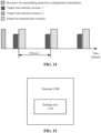
- the synchronization process of an embodiment of the present disclosure is described below with reference to FIG. 14 taking a grant free scenario as an example. It is assumed that the network device occupies a time domain resource 1 to transmit configuration information for grant free transmission to the terminal, and the configuration information is used to configure the terminal to perform grant free transmission on a grant free transmission resource according to a period 1. In addition, the network device occupies the target time domain resource 1 to send the wireless power supply signal for the terminal, and occupies the target time domain resource 2 to send the synchronization signal for the terminal.
- the target time domain resource 1 and the target time domain resource 2 are transmission resources configured periodically, where a period for the configuration is also period 1.
- a position of a time domain of the target time domain resource 1 is located before a position of a time domain of the target rime domain resource 2.
- the position of the time domain of the target time domain resource 2 is located before a position of a time domain of the grant free transmission resource.
- the terminal receives a wireless power supply signal on the target time domain resource 1 to obtain power, receives a synchronization signal on the target time domain resource 2 to synchronize with the network device, and receives or sends data on the grant free resource.
- a last time domain symbol of the target time domain resource 2 may be adjacent to the first symbol of the grant free resource, so that the terminal can send and receive data immediately after synchronizing with the network device through the synchronization signal.
- the last time domain symbol of the target time domain resource 2 and the first symbol of the grant free resource may not be adjacent, for example, separated by several symbols therebtween, so that sufficient time can be reserved for synchronization between the terminal and the network device. There is no limit made thereto in the embodiments of the present disclosure.
- the last time domain symbol of the target time domain resource 1 may be adjacent to a first symbol of the target time domain resource 2, so that the terminal can synchronize immediately based on the synchronization signal after obtaining enough power through the wireless power supply signal.
- the last time domain symbol of the target time domain resource 1 and the first symbol of the target time domain resource 2 may not be adjacent, for example, separated by several symbols therebetween, so as to reserve time for synchronization of the terminal. There is no limit made thereto in the embodiments of the present disclosure.
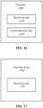
- FIG. 15 illustrates a schematic diagram of a terminal according to an embodiment of the present disclosure. As illustrated in FIG. 15 , the terminal 1500 includes a sending unit 1510.
- the sending unit 1510 is configured to send a wireless power supply parameter.
- the wireless power supply parameter includes one or more of the following parameters: power harvesting efficiency of the terminal; a power harvesting speed of the terminal; harvesting time required by the terminal for acquiring a preset power; or a signal strength of a signal received by the terminal.
- the terminal further includes: a first receiving unit.
- the first receiving unit is configured to receive a wireless power supply signal that was sent by a network device for a first sending duration.
- the first sending duration is determined based on the wireless power supply parameter.
- the wireless power supply signal is a signal transmitted periodically, and a period for transmission of the wireless power supply signal is the same as a period for grant free transmission.
- the wireless power supply signal includes a first synchronization signal or a first synchronization channel.
- the terminal further includes: a first processing unit.
- the first processing unit is configured to perform synchronization with the network device based on the first synchronization signal or the first synchronization channel.
- the terminal further includes: a second receiving unit and a second processing unit.
- the second receiving unit is configured to receive a second synchronization signal or a second synchronization channel sent by the network device, where a position of a time domain resource occupied by the second synchronization signal or the second synchronization channel is located after a position of a time domain resource occupied by the wireless power supply signal.
- the second processing unit is configured to perform synchronization with the network device based on the second synchronization signal or the second synchronization channel.
- the sending unit is configured to send indication information to a network device, where the indication information is used to indicate that the terminal is in a stationary state or in a moving state.
- the wireless power supply parameter is carried in a radio resource control (RRC) signaling or a medium access control (MAC) control unit (CE).
- RRC radio resource control
- MAC medium access control
- FIG. 16 illustrates a schematic diagram of a terminal according to another embodiment of the present disclosure.
- the terminal 1600 includes a receiving unit 1610 and a communication unit 1620.
- the receiving unit 1610 is configured to receive a wireless power supply signal sent by a network device.
- the communication unit 1620 is configured to send data to the network device in a manner of grant free transmission, or receive data from the network device in the manner of the grant free transmission.
- the wireless power supply signal includes a first synchronization signal or a first synchronization channel.
- the terminal further includes: a first processing unit.
- the first processing unit is configured to perform synchronization with the network device based on the first synchronization signal or the first synchronization channel.
- the receiving unit is configured to receive a second synchronization signal or a second synchronization channel sent by the network device, where a position of a time domain resource occupied by the second synchronization signal or the second synchronization channel is located after a position of a time domain resource occupied by the wireless power supply signal.
- the terminal further includes a second processing unit, and the second processing unit is configured to perform synchronization with the network device based on the second synchronization signal or the second synchronization channel.
- the wireless power supply signal is a signal transmitted periodically, and a period for transmission of the wireless power supply signal is the same as a period for grant free transmission.
- the first synchronization channel is used to carry an index of a time unit.
- the second synchronization channel is used to carry an index of a time unit.
- FIG. 17 is a schematic diagram of a network device according to an embodiment of the present disclosure. As illustrated in FIG. 17 , the network device 1700 includes a receiving unit 1710.
- the receiving unit 1710 is configured to receive a wireless power supply parameter of a terminal.
- the wireless power supply parameter includes one or more of the following parameters: power harvesting efficiency of the terminal; a power harvesting speed of the terminal; harvesting time required by the terminal for acquiring a preset power; or a signal strength of a signal received by the terminal.
- the network device further includes a processing unit and a first sending unit.
- the processing unit is configured to determine a first sending duration for which a wireless power supply signal was sent based on the wireless power supply parameter.
- the first sending unit is configured to send the wireless power supply signal to the terminal for the first sending duration.
- the terminal transmits data in a manner of grant free transmission
- the wireless power supply signal is a signal transmitted periodically, and a period for transmission of the wireless power supply signal is the same as a period for the grant free transmission.
- the wireless power supply signal includes a first synchronization signal or a first synchronization channel.
- the network device further includes a second sending unit.
- the second sending unit is configured to send a second synchronization signal or a second synchronization channel to the terminal.
- a position of a time domain resource occupied by the second synchronization signal or the second synchronization channel is located after a position of a time domain resource occupied by the wireless power supply signal.
- the receiving unit is configured to receive indication information sent by the terminal.
- the indication information is used to indicate that the terminal is in a stationary state or in a moving state.
- the wireless power supply parameter is carried in an RRC signaling or an MAC CE.
- FIG. 18 is a schematic diagram of a network device according to another embodiment of the present disclosure. As illustrated in FIG. 18 , the network device 1800 includes a sending unit 1810 and a communication unit 1820.
- the sending unit 1810 is configured to send a wireless power supply signal to a terminal.
- the communication unit 1820 is configured to receive data that is sent by the terminal in a manner of grant free transmission, or send data to the terminal in the manner of the grant free transmission.
- the wireless power supply signal includes a first synchronization signal or a first synchronization channel.
- the second sending unit is configured to send a second synchronization signal or a second synchronization channel to the terminal.
- a position of a time domain resource occupied by the second synchronization signal or the second synchronization channel is located after a position of a time domain resource occupied by the wireless power supply signal.
- the wireless power supply signal is a signal transmitted periodically, and a period for transmission of the wireless power supply signal is the same as a period for grant free transmission.
- the first synchronization channel is used to carry an index of a time unit.
- the second synchronization channel is used to carry an index of a time unit.
- FIG. 19 is a schematic structural diagram of a communication apparatus according to an embodiment of the present disclosure.
- the dotted line in FIG. 19 indicates that the unit or module is optional.
- the apparatus 1900 may be used to implement the methods described in the above method embodiments.
- the apparatus 1900 may be a chip, a terminal device or a network device.
- the apparatus 1900 may include one or more processors 1910.
- the processor 1910 may support the apparatus 1900 to implement the methods described previously in the method embodiments.
- the processor 1910 may be a general purpose processor or a special-purpose processor.
- the processor may be a central processing unit (CPU).
- the processor may be another general purpose processor, a digital signal processor (DSP), an application specific integrated circuit (ASIC), a field programmable gate array (FPGA) or other programmable logic devices, discrete gates or transistor logic devices, or discrete hardware components.
- DSP digital signal processor
- ASIC application specific integrated circuit
- FPGA field programmable gate array
- the general purpose processor may be a microprocessor or any conventional processor.
- the apparatus 1900 may further include one or more memories 1920.
- the memory 1920 stores a program that may be executed by processor 1910 such that the processor 1910 performs the methods described previously in the method embodiments.
- the memory 1920 may be independent of the processor 1910 or may be integrated within the processor 1910.
- the apparatus 1900 may also include a transceiver 1930.
- the processor 1910 may communicate with other devices or chips through the transceiver 1930.
- the processor 1910 may transmit and receive data with other devices or chips via the transceiver 1930.
- a computer-readable storage medium configured to store a program.
- the computer-readable storage medium may be applied to the terminal or the network device provided by the embodiments of the present disclosure, and the program causes a computer to perform the method implemented by the terminal or the network device in various embodiments of the present disclosure.
- a computer program product includes a program.
- the computer program product may be applied to the terminal or the network device provided by the embodiments of the present disclosure, and the program causes a computer to perform the method implemented by the terminal or the network device in various embodiments of the present disclosure.
- a computer program there is further provided a computer program.
- the computer program may be applied to the terminal or the network device provided by the embodiments of the present disclosure, and the computer program causes a computer to perform the method implemented by the terminal or the network device in various embodiments of the present disclosure.
- the "indicate” mentioned in the embodiments of the present disclosure may be a direct indication, may be an indirect indication, or may indicate an association relationship.
- a indicates B which may mean that A directly indicates B, for example, B may be obtained through A. It may also mean that A indirectly indicates B, for example, A indicates C, and B may be obtained by C. It may also indicate that there is an association relationship between A and B.
- B corresponding to A means that B is associated with A, and B may be determined based on A. It should also be understood, however, that determining B based on A does not mean determining B based on A alone, but may also mean determining B based on A and/or other information.
- the term "correspond” may mean that there is a direct correspondence or an indirect correspondence relationship between the two, or may also mean that there is an association relationship between the two, or may also be a relationship between indication and being indicated, configuration and being configured, etc.
- predefined or “pre-configured” may be implemented by pre-storing corresponding codes, tables, or other manners that may be used to indicate relevant information in devices (e.g., including terminal devices and network devices), the specific implementation of which is not limited by the present disclosure.
- predefined may refer to being defined in the protocol.
- the "protocol” may refer to standard protocols in the communication field, such as LTE protocol, NR protocol, and related protocols applied in future communication systems, which are not limited herein.
- the term "and/or" is used to describe an association relationship of associated objects, and represents that there may be three relationships.
- a and/or B may represent the following three situations: i.e., independent existence of A, existence of both A and B and independent existence of B.
- the character "/" in the present disclosure generally represents that an "or" relationship is formed between the previous and next associated objects.
- the size of the sequence numbers of the above processes does not mean the order of execution, and the execution order of each process should be determined by its function and inherent logic, and should not construct any limitation to the implementation process of the embodiments of the present disclosure.
- the disclosed systems, apparatuses and methods may be implemented in other manners.
- the above-described embodiments of the apparatus are only schematic, for example, the division of the units is only a logical function division, and in practice, there may be another division manner, for example, multiple units or components may be combined or integrated into another system, or some features may be ignored or not performed.
- the coupling or direct coupling or communication connection between each other illustrated or discussed may be indirect coupling or communication connection through some interfaces, devices or units, and may be electrical, mechanical or other form.
- the units illustrated as separate elements may or may not be physically separated, and the elements displayed as units may or may not be physical units, i.e. may be located in a place, or may be distributed over a plurality of network units. Part or all of the units may be selected according to the actual needs to achieve the purpose of the embodiments of the present disclosure.
- each functional unit in each embodiment of the present disclosure may be integrated in one processing unit, each unit may exist physically alone, or two or more units may be integrated in one unit.
- the computer program product includes one or more computer instructions.
- the computer may be a general purpose computer, a special purpose computer, a computer network, or other programmable device.
- the computer instructions may be stored in a computer-readable storage medium, or transmitted from one computer-readable storage medium to another.
- the computer instructions may be transmitted from a web site, computer, server, or data center to another web site, computer, server, or data center via wired (e.g. coaxial cable, optical fiber, digital subscriber line (DSL)) or wireless (e.g. infrared, wireless, microwave, etc.).
- the computer-readable storage medium may be any usable medium that a computer may read or a data storage device containing one or more usable media integration, such as a server, data center, etc.
- the usable medium may be a magnetic medium (e.g. floppy disk, hard disk, magnetic tape), an optical medium (e.g. digital video disc (DVD)), or a semiconductor medium (e.g. solid state disk (SSD)), etc.
Landscapes
- Engineering & Computer Science (AREA)
- Computer Networks & Wireless Communication (AREA)
- Signal Processing (AREA)
- Power Engineering (AREA)
- Mobile Radio Communication Systems (AREA)
Applications Claiming Priority (1)
| Application Number | Priority Date | Filing Date | Title |
|---|---|---|---|
| PCT/CN2021/118353 WO2023039730A1 (zh) | 2021-09-14 | 2021-09-14 | 通信方法、终端及网络设备 |
Publications (2)
| Publication Number | Publication Date |
|---|---|
| EP4404642A1 true EP4404642A1 (de) | 2024-07-24 |
| EP4404642A4 EP4404642A4 (de) | 2025-07-30 |
Family
ID=85602241
Family Applications (1)
| Application Number | Title | Priority Date | Filing Date |
|---|---|---|---|
| EP21957021.5A Pending EP4404642A4 (de) | 2021-09-14 | 2021-09-14 | Kommunikationsverfahren, endgerät und netzwerkvorrichtung |
Country Status (4)
| Country | Link |
|---|---|
| US (1) | US20240259939A1 (de) |
| EP (1) | EP4404642A4 (de) |
| CN (1) | CN117941424A (de) |
| WO (1) | WO2023039730A1 (de) |
Families Citing this family (2)
| Publication number | Priority date | Publication date | Assignee | Title |
|---|---|---|---|---|
| WO2025009778A1 (ko) * | 2023-07-06 | 2025-01-09 | 엘지전자 주식회사 | 무선 통신 시스템에서 하베스팅 주기에 기반한 포지셔닝 수행 방법 및 이를 위한 장치 |
| CN121418989A (zh) * | 2024-07-26 | 2026-01-27 | 华为技术有限公司 | 信息传输的方法和通信装置 |
Family Cites Families (5)
| Publication number | Priority date | Publication date | Assignee | Title |
|---|---|---|---|---|
| JP2014220944A (ja) * | 2013-05-09 | 2014-11-20 | キヤノン株式会社 | 給電装置、電子機器、方法及びプログラム |
| CN108565938B (zh) * | 2018-03-22 | 2021-06-01 | 宁波大学 | 一种无线充电控制方法 |
| CN108718466B (zh) * | 2018-05-18 | 2020-10-23 | 南京启纬智芯微电子有限公司 | 无线供能设备、无源电子设备、无线通信方法及系统 |
| CN109413731B (zh) * | 2018-11-19 | 2020-09-29 | 北京邮电大学 | 一种无线供能的信息传输与接收方法 |
| WO2021155209A1 (en) * | 2020-01-30 | 2021-08-05 | Idac Holdings, Inc. | Methods, apparatus, and systems for operational procedures supporting a zero-energy air-interface |
-
2021
- 2021-09-14 EP EP21957021.5A patent/EP4404642A4/de active Pending
- 2021-09-14 WO PCT/CN2021/118353 patent/WO2023039730A1/zh not_active Ceased
- 2021-09-14 CN CN202180102200.6A patent/CN117941424A/zh active Pending
-
2024
- 2024-03-12 US US18/602,809 patent/US20240259939A1/en active Pending
Also Published As
| Publication number | Publication date |
|---|---|
| US20240259939A1 (en) | 2024-08-01 |
| WO2023039730A1 (zh) | 2023-03-23 |
| CN117941424A (zh) | 2024-04-26 |
| EP4404642A4 (de) | 2025-07-30 |
Similar Documents
| Publication | Publication Date | Title |
|---|---|---|
| US20250023589A1 (en) | Wireless communication method and device | |
| US20240259939A1 (en) | Communication method, terminal, and network device | |
| US20250071676A1 (en) | Communication method and communications apparatus | |
| US20250039727A1 (en) | Communication method and communications apparatus | |
| WO2023010321A1 (zh) | 一种无线通信方法及装置、通信设备 | |
| US20250212205A1 (en) | Communication method and communications apparatus | |
| US20250008496A1 (en) | Method for determining time domain resource, terminal device, and network device | |
| US20250106084A1 (en) | Communication method, communication device, computer readable storage medium, and chip | |
| WO2025055052A1 (zh) | 信息传输方法、装置、设备、介质和程序产品 | |
| US20250008497A1 (en) | Method for configuring resources, terminal, and network device | |
| EP4676130A1 (de) | Verfahren zur drahtlosen kommunikation sowie endgerätevorrichtung und netzwerkvorrichtung | |
| WO2025010543A1 (zh) | 无线通信的方法、终端设备以及通信设备 | |
| WO2025171666A1 (zh) | 无线通信方法及通信设备 | |
| US20260005813A1 (en) | Wireless communication method and device | |
| US20240163004A1 (en) | Wireless communication method, terminal device and network device | |
| WO2025171671A1 (zh) | 无线通信方法、通信设备、装置以及存储介质 | |
| WO2025166513A1 (zh) | 无线通信方法、通信设备、装置以及存储介质 | |
| WO2025227280A1 (zh) | 用于无线通信的方法及通信设备 | |
| WO2025189461A1 (zh) | 无线通信的方法及通信设备 | |
| WO2025208445A1 (zh) | 无线通信方法、通信设备以及网络设备 | |
| WO2025171663A1 (zh) | 无线通信的方法及通信设备 | |
| WO2025166649A1 (zh) | 传输方法、装置、设备、介质和程序产品 | |
| WO2025160897A1 (zh) | 无线通信方法、通信设备、装置以及存储介质 | |
| WO2025166724A1 (zh) | 无线通信方法及通信设备 | |
| WO2026020473A1 (zh) | 无线通信的方法及通信设备 |
Legal Events
| Date | Code | Title | Description |
|---|---|---|---|
| STAA | Information on the status of an ep patent application or granted ep patent |
Free format text: STATUS: THE INTERNATIONAL PUBLICATION HAS BEEN MADE |
|
| PUAI | Public reference made under article 153(3) epc to a published international application that has entered the european phase |
Free format text: ORIGINAL CODE: 0009012 |
|
| STAA | Information on the status of an ep patent application or granted ep patent |
Free format text: STATUS: REQUEST FOR EXAMINATION WAS MADE |
|
| 17P | Request for examination filed |
Effective date: 20240314 |
|
| AK | Designated contracting states |
Kind code of ref document: A1 Designated state(s): AL AT BE BG CH CY CZ DE DK EE ES FI FR GB GR HR HU IE IS IT LI LT LU LV MC MK MT NL NO PL PT RO RS SE SI SK SM TR |
|
| DAV | Request for validation of the european patent (deleted) | ||
| DAX | Request for extension of the european patent (deleted) | ||
| REG | Reference to a national code |
Ref country code: DE Ref legal event code: R079 Free format text: PREVIOUS MAIN CLASS: H04W0052040000 Ipc: H02J0050000000 |
|
| A4 | Supplementary search report drawn up and despatched |
Effective date: 20250701 |
|
| RIC1 | Information provided on ipc code assigned before grant |
Ipc: H02J 50/00 20160101AFI20250625BHEP Ipc: H04W 52/02 20090101ALI20250625BHEP Ipc: H02J 50/20 20160101ALI20250625BHEP Ipc: H02J 50/80 20160101ALI20250625BHEP |