EP4404591A1 - Système auditif binaural comportant deux instruments auditifs ainsi que procédé de fonctionnement d'un tel système auditif - Google Patents
Système auditif binaural comportant deux instruments auditifs ainsi que procédé de fonctionnement d'un tel système auditif Download PDFInfo
- Publication number
- EP4404591A1 EP4404591A1 EP24152467.7A EP24152467A EP4404591A1 EP 4404591 A1 EP4404591 A1 EP 4404591A1 EP 24152467 A EP24152467 A EP 24152467A EP 4404591 A1 EP4404591 A1 EP 4404591A1
- Authority
- EP
- European Patent Office
- Prior art keywords
- parameter
- signal
- hearing
- hearing instrument
- latency
- Prior art date
- Legal status (The legal status is an assumption and is not a legal conclusion. Google has not performed a legal analysis and makes no representation as to the accuracy of the status listed.)
- Pending
Links
Images
Classifications
-
- H—ELECTRICITY
- H04—ELECTRIC COMMUNICATION TECHNIQUE
- H04R—LOUDSPEAKERS, MICROPHONES, GRAMOPHONE PICK-UPS OR LIKE ACOUSTIC ELECTROMECHANICAL TRANSDUCERS; ELECTRIC HEARING AIDS; PUBLIC ADDRESS SYSTEMS
- H04R25/00—Electric hearing aids
- H04R25/55—Electric hearing aids using an external connection, either wireless or wired
- H04R25/552—Binaural
-
- H—ELECTRICITY
- H04—ELECTRIC COMMUNICATION TECHNIQUE
- H04R—LOUDSPEAKERS, MICROPHONES, GRAMOPHONE PICK-UPS OR LIKE ACOUSTIC ELECTROMECHANICAL TRANSDUCERS; ELECTRIC HEARING AIDS; PUBLIC ADDRESS SYSTEMS
- H04R25/00—Electric hearing aids
- H04R25/50—Customised settings for obtaining desired overall acoustical characteristics
- H04R25/505—Customised settings for obtaining desired overall acoustical characteristics using digital signal processing
-
- H—ELECTRICITY
- H04—ELECTRIC COMMUNICATION TECHNIQUE
- H04R—LOUDSPEAKERS, MICROPHONES, GRAMOPHONE PICK-UPS OR LIKE ACOUSTIC ELECTROMECHANICAL TRANSDUCERS; ELECTRIC HEARING AIDS; PUBLIC ADDRESS SYSTEMS
- H04R2225/00—Details of deaf aids covered by H04R25/00, not provided for in any of its subgroups
- H04R2225/43—Signal processing in hearing aids to enhance the speech intelligibility
-
- H—ELECTRICITY
- H04—ELECTRIC COMMUNICATION TECHNIQUE
- H04R—LOUDSPEAKERS, MICROPHONES, GRAMOPHONE PICK-UPS OR LIKE ACOUSTIC ELECTROMECHANICAL TRANSDUCERS; ELECTRIC HEARING AIDS; PUBLIC ADDRESS SYSTEMS
- H04R2430/00—Signal processing covered by H04R, not provided for in its groups
- H04R2430/03—Synergistic effects of band splitting and sub-band processing
Definitions
- the invention relates to a binaural hearing system with two hearing instruments, which are to be worn by a user on the left ear and the right ear respectively.
- the invention further relates to a method for operating such a hearing system.
- a hearing instrument is generally an electronic device that supports the hearing of a person wearing the hearing instrument (hereinafter referred to as the "wearer” or “user”).
- the invention relates to hearing instruments that are designed to fully or partially compensate for a hearing loss of a hearing-impaired user.
- Such a hearing instrument is also referred to as a "hearing aid”.
- hearing instruments that protect or improve the hearing of users with normal hearing, for example to enable improved speech comprehension in complex hearing situations, or in the form of communication devices (e.g. headsets or similar, possibly with earplug-shaped headphones).
- Hearing instruments in general, and hearing aids in particular are usually designed to be worn on the head and in particular in or on one ear of the user, in particular as behind-the-ear devices (also known as BTE devices) or in-the-ear devices (also known as ITE devices).
- hearing instruments regularly have at least one (acousto-electrical) input transducer, a signal processing device (signal processor) and an output transducer.
- the or each input transducer picks up ambient sound and converts this ambient sound into a corresponding electrical input signal, the voltage fluctuations of which preferably carry information about the oscillations in the air pressure caused by the ambient sound.
- the signal processing device the or each input signal is processed (i.e.
- the signal processing device outputs an appropriately processed audio signal as an output signal to the output transducer, which converts the output signal into an output sound signal.
- the output sound signal can consist of airborne sound which is emitted into the user's ear canal (possibly via a sound tube, as with a BTE device, or by appropriate positioning of the hearing instrument in the ear canal).
- the output sound signal can also be emitted into the user's skull.
- binaural hearing system refers to a system that includes two hearing instruments in the above sense, of which a first hearing instrument serves to supply one ear of the user (e.g. the left ear) and is worn by the user on or in this ear during normal operation, while the second hearing instrument serves to supply the other ear of the user (e.g. the right ear) and is worn by the user on or in this ear during normal operation.
- a first hearing instrument serves to supply one ear of the user (e.g. the left ear) and is worn by the user on or in this ear during normal operation
- the second hearing instrument serves to supply the other ear of the user (e.g. the right ear) and is worn by the user on or in this ear during normal operation.
- Signal processing algorithms are implemented in the signal processing devices of the hearing instruments of a binaural hearing system. This includes in particular that the respective input signals are analyzed in each hearing instrument and, based on the analysis, parameter settings for the signal processing are made for each hearing instrument in order to provide the best possible care for the user's hearing impairment depending on his or her audiological requirements (for example, by amplifying and/or compressing frequency bands) or to support the user in other ways.
- this can cause problems for the user in locating sound sources. arise when, for example, different signal amplifications are applied to the left and right sides.
- the invention is therefore based on the object of specifying a method for operating a binaural hearing system which enables a user of the binaural hearing system to localize sound sources as precisely as possible while providing the most realistic hearing experience possible.
- the invention is also based on the object of specifying a binaural hearing system which is set up to carry out such a method.
- the first-mentioned object is achieved according to the invention by a method for operating a binaural hearing system with a first hearing instrument and a second hearing instrument, wherein the first hearing instrument has a first input transducer and the second hearing instrument has a second input transducer, wherein a first input signal is generated from ambient sound by the first input transducer and a second input signal is generated from the ambient sound by the second input transducer, wherein the first input signal is subjected to a first low-latency analysis, and in this case at least one first parameter of a signal processing is determined, and wherein the second input signal is subjected to a second low-latency analysis, and in this case a second parameter of a signal processing is determined.
- the first parameter, in particular from the first hearing instrument is transmitted to the second hearing instrument
- the second parameter, in particular from the second hearing instrument is transmitted to the first hearing instrument
- a synchronized parameter is determined on the basis of the first parameter and the second parameter in both the first and the second hearing instrument, preferably in the same way, and that the synchronized parameter is applied to signal components of the first input signal in the first hearing instrument and is applied to signal components of the second input signal in the second hearing instrument.
- the first or second hearing instrument and the binaural hearing system are preferably of the type described at the beginning.
- the first or second input transducer includes any device that is set up to generate the respective electrical input signal from the ambient sound in such a way that oscillations in the ambient air pressure caused by the sound are represented by corresponding oscillations in the voltage and/or current of the relevant input signal.
- each of the two hearing instruments can have additional input transducers than those listed here, so that directional processing of several input signals generated in the hearing instrument is also possible locally in the relevant hearing instrument.
- the binaural hearing system can also include at least one external electronic device, e.g. a remote control, a charger or a programming device for one or both hearing instruments.
- the remote control or the programming device is often implemented as a control program, particularly in the form of a so-called app, on a smartphone or tablet.
- the external device can be provided independently of the hearing instruments and particularly by another manufacturer. However, if the external device controls functions of the two hearing instruments in conjunction with them or similar or coordinates their operation, it becomes part of the binaural hearing system.
- the processed first input signal which is formed by applying the synchronized parameter to the first input signal (and possibly further local signal processing steps), can now preferably be converted into an output sound signal in the first hearing instrument by an electro-acoustic first output converter.
- An (electro-acoustic) output converter includes any device which is intended and set up to convert an electrical signal into a corresponding sound signal, whereby voltage and/or current fluctuations in the electrical signal are converted into corresponding amplitude fluctuations in the sound signal, i.e. in particular a loudspeaker, a so-called balanced metal case receiver, but also a bone conduction receiver or similar.
- a first low-latency analysis of the first input signal includes in particular an analysis in the time domain, as well as an analysis in the time-frequency domain with a comparatively small number of frequency bands, for example in comparison to a division of the first input signal into individual frequency bands for other signal processing steps in the first hearing instrument, so that there is a lower latency compared to such a division in the low-latency analysis.
- at least one signal processing parameter is determined for the first input signal (e.g. an amplification factor or a compression parameter (knee point, compression ratio, "attack"/"release” time constants, etc.).
- the first low-latency analysis can be carried out, for example, according to certain properties of the first input signal, such as level jumps or transients, on the basis of which the said parameter is determined.
- the same applies to the second low-latency analysis although different algorithms can also be used for the first and second low-latency analyses (e.g. a first low-latency analysis in the time domain and a second low-latency analysis in the time-frequency domain with a small number of frequency bands), as long as the above conditions are met.
- the first parameter of the signal processing and the second parameter of the signal processing are now transmitted from the place of generation (the first or second hearing instrument) to the other hearing instrument, preferably using communication devices set up for this purpose (such as Bluetooth or NFC-enabled antennas in both hearing instruments or similar).
- the two parameters in question preferably relate to the same signal-technical or physical quantity (such as an amplification factor or a filter in the same frequency range or in at least partially overlapping frequency ranges), or at least allow conclusions to be drawn about the same signal-technical or physical quantity (such as signal level or a level peak in the same frequency range or in at least partially overlapping frequency ranges, based on which in the respective other hearing instrument, additional signal processing parameters such as an amplification factor can be derived).
- the first parameter and the second parameter are now available locally in the first and second hearing instruments.
- a synchronized parameter is now determined based on both the first parameter and the second parameter. This is preferably done in the same way, i.e. in both hearing instruments using the same algorithm, i.e. in both hearing instruments the same mathematical function of the two parameters is used as function arguments, which maps these parameters to the synchronized parameter.
- the synchronized parameter which is now present locally in both hearing instruments with the same value as a result of the generation described above, is now applied in the first hearing instrument to signal components of the first input signal, and in the second hearing instrument to signal components of the second input signal, which preferably correspond to the said signal components of the first input signal (i.e., for example, to signal components in the same frequency bands) or have been subjected to equivalent preprocessing.
- the signal components of the first or second input signal to which the synchronized parameter is applied can consist of signal components of one or more frequency bands or can be obtained from them, and/or the signal components of the first or second input signal can be subjected to local directional microphony together with signal components of other local signals in the first or second hearing instrument, so that the synchronized parameter is applied to the signals resulting from the local directional microphony in the first or second hearing instrument.
- the same parameter namely the synchronized parameter
- the synchronized parameter is applied to corresponding signal components of the first and second input signals or to equivalently preprocessed signal components of the first and second input signals in both hearing instruments
- natural (static) volume and Dynamic differences between both sides are preserved. These differences are used by the human ear to localize sound sources (together with time differences), so that the spatial hearing perception can be improved by applying the synchronized parameter to the two input signals in the different hearing instruments as described.
- the first input signal is divided into a plurality of frequency bands in a first main signal path (i.e. in particular transformation into the time-frequency domain), and frequency band components of the first input signal are thereby generated, wherein the synchronized parameter in the first main signal path is applied to said frequency band components as signal components of the first input signal, or is applied to signal components derived from said frequency band components.
- the individual frequency band components are (back) transformed into the time domain, preferably by means of a synthesis filter bank, and converted by the output converter - if necessary after further signal processing steps - into the output sound signal.
- analogous signal processing of the second input signal takes place in the second hearing instrument.
- the first and/or second low-latency analysis is given by an analysis in the time domain, or given by an analysis in the frequency domain or in particular in the time-frequency domain with a smaller number of frequency bands than the majority of frequency bands in the first main signal path or a corresponding second main signal path of the second hearing instrument.
- An analysis in the time domain can be implemented with particularly low latency.
- the number of frequency bands mentioned ensures that the latency of the first or second low-latency analysis is lower than the latency in the respective contralateral main signal path, to whose signal components in a number of frequency bands the synchronized parameter is to be applied.
- a delay is applied between the reception of the second parameter of the second hearing instrument by the first hearing instrument and the application of the synchronized parameter to signal components of the first input signal.
- a first latency in the above-mentioned first main signal path is greater than the sum of the second latency of the second low-latency analysis, the transmission time of the second parameter from the second to the first hearing instrument and, if applicable, a runtime of the algorithm for determining the synchronized parameter.
- the number of frequency bands of the second low-latency analysis is selected such that the second latency of the second low-latency analysis and the transmission time, and possibly also the runtime of an algorithm for determining the synchronized parameter (in particular if this runtime is not negligible), together correspond to the first latency of the division of the first input signal into the plurality of frequency bands in the first main signal path.
- the maximum possible frequency resolution for the second analysis is thereby achieved without further Delays (compared to the latency of the frequency band decomposition in the first main signal path) are preferably similar to the latency of the first low-latency analysis (in a secondary signal path of the first hearing instrument); in particular, the latency of the first analysis is equal to the latency of the second analysis.
- the synchronized parameter is determined based on the first parameter and the second parameter using a maximum value and/or a minimum value and/or by calculating an average and/or by calculating a sum.
- a transient is detected in the first low-latency analysis and/or in the second low-latency analysis, wherein a preferably discrete and particularly preferably binary switching value for a level reduction in the first main signal path by a predetermined amount is determined on the basis of a detected transient as the first parameter or second parameter.
- the switching value is such that the level reduction in the main signal path only occurs when a transient is detected.
- a transient is to be understood in particular as an impulse sound which has a level that increases very quickly compared to other sound events, e.g. the clinking or jingling of cups, a door slamming, etc.
- the transient is preferably detected by recognizing a level increase of a predetermined minimum steepness. In other words, it is checked whether, for example, a specified level increase in dB (i.e. preferably by at least 10 dB, particularly preferably at least 20 dB) is achieved over a certain, small number of samples (e.g. preferably less than 25 samples, particularly preferably less than 10 samples). If this is the case in the first or second low-latency analysis, a switching value (in particular binary, i.e.
- a level reduction of a predetermined amount is determined, which is to be applied to the signal components in the respective frequency bands in the first main signal path and preferably also in the second main signal path. If a transient is present, the level reduction is applied (switching value 1); if there is no transient, no level reduction takes place (switching value 0).
- the level reduction by the predetermined amount in the first main signal path in the majority of frequency bands is additionally carried out based on the respective signal components, i.e., for a low signal level in the respective frequency band, the level reduction can be applied to a lesser extent (based on the predetermined amount as a base value) than for a higher signal level.
- the reduction by the predetermined amount as a base value or "maximum reduction" can be implemented in the form of frequency band-wise compression.
- the second object is achieved according to the invention by a binaural hearing system, comprising a first hearing instrument with at least one first input transducer, and in particular with a first signal processing device, and further comprising a second hearing instrument with at least one second input transducer and in particular with a second signal processing device, wherein the binaural hearing system is designed to carry out the method according to one of the preceding claims.
- the respective signal processing steps such as the first or second analysis of the relevant input signal and the determination of the synchronized parameter and its respective application to the relevant signal components are carried out in the first or second signal processing device.
- the binaural hearing system according to the invention shares the advantages of the method according to the invention.
- the advantages stated for the method and for its further developments can be transferred analogously to the binaural hearing system.
- the first hearing instrument is provided by a first local hearing aid and the second hearing instrument by a second local hearing aid, wherein the first local hearing aid and the second local hearing aid are each provided and configured to provide for and in particular compensate for a hearing impairment or hearing loss of the wearer.
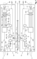
- a binaural hearing system 10 is shown schematically in a block diagram, which comprises a first hearing instrument 1 and a second hearing instrument 2.
- the signal flow from left to right in the hearing instruments is also plotted against a corresponding time scale t.
- the first hearing instrument 1 is provided by a first local hearing aid HG1, which is intended and set up to treat or at least partially correct a hearing impairment of a wearer (not shown in detail), while the second hearing instrument 2 is provided by a second local hearing aid HG2 with comparable properties.
- the first local hearing aid HG1 is designed and set up to be worn on one ear (for example the wearer's left ear), while the second local hearing aid HG2 is designed and set up to be worn on the other ear (for example the wearer's right ear).
- the first and second local hearing aids HG1, HG2 can essentially be constructed symmetrically to each other (e.g. as respective BTE or ITE or RIC or CIC devices), and otherwise have identical electronics (in particular identical signal processors).
- the first hearing instrument 1 has an acousto-electrical first input transducer M1, which in this case is provided by a microphone and which is designed to generate a first input signal E1 from an ambient sound 11.
- the second hearing instrument 2 has an acousto-electrical second input transducer M2, which is also provided by a microphone and is designed to generate a second input signal E2 from the ambient sound 11.
- Preprocessing which can in particular include pre-amplification and digitization, should already take place in the respective input transducers M1, M2, so that the input signals E1, E2 can in particular be provided by digital audio signals.
- the first input signal E1 is split in a first signal processing device DSP1 into a first main signal path HP1 and a first secondary signal path NP1, wherein in the first main signal path HP1 the signal components of the first input signal E1 undergo further processing to form a first output signal A1, which is yet to be described.
- the first output signal A1 is converted into a first output sound signal AS1 by an electro-acoustic first output transducer L1, which in the present case is provided by a loudspeaker (but in alternative embodiments not shown can also be provided by a bone conduction receiver or similar), wherein the voltage fluctuations of the output signal A1 are converted into corresponding air pressure oscillations in the first output sound signal AS1.
- the second input signal E2 is split in a second signal processing device DSP2 into a second main signal path HP2 and a second secondary signal path NP2, whereby in the second main signal path HP1 the signal components of the second input signal E2 are further processed to form a second output signal A2.
- Said second output signal A2 is processed by an electro-acoustic second output transducer L2, which is also provided by a loudspeaker, into a second output sound signal AS2.
- the first input signal E1 is broken down into a first plurality N1 of frequency bands FBa-FBz by means of a first analysis filter bank FA1.
- a first latency T1 arises for signal components SGa-SGz of the first input signal E1 generated in the respective frequency bands FBa-FBz.
- the second input signal E2 is broken down into a plurality of frequency bands by means of a second analysis filter bank FA2, which in this case corresponds to the first plurality N1.
- the first input signal E1 is subjected to a first low-latency analysis 12.
- the first input signal E1 is divided into a second plurality N2 of frequency bands at a first secondary analysis filter bank FAs1, the second plurality N2 being smaller than the first plurality N1 of the frequency bands FBa-FBz of the first analysis filter bank FA1, i.e. N2 ⁇ N1.
- a second latency T2 arising in the first low-latency analysis 12 in the processing of the first input signal E1 is smaller than the said first latency T1 of the first analysis filter bank FA1, i.e. T2 ⁇ T1.
- a first parameter P1 of a signal processing of the first input signal E1 is determined based on respective signal components of the first input signal E1 broken down into the N2 frequency bands.
- the first parameter P1 is determined in such a way that it is to be applied to a number of signal components SGa-SGz of the first input signal E1 in the respective frequency bands FBa-FBz.
- the first parameter P1 can in particular be given by an amplification factor, a compression ratio and/or a characteristic curve and/or a time constant ("attack" or "release”) of a compression.
- the second input signal E2 is subjected to a second low-latency analysis 13 in the second secondary signal path NP2.
- the second input signal E2 is passed through a second secondary analysis filter bank FAs2 is divided into a plurality of frequency bands, which in the present case corresponds to the second plurality N2.
- the number of frequency bands of the second secondary analysis filter bank FAs2 is preferably less than the number of frequency bands of the second analysis filter bank FA2.
- a second parameter P2 of a signal processing of the second input signal E2 is determined based on respective signal components of the second input signal E2 broken down into frequency bands by the second secondary analysis filter bank FAs2.
- the second parameter P2 preferably indicates the same electronic or physical quantity as the first parameter P1 (i.e. is preferably also given by a gain factor or one of the compression quantities mentioned), and differs from the first parameter at most in the numerical value.
- the second parameter P2 allows a conclusion to be drawn about an electronic or physical quantity equivalent to the first parameter P1 (for example as a signal level or a level peak, based on which a conclusion about a compression parameter is possible).
- the first parameter P1 is now transmitted immediately after its generation from the first hearing instrument 1 to the second hearing instrument 2 and received there. This is preferably done using appropriate communication devices K1, K2 in both hearing instruments 1, 2 (e.g. via Bluetooth or NFC-enabled antennas or similar). Conversely, the second parameter P2 is simultaneously transmitted from the second hearing instrument 2 to the first hearing instrument 1 and received there. Thus, at a point in time that occurs negligibly later after the end of the second latency (i.e. for practical purposes essentially "at the end of the second latency", calculated from a specific reference point in time), the first and second parameters P1, P2 are present locally in both hearing instruments 1, 2.
- the same algorithm 15 is now applied to both parameters P1, P2 together in the respective signal processing device DSP1, DSP2 in order to locally determine to determine the same synchronized parameter Ps.
- the mathematical function Q (P1, P2) can in particular comprise a maximum value formation, a minimum value formation, a (possibly weighted) average value formation and/or a sum formation.
- both hearing instruments 1, 2 there is now locally synchronized parameter Ps (i.e. with the same value).
- the synchronized parameter Ps calculated from a reference time TR (such as a specific sample or the start of a so-called "frame"), is available before the division of a corresponding frame by the first or second analysis filter bank FA1, FA2 is completed.
- the transmission time of the first or second parameter P1, P2 to the second or first hearing instrument 2, 1 and the runtime for the algorithm 15 for determining the synchronized parameter Ps were also taken into account.
- the said transmission time TÜ between the hearing instruments 1, 2 and the running time TL of the algorithm 15 are less than the difference T1 - T2 between the first and the second latency.
- a delay V is applied to the synchronized parameter Ps in the first secondary signal path NP1, ie in order to achieve a
- the delay V is applied in the first secondary signal path NP2 in addition to the second latency T2 to the transmission time TÜ of the second parameter P2 from the second hearing instrument 2 to the first hearing instrument 1 and to the runtime TL of algorithm 15 (which determines the synchronized parameter Ps), so that the synchronized parameter Ps is applied with respect to the reference time TR in the first main signal path HP1 exactly after the first latency T1 has
- a comparable application of the synchronized parameter Ps takes place in the second main signal path HP2 of the second hearing instrument 2 to signal components of the second input signal E2 (with a corresponding delay of the synchronized parameter Ps in the second secondary signal path NP2; not shown).
- the delay V is omitted.
- the number of frequency bands of the second low-latency analysis 13 is preferably selected such that, together with the transmission time TÜ and the propagation time TL, it corresponds to the first latency T1, which results from the number of frequency bands into which the first input signal E1 is divided in the first main signal path HP1.
- the signal components SGa-SGz of the first input signal E1 in the first main signal path HP1 are combined to form the first output signal A1 by a first synthesis filter bank FS1 after the application 16 of the synchronized parameter Ps (which can be given, for example, with an amplification factor as synchronized parameter Ps by a simple multiplication of the signal components SGa-SGz in the relevant frequency bands FBa-FBz).
- the synchronized parameter Ps which can be given, for example, with an amplification factor as synchronized parameter Ps by a simple multiplication of the signal components SGa-SGz in the relevant frequency bands FBa-FBz.
- Any further signal processing steps, whether for the signal components SGa-SGz in the frequency bands FBa-FBz or in the already combined first output signal A1 are possible in Figure 1 However, for reasons of clarity, this is not shown.
- the first output signal A1 converted by the first output transducer L1 into the first output sound signal AS1.
- the signal components of the second input signal E2 in the frequency bands are combined by a second synthesis filter bank FS2 after the application of the synchronized parameter Ps to the respective signal components to form the second output signal A2, which is converted by the second output transducer L2 into the second output sound signal AS2.
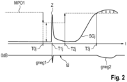
- FIG 2 is a schematic diagram showing a signal level of a signal component SGj of the input signal E1 (in a frequency band FBj) according to Figure 1 and a signal component SGj to be applied in accordance with Figure 1 synchronized signal processing in the form of a signal amplification gj in the frequency band FBj is shown against a time axis t.
- a signal amplification gj in the frequency band FBj is shown against a time axis t.
- a first maximum output level MPO1 is defined (upper horizontal dashed line), which, if exceeded, would lead to compression of the signal component SGj, but is not applied in the absence of a signal level before the point in time T0j.
- a transient is determined in the first secondary signal path NP1 based on a very steep level increase in the time domain, and a switching value for reducing the first maximum output level MPO1 by a predetermined amount DPO to a second maximum output level MPO2 is determined as the first parameter P1.
- the synchronized parameter Ps is determined from the first parameter P1 and the second parameter P2.
- the synchronized parameter Ps in this case then provides for the said reduction of the first maximum output level MPO1 by the specified amount DPO to the second maximum output level MPO2 (switching value 1), if the first or the second parameter P1, P2 provides for this (maximum of the respective switching values) to take into account the fact that a transient is not detected with sufficient precision due to head shading on one side, etc.
- the parameter Ps synchronized in this way reduces the first maximum output level MPO1 by the specified amount DPO to the second maximum output level MPO2 at time T0j (the latency in the transmission is to be neglected here compared to the latency of the first analysis filter bank FA1). Due to the latency of the first analysis filter bank FA1, the transient mentioned only delivers a contribution Z in the frequency band FBj at time T1j, which now exceeds the second maximum output level MPO2 and is correspondingly reduced by applying a first negative gain gneg1.
- the reduction of the maximum output level is canceled at a time T2j, and the first maximum output level MPO1 is now valid again. If, from a time T3j, the level of the signal component SGj continuously exceeds the first maximum output level MPO1, but without a transient occurring, the signal component SGj is reduced accordingly by a second negative gain gneg2.
Landscapes
- Engineering & Computer Science (AREA)
- Health & Medical Sciences (AREA)
- General Health & Medical Sciences (AREA)
- Neurosurgery (AREA)
- Otolaryngology (AREA)
- Physics & Mathematics (AREA)
- Acoustics & Sound (AREA)
- Signal Processing (AREA)
- Computer Networks & Wireless Communication (AREA)
- Circuit For Audible Band Transducer (AREA)
- Stereophonic System (AREA)
Applications Claiming Priority (1)
| Application Number | Priority Date | Filing Date | Title |
|---|---|---|---|
| DE102023200405.4A DE102023200405A1 (de) | 2023-01-19 | 2023-01-19 | Binaurales Hörsystem mit zwei Hörinstrumenten sowie Verfahren zum Betrieb eines solchen Hörsystems |
Publications (1)
| Publication Number | Publication Date |
|---|---|
| EP4404591A1 true EP4404591A1 (fr) | 2024-07-24 |
Family
ID=89620719
Family Applications (1)
| Application Number | Title | Priority Date | Filing Date |
|---|---|---|---|
| EP24152467.7A Pending EP4404591A1 (fr) | 2023-01-19 | 2024-01-17 | Système auditif binaural comportant deux instruments auditifs ainsi que procédé de fonctionnement d'un tel système auditif |
Country Status (4)
| Country | Link |
|---|---|
| US (1) | US20240276161A1 (fr) |
| EP (1) | EP4404591A1 (fr) |
| CN (1) | CN118368573A (fr) |
| DE (1) | DE102023200405A1 (fr) |
Citations (4)
| Publication number | Priority date | Publication date | Assignee | Title |
|---|---|---|---|---|
| US20150124975A1 (en) * | 2013-11-05 | 2015-05-07 | Oticon A/S | Binaural hearing assistance system comprising a database of head related transfer functions |
| EP3337186A1 (fr) * | 2016-12-16 | 2018-06-20 | GN Hearing A/S | Système de dispositif auditif binauriculaire ayant un classificateur d'environnement impulsionnel binauriculaire |
| DE102017201195A1 (de) * | 2017-01-25 | 2018-07-26 | Sivantos Pte. Ltd. | Verfahren zum Betrieb eines binauralen Hörgerätesystems |
| DE202019107201U1 (de) * | 2018-12-21 | 2020-04-22 | Sivantos Pte. Ltd. | Binaurales Hörgerät für eine verbesserte räumliche Hörwahrnehmung |
Family Cites Families (4)
| Publication number | Priority date | Publication date | Assignee | Title |
|---|---|---|---|---|
| CA2424093A1 (fr) * | 2003-03-31 | 2004-09-30 | Dspfactory Ltd. | Methode et dispositif de protection contre les chocs acoustiques |
| WO2018130287A1 (fr) * | 2017-01-12 | 2018-07-19 | Sonova Ag | Dispositif auditif avec commande de choc acoustique et procédé de commande de choc acoustique dans un dispositif auditif |
| DE102021205251B4 (de) * | 2021-05-21 | 2024-08-08 | Sivantos Pte. Ltd. | Verfahren und Vorrichtung zur frequenzselektiven Verarbeitung eines Audiosignals mit geringer Latenz |
| US20250094211A1 (en) * | 2021-07-27 | 2025-03-20 | Sonical Sound Solutions | Fully customizable ear worn devices and associated development platform |
-
2023
- 2023-01-19 DE DE102023200405.4A patent/DE102023200405A1/de active Pending
-
2024
- 2024-01-17 EP EP24152467.7A patent/EP4404591A1/fr active Pending
- 2024-01-18 CN CN202410076923.9A patent/CN118368573A/zh active Pending
- 2024-01-19 US US18/417,317 patent/US20240276161A1/en active Pending
Patent Citations (4)
| Publication number | Priority date | Publication date | Assignee | Title |
|---|---|---|---|---|
| US20150124975A1 (en) * | 2013-11-05 | 2015-05-07 | Oticon A/S | Binaural hearing assistance system comprising a database of head related transfer functions |
| EP3337186A1 (fr) * | 2016-12-16 | 2018-06-20 | GN Hearing A/S | Système de dispositif auditif binauriculaire ayant un classificateur d'environnement impulsionnel binauriculaire |
| DE102017201195A1 (de) * | 2017-01-25 | 2018-07-26 | Sivantos Pte. Ltd. | Verfahren zum Betrieb eines binauralen Hörgerätesystems |
| DE202019107201U1 (de) * | 2018-12-21 | 2020-04-22 | Sivantos Pte. Ltd. | Binaurales Hörgerät für eine verbesserte räumliche Hörwahrnehmung |
Also Published As
| Publication number | Publication date |
|---|---|
| US20240276161A1 (en) | 2024-08-15 |
| DE102023200405A1 (de) | 2024-07-25 |
| CN118368573A (zh) | 2024-07-19 |
Similar Documents
| Publication | Publication Date | Title |
|---|---|---|
| EP3451705B1 (fr) | Procédé et dispositif de reconnaissance rapide de voix propre | |
| EP2180726B2 (fr) | Localisation du son avec des prothèses auditives binauriculaires | |
| EP2506603B1 (fr) | Système d'aide auditive avec système de microphone directif et procédé de fonctionnement dudit système d'aide auditive avec système de microphone directif | |
| EP2164283B1 (fr) | Appareil auditif et fonctionnement d'un appareil auditif doté d'une transposition de fréquence | |
| EP3104627B1 (fr) | Procédé d'amélioration d'un signal d'enregistrement dans un système auditif | |
| EP3461147B1 (fr) | Procédé de fonctionnement d'un appareil auditif | |
| DE102008021613A1 (de) | Verfahren und Vorrichtung zur Bestimmung eines Verschlussgrads bei Hörgeräten | |
| EP3926982B1 (fr) | Procédé de réduction directionnelle du bruit pour un système auditif comprenant un dispositif auditif | |
| EP2437258A2 (fr) | Procédé et dispositif de compression de fréquence à décalage de fréquence sélectif | |
| DE102011006129B4 (de) | Hörvorrichtung mit Rückkopplungsunterdrückungseinrichtung und Verfahren zum Betreiben der Hörvorrichtung | |
| EP2811762B1 (fr) | Système binaural de formation de faisceau fondé sur la logique | |
| EP2822300B1 (fr) | Reconnaissance de situations d'écoute à l'aide de différentes sources de signal | |
| DE102008046040A1 (de) | Verfahren zum Betrieb einer Hörvorrichtung mit Richtwirkung und zugehörige Hörvorrichtung | |
| DE102014218672B3 (de) | Verfahren und Vorrichtung zur Rückkopplungsunterdrückung | |
| EP2373063A1 (fr) | Dispositif auditif et procédé de réglage de celui-ci pour un fonctionnement sans contre-réaction | |
| EP4404591A1 (fr) | Système auditif binaural comportant deux instruments auditifs ainsi que procédé de fonctionnement d'un tel système auditif | |
| DE102010041644B4 (de) | Verfahren zur Frequenzkompression mit harmonischer Korrektur und Vorrichtung | |
| EP4443910A1 (fr) | Procédé de localisation d'une source sonore pour un système auditif binaural | |
| EP2658289A1 (fr) | Procédé de commande dýune caractéristique de guidage et système auditif | |
| EP3364668A1 (fr) | Procédé de fonctionnement d'un dispositif auditif et dispositif auditif | |
| DE102023200581B4 (de) | Verfahren zum Betrieb eines Hörinstruments | |
| DE102007030067B4 (de) | Hörgerät mit passiver, eingangspegelabhängiger Geräuschreduktion und Verfahren | |
| EP4518357A1 (fr) | Procédé de traitement de signal directionnel pour système auditif | |
| EP3048813A1 (fr) | Procédé et dispositif de suppression du bruit basée sur l'inter-corrélation de bandes secondaires | |
| DE102024205358A1 (de) | Verfahren zur Rauschunterdrückung in einem Hörinstrument |
Legal Events
| Date | Code | Title | Description |
|---|---|---|---|
| PUAI | Public reference made under article 153(3) epc to a published international application that has entered the european phase |
Free format text: ORIGINAL CODE: 0009012 |
|
| STAA | Information on the status of an ep patent application or granted ep patent |
Free format text: STATUS: THE APPLICATION HAS BEEN PUBLISHED |
|
| AK | Designated contracting states |
Kind code of ref document: A1 Designated state(s): AL AT BE BG CH CY CZ DE DK EE ES FI FR GB GR HR HU IE IS IT LI LT LU LV MC ME MK MT NL NO PL PT RO RS SE SI SK SM TR |
|
| STAA | Information on the status of an ep patent application or granted ep patent |
Free format text: STATUS: REQUEST FOR EXAMINATION WAS MADE |
|
| 17P | Request for examination filed |
Effective date: 20250114 |