EP4404580A1 - Verfahren und vorrichtung zur steuerung der rundsendung sowie speichermedium und computerprogrammprodukt - Google Patents
Verfahren und vorrichtung zur steuerung der rundsendung sowie speichermedium und computerprogrammprodukt Download PDFInfo
- Publication number
- EP4404580A1 EP4404580A1 EP22897174.3A EP22897174A EP4404580A1 EP 4404580 A1 EP4404580 A1 EP 4404580A1 EP 22897174 A EP22897174 A EP 22897174A EP 4404580 A1 EP4404580 A1 EP 4404580A1
- Authority
- EP
- European Patent Office
- Prior art keywords
- microphone array
- location
- sound
- camera
- microphone
- Prior art date
- Legal status (The legal status is an assumption and is not a legal conclusion. Google has not performed a legal analysis and makes no representation as to the accuracy of the status listed.)
- Pending
Links
Images







Classifications
-
- H—ELECTRICITY
- H04—ELECTRIC COMMUNICATION TECHNIQUE
- H04N—PICTORIAL COMMUNICATION, e.g. TELEVISION
- H04N23/00—Cameras or camera modules comprising electronic image sensors; Control thereof
- H04N23/60—Control of cameras or camera modules
- H04N23/695—Control of camera direction for changing a field of view, e.g. pan, tilt or based on tracking of objects
-
- H—ELECTRICITY
- H04—ELECTRIC COMMUNICATION TECHNIQUE
- H04N—PICTORIAL COMMUNICATION, e.g. TELEVISION
- H04N5/00—Details of television systems
- H04N5/222—Studio circuitry; Studio devices; Studio equipment
- H04N5/262—Studio circuits, e.g. for mixing, switching-over, change of character of image, other special effects ; Cameras specially adapted for the electronic generation of special effects
- H04N5/268—Signal distribution or switching
-
- H—ELECTRICITY
- H04—ELECTRIC COMMUNICATION TECHNIQUE
- H04S—STEREOPHONIC SYSTEMS
- H04S7/00—Indicating arrangements; Control arrangements, e.g. balance control
- H04S7/30—Control circuits for electronic adaptation of the sound field
- H04S7/302—Electronic adaptation of stereophonic sound system to listener position or orientation
-
- G—PHYSICS
- G01—MEASURING; TESTING
- G01S—RADIO DIRECTION-FINDING; RADIO NAVIGATION; DETERMINING DISTANCE OR VELOCITY BY USE OF RADIO WAVES; LOCATING OR PRESENCE-DETECTING BY USE OF THE REFLECTION OR RERADIATION OF RADIO WAVES; ANALOGOUS ARRANGEMENTS USING OTHER WAVES
- G01S3/00—Direction-finders for determining the direction from which infrasonic, sonic, ultrasonic or electromagnetic waves, or particle emission, not having a directional significance, are being received
- G01S3/80—Direction-finders for determining the direction from which infrasonic, sonic, ultrasonic or electromagnetic waves, or particle emission, not having a directional significance, are being received using ultrasonic, sonic or infrasonic waves
- G01S3/802—Systems for determining direction or deviation from predetermined direction
- G01S3/808—Systems for determining direction or deviation from predetermined direction using transducers spaced apart and measuring phase or time difference between signals therefrom, i.e. path-difference systems
- G01S3/8083—Systems for determining direction or deviation from predetermined direction using transducers spaced apart and measuring phase or time difference between signals therefrom, i.e. path-difference systems determining direction of source
-
- G—PHYSICS
- G01—MEASURING; TESTING
- G01S—RADIO DIRECTION-FINDING; RADIO NAVIGATION; DETERMINING DISTANCE OR VELOCITY BY USE OF RADIO WAVES; LOCATING OR PRESENCE-DETECTING BY USE OF THE REFLECTION OR RERADIATION OF RADIO WAVES; ANALOGOUS ARRANGEMENTS USING OTHER WAVES
- G01S5/00—Position-fixing by co-ordinating two or more direction or position line determinations; Position-fixing by co-ordinating two or more distance determinations
- G01S5/16—Position-fixing by co-ordinating two or more direction or position line determinations; Position-fixing by co-ordinating two or more distance determinations using electromagnetic waves other than radio waves
-
- G—PHYSICS
- G01—MEASURING; TESTING
- G01S—RADIO DIRECTION-FINDING; RADIO NAVIGATION; DETERMINING DISTANCE OR VELOCITY BY USE OF RADIO WAVES; LOCATING OR PRESENCE-DETECTING BY USE OF THE REFLECTION OR RERADIATION OF RADIO WAVES; ANALOGOUS ARRANGEMENTS USING OTHER WAVES
- G01S5/00—Position-fixing by co-ordinating two or more direction or position line determinations; Position-fixing by co-ordinating two or more distance determinations
- G01S5/18—Position-fixing by co-ordinating two or more direction or position line determinations; Position-fixing by co-ordinating two or more distance determinations using ultrasonic, sonic or infrasonic waves
-
- G—PHYSICS
- G01—MEASURING; TESTING
- G01S—RADIO DIRECTION-FINDING; RADIO NAVIGATION; DETERMINING DISTANCE OR VELOCITY BY USE OF RADIO WAVES; LOCATING OR PRESENCE-DETECTING BY USE OF THE REFLECTION OR RERADIATION OF RADIO WAVES; ANALOGOUS ARRANGEMENTS USING OTHER WAVES
- G01S5/00—Position-fixing by co-ordinating two or more direction or position line determinations; Position-fixing by co-ordinating two or more distance determinations
- G01S5/18—Position-fixing by co-ordinating two or more direction or position line determinations; Position-fixing by co-ordinating two or more distance determinations using ultrasonic, sonic or infrasonic waves
- G01S5/20—Position of source determined by a plurality of spaced direction-finders
-
- G—PHYSICS
- G01—MEASURING; TESTING
- G01S—RADIO DIRECTION-FINDING; RADIO NAVIGATION; DETERMINING DISTANCE OR VELOCITY BY USE OF RADIO WAVES; LOCATING OR PRESENCE-DETECTING BY USE OF THE REFLECTION OR RERADIATION OF RADIO WAVES; ANALOGOUS ARRANGEMENTS USING OTHER WAVES
- G01S5/00—Position-fixing by co-ordinating two or more direction or position line determinations; Position-fixing by co-ordinating two or more distance determinations
- G01S5/18—Position-fixing by co-ordinating two or more direction or position line determinations; Position-fixing by co-ordinating two or more distance determinations using ultrasonic, sonic or infrasonic waves
- G01S5/22—Position of source determined by co-ordinating a plurality of position lines defined by path-difference measurements
-
- H—ELECTRICITY
- H04—ELECTRIC COMMUNICATION TECHNIQUE
- H04N—PICTORIAL COMMUNICATION, e.g. TELEVISION
- H04N5/00—Details of television systems
- H04N5/222—Studio circuitry; Studio devices; Studio equipment
- H04N5/262—Studio circuits, e.g. for mixing, switching-over, change of character of image, other special effects ; Cameras specially adapted for the electronic generation of special effects
-
- H—ELECTRICITY
- H04—ELECTRIC COMMUNICATION TECHNIQUE
- H04N—PICTORIAL COMMUNICATION, e.g. TELEVISION
- H04N7/00—Television systems
- H04N7/14—Systems for two-way working
- H04N7/15—Conference systems
-
- H—ELECTRICITY
- H04—ELECTRIC COMMUNICATION TECHNIQUE
- H04R—LOUDSPEAKERS, MICROPHONES, GRAMOPHONE PICK-UPS OR LIKE ACOUSTIC ELECTROMECHANICAL TRANSDUCERS; ELECTRIC HEARING AIDS; PUBLIC ADDRESS SYSTEMS
- H04R1/00—Details of transducers, loudspeakers or microphones
- H04R1/20—Arrangements for obtaining desired frequency or directional characteristics
- H04R1/32—Arrangements for obtaining desired frequency or directional characteristics for obtaining desired directional characteristic only
- H04R1/40—Arrangements for obtaining desired frequency or directional characteristics for obtaining desired directional characteristic only by combining a number of identical transducers
-
- H—ELECTRICITY
- H04—ELECTRIC COMMUNICATION TECHNIQUE
- H04R—LOUDSPEAKERS, MICROPHONES, GRAMOPHONE PICK-UPS OR LIKE ACOUSTIC ELECTROMECHANICAL TRANSDUCERS; ELECTRIC HEARING AIDS; PUBLIC ADDRESS SYSTEMS
- H04R1/00—Details of transducers, loudspeakers or microphones
- H04R1/20—Arrangements for obtaining desired frequency or directional characteristics
- H04R1/32—Arrangements for obtaining desired frequency or directional characteristics for obtaining desired directional characteristic only
- H04R1/40—Arrangements for obtaining desired frequency or directional characteristics for obtaining desired directional characteristic only by combining a number of identical transducers
- H04R1/406—Arrangements for obtaining desired frequency or directional characteristics for obtaining desired directional characteristic only by combining a number of identical transducers microphones
-
- H—ELECTRICITY
- H04—ELECTRIC COMMUNICATION TECHNIQUE
- H04R—LOUDSPEAKERS, MICROPHONES, GRAMOPHONE PICK-UPS OR LIKE ACOUSTIC ELECTROMECHANICAL TRANSDUCERS; ELECTRIC HEARING AIDS; PUBLIC ADDRESS SYSTEMS
- H04R3/00—Circuits for transducers
- H04R3/005—Circuits for transducers for combining the signals of two or more microphones
Definitions
- This application relates to the field of communication technologies, and in particular, to a tracking control method and apparatus, a storage medium, and a computer program product.
- Tracking means that a camera is controlled based on a real-time shooting requirement to shoot a key object (a person or an object) in a scene, to output a video image in a video shooting process.
- the camera may be controlled to shoot a current speaker, and when the speaker changes, the camera may be controlled to shoot a new speaker.
- a shooting direction of the camera may be adjusted, or a video image may be selected from video images of a plurality of cameras, or a part of the video image may be captured.
- a control device recognizes a video image that is shot by the camera in real time, determines an object (that is, the foregoing key object) having a specified feature in the image, and controls the camera to shoot the object. For example, in a conference scenario, the control device may recognize a person standing or having a mouth movement (speaking) in a video image shot in real time, determine the person as a speaker, and then control the camera to shoot a close-up of the speaker for playing.
- Embodiments of this application provide a tracking control method, to resolve a problem of poor tracking accuracy in the conventional technology.
- the technical solutions are as follows.
- a tracking control method is provided.
- the method is applied to a tracking control system, and the tracking control system includes a first microphone array, a second microphone array, a camera, and a control device.
- the method includes: The control device determines a location of the first microphone array and a location of the camera; when a sound source object makes a sound, the control device determines a location of the sound source object based on a location of the sound source object relative to the first microphone array, a location of the sound source object relative to the second microphone array, the location of the first microphone array, and a location of the second microphone array; and the control device determines a tracking operation on the camera based on the location of the sound source object and the location of the camera.
- each microphone in the first microphone array may detect corresponding audio data, and the first microphone array sends the audio data to the control device.
- the control device may perform sound source localization based on the audio data, and determine an azimuth ⁇ 1 of the speaker relative to the first microphone array.
- An algorithm used in a sound source localization process may be a steered-response power (steered-response power, SRP) algorithm or the like.
- the control device may also perform sound source localization based on audio data detected by a microphone in the second microphone array, and determine an azimuth ⁇ 2 of the speaker relative to the second microphone array.
- the control device may obtain a location of the speaker through calculation based on the azimuth ⁇ 1 , the azimuth ⁇ 2 , the location of the first microphone array, the location of the second microphone array, and a geometric relationship between the first microphone array, the second microphone array, and the speaker.
- the control device may obtain the location of the speaker through calculation based on the deviation angle ⁇ 1 of the first microphone array, the deviation angle ⁇ 2 of the second microphone array, the azimuth ⁇ 1 , the azimuth ⁇ 2 , the location of the first microphone array, the location of the second microphone array, and the geometric relationship between the first microphone array, the second microphone array, and the speaker.
- the control device may calculate an azimuth of the speaker relative to the camera and a distance between the speaker and the camera based on the location of the speaker and the location of the camera.
- the distance is a plane equivalent distance, that is, a projection distance between an equivalent center of the camera and an equivalent center of the speaker in a plane.
- a tracking rotation angle of the camera may be determined based on the azimuth of the speaker relative to the camera.
- the camera may include a rotatable camera head and a fixed base.
- the camera head may rotate relative to the fixed base, and an initial shooting direction may be specified for the camera head.
- the initial shooting direction may be the same as a reference direction of the camera head.
- the tracking rotation angle may be an angle of a real-time shooting direction of the camera head relative to the initial shooting direction.
- the initial shooting direction may be considered as a 0-degree direction.
- the tracking rotation angle and the azimuth of the speaker relative to the camera may be the same.
- a tracking focal length of the camera may be determined based on the distance.
- the control device may search a prestored first correspondence table, to determine the tracking focal length corresponding to the distance.
- the first correspondence table may record a correspondence between a distance of the speaker relative to the camera and a focal length of the camera.
- the control device may determine the tracking rotation angle and the tracking focal length of the camera based on the location of the speaker and the location of the camera, to control the camera to rotate to the tracking rotation angle and control the camera to perform shooting based on the tracking focal length.
- the control device may determine the tracking rotation angle and the tracking focal length of the camera based on the deviation angle of the camera, the location of the speaker, and the location of the camera, to control a pan-tilt-zoom of the camera to rotate to the tracking rotation angle and control the camera to perform shooting based on the tracking focal length.
- a plurality of camera heads may be added and arranged in different locations, to better shoot a participant.
- the control device may determine, based on the location of the speaker and locations of two cameras, a target camera that is in the two cameras and that is farther away from the speaker, and determine a tracking operation on the target camera based on the location of the speaker and a location of the target camera.
- the control device may control, based on the location of the sound source object and locations of the plurality of cameras, the plurality of cameras to shoot the sound source object, to obtain a plurality of video images. Then, image recognition may be performed on the plurality of obtained video images, and a video image that meets a target condition is selected as a tracking video image. There may be a plurality of target conditions. For example, a video image in which a face angle is closest to the front is selected as a tracking video image. A face angle in the video image may be determined by using a machine learning model for face angle detection.
- the sound source object makes a sound
- the sound source object can be located based on the sound.
- a speaker does not need to have an obvious movement (for example, an obvious mouth movement) when the sound source object is located based on image recognition.
- an obvious movement for example, an obvious mouth movement
- the first microphone array is integrated with a first sound emitter
- the second microphone array includes a first microphone and a second microphone.
- the control device determines a distance D 1 between the first sound emitter and the first microphone and a distance D 2 between the first sound emitter and the second microphone based on time at which the first microphone and the second microphone receive a sound signal from the first sound emitter and time at which the first sound emitter emits the sound signal.
- the control device determines a location of the first microphone array relative to the second microphone array based on a location of the first microphone, a location of the second microphone, the distance D 1 , and the distance D 2 .
- Equivalent centers of the first sound emitter and the first microphone array may be the same. That is, a location of the first sound emitter and the location of the first microphone array may be the same.
- the location of the first microphone array relative to the second microphone array may be a location of the first sound emitter in the first microphone array relative to the second microphone array.
- the location may be determined by using a coordinate system. For example, when an origin of the coordinate system is set at the center of the second microphone array, coordinates of the first microphone array reflect the location of the first microphone array relative to the second microphone array.
- Manner 1 It may be set that the first sound emitter emits a sound signal each time the first sound emitter is powered on, and the control device may obtain power-on time of the first sound emitter as the time at which the first sound emitter emits the sound signal.
- the control device indicates the first sound emitter to emit a sound signal.
- time at which the sound signal is emitted may be recorded, and then the time is sent to the control device.
- the first sound emitter When the control device controls the first sound emitter to emit a sound signal S 1 , the first sound emitter sends, to the control device for recording, a time point t 1 at which the sound signal S 1 is emitted.
- Each microphone in the second microphone array may receive a sound signal, record a time point at which the sound signal is detected, and send the time point to the control device.
- the control device may obtain a time point t 2 at which the first microphone in the second microphone array detects the sound signal S 1 and a time point t 3 at which the second microphone in the second microphone array detects the sound signal S 1 , and then may obtain, through calculation, duration ⁇ T 1 between the time point t 1 and the time point t 2 and duration ⁇ T 2 between the time point t 1 and the time point t 3 . Further, the control device may obtain, through calculation, the distance D 1 between the first microphone and the first sound emitter and the distance D 2 between the second microphone and the first sound emitter based on prestored sound speed data V
- the control device may obtain the location of the first sound emitter through calculation based on the distance D, the distance D 1 , and the distance D 2 , and a geometric relationship between the first microphone, the second microphone, and the first sound emitter.
- the distance D 1 between the first microphone and the first sound emitter and the distance D 2 between the first sound emitter and the second microphone are determined based on time at which the first microphone and the second microphone receive a sound signal from the first sound emitter and time at which the first sound emitter emits the sound signal, and then the location of the first microphone array relative to the second microphone array is determined based on the location of the first microphone, the location of the second microphone, the distance D 1 , and the distance D 2 .
- a device parameter does not need to be manually calibrated, to improve convenience of calibrating the device parameter.
- the tracking control system further includes a second sound emitter and a third sound emitter, and the second sound emitter and the third sound emitter are integrated on a same electronic screen as the second microphone array.
- the control device obtains an azimuth ⁇ 3 of the second sound emitter relative to the first microphone array and an azimuth ⁇ 4 of the third sound emitter relative to the first microphone array that are sent by the first microphone array.
- the control device determines an orientation of the first microphone array based on the azimuth ⁇ 3 , the azimuth ⁇ 4 , a location of the second sound emitter, and a location of the third sound emitter.
- the location of the second sound emitter and the location of the third sound emitter may be preset, and the control device may prestore the location of the second sound emitter and the location of the third sound emitter, and do not need to obtain the locations from the microphone array.
- An orientation of a device is a direction of a reference direction of the device, and may be represented by an included angle between the reference direction of the device and a specified direction (that is, a deviation angle of the device).
- the specified direction may be an X-axis direction or a Y-axis direction.
- each microphone in the first microphone array may detect corresponding audio data, and the first microphone array sends the audio data to the control device.
- the control device may perform sound source localization based on the audio data, and determine the azimuth ⁇ 3 of the second sound emitter relative to the first microphone array.
- the control device may also perform sound source localization based on audio data detected by a microphone in the first microphone array, and determine the azimuth ⁇ 4 of the third sound emitter relative to the first microphone array.
- X m ( k ) represents a fast Fourier transform (fast Fourier transform, FFT) value of a frequency band k of the m th microphone
- s ( ⁇ ) represents a steering vector corresponding to a sound source located at an angle ⁇ in a two-dimensional space plane.
- the steering vector may be calculated in advance based on a layout of microphones in a microphone array and an angle search range (which is set manually, and is an angle range for determining a maximum extreme point subsequently).
- the first microphone is selected as a reference microphone.
- d m cos ⁇ represents a difference between distances from the sound source to the m th microphone and the reference microphone.
- ⁇ belongs to the angle search range, an angle ⁇ corresponding to a maximum extreme point of Y ( ⁇ ) is determined, that is, an azimuth of the sound source object.
- the control device may determine a distance L between the second sound emitter and the third sound emitter based on location coordinates of the second sound emitter and location coordinates of the third sound emitter. Then, the control device may determine a deviation angle ⁇ 5 of the first microphone array through calculation based on the azimuth ⁇ 3 , the azimuth ⁇ 4 , the location of the second sound emitter, the location of the third sound emitter, and a location relationship between the first microphone array, the second sound emitter, and the third sound emitter.
- the camera is integrated with a fourth sound emitter
- the second microphone array includes a first microphone and a second microphone.
- the control device determines a distance D 3 between the first microphone and the fourth sound emitter and a distance D 4 between the second microphone and the fourth sound emitter based on time at which the first microphone and the second microphone receive a sound signal from the fourth sound emitter and time at which the fourth sound emitter emits the sound signal.
- the control device determines a location of the camera relative to the second microphone array based on a location of the first microphone, a location of the second microphone, the distance D 3 , and the distance D 4 .
- Equivalent centers of the fourth sound emitter and the camera may be the same. That is, a location of the fourth sound emitter may be the same as the location of the camera.
- the control device may record a time point t 4 at which the fourth sound emitter emits the sound signal S 4 .
- Each microphone in the second microphone array may detect corresponding audio data, and record a detection time point corresponding to the audio data, that is, a time point at which the audio data is detected.
- the control device may obtain a time point t 5 at which the first microphone in the second microphone array detects the sound signal S 4 and a time point t 6 at which the second microphone in the second microphone array detects the sound signal S 4 , and then may obtain, through calculation, duration ⁇ T 3 between the time point t 4 and the time point t 5 and duration ⁇ T 4 between the time point t 4 and the time point t 6 . Further, the control device may obtain, through calculation, the distance D 3 between the first microphone and the fourth sound emitter and the distance D 4 between the second microphone and the fourth sound emitter based on prestored sound speed data V
- the control device may obtain the location of the fourth sound emitter through calculation based on the distance D, the distance D 3 , and the distance D 4 , and a geometric relationship between the first microphone, the second microphone, and the fourth sound emitter.
- the distance D 3 between the first microphone and the fourth sound emitter and the distance D 4 between the second microphone and the fourth sound emitter are first determined based on time at which the first microphone and the second microphone receive a sound signal from the fourth sound emitter and time at which the fourth sound emitter emits the sound signal, and then the location of the camera relative to the second microphone array is determined based on the location of the first microphone, the location of the second microphone, the distance D 3 , and the distance D 4 . In this way, a device parameter does not need to be manually calibrated, to improve convenience of calibrating the device parameter.
- the first microphone array is integrated with a first sound emitter
- the camera is integrated with a fourth sound emitter and a third microphone array.
- the control device determines an azimuth ⁇ s of the first sound emitter relative to the third microphone array based on data detected by the third microphone array when the first sound emitter emits a sound signal, and determines an azimuth ⁇ 7 of the fourth sound emitter relative to the first microphone array based on data detected by the first microphone array when the fourth sound emitter emits a sound signal.
- the control device determines a deviation angle of the camera based on the azimuth ⁇ 6 , the azimuth ⁇ 7 , and the orientation of the first microphone array.
- the orientation of the first microphone array may be manually measured and stored in the control device, or may be measured by using a parameter calibration process.
- An equivalent center of the third microphone array may be the same as an equivalent center of the camera. That is, a location of the third microphone array may be the same as the location of the camera.
- a deviation angle of the third microphone array may be the same as the deviation angle of the camera.
- An equivalent center of the fourth sound emitter may be the same as the equivalent center of the camera. That is, a location of the fourth sound emitter may be the same as the location of the camera.
- each microphone in the third microphone array may detect corresponding audio data, and the third microphone array sends the audio data to the control device.
- the control device may perform sound source localization based on the audio data, and determine the azimuth ⁇ s of the first sound emitter relative to the third microphone array.
- the control device may also perform sound source localization based on audio data detected by a microphone in the first microphone array, and determine the azimuth ⁇ 7 of the fourth sound emitter relative to the first microphone array.
- a deviation angle ⁇ 8 of the third microphone and the camera may be obtained through calculation based on the azimuth ⁇ 6 , the azimuth ⁇ 7 , the deviation angle ⁇ 5 , and a geometric relationship between the first sound emitter, the third microphone array, and the fourth sound emitter.
- the azimuth ⁇ s of the first sound emitter relative to the third microphone array is first determined based on the data detected by the third microphone array when the first sound emitter emits a sound signal
- the azimuth ⁇ 7 of the fourth sound emitter relative to the first microphone array is determined based on the data detected by the first microphone array when the fourth sound emitter emits a sound signal
- the deviation angle of the camera is determined based on the azimuth ⁇ 6 , the azimuth ⁇ 7 , and the orientation of the first microphone array.
- the first microphone array is integrated with a light emitter
- the camera is integrated with a fourth sound emitter.
- the control device determines a location of a light emitting point in an image shot by the camera, where the image is shot when the light emitter emits light, and determines an azimuth ⁇ 9 of the light emitter relative to the camera based on the location of the light emitting point in the image and a rotation angle of the camera.
- the control device determines an azimuth ⁇ 7 of the fourth sound emitter relative to the first microphone array based on data detected by the first microphone array when the fourth sound emitter emits a sound signal.
- the control device determines an orientation of the camera based on the azimuth ⁇ 9 , the azimuth ⁇ 7 , and the orientation of the first microphone array.
- the orientation of the first microphone array is an angle of a reference direction of the first microphone array relative to a first specified direction, and the first specified direction may be an X-axis positive direction or another specified direction.
- the orientation of the camera is an angle of a reference direction of the camera relative to a second specified direction, and the second specified direction may be a Y-axis positive direction.
- An equivalent center of the light emitter may be the same as an equivalent center of the first microphone array. That is, a location of the light emitter may be the same as the location of the first microphone array.
- An equivalent center of the fourth sound emitter may be the same as the equivalent center of the camera. That is, a location of the fourth sound emitter may be the same as the location of the camera.
- the control device may record a correspondence between a focal length of the camera and a horizontal shooting angle range (or referred to as a horizontal angle of view).
- the correspondence may be reported by the camera to the control device, or may be manually recorded into the control device, or the like.
- the control device may determine a current focal length of the camera. Then, a horizontal shooting angle range ⁇ 4 corresponding to the current focal length is searched in the foregoing correspondence table.
- the controller may obtain an image shot by the camera, and determine, in the image, a distance L 3 between a location of the light emitting point and a longitudinal central axis of the image.
- the control device may record a distance L 4 between a left or right boundary of the image and the longitudinal central axis of the image.
- a real-time shooting direction of the camera head corresponds to the longitudinal central axis of the image.
- An azimuth ⁇ 5 of the light emitter relative to the camera head may be determined based on the horizontal shooting angle ⁇ 4 , the distance L 3 , and the distance L 4 .
- the azimuth ⁇ 5 is an anticlockwise included angle from the real-time shooting direction of the camera head to a line connecting the light emitter and the camera head.
- the control device may further obtain a current rotation angle ⁇ 6 of the camera.
- the azimuth ⁇ 9 of the light emitter relative to the camera may be obtained through calculation based on the azimuth ⁇ 5 and the rotation angle ⁇ 6 .
- the rotation angle ⁇ 6 is a rotation angle of the camera head of the camera relative to the fixed base. Generally, the camera head rotates under control of the control device. Therefore, the control device learns of the rotation angle ⁇ 6 . It should be noted that the rotation angle is not a necessary parameter for calculating the orientation of the camera. In other possible cases, the orientation of the camera may be calculated without using the rotation angle.
- the control device may control the fourth sound emitter to emit a sound signal S 6 .
- each microphone in the first microphone array may detect corresponding audio data, and the first microphone array may send the audio data to the control device.
- the control device may perform sound source localization based on the audio data, and determine the azimuth ⁇ 7 of the fourth sound emitter relative to the first microphone array.
- the control device may obtain a deviation angle ⁇ 8 of the camera through calculation based on the azimuth ⁇ 9 , the azimuth ⁇ 7 , a deviation angle ⁇ 5 of the first microphone array, and a geometric relationship between the first microphone array, the camera, and the fourth sound emitter.
- the location of the light emitting point in the image shot by the camera is first determined, the azimuth ⁇ 9 of the light emitter relative to the camera is determined based on the location of the light emitting point in the image and the rotation angle of the camera, and then the azimuth ⁇ 7 of the fourth sound emitter relative to the first microphone array is determined based on the data detected by the first microphone array when the fourth sound emitter emits a sound signal, and further, the location of the camera is determined based on the azimuth ⁇ 9 , the azimuth ⁇ 7 , and the orientation of the first microphone array.
- a device parameter does not need to be manually calibrated, to improve convenience of calibrating the device parameter.
- the first microphone array is integrated with a first sound emitter
- the second microphone array includes a first microphone and a second microphone.
- the control device determines a distance D 5 between the first sound emitter and the second microphone array and an azimuth ⁇ 10 of the first sound emitter relative to the second microphone array based on data detected by the second microphone array when the first sound emitter emits a sound signal.
- the control device determines the location of the first microphone array based on the distance D 5 , the azimuth ⁇ 10 , and the location of the second microphone array.
- Equivalent centers of the first sound emitter and the first microphone array may be the same. That is, a location of the first sound emitter and the location of the first microphone array may be the same.
- the control device may record a time point t 7 at which the first sound emitter emits the sound signal S 7 .
- a microphone in the second microphone array may detect corresponding audio data, and record a detection time point t 8 corresponding to the audio data, that is, a time point at which the audio data is detected.
- the control device may obtain the time point t 7 at which the second microphone array detects the sound signal S 7 and the time point t 8 at which the second microphone array detects the sound signal S 7 , and then may obtain, through calculation, duration ⁇ T 5 between the time point t 7 and the time point t 8 . Further, the control device may obtain, through calculation, the distance D 5 between the second microphone array and the first sound emitter based on prestored sound speed data V
- the second microphone array may send the audio data corresponding to the sound signal S 7 to the control device.
- the control device may perform sound source localization based on the audio data, and determine the azimuth ⁇ 10 of the first sound emitter relative to the second microphone array.
- the control device may obtain the location of the first sound emitter through calculation based on the distance D 5 , the azimuth ⁇ 10 , the location of the second microphone array, and a geometric relationship between the first sound emitter and the second microphone array.
- the distance D 5 between the first sound emitter and the second microphone array and the azimuth ⁇ 10 of the first sound emitter relative to the second microphone array are first determined based on the data detected by the second microphone array when the first sound emitter emits a sound signal, and then the location of the first microphone array is determined based on the distance D 5 , the azimuth ⁇ 10 , and the location of the second microphone array.
- a device parameter does not need to be manually calibrated, to improve convenience of calibrating the device parameter.
- the first microphone array is integrated with a first sound emitter
- the second microphone array is integrated with a fifth sound emitter.
- the control device determines an azimuth ⁇ 10 of the first sound emitter relative to the second microphone array based on data detected by the second microphone array when the first sound emitter emits a sound signal, and determines an azimuth ⁇ 11 of the fifth sound emitter relative to the first microphone array based on data detected by the first microphone array when the fifth sound emitter emits a sound signal.
- the control device determines an orientation of the first microphone array based on the azimuth ⁇ 10 , the azimuth ⁇ 11 , and an orientation of the second microphone array.
- a microphone in the second microphone array may detect corresponding audio data, and the second microphone array may send the audio data to the control device.
- the control device may perform sound source localization based on the audio data, and determine the azimuth ⁇ 10 of the first sound emitter relative to the second microphone array.
- the control device may also perform sound source localization based on audio data detected by a microphone in the first microphone array, and determine the azimuth ⁇ 11 of the fifth sound emitter relative to the first microphone array.
- the control device may determine a deviation angle ⁇ s of the first microphone array based on the azimuth ⁇ 10 , the azimuth ⁇ 11 , and a geometric relationship between the second microphone array and the first microphone array.
- the control device may determine the deviation angle ⁇ s of the first microphone array based on the azimuth ⁇ 10 , the azimuth ⁇ 11 , the included angle ⁇ 12 , and the geometric relationship between the second microphone array and the first microphone array.
- the deviation angle of the first microphone array may be obtained through a geometric operation based on the foregoing related data.
- the azimuth ⁇ 10 of the first sound emitter relative to the second microphone array is first determined based on the data detected by the second microphone array when the first sound emitter emits a sound signal, and the azimuth ⁇ 11 of the fifth sound emitter relative to the first microphone array is determined based on the data detected by the first microphone array when the fifth sound emitter emits a sound signal. Then, the device determines the orientation of the first microphone array based on the azimuth ⁇ 10 , the azimuth ⁇ 11 , and the orientation of the second microphone array. In this way, a device parameter does not need to be manually calibrated, to improve convenience of calibrating the device parameter.
- the camera is integrated with a fourth sound emitter.
- the control device determines a distance D 6 between the first microphone array and the fourth sound emitter and a distance D 7 between the second microphone array and the fourth sound emitter based on time at which the first microphone array and the second microphone array receive a sound signal from the fourth sound emitter and time at which the fourth sound emitter emits the sound signal.
- the control device determines the location of the camera based on the location of the first microphone array, the location of the second microphone array, the distance D 6 , and the distance D 7 .
- Equivalent centers of the fourth sound emitter and the camera may be the same. That is, a location of the fourth sound emitter may be the same as the location of the camera.
- the control device may record a time point t 9 at which the fourth sound emitter emits the sound signal S 9 .
- the first microphone array and the second microphone array may detect corresponding audio data, and record a detection time point corresponding to the audio data, that is, a time point at which the audio data is detected.
- the control device may obtain a time point t 10 at which the first microphone array detects the sound signal S 9 and a time point t 11 at which the second microphone array detects the sound signal S 9 , and then may obtain, through calculation, duration ⁇ T 6 between the time point t 9 and the time point t 10 and duration ⁇ T 7 between the time point t 9 and the time point tn. Further, the control device may obtain, through calculation, the distance D 6 between the first microphone array and the fourth sound emitter and the distance D 7 between the second microphone array and the fourth sound emitter based on prestored sound speed data V
- the control device may obtain the location of the fourth sound emitter through calculation based on the distance D 6 , the distance D 7 , and the distance D 8 , and a geometric relationship between the first microphone array, the second microphone array, and the fourth sound emitter.
- the distance D 6 between the first microphone array and the fourth sound emitter and the distance D 7 between the second microphone array and the fourth sound emitter are first determined based on time at which the first microphone array and the second microphone array receive a sound signal from the fourth sound emitter and time at which the fourth sound emitter emits the sound signal, and then the location of the camera is determined based on the location of the first microphone array, the location of the second microphone array, the distance D 6 , and the distance D 7 . In this way, a device parameter does not need to be manually calibrated, to improve convenience of calibrating the device parameter.
- control device determines an azimuth of the sound source object relative to the camera and a distance between the sound source object and the camera based on the location of the sound source object and the location of the camera.
- the control device determines a tracking rotation angle of the camera based on the azimuth of the sound source object relative to the camera, and determines a tracking focal length of the camera based on the distance between the sound source object and the camera.
- An azimuth of a speaker relative to the camera and a distance between the speaker and the camera may be calculated based on a location of the speaker and the location of the camera.
- the distance is a plane equivalent distance, that is, a projection distance between an equivalent center of the camera and an equivalent center of the speaker in a plane.
- the tracking rotation angle of the camera may be determined based on the azimuth of the speaker relative to the camera.
- the camera may include a rotatable camera head and a fixed base.
- the camera head may rotate relative to the fixed base, and an initial shooting direction may be specified for the camera head.
- the initial shooting direction may be the same as a reference direction of the camera head.
- the tracking rotation angle may be an angle of a real-time shooting direction of the camera head relative to the initial shooting direction.
- the initial shooting direction may be considered as a 0-degree direction.
- the tracking rotation angle and the azimuth of the speaker relative to the camera may be the same.
- the tracking focal length of the camera may be determined based on the distance.
- the control device may search a prestored first correspondence table, to determine the tracking focal length corresponding to the distance.
- the first correspondence table may record a correspondence between a distance of the speaker relative to the camera and a focal length of the camera.
- the control device based on the location of the sound source object and the location of the camera, the control device first determines the azimuth of the sound source object relative to the camera and the distance between the sound source object and the camera based on the location of the sound source object and the location of the camera, then determines the tracking rotation angle of the camera based on the azimuth of the sound source object relative to the camera, and determines the tracking focal length of the camera based on the distance between the sound source object and the camera. In this way, a tracking parameter does not need to be manually determined, to improve convenience of a tracking process.
- time at which the first sound emitter emits a sound signal is time at which the first sound emitter is powered on.
- the tracking control system further includes another camera.
- the control device determines, based on the location of the sound source object and locations of the two cameras, a target camera that is in the two cameras and that is farther away from the sound source object, and determines a tracking operation on the target camera based on the location of the sound source object and the location of the target camera.
- This processing manner is applicable to the following scenario: A long table is arranged in a conference room, several chairs are arranged on both sides of the long table, and a speaker sits on the chair facing the long table. Cameras are disposed on walls on both sides of the long table. In this scenario, for the two cameras that are disposed on the walls on both sides of the long table, the camera farther away from the speaker can better capture the face of the speaker.
- the target camera that is in the two cameras and that is farther away from the sound source object is determined based on the location of the sound source object and the locations of the two cameras, and a tracking operation on the target camera is determined based on the location of the sound source object and the location of the target camera.
- a tracking control apparatus includes one or more modules, and the one or more modules are configured to implement the method in the first aspect and the possible implementations of the first aspect.
- a computer device includes a memory and a processor.
- the memory is configured to store computer instructions.
- the processor executes the computer instructions stored in the memory, so that the computer device performs the method in the first aspect and the possible implementations of the first aspect.
- a computer-readable storage medium stores computer program code, and when the computer program code is executed by a computer device, the computer device performs the method in the first aspect and the possible implementations of the first aspect.
- a computer program product includes computer program code, and when the computer program code is executed by a computer device, the computer device performs the method in the first aspect and the possible implementations of the first aspect.
- the sound source object makes a sound
- the sound source object can be located based on the sound.
- a speaker does not need to have an obvious movement (for example, an obvious mouth movement) when the sound source object is located based on image recognition.
- an obvious movement for example, an obvious mouth movement
- All devices in a tracking control system may be directional devices.
- the directional device has a reference direction, which may also be referred to as a positive direction of the device.
- the reference direction of the device rotates with rotation of the device.
- the reference direction is generally set manually in a device production process, and a corresponding icon may be set on the device for marking, to facilitate installation by a user.
- a reference direction of a pan-tilt-zoom camera is a direction of any specified radius of a pan-tilt-zoom base, and a line mark may be printed at a location of the radius on the pan-tilt-zoom base.
- a characteristic of the directional device is that a real-time output parameter of the device includes an azimuth or a rotation angle (which is separately described below), and all such angle parameters need to be determined by using the reference direction as a reference.
- An azimuth indicates an azimuth of an object B relative to a device A, and is an included angle from a reference direction of the device A to a line connecting an equivalent center of the object B and an equivalent center of the device A in a plane.
- an anticlockwise included angle from the reference direction of the device A to the line connecting the equivalent center of the object B and the equivalent center of the device A in the plane is defined as the azimuth of the device B relative to the device A.
- a deviation angle is an included angle between a reference direction of a device and a specified direction (which may be manually set).
- a specified direction which may be manually set.
- an anticlockwise included angle from the reference direction of the device to the specified direction is defined as a deviation angle of the device in a plane.
- An orientation of a device is a direction of a reference direction of the device, and may be represented by an included angle (that is, a deviation angle of the device) between the reference direction of the device and a specified direction.
- the specified direction may be an X-axis direction or a Y-axis direction.
- a specified direction is a direction that is set for determining a deviation angle of a device.
- different specified directions may be set for different devices, or a same specified direction may be set for different devices.
- the specified direction is a direction with a coordinate axis as a reference.
- the deviation angle of the device uses the specified direction as a reference.
- the deviation angle of the device also uses the coordinate axis as a reference.
- a reference direction of a microphone array is used as a reference for an orientation of a sound source object.
- the orientation of the sound source object may also be finally represented as an angle relative to the coordinate axis.
- the specified direction is usually set to a positive direction of a coordinate axis.
- a device C may include a component M and a component N.
- the component M is rotatably installed on the component N.
- a rotation angle of the component M is a rotation angle of a positive direction of the component M relative to a positive direction of the component N.
- the positive direction of the component N may be considered as a reference direction of the device C.
- a sound source object is a person or object that makes a sound, and is usually a current speaker.
- a shooting angle range is also referred to as an angle of view, and is a horizontal angle and a vertical angle at which a camera can currently shoot.
- a longitudinal central axis of an image is an imaginary line that can evenly divide the image into two in a vertical direction of the image.
- the sound emitter in embodiments of this application is a component that can emit a sound under control of a control device.
- the following sound emitter may be an ultrasonic sound emitter, and the emitted sound is an ultrasonic wave.
- Embodiments of this application provide a tracking control method, and the method may be applied to a tracking control system.
- the tracking control system may include a microphone array, a camera, a control device, and the like.
- There may be a plurality of types of microphone arrays for example, a distributed microphone array ("distributed" means that the microphone array is not integrated on another device) or a microphone array integrated on another device.
- the control device may be an independent control device, or may be a control device integrated with a microphone array and/or a camera.
- the tracking control system may further include a device such as a terminal device (for example, a smart screen or a projector).
- the tracking control system may be used for shooting and tracking in a plurality of scenarios, for example, a conference scenario, a teaching scenario, or a program recording scenario. This embodiment is described by using a conference scenario as an example. Other cases are similar to this, and details are not described herein again.
- a very common conference scenario is a long-table conference scenario.
- a long conference table and several seats may be disposed, and the seats are arranged around the long conference table.
- participants may sit on the seats for conferences.
- this conference scenario is used as an example for solution description.
- the tracking control system may include a first microphone array, a second microphone array, a control device, a camera, and the like.
- the first microphone array and the second microphone array may be distributed microphone arrays.
- a distributed microphone array can be placed in any location in the conference scenario.
- the control device may be an independent device, or may be integrated into a microphone array or the camera.
- a plane coordinate system may be set.
- the plane coordinate system may be a two-dimensional rectangular coordinate system in a horizontal plane. Any point in conference room space may be set as an origin of the plane coordinate system.
- An X-axis direction and a Y-axis direction of the plane coordinate system may be any two directions perpendicular to each other in the horizontal plane.
- the control device may record locations, specified directions, and deviation angles of some or all devices such as a microphone array and the camera.
- a location of a device may be coordinates of a projection point of an equivalent center of the device in the plane coordinate system.
- an equivalent center of a device that does not move randomly in a location in a conference room is used as an origin of the coordinate system, and directions that use the device as a reference are an X-axis direction and a Y-axis direction.
- an equivalent center of a conference terminal is used as the origin of the coordinate system
- a normal direction of a screen of the conference terminal is used as the Y-axis direction
- a direction that is in the horizontal plane and that is perpendicular to the normal direction is used as the X-axis direction.
- an embodiment of this application provides a tracking control method.
- the method may be performed by the control device in the tracking control system.
- the control device may be a server, a terminal, a component integrated in another device, or the like.
- the server can be a single server or a server group.
- the terminal may be a device disposed in the conference room, or a device disposed in an enterprise equipment room, or may be a portable device, such as a smart screen, a desktop computer, a notebook computer, a mobile phone, a tablet computer, or a smartwatch.
- the control device may be integrated in a device such as a smart screen, a camera, or a microphone array.
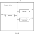
- FIG. 2 is a schematic diagram of a structure of the control device according to an embodiment of this application. From a perspective of hardware composition, a structure of a control device 20 may be shown in FIG. 2 , and includes a processor 201, a memory 202, and a communication component 203.
- the processor 201 may be a central processing unit (central processing unit, CPU), a system on chip (system on chip, SoC), or the like.
- the processor 201 may be configured to determine an azimuth ⁇ 1 of a sound source object relative to the first microphone array and an azimuth ⁇ 2 of the sound source object relative to the second microphone array, and may be further configured to determine a location of the sound source object and the like.
- the memory 202 may include various volatile memories or non-volatile memories, for example, a solid-state disk (solid-state disk, SSD) or a dynamic random access memory (dynamic random access memory, DRAM).
- the memory 202 may be configured to store initial data, intermediate data, and result data that are used in a process in which tracking control is recorded, for example, detection data of the first microphone array, detection data of the second microphone array, the azimuth ⁇ 1 of the sound source object relative to the first microphone array, the azimuth ⁇ 2 of the sound source object relative to the second microphone array, a location of the first microphone array, a location of the second microphone array, and the location of the sound source object.
- the communication component 203 may be a wired network connector, a wireless fidelity (wireless fidelity, Wi-Fi) module, a Bluetooth module, a cellular network communication module, or the like.
- the communication component 203 may be configured to perform data transmission with another device.
- the another device may be a server, a terminal, or the like.
- the control device 20 may receive the detection data of the first microphone array and the detection data of the second microphone array, and may further send the location of the sound source object to a server for storage.
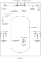
- the tracking control system may include a first microphone array, a second microphone array, and a camera.
- the first microphone array and the second microphone array are distributed microphone arrays. There may be one or more first microphone arrays.
- the camera may be a distributed camera, and there may be one or more cameras.
- the foregoing devices may be disposed in any location.
- the first microphone array and the second microphone array may be disposed on the long table, and two cameras may be suspended on walls on two sides of the long table.
- the control device may record locations and deviation angles of devices such as the first microphone array, the second microphone array, and the cameras.
- a location of a device may be coordinates of a projection point of an equivalent center of the device in a plane coordinate system.
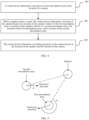
- FIG. 4 The following describes in detail a processing procedure of a tracking control method provided in an embodiment of this application for the tracking control system shown in FIG. 3 .
- the processing procedure may be shown in FIG. 4 .
- FIG. 4 an example in which a sound source object is a speaker in a conference scenario is used for description. Other cases are similar, and details are not described herein again.
- the control device determines a location of the first microphone array and a location of the camera.
- the control device may obtain a prestored location of the first microphone array and a prestored location of the camera.
- the control device may determine the location of the first microphone array and the location of the camera by using a parameter calibration process, and a specific parameter calibration processing process is described in detail in the following.
- the control device determines a location of the speaker based on a location of the speaker relative to the first microphone array, a location of the speaker relative to the second microphone array, the location of the first microphone array, and a location of the second microphone array.
- the location of the speaker relative to the first microphone array and the location of the speaker relative to the second microphone array may be represented by azimuths.
- each microphone in the first microphone array may detect corresponding audio data, and the first microphone array sends the audio data to the control device.
- the control device may perform sound source localization based on the audio data, and determine an azimuth ⁇ 1 of the speaker relative to the first microphone array.
- An algorithm used in a sound source localization process may be a steered-response power (steered-response power, SRP) algorithm or the like.
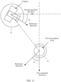
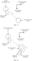
- the control device may also perform sound source localization based on audio data detected by a microphone in the second microphone array, and determine an azimuth ⁇ 2 of the speaker relative to the second microphone array. Refer to FIG. 5 .
- the azimuth ⁇ 1 is an anticlockwise included angle from a reference direction of the first microphone array to a line connecting the speaker and the first microphone array in a horizontal plane
- the azimuth ⁇ 2 is an anticlockwise included angle from a reference direction of the secondmicrophone array to a line connecting the speaker and the second microphone array in the horizontal plane.
- the control device may obtain the location of the speaker through calculation based on the azimuth ⁇ 1 , the azimuth ⁇ 2 , the location of the first microphone array, the location of the second microphone array, and a geometric relationship between the first microphone array, the second microphone array, and the speaker.
- Location coordinates of the speaker are represented as ( x , y ), coordinates of the first microphone array are represented as ( x 1 , y 1 ), and coordinates of the second microphone array are represented as ( x 2 , y 2 ).
- the location coordinates ( x , y ) of the speaker can be obtained through further calculation.
- the control device may obtain the location of the speaker through calculation based on the deviation angle ⁇ 1 of the first microphone array, the deviation angle ⁇ 2 of the second microphone array, the azimuth ⁇ 1 , the azimuth ⁇ 2 , the location of the first microphone array, the location of the second microphone array, and the geometric relationship between the first microphone array, the second microphone array, and the speaker.
- Location coordinates of the speaker are represented as ( x ,y)
- coordinates of the first microphone array are represented as ( x 1 , y 1 )
- coordinates of the second microphone array are represented as ( x 2 ,y 2 ).
- the location coordinates ( x , y ) of the speaker can be obtained through further calculation.
- the foregoing description process is described by using only one of the location relationships as an example.
- the location of the speaker may be obtained through a geometric operation based on the foregoing related data.
- the location relationship and the calculation method used in the foregoing description process do not constitute a limitation on this embodiment.
- the control device determines a tracking operation on the camera based on the location of the speaker and the location of the camera.
- the control device may calculate an azimuth of the speaker relative to the camera and a distance between the speaker and the camera based on the location of the speaker and the location of the camera.
- the distance is a plane equivalent distance, that is, a projection distance between an equivalent center of the camera and an equivalent center of the speaker in a plane.
- a tracking rotation angle of the camera may be determined based on the azimuth of the speaker relative to the camera.
- the camera may include a rotatable camera head and a fixed base.
- the camera head may rotate relative to the fixed base, and an initial shooting direction may be specified for the camera head.
- the initial shooting direction may be the same as a reference direction of the camera head.
- the tracking rotation angle may be an angle of a real-time shooting direction of the camera head relative to the initial shooting direction.
- the initial shooting direction may be considered as a 0-degree direction.
- the tracking rotation angle and the azimuth of the speaker relative to the camera may be the same.
- a tracking focal length of the camera may be determined based on the distance.
- the control device may search a prestored first correspondence table, to determine the tracking focal length corresponding to the distance.
- the first correspondence table may record a correspondence between a distance of the speaker relative to the camera and a focal length of the camera.
- the control device may determine the tracking rotation angle and the tracking focal length of the camera based on the location of the speaker and the location of the camera, to control the camera to rotate to the tracking rotation angle and control the camera to perform shooting based on the tracking focal length.
- the control device may determine the tracking rotation angle and the tracking focal length of the camera based on the deviation angle of the camera, the location of the speaker, and the location of the camera, to control a pan-tilt-zoom of the camera to rotate to the tracking rotation angle and control the camera to perform shooting based on the tracking focal length.
- a plurality of camera heads may be added and arranged in different locations, to better shoot a participant.
- the following describes several different processing manners for a case of a plurality of camera heads:
- the control device may determine, based on the location of the speaker and locations of two cameras, a target camera that is in the two cameras and that is farther away from the speaker, and determine a tracking operation on the target camera based on the location of the speaker and a location of the target camera.
- This processing manner is applicable to the following scenario: A long table is arranged in a conference room, several chairs are arranged on both sides of the long table, and the speaker sits on the chair facing the long table. Cameras are disposed on walls on both sides of the long table. In this scenario, for the two cameras that are disposed on the walls on both sides of the long table, the camera farther away from the speaker can better capture the face of the speaker. Therefore, the camera that is in the two cameras and that is farther away from the speaker may be determined as the target camera, and then the tracking operation on the target camera is determined based on the location of the speaker and the location of the target camera.
- the control device may control, based on the location of the sound source object and locations of the plurality of cameras, the plurality of cameras to shoot the sound source object, to obtain a plurality of video images. Then, image recognition may be performed on the plurality of obtained video images, and a video image that meets a target condition is selected as a tracking video image. There may be a plurality of target conditions. For example, a video image in which a face angle is closest to the front is selected as the tracking video image. A face angle in the video image may be determined by using a machine learning model for face angle detection.
- parameters that may be involved include a location of each device and a deviation angle of each device. All these parameters may be recorded into the control device in advance, and may be measured and recorded after installation. Alternatively, these parameters may be recorded before delivery of the device, and in this case, the factory configuration needs to be considered during installation. Some of these parameters may also be recorded into the control device in advance, and the other parameters may be measured through a parameter calibration process. Specifically, parameters that need to be recorded in advance and parameters that need to be calibrated may be determined based on a device condition in the navigation control system. For example, parameters of a device whose location may change at any time need to be calibrated, for example, a distributed microphone array, and parameters of a device whose location is fixed may be recorded in advance, for example, a microphone array integrated on a conference terminal.
- a person skilled in the art may record a location and a deviation angle of a specified device into the control device in advance, and then the control device determines a location and a deviation angle of another device other than the specified device through a parameter calibration process.
- the specified device may be a microphone array. The following describes the parameter calibration process in detail for the tracking control system in different cases.
- the tracking control system may include a first microphone array, a conference terminal, and a camera.
- the first microphone array is a distributed microphone array, and may be integrated with a first sound emitter.
- the conference terminal may be a smart screen, and the conference terminal may be integrated with a control device, a second microphone array, a second sound emitter, and a third sound emitter.
- the camera may be a distributed camera, and may be integrated with a fourth sound emitter and a third microphone array. There may be one or more cameras. There may be a variety of possibilities for a sound emitter, for example, a common loudspeaker or an ultrasonic sound emitter.
- locations of the foregoing devices may be set randomly.
- the conference terminal is installed on a wall at one end of the long table
- the second microphone array is installed in a middle location at the top of the conference terminal
- the second sound emitter and the third sound emitter are installed on two sides of the conference terminal
- the first microphone array may be disposed on the long table
- two cameras may be suspended on walls at two sides of the long table.
- the control device may prerecord a location of the second microphone array, a deviation angle of the second microphone array, a location of a first microphone in the second microphone array, a location of a second microphone in the second microphone array, a location of the second sound emitter, and a location of the third sound emitter, and prerecord a first specified direction corresponding to the first microphone array and a second specified direction corresponding to the camera.
- the control device establishes a plane rectangular coordinate system in a horizontal plane by using a central location of the second microphone array as an origin of coordinates and using a reference direction of the second microphone array as an X-axis positive direction.
- the reference direction of the second microphone array may be set as a screen direction, and the first microphone and the second microphone in the second microphone array may be symmetrically disposed on the conference terminal relative to the central location.
- a distance between microphones in a microphone array is generally clear.
- location coordinates of the first microphone may be recorded as (0, -D/2), and location coordinates of the second microphone may be recorded as (0, D/2).
- the second sound emitter and the third sound emitter are usually symmetrically disposed on the conference terminal relative to the central location.
- location coordinates of the second sound emitter may be recorded as (0, -L/2), and location coordinates of the third sound emitter may be recorded as (0, L/2).
- the locations of the first microphone, the second microphone, the second sound emitter, and the third sound emitter may be prestored before the conference terminal is delivered from a factory.
- the first specified direction corresponding to the first microphone array may be set and recorded as an X-axis positive direction
- the second specified direction corresponding to the camera may be a Y-axis positive direction.
- the following separately describes a process of calibrating the location of the first microphone array, the deviation angle of the first microphone array, the location of the camera, and the deviation angle of the camera.
- Equivalent centers of the first sound emitter and the first microphone array may be the same. That is, a location of the first sound emitter and the location of the first microphone array may be the same.
- the first sound emitter when the control device controls the first sound emitter to emit the sound signal S 1 , the first sound emitter sends, to the control device for recording, a time point t 1 at which the sound signal S 1 is emitted.
- Each microphone in the second microphone array may receive a sound signal, record a time point at which the sound signal is detected, and send the time point to the control device.
- the control device may obtain a time point t 2 at which the first microphone in the second microphone array detects the sound signal S 1 and a time point t 3 at which the second microphone in the second microphone array detects the sound signal S 1 , and then may obtain, through calculation, duration ⁇ T 1 between the time point t 1 and the time point t 2 and duration ⁇ T 2 between the time point t 1 and the time point t 3 . Further, the control device may obtain, through calculation, the distance D 1 between the first microphone and the first sound emitter and the distance D 2 between the second microphone and the first sound emitter based on prestored sound speed data V
- the control device may obtain the location of the first sound emitter through calculation based on the distance D, the distance D 1 , and the distance D 2 , and a geometric relationship between the first microphone, the second microphone, and the first sound emitter.
- ⁇ 3 An anticlockwise included angle from a line connecting the first microphone and the first sound emitter to a line connecting the first microphone and the second microphone in a horizontal plane is represented as ⁇ 3 , and coordinates of the first sound emitter are represented as ( x 1 , y 1 ).
- the location relationship between the first microphone, the second microphone, and the first sound emitter there are a plurality of possible location relationships between the first microphone, the second microphone, and the first sound emitter.
- the foregoing description process is described by using only one of the location relationships as an example.
- the location of the first sound emitter may be obtained through a geometric operation based on the foregoing related data.
- the location relationship and the calculation method used in the foregoing description process do not constitute a limitation on this embodiment.
- X m ( k ) represents a fast Fourier transform (fast Fourier transform, FFT) value of a frequency band k of the m th microphone
- s ( ⁇ ) represents a steering vector corresponding to a sound source located at an angle ⁇ in a two-dimensional space plane.
- the steering vector may be calculated in advance based on a layout of microphones in a microphone array and an angle search range (which is set manually, and is an angle range for determining a maximum extreme point subsequently).
- the first microphone is selected as a reference microphone.
- d m cos ⁇ represents a difference between distances from the sound source to the m th microphone and the reference microphone.
- an angle ⁇ corresponding to a maximum extreme point of Y ( ⁇ ) is determined, that is, an azimuth of the sound source object.
- the deviation angle of the first microphone array is an included angle of a reference direction of the first microphone array relative to the first specified direction, and the first specified direction may be an X-axis positive direction.
- the control device controls the second sound emitter to emit a sound signal S 2 , and determines an azimuth ⁇ 3 of the second sound emitter relative to the first microphone array based on detection data of the first microphone array.
- the control device controls the third sound emitter to emit a sound signal S 3 , determines an azimuth ⁇ 4 of the third sound emitter relative to the first microphone array based on the detection data of the first microphone array, and determines a deviation angle ⁇ 5 of the first microphone array based on the azimuth ⁇ 3 , the azimuth ⁇ 4 , the location of the second sound emitter, and the location of the third sound emitter.
- each microphone in the first microphone array may detect corresponding audio data, and the first microphone array sends the audio data to the control device.
- the control device may perform sound source localization based on the audio data, and determine the azimuth ⁇ 3 of the second sound emitter relative to the first microphone array.
- the control device may also perform sound source localization based on audio data detected by a microphone in the first microphone array, and determine the azimuth ⁇ 4 of the third sound emitter relative to the first microphone array.
- the control device may determine a distance L between the second sound emitter and the third sound emitter based on location coordinates of the second sound emitter and location coordinates of the third sound emitter.
- the control device may determine the deviation angle ⁇ 5 of the first microphone array through calculation based on the azimuth ⁇ 3 , the azimuth ⁇ 4 , the location of the second sound emitter, the location of the third sound emitter, and a location relationship between the first microphone array, the second sound emitter, and the third sound emitter.
- Coordinates of the first microphone array are represented as ( x 1 , y 1 )
- coordinates of the second sound emitter are represented as (0, -L/2)
- coordinates of the third sound emitter are represented as (0, L/2)
- a distance between the second sound emitter and the first microphone array is represented as L 1
- a distance between the third sound emitter and the first microphone array is represented as L 2 .
- the deviation angle ⁇ 5 may be obtained through further calculation.
- the foregoing description process is described by using only one of the location relationships as an example.
- the deviation angle of the first microphone array may be obtained through a geometric operation based on the foregoing related data.
- the location relationship and the calculation method used in the foregoing description process do not constitute a limitation on this embodiment.
- the control device controls the fourth sound emitter to emit a sound signal S 4 , and determines a distance D 3 between the first microphone and the fourth sound emitter and a distance D 4 between the second microphone and the fourth sound emitter based on a time point at which the fourth sound emitter emits the sound signal S 4 and time points at which the first microphone and the second microphone in the second microphone array detect the sound signal S 4 .
- the control device determines locations of the fourth sound emitter and the camera based on the location of the first microphone, the location of the second microphone, the distance D 3 , and the distance D 4 .
- Equivalent centers of the fourth sound emitter and the camera may be the same. That is, a location of the fourth sound emitter may be the same as the location of the camera.
- the control device may record the time point t 4 at which the fourth sound emitter emits the sound signal S 4 .
- Each microphone in the second microphone array may detect corresponding audio data, and record a detection time point corresponding to the audio data, that is, a time point at which the audio data is detected.
- the control device may obtain a time point t 5 at which the first microphone in the second microphone array detects the sound signal S 4 and a time point t 6 at which the second microphone in the second microphone array detects the sound signal S 4 , and then may obtain, through calculation, duration ⁇ T 3 between the time point t 4 and the time point t 5 and duration ⁇ T 4 between the time point t 4 and the time point t 6 . Further, the control device may obtain, through calculation, the distance D 3 between the first microphone and the fourth sound emitter and the distance D 4 between the second microphone and the fourth sound emitter based on prestored sound speed data V
- the control device may obtain the location of the fourth sound emitter through calculation based on the distance D, the distance D 3 , and the distance D 4 , and a geometric relationship between the first microphone, the second microphone, and the fourth sound emitter.
- a calculation process of determining the location of the fourth sound emitter is similar to the process of determining the location of the first sound emitter in Case 1, and reference may be made to related description of calibration of the location of the first microphone array in Case 1.
- the control device controls the first sound emitter to emit a sound signal S 5 , determines an azimuth ⁇ s of the first sound emitter relative to the third microphone array based on detection data of the third microphone array, controls the fourth sound emitter to emit a sound signal S 6 , and determines an azimuth ⁇ 7 of the fourth sound emitter relative to the first microphone array based on detection data of the first microphone array.
- the control device determines a deviation angle ⁇ 8 of the third microphone array and the camera based on the azimuth ⁇ 6 , the azimuth ⁇ 7 , and the deviation angle ⁇ 5 of the first microphone array.
- each microphone in the third microphone array may detect corresponding audio data, and the third microphone array sends the audio data to the control device.
- the control device may perform sound source localization based on the audio data, and determine the azimuth ⁇ s of the first sound emitter relative to the third microphone array.
- the control device may also perform sound source localization based on audio data detected by a microphone in the first microphone array, and determine the azimuth ⁇ 7 of the fourth sound emitter relative to the first microphone array.
- the deviation angle ⁇ 8 of the third microphone and the camera may be obtained through calculation based on the azimuth ⁇ 6 , the azimuth ⁇ 7 , the deviation angle ⁇ 5 , and a geometric relationship between the first sound emitter, the third microphone array, and the fourth sound emitter. Refer to FIG. 11 .
- the foregoing description process is described by using only one of the location relationships as an example.
- the deviation angles of the third microphone array and the camera may be obtained through a geometric operation based on the foregoing related data.
- the location relationship and the calculation method used in the foregoing description process do not constitute a limitation on this embodiment.
- Case 2 As shown in FIG. 12 , an architecture of a tracking control system is similar to that in Case 1, and a difference lies in that the camera may not be integrated with the third microphone array, and the first microphone array may be integrated with a light emitter in addition to the first sound emitter.
- the light emitter for example, a common LED light source or an infrared LED light source.
- the control device may prerecord a location of the second microphone array, a deviation angle of the second microphone array, a location of a first microphone in the second microphone array, a location of a second microphone in the second microphone array, a location of the second sound emitter, and a location of the third sound emitter, and prerecord a first specified direction corresponding to the first microphone array and a second specified direction corresponding to the camera.
- the control device establishes a plane rectangular coordinate system in a horizontal plane by using a location of the second microphone array as an origin of coordinates and using a reference direction of the second microphone array as an X-axis positive direction.
- the first microphone and the second microphone in the second microphone array may be symmetrically disposed on the conference terminal relative to the central location.
- location coordinates of the first microphone in the second microphone array may be recorded as (0, -D/2), and location coordinates of the second microphone in the second microphone array may be recorded as (0, D/2).
- the second sound emitter and the third sound emitter are usually symmetrically disposed on the conference terminal relative to the central location.
- location coordinates of the second sound emitter may be recorded as (0, -L/2), and location coordinates of the third sound emitter may be recorded as (0, L/2).
- a first specified direction corresponding to the first microphone array may be set and recorded as an X-axis positive direction
- a second specified direction corresponding to the camera may be a Y-axis positive direction.
- the following separately describes a process of calibrating the location of the first microphone array, the deviation angle of the first microphone array, the location of the camera, and the deviation angle of the camera.
- Calibration of the location of the first microphone array, calibration of the deviation angle of the first microphone array, and calibration of the location of the camera in Case 2 are similar to the corresponding processing in Case 1. For details, refer to the description of the corresponding processing in Case 1. Details are not described herein again. Calibration of the deviation angle of the camera in Case 2 is different from that in Case 1. Details are as follows: Calibration of the deviation angle of the camera (if there are a plurality of cameras, a deviation angle of each camera may be calibrated in the following processing manner): The deviation angle of the camera is an angle of a reference direction of the camera relative to the second specified direction, and the second specified direction may be a Y-axis positive direction.
- the control device controls the light emitter to emit light, determines a location of a light emitting point in an image shot by the camera, determines an azimuth ⁇ 9 of the light emitter relative to the camera based on the location of the light emitting point in the image, controls the fourth sound emitter to emit a sound signal S 6 , and determines an azimuth ⁇ 7 of the fourth sound emitter relative to the first microphone array based on detection data of the first microphone array.
- the control device determines a deviation angle ⁇ 8 of the camera based on the azimuth ⁇ 9 , the azimuth ⁇ 7 , and an included angle ⁇ 5 between a reference direction of the first microphone array and the first specified direction.
- An equivalent center of the light emitter may be the same as an equivalent center of the first microphone array. That is, a location of the light emitter may be the same as the location of the first microphone array.
- An equivalent center of the fourth sound emitter may be the same as an equivalent center of the camera. That is, a location of the fourth sound emitter may be the same as the location of the camera.
- the control device may record a correspondence between a focal length of the camera and a horizontal shooting angle range (or referred to as a horizontal angle of view).
- the correspondence may be reported by the camera to the control device, or may be manually recorded into the control device, or the like.
- the control device may determine a current focal length of the camera.
- a horizontal shooting angle range ⁇ 4 corresponding to the current focal length is searched in the foregoing correspondence table.
- the controller may obtain an image shot by the camera, and determine, in the image, a distance L 3 between a location of the light emitting point and a longitudinal central axis of the image.
- the control device may record a distance L 4 between a left or right boundary of the image and the longitudinal central axis of the image.
- a real-time shooting direction of a camera head corresponds to the longitudinal central axis of the image.
- An azimuth ⁇ 5 of the light emitter relative to the camera head may be determined based on the horizontal shooting angle ⁇ 4 , the distance L 3 , and the distance L 4 .
- the azimuth ⁇ 5 is an anticlockwise included angle from the real-time shooting direction of the camera head to a line connecting the light emitter and the camera head. Refer to FIG. 13 and FIG. 14 .
- control device may further obtain a current rotation angle ⁇ 6 of the camera.
- the azimuth ⁇ 9 of the light emitter relative to the camera may be obtained through calculation based on the azimuth ⁇ 5 and the rotation angle ⁇ 6 . Refer to FIG. 14 .
- the rotation angle ⁇ 6 is a rotation angle of the camera head of the camera relative to a fixed base. Generally, the camera head rotates under control of the control device. Therefore, the control device learns of the rotation angle ⁇ 6 .
- the location relationships there are a plurality of possible location relationships between the light emitter, the camera head, and the fixed base.
- only one of the location relationships is used as an example for description.
- the azimuth ⁇ 9 may be obtained through a geometric operation based on the foregoing related data.
- the location relationship and the calculation method used in the foregoing description process do not constitute a limitation on this embodiment.
- the control device may control the fourth sound emitter to emit a sound signal S 6 .
- each microphone in the first microphone array may detect corresponding audio data, and the first microphone array may send the audio data to the control device.
- the control device may perform sound source localization based on the audio data, and determine the azimuth ⁇ 7 of the fourth sound emitter relative to the first microphone array.
- the control device may obtain the deviation angle ⁇ 8 of the camera through calculation based on the azimuth ⁇ 9 , the azimuth ⁇ 7 , the deviation angle ⁇ 5 of the first microphone array, and a geometric relationship between the first microphone array, the camera, and the fourth sound emitter.
- a value of the calculated ⁇ 8 may be adjusted to a range of 0 to 2 ⁇ . For example, if ⁇ 8 is 560°, ⁇ 8 may be adjusted to 200° (that is, 560°-360°).
- the foregoing description process is described by using only one of the location relationships as an example.
- the deviation angle of the camera may be obtained through a geometric operation based on the foregoing related data.
- the location relationship and the calculation method used in the foregoing description process do not constitute a limitation on this embodiment.
- the tracking control system may include a first microphone array, a second microphone array, and a camera. Both the first microphone array and the second microphone array are distributed microphone arrays, the first microphone array may be integrated with a first sound emitter and a light emitter, and the second microphone array may be integrated with a fifth sound emitter. There may be one or more first microphone arrays.
- the camera may be a distributed camera, and may be integrated with a fourth sound emitter. There may be one or more cameras. There may be a variety of possibilities for a sound emitter, for example, a common loudspeaker or an ultrasonic transmitter. There may be a variety of possibilities for the light emitter, for example, a common LED light source or an infrared LED light source.
- the tracking control system may further include a conference terminal, and the control device may be integrated in the conference terminal, or may be integrated in another device, or may be an additional independent terminal device.
- the foregoing devices may be disposed in any location.
- the first microphone array and the second microphone array may be disposed on the long table, and two cameras may be suspended on walls on two sides of the long table.
- the control device may prerecord a location of the second microphone array and a deviation angle of the second microphone array, and prerecord a first specified direction corresponding to the first microphone array and a second specified direction corresponding to the camera.
- the control device establishes a plane rectangular coordinate system in a horizontal plane by using the location of the second microphone array as an origin of coordinates and using a reference direction of the second microphone array as an X-axis positive direction.
- the first specified direction corresponding to the first microphone array may be set and recorded as an X-axis positive direction
- the second specified direction corresponding to the camera may be a Y-axis positive direction.
- Equivalent centers of the first sound emitter and the first microphone array may be the same. That is, a location of the first sound emitter and the location of the first microphone array may be the same.
- the control device may record the time point t 7 at which the first sound emitter emits the sound signal S 7 .
- a microphone in the second microphone array may detect corresponding audio data, and record a detection time point t 8 corresponding to the audio data, that is, a time point at which the audio data is detected.
- the control device may obtain the time point t 7 at which the second microphone array detects the sound signal S 7 and the time point t 8 at which the second microphone array detects the sound signal S 7 , and then may obtain, through calculation, duration ⁇ T 5 between the time point t 7 and the time point t 8 . Further, the control device may obtain, through calculation, the distance D 5 between the second microphone array and the first sound emitter based on prestored sound speed data V
- the second microphone array may send the audio data corresponding to the sound signal S 7 to the control device.
- the control device may perform sound source localization based on the audio data, and determine the azimuth ⁇ 10 of the first sound emitter relative to the second microphone array.
- the control device may obtain the location of the first sound emitter through calculation based on the distance D 5 , the azimuth ⁇ 10 , the location of the second microphone array, and a geometric relationship between the first sound emitter and the second microphone array. Coordinates of the first sound emitter are represented as ( x 1 , y 1 ). Refer to FIG. 17 .
- the location of the first sound emitter may be obtained through a geometric operation based on the foregoing related data.
- the location relationship and the calculation method used in the foregoing description process do not constitute a limitation on this embodiment.
- the control device controls the first sound emitter to emit a sound signal S 7 , determines an azimuth ⁇ 10 of the first sound emitter relative to the second microphone array based on detection data of the second microphone array, controls the fifth sound emitter to emit a sound signal S 8 , and determines an azimuth ⁇ 11 of the fifth sound emitter relative to the first microphone array based on detection data of the first microphone array.
- the control device determines the deviation angle ⁇ 5 of the first microphone array based on the azimuth ⁇ 10 , the azimuth ⁇ 11 , and an included angle ⁇ 12 between the reference direction of the second microphone array and the first specified direction.
- a microphone in the second microphone array may detect corresponding audio data, and the second microphone array may send the audio data to the control device.
- the control device may perform sound source localization based on the audio data, and determine the azimuth ⁇ 10 of the first sound emitter relative to the second microphone array.
- the control device may also perform sound source localization based on audio data detected by a microphone in the first microphone array, and determine the azimuth ⁇ 11 of the fifth sound emitter relative to the first microphone array.
- the control device may determine the deviation angle ⁇ s of the first microphone array based on the azimuth ⁇ 10 , the azimuth ⁇ 11 , and a geometric relationship between the second microphone array and the first microphone array. Refer to FIG. 18 .
- the control device may determine the deviation angle ⁇ 5 of the first microphone array based on the azimuth ⁇ 10 , the azimuth ⁇ 11 , the included angle ⁇ 12 , and the geometric relationship between the second microphone array and the first microphone array. Refer to FIG. 19 .
- the foregoing description process is described by using only one of the location relationships as an example.
- the deviation angle of the first microphone array may be obtained through a geometric operation based on the foregoing related data.
- the location relationship and the calculation method used in the foregoing description process do not constitute a limitation on this embodiment.
- the control device controls the fourth sound emitter to emit a sound signal S 9 , determines a distance D 6 between the first microphone array and the fourth sound emitter and a distance D 7 between the second microphone array and the fourth sound emitter based on a time point at which the fourth sound emitter emits the sound signal S 9 and a time point at which the first microphone array and the second microphone array detect the sound signal S 9 , and determines locations of the fourth sound emitter and the camera based on the location of the first microphone array, the location of the second microphone array, the distance D 6 , and the distance D 7 .
- Equivalent centers of the fourth sound emitter and the camera may be the same. That is, a location of the fourth sound emitter may be the same as the location of the camera.
- the control device may record the time point t 9 at which the fourth sound emitter emits the sound signal S 9 .
- the first microphone array and the second microphone array may detect corresponding audio data, and record a detection time point corresponding to the audio data, that is, a time point at which the audio data is detected.
- the control device may obtain a time point t 10 at which the first microphone array detects the sound signal S 9 and a time point t 11 at which the second microphone array detects the sound signal S 9 , and then may obtain, through calculation, duration ⁇ T 5 between the time point t 9 and the time point t 10 and duration ⁇ T 7 between the time point t 9 and the time point t 11 .
- the control device may obtain the distance D 6 between the first microphone array and the fourth sound emitter and the distance D 7 between the second microphone array and the fourth sound emitter through calculation based on prestored sound speed data V
- the control device may obtain the location of the fourth sound emitter through calculation based on the distance D 6 , the distance D 7 , and the distance D 8 , and a geometric relationship between the first microphone array, the second microphone array, and the fourth sound emitter.
- a calculation process of determining the location of the fourth sound emitter is similar to the process of determining the location of the first sound emitter in Case 1, and reference may be made to related description of calibration of the location of the first microphone array in Case 1.
- embodiments of this application further provide a tracking control apparatus.
- the apparatus may be used in a control device in the tracking control system in the foregoing embodiments.
- the tracking control system includes a first microphone array, a second microphone array, a camera, and a control device. As shown in FIG. 20 , the apparatus includes:
- the first microphone array is integrated with a first sound emitter
- the second microphone array includes a first microphone and a second microphone.
- the calibration module 2001 is configured to: determine a distance D 1 between the first sound emitter and the first microphone and a distance D 2 between the first sound emitter and the second microphone based on time at which the first microphone and the second microphone receive a sound signal from the first sound emitter and time at which the first sound emitter emits the sound signal; and determine a location of the first microphone array relative to the second microphone array based on a location of the first microphone, a location of the second microphone, the distance D 1 , and the distance D 2 .
- the tracking control system further includes a second sound emitter and a third sound emitter, and the second sound emitter and the third sound emitter are integrated on a same electronic screen as the second microphone array.
- the calibration module 2001 is further configured to: obtain an azimuth ⁇ 3 of the second sound emitter relative to the first microphone array and an azimuth ⁇ 4 of the third sound emitter relative to the first microphone array that are sent by the first microphone array; and determine an orientation of the first microphone array based on the azimuth ⁇ 3 , the azimuth ⁇ 4 , a location of the second sound emitter, and a location of the third sound emitter.
- the camera is integrated with a fourth sound emitter
- the second microphone array includes a first microphone and a second microphone.
- the calibration module 2001 is configured to: determine a distance D 3 between the first microphone and the fourth sound emitter and a distance D 4 between the second microphone and the fourth sound emitter based on time at which the first microphone and the second microphone receive a sound signal from the fourth sound emitter and time at which the fourth sound emitter emits the sound signal; and determine a location of the camera relative to the second microphone array based on a location of the first microphone, a location of the second microphone, the distance D 3 , and the distance D 4 .
- the first microphone array is integrated with a first sound emitter
- the camera is integrated with a fourth sound emitter and a third microphone array.
- the calibration module 2001 is configured to: determine an azimuth ⁇ s of the first sound emitter relative to the third microphone array based on data detected by the third microphone array when the first sound emitter emits a sound signal, and determine an azimuth ⁇ 7 of the fourth sound emitter relative to the first microphone array based on data detected by the first microphone array when the fourth sound emitter emits a sound signal; and determine a deviation angle of the camera based on the azimuth ⁇ 6 , the azimuth ⁇ 7 , and the orientation of the first microphone array.
- the first microphone array is integrated with a light emitter
- the camera is integrated with a fourth sound emitter.
- the calibration module 2001 is configured to: determine a location of a light emitting point in an image shot by the camera, where the image is shot when the light emitter emits light; determine an azimuth ⁇ 9 of the light emitter relative to the camera based on the location of the light emitting point in the image and a rotation angle of the camera; determine an azimuth ⁇ 7 of the fourth sound emitter relative to the first microphone array based on data detected by the first microphone array when the fourth sound emitter emits a sound signal; and determine an orientation of the camera based on the azimuth ⁇ 9 , the azimuth ⁇ 7 , and the orientation of the first microphone array.
- the first microphone array is integrated with a first sound emitter
- the second microphone array includes a first microphone and a second microphone.
- the calibration module 2001 is configured to: determine a distance D 5 between the first sound emitter and the second microphone array and an azimuth ⁇ 10 of the first sound emitter relative to the second microphone array based on data detected by the second microphone array when the first sound emitter emits a sound signal; and determine the location of the first microphone array based on the distance D 5 , the azimuth ⁇ 10 , and the location of the second microphone array.
- the first microphone array is integrated with a first sound emitter
- the second microphone array is integrated with a fifth sound emitter.
- the calibration module 2001 is configured to: determine an azimuth ⁇ 10 of the first sound emitter relative to the second microphone array based on data detected by the second microphone array when the first sound emitter emits a sound signal, and determine an azimuth ⁇ 11 of the fifth sound emitter relative to the first microphone array based on data detected by the first microphone array when the fifth sound emitter emits a sound signal; and determine an orientation of the first microphone array based on the azimuth ⁇ 10 , the azimuth ⁇ 11 , and an orientation of the second microphone array.
- the camera is integrated with a fourth sound emitter.
- the calibration module 2001 is further configured to: determine a distance D 6 between the first microphone array and the fourth sound emitter and a distance D 7 between the second microphone array and the fourth sound emitter based on time at which the first microphone array and the second microphone array receive a sound signal from the fourth sound emitter and time at which the fourth sound emitter emits the sound signal; and determine the location of the camera based on the location of the first microphone array, the location of the second microphone array, the distance D 6 , and the distance D7.
- control module 2003 is configured to: determine an azimuth of the sound source object relative to the camera and a distance between the sound source object and the camera based on the location of the sound source object and the location of the camera; and determine a tracking rotation angle of the camera based on the azimuth of the sound source object relative to the camera, and determines a tracking focal length of the camera based on the distance between the sound source object and the camera.
- the tracking control system further includes another camera.
- the control module 2003 is configured to: determine, based on the location of the sound source object and locations of the two cameras, a target camera that is in the two cameras and that is farther away from the sound source object, and determine a tracking operation on the target camera based on the location of the sound source object and the location of the target camera.
- the calibration module 2001, the determining module 2002, and the control module 2003 may be implemented by a processor, or may be implemented by a processor in cooperation with a memory and a transceiver.
- tracking control apparatus when the tracking control apparatus provided in the foregoing embodiment performs the tracking control processing, division into the foregoing functional modules is merely used as an example for description. In actual application, the foregoing functions may be allocated to different functional modules for implementation according to a requirement. That is, an internal structure of the apparatus is divided into different functional modules, to implement all or some of the functions described above.
- the tracking control apparatus provided in the foregoing embodiment and the tracking control method embodiment belong to a same concept. For a specific implementation process, refer to the method embodiment, and details are not described herein again.
- all or a part of the software, hardware, firmware, or any combination thereof may be implemented.
- all or a part of the implementation may be implemented in a form of a computer program product.
- the computer program product includes one or more computer instructions.
- the computer program instructions When the computer program instructions are loaded and executed on a device, all or some of the procedures or functions are generated according to embodiments of this application.
- the computer instructions may be stored in a computer-readable storage medium or may be transmitted from a computer-readable storage medium to another computer-readable storage medium.
- the computer instructions may be transmitted from a website, computer, server, or data center to another website, computer, server, or data center in a wired (for example, a coaxial optical cable, an optical fiber, or a digital subscriber line) or wireless (for example, infrared, radio, or microwave) manner.
- the computer-readable storage medium may be any usable medium accessible by a device, or a data storage device, such as a server or a data center, integrating one or more usable media.
- the usable medium may be a magnetic medium (for example, a floppy disk, a hard disk drive, or a magnetic tape), an optical medium (for example, a digital video disk (digital video disk, DVD)), or a semiconductor medium (for example, a solid-state drive).
- a magnetic medium for example, a floppy disk, a hard disk drive, or a magnetic tape
- an optical medium for example, a digital video disk (digital video disk, DVD)
- a semiconductor medium for example, a solid-state drive
- the program may be stored in a computer-readable storage medium.
- the storage medium may be a read-only memory, a magnetic disk, an optical disc, or the like.
Landscapes
- Engineering & Computer Science (AREA)
- Physics & Mathematics (AREA)
- Signal Processing (AREA)
- Health & Medical Sciences (AREA)
- Otolaryngology (AREA)
- Acoustics & Sound (AREA)
- Remote Sensing (AREA)
- Radar, Positioning & Navigation (AREA)
- General Physics & Mathematics (AREA)
- Multimedia (AREA)
- General Health & Medical Sciences (AREA)
- Electromagnetism (AREA)
- Circuit For Audible Band Transducer (AREA)
- Measurement Of Velocity Or Position Using Acoustic Or Ultrasonic Waves (AREA)
Applications Claiming Priority (3)
| Application Number | Priority Date | Filing Date | Title |
|---|---|---|---|
| CN202111415949 | 2021-11-25 | ||
| CN202210119348.7A CN116193053A (zh) | 2021-11-25 | 2022-02-08 | 导播控制的方法、装置、存储介质和计算机程序产品 |
| PCT/CN2022/105499 WO2023093078A1 (zh) | 2021-11-25 | 2022-07-13 | 导播控制的方法、装置、存储介质和计算机程序产品 |
Publications (2)
| Publication Number | Publication Date |
|---|---|
| EP4404580A1 true EP4404580A1 (de) | 2024-07-24 |
| EP4404580A4 EP4404580A4 (de) | 2025-01-22 |
Family
ID=86446738
Family Applications (1)
| Application Number | Title | Priority Date | Filing Date |
|---|---|---|---|
| EP22897174.3A Pending EP4404580A4 (de) | 2021-11-25 | 2022-07-13 | Verfahren und vorrichtung zur steuerung der rundsendung sowie speichermedium und computerprogrammprodukt |
Country Status (4)
| Country | Link |
|---|---|
| US (1) | US20240314512A1 (de) |
| EP (1) | EP4404580A4 (de) |
| CN (1) | CN116193053A (de) |
| WO (1) | WO2023093078A1 (de) |
Families Citing this family (2)
| Publication number | Priority date | Publication date | Assignee | Title |
|---|---|---|---|---|
| US12587611B2 (en) * | 2023-07-31 | 2026-03-24 | Zoom Communications, Inc. | Controlling follower device video stream capture for video conferencing |
| CN121125971B (zh) * | 2025-09-08 | 2026-03-27 | 广东公信智能会议股份有限公司 | 一种可级联的阵列麦克风基于doa的摄像跟踪方法及系统 |
Family Cites Families (23)
| Publication number | Priority date | Publication date | Assignee | Title |
|---|---|---|---|---|
| US6275258B1 (en) * | 1996-12-17 | 2001-08-14 | Nicholas Chim | Voice responsive image tracking system |
| US6593956B1 (en) * | 1998-05-15 | 2003-07-15 | Polycom, Inc. | Locating an audio source |
| US6980485B2 (en) * | 2001-10-25 | 2005-12-27 | Polycom, Inc. | Automatic camera tracking using beamforming |
| US6912178B2 (en) * | 2002-04-15 | 2005-06-28 | Polycom, Inc. | System and method for computing a location of an acoustic source |
| NO318096B1 (no) * | 2003-05-08 | 2005-01-31 | Tandberg Telecom As | Arrangement og fremgangsmate for lokalisering av lydkilde |
| JP2007214753A (ja) * | 2006-02-08 | 2007-08-23 | Matsushita Electric Ind Co Ltd | 制御方法及び制御装置 |
| US8229134B2 (en) * | 2007-05-24 | 2012-07-24 | University Of Maryland | Audio camera using microphone arrays for real time capture of audio images and method for jointly processing the audio images with video images |
| US8189807B2 (en) * | 2008-06-27 | 2012-05-29 | Microsoft Corporation | Satellite microphone array for video conferencing |
| JP2010206451A (ja) * | 2009-03-03 | 2010-09-16 | Panasonic Corp | カメラ付きスピーカ、信号処理装置、およびavシステム |
| CN101534413B (zh) * | 2009-04-14 | 2012-07-04 | 华为终端有限公司 | 一种远程呈现的系统、装置和方法 |
| JP2012186551A (ja) * | 2011-03-03 | 2012-09-27 | Hitachi Ltd | 制御装置、制御システムと制御方法 |
| US8983089B1 (en) * | 2011-11-28 | 2015-03-17 | Rawles Llc | Sound source localization using multiple microphone arrays |
| US10750132B2 (en) * | 2013-03-14 | 2020-08-18 | Pelco, Inc. | System and method for audio source localization using multiple audio sensors |
| CN104422922A (zh) * | 2013-08-19 | 2015-03-18 | 中兴通讯股份有限公司 | 一种移动终端实现声源定位的方法及装置 |
| CN103439689B (zh) * | 2013-08-21 | 2015-12-23 | 大连理工大学 | 一种分布式麦克风阵列中麦克风位置估计系统 |
| EP3519846B1 (de) * | 2016-09-29 | 2023-03-22 | Dolby Laboratories Licensing Corporation | Automatische entdeckung und lokalisierung von lautsprecherstandorten in raumklangsystemen |
| US9986360B1 (en) * | 2017-06-23 | 2018-05-29 | Cisco Technology, Inc. | Auto-calibration of relative positions of multiple speaker tracking systems |
| CN108802689B (zh) * | 2018-06-14 | 2020-09-01 | 河北工业大学 | 基于声源阵列的空间麦克风定位方法 |
| JP2020036113A (ja) * | 2018-08-28 | 2020-03-05 | シャープ株式会社 | 音響システム |
| WO2021243633A1 (en) * | 2020-06-04 | 2021-12-09 | Plantronics, Inc. | Optimal view selection in a teleconferencing system with cascaded cameras |
| CN113203988B (zh) * | 2021-04-29 | 2023-11-21 | 北京达佳互联信息技术有限公司 | 声源定位方法及装置 |
| WO2023049773A1 (en) * | 2021-09-21 | 2023-03-30 | Shure Acquisition Holdings, Inc. | Conferencing systems and methods for room intelligence |
| EP4548570A1 (de) * | 2022-06-30 | 2025-05-07 | Shure Acquisition Holdings, Inc. | Konferenzsysteme und verfahren zur sprecherverfolgung und kamerapositionierung |
-
2022
- 2022-02-08 CN CN202210119348.7A patent/CN116193053A/zh active Pending
- 2022-07-13 EP EP22897174.3A patent/EP4404580A4/de active Pending
- 2022-07-13 WO PCT/CN2022/105499 patent/WO2023093078A1/zh not_active Ceased
-
2024
- 2024-05-24 US US18/674,769 patent/US20240314512A1/en active Pending
Also Published As
| Publication number | Publication date |
|---|---|
| CN116193053A (zh) | 2023-05-30 |
| WO2023093078A1 (zh) | 2023-06-01 |
| US20240314512A1 (en) | 2024-09-19 |
| EP4404580A4 (de) | 2025-01-22 |
Similar Documents
| Publication | Publication Date | Title |
|---|---|---|
| US20240314512A1 (en) | Tracking control method and apparatus, storage medium, and computer program product | |
| US10812759B2 (en) | Multimodal spatial registration of devices for congruent multimedia communications | |
| US9071895B2 (en) | Satellite microphones for improved speaker detection and zoom | |
| CN103210643A (zh) | 用于使用多个传感器来追踪视频会议中的音频源的方法和装置 | |
| US20180192002A1 (en) | Automated configuration of behavior of a telepresence system based on spatial detection of telepresence components | |
| US9338544B2 (en) | Determination, display, and adjustment of best sound source placement region relative to microphone | |
| US11425502B2 (en) | Detection of microphone orientation and location for directional audio pickup | |
| US20150341719A1 (en) | Precise Tracking of Sound Angle of Arrival at a Microphone Array under Air Temperature Variation | |
| TW201442511A (zh) | 追蹤拍攝系統與方法 | |
| WO2020255766A1 (ja) | 情報処理装置、情報処理方法、プログラム、投映装置、および情報処理システム | |
| US11388537B2 (en) | Configuration of audio reproduction system | |
| CN107124540A (zh) | 采集处理方法、装置及系统 | |
| US20240185876A1 (en) | Sound signal processing method and apparatus, and computer-readable storage medium | |
| CN107295381A (zh) | 可转动设备的调整系统、方法及装置、遥控器 | |
| US20170019585A1 (en) | Camera clustering and tracking system | |
| US20250292437A1 (en) | Conferencing system with intelligent calibration | |
| US10104489B2 (en) | Method for using a mobile device equipped with at least two microphones for determining the direction of loudspeakers in a setup of a surround sound system | |
| US12254634B2 (en) | Panoramic video conference system and method | |
| CN113608167B (zh) | 声源定位方法、装置及设备 | |
| CN111325790A (zh) | 目标追踪方法、设备及系统 | |
| CN116472724B (zh) | 用于远程呈现会议的麦克风阵列的自动校准 | |
| US20250016439A1 (en) | Conferencing systems and methods for adjusting camera tracking based on microphone coverage | |
| Goumopoulos et al. | Bridging the gap between virtual and physical classrooms to enhance distance learning experience | |
| CN120812509A (zh) | 一种无麦克风的声学测算方法、系统、装置及介质 | |
| CN119946215A (zh) | 一种目标对象定位方法、装置、电子设备和存储介质 |
Legal Events
| Date | Code | Title | Description |
|---|---|---|---|
| STAA | Information on the status of an ep patent application or granted ep patent |
Free format text: STATUS: THE INTERNATIONAL PUBLICATION HAS BEEN MADE |
|
| PUAI | Public reference made under article 153(3) epc to a published international application that has entered the european phase |
Free format text: ORIGINAL CODE: 0009012 |
|
| STAA | Information on the status of an ep patent application or granted ep patent |
Free format text: STATUS: REQUEST FOR EXAMINATION WAS MADE |
|
| 17P | Request for examination filed |
Effective date: 20240416 |
|
| AK | Designated contracting states |
Kind code of ref document: A1 Designated state(s): AL AT BE BG CH CY CZ DE DK EE ES FI FR GB GR HR HU IE IS IT LI LT LU LV MC MK MT NL NO PL PT RO RS SE SI SK SM TR |
|
| A4 | Supplementary search report drawn up and despatched |
Effective date: 20250102 |
|
| RIC1 | Information provided on ipc code assigned before grant |
Ipc: H04R 3/00 20060101ALI20241218BHEP Ipc: H04R 1/40 20060101ALI20241218BHEP Ipc: G01S 5/22 20060101ALI20241218BHEP Ipc: G01S 5/20 20060101ALI20241218BHEP Ipc: G01S 5/18 20060101ALI20241218BHEP Ipc: G01S 5/16 20060101ALI20241218BHEP Ipc: G01S 3/808 20060101ALI20241218BHEP Ipc: H04N 7/15 20060101ALI20241218BHEP Ipc: H04N 23/695 20230101AFI20241218BHEP |
|
| DAV | Request for validation of the european patent (deleted) | ||
| DAX | Request for extension of the european patent (deleted) |