EP4404498A2 - Verfahren und vorrichtung zur csi-parameterkonfiguration in drahtlosen kommunikationssystemen - Google Patents
Verfahren und vorrichtung zur csi-parameterkonfiguration in drahtlosen kommunikationssystemen Download PDFInfo
- Publication number
- EP4404498A2 EP4404498A2 EP24181471.4A EP24181471A EP4404498A2 EP 4404498 A2 EP4404498 A2 EP 4404498A2 EP 24181471 A EP24181471 A EP 24181471A EP 4404498 A2 EP4404498 A2 EP 4404498A2
- Authority
- EP
- European Patent Office
- Prior art keywords
- value
- rank
- csi
- parameter
- rrc parameter
- Prior art date
- Legal status (The legal status is an assumption and is not a legal conclusion. Google has not performed a legal analysis and makes no representation as to the accuracy of the status listed.)
- Pending
Links
Images


Classifications
-
- H—ELECTRICITY
- H04—ELECTRIC COMMUNICATION TECHNIQUE
- H04B—TRANSMISSION
- H04B7/00—Radio transmission systems, i.e. using radiation field
- H04B7/02—Diversity systems; Multi-antenna system, i.e. transmission or reception using multiple antennas
- H04B7/04—Diversity systems; Multi-antenna system, i.e. transmission or reception using multiple antennas using two or more spaced independent antennas
- H04B7/0413—MIMO systems
- H04B7/0456—Selection of precoding matrices or codebooks, e.g. using matrices antenna weighting
- H04B7/0482—Adaptive codebooks
-
- H—ELECTRICITY
- H04—ELECTRIC COMMUNICATION TECHNIQUE
- H04B—TRANSMISSION
- H04B7/00—Radio transmission systems, i.e. using radiation field
- H04B7/02—Diversity systems; Multi-antenna system, i.e. transmission or reception using multiple antennas
- H04B7/04—Diversity systems; Multi-antenna system, i.e. transmission or reception using multiple antennas using two or more spaced independent antennas
- H04B7/0413—MIMO systems
- H04B7/0456—Selection of precoding matrices or codebooks, e.g. using matrices antenna weighting
- H04B7/0486—Selection of precoding matrices or codebooks, e.g. using matrices antenna weighting taking channel rank into account
-
- H—ELECTRICITY
- H04—ELECTRIC COMMUNICATION TECHNIQUE
- H04B—TRANSMISSION
- H04B7/00—Radio transmission systems, i.e. using radiation field
- H04B7/02—Diversity systems; Multi-antenna system, i.e. transmission or reception using multiple antennas
- H04B7/04—Diversity systems; Multi-antenna system, i.e. transmission or reception using multiple antennas using two or more spaced independent antennas
- H04B7/06—Diversity systems; Multi-antenna system, i.e. transmission or reception using multiple antennas using two or more spaced independent antennas at the transmitting station
- H04B7/0613—Diversity systems; Multi-antenna system, i.e. transmission or reception using multiple antennas using two or more spaced independent antennas at the transmitting station using simultaneous transmission
- H04B7/0615—Diversity systems; Multi-antenna system, i.e. transmission or reception using multiple antennas using two or more spaced independent antennas at the transmitting station using simultaneous transmission of weighted versions of same signal
- H04B7/0619—Diversity systems; Multi-antenna system, i.e. transmission or reception using multiple antennas using two or more spaced independent antennas at the transmitting station using simultaneous transmission of weighted versions of same signal using feedback from receiving side
- H04B7/0621—Feedback content
- H04B7/0626—Channel coefficients, e.g. channel state information [CSI]
-
- H—ELECTRICITY
- H04—ELECTRIC COMMUNICATION TECHNIQUE
- H04B—TRANSMISSION
- H04B7/00—Radio transmission systems, i.e. using radiation field
- H04B7/02—Diversity systems; Multi-antenna system, i.e. transmission or reception using multiple antennas
- H04B7/04—Diversity systems; Multi-antenna system, i.e. transmission or reception using multiple antennas using two or more spaced independent antennas
- H04B7/06—Diversity systems; Multi-antenna system, i.e. transmission or reception using multiple antennas using two or more spaced independent antennas at the transmitting station
- H04B7/0613—Diversity systems; Multi-antenna system, i.e. transmission or reception using multiple antennas using two or more spaced independent antennas at the transmitting station using simultaneous transmission
- H04B7/0615—Diversity systems; Multi-antenna system, i.e. transmission or reception using multiple antennas using two or more spaced independent antennas at the transmitting station using simultaneous transmission of weighted versions of same signal
- H04B7/0619—Diversity systems; Multi-antenna system, i.e. transmission or reception using multiple antennas using two or more spaced independent antennas at the transmitting station using simultaneous transmission of weighted versions of same signal using feedback from receiving side
- H04B7/0621—Feedback content
- H04B7/063—Parameters other than those covered in groups H04B7/0623 - H04B7/0634, e.g. channel matrix rank or transmit mode selection
-
- H—ELECTRICITY
- H04—ELECTRIC COMMUNICATION TECHNIQUE
- H04B—TRANSMISSION
- H04B7/00—Radio transmission systems, i.e. using radiation field
- H04B7/02—Diversity systems; Multi-antenna system, i.e. transmission or reception using multiple antennas
- H04B7/04—Diversity systems; Multi-antenna system, i.e. transmission or reception using multiple antennas using two or more spaced independent antennas
- H04B7/06—Diversity systems; Multi-antenna system, i.e. transmission or reception using multiple antennas using two or more spaced independent antennas at the transmitting station
- H04B7/0613—Diversity systems; Multi-antenna system, i.e. transmission or reception using multiple antennas using two or more spaced independent antennas at the transmitting station using simultaneous transmission
- H04B7/0615—Diversity systems; Multi-antenna system, i.e. transmission or reception using multiple antennas using two or more spaced independent antennas at the transmitting station using simultaneous transmission of weighted versions of same signal
- H04B7/0619—Diversity systems; Multi-antenna system, i.e. transmission or reception using multiple antennas using two or more spaced independent antennas at the transmitting station using simultaneous transmission of weighted versions of same signal using feedback from receiving side
- H04B7/0621—Feedback content
- H04B7/0634—Antenna weights or vector/matrix coefficients
-
- H—ELECTRICITY
- H04—ELECTRIC COMMUNICATION TECHNIQUE
- H04B—TRANSMISSION
- H04B7/00—Radio transmission systems, i.e. using radiation field
- H04B7/02—Diversity systems; Multi-antenna system, i.e. transmission or reception using multiple antennas
- H04B7/04—Diversity systems; Multi-antenna system, i.e. transmission or reception using multiple antennas using two or more spaced independent antennas
- H04B7/06—Diversity systems; Multi-antenna system, i.e. transmission or reception using multiple antennas using two or more spaced independent antennas at the transmitting station
- H04B7/0613—Diversity systems; Multi-antenna system, i.e. transmission or reception using multiple antennas using two or more spaced independent antennas at the transmitting station using simultaneous transmission
- H04B7/0615—Diversity systems; Multi-antenna system, i.e. transmission or reception using multiple antennas using two or more spaced independent antennas at the transmitting station using simultaneous transmission of weighted versions of same signal
- H04B7/0619—Diversity systems; Multi-antenna system, i.e. transmission or reception using multiple antennas using two or more spaced independent antennas at the transmitting station using simultaneous transmission of weighted versions of same signal using feedback from receiving side
- H04B7/0636—Feedback format
- H04B7/0639—Using selective indices, e.g. of a codebook, e.g. pre-distortion matrix index [PMI] or for beam selection
-
- H—ELECTRICITY
- H04—ELECTRIC COMMUNICATION TECHNIQUE
- H04L—TRANSMISSION OF DIGITAL INFORMATION, e.g. TELEGRAPHIC COMMUNICATION
- H04L5/00—Arrangements affording multiple use of the transmission path
- H04L5/003—Arrangements for allocating sub-channels of the transmission path
- H04L5/0048—Allocation of pilot signals, i.e. of signals known to the receiver
-
- H—ELECTRICITY
- H04—ELECTRIC COMMUNICATION TECHNIQUE
- H04W—WIRELESS COMMUNICATION NETWORKS
- H04W72/00—Local resource management
- H04W72/04—Wireless resource allocation
- H04W72/044—Wireless resource allocation based on the type of the allocated resource
- H04W72/0453—Resources in frequency domain, e.g. a carrier in FDMA
-
- H—ELECTRICITY
- H04—ELECTRIC COMMUNICATION TECHNIQUE
- H04W—WIRELESS COMMUNICATION NETWORKS
- H04W76/00—Connection management
- H04W76/20—Manipulation of established connections
- H04W76/27—Transitions between radio resource control [RRC] states
Definitions
- the present disclosure relates generally to wireless communication systems and more specifically to channel state information (CSI) parameter configuration in wireless communication systems.
- CSI channel state information
- the gNB may transmit a reference signal, e.g., CSI-RS, to the UE for DL channel measurement, and the UE may report (e.g., feedback) information about channel measurement, e.g., CSI, to the gNB.
- CSI-RS reference signal
- the gNB is able to select appropriate communication parameters to efficiently and effectively perform wireless data communication with the UE.
- Embodiments of the present disclosure provide methods and apparatuses to enable channel state information (CSI) reporting in a wireless communication system.
- CSI channel state information
- a UE for CSI reporting in a wireless communication system includes a transceiver configured to receive, from a base station (BS), CSI feedback configuration information including codebook parameters configured jointly via a single radio resource control (RRC) parameter, the codebook parameters comprising L , p , v 0 and ⁇ , wherein the parameter L determines a number of spatial domain (SD) basis vectors, the parameter ⁇ determines a maximum number of coefficients, and the parameters p and v 0 determine a number ( M v ) of frequency domain (FD) basis vectors, wherein the parameter p is for a first rank set and the parameter v 0 is for a second rank set.
- RRC radio resource control
- the UE further includes a processor operably connected to the transceiver, the processor configured to generate the CSI feedback based on the CSI feedback configuration information, wherein the CSI feedback is generated for a rank value v from one of the first and second rank sets.
- the transceiver is further configured to transmit the CSI feedback over an uplink channel.
- a BS in a wireless communication system includes a processor configured to generate CSI feedback configuration information.
- the BS further includes a transceiver operably connected to the processor.
- the transceiver is configured to transmit, to a user equipment (UE), the CSI feedback configuration information including codebook parameters configured jointly via a single radio resource control (RRC) parameter, the codebook parameters comprising L , p , v 0 , and ⁇ , wherein the parameter L determines a number of spatial domain (SD) basis vectors, the parameter ⁇ determines a maximum number of coefficients, and the parameters p and v 0 determine a number ( M v ) of frequency domain (FD) basis vectors, wherein the parameter P is for a first rank set and the parameter v 0 is for a second rank set.
- the transceiver is further configured to receive, from the UE over an uplink channel, a CSI feedback generated for a rank value v from one of the first and second rank sets.
- a method for operating a UE comprises: receiving, from a base station (BS), CSI feedback configuration information including codebook parameters configured jointly via a single radio resource control (RRC) parameter, the codebook parameters comprising L , p , v 0 , and ⁇ , wherein the parameter L determines a number of spatial domain (SD) basis vectors, the parameter ⁇ determines a maximum number of coefficients, and the parameters p and v 0 determine a number ( M v ) of frequency domain (FD) basis vectors, wherein the parameter p is for a first rank set and the parameter v 0 is for a second rank set; generating the CSI feedback based on the CSI feedback configuration information, wherein the CSI feedback is generated for a rank value v from one of the first and second rank sets; and transmitting, to the BS, the CSI feedback over an uplink channel.
- RRC radio resource control
- Couple and its derivatives refer to any direct or indirect communication between two or more elements, whether or not those elements are in physical contact with one another.
- transmit and “communicate,” as well as derivatives thereof, encompass both direct and indirect communication.
- the term “or” is inclusive, meaning and/or.
- controller means any device, system or part thereof that controls at least one operation. Such a controller may be implemented in hardware or a combination of hardware and software and/or firmware. The functionality associated with any particular controller may be centralized or distributed, whether locally or remotely.
- phrases "at least one of,” when used with a list of items, means that different combinations of one or more of the listed items may be used, and only one item in the list may be needed.
- “at least one of: A, B, and C” includes any of the following combinations: A, B, C, A and B, A and C, B and C, and A and B and C.
- various functions described below can be implemented or supported by one or more computer programs, each of which is formed from computer readable program code and embodied in a computer readable medium.
- application and “program” refer to one or more computer programs, software components, sets of instructions, procedures, functions, objects, classes, instances, related data, or a portion thereof adapted for implementation in a suitable computer readable program code.
- computer readable program code includes any type of computer code, including source code, object code, and executable code.
- computer readable medium includes any type of medium capable of being accessed by a computer, such as read only memory (ROM), random access memory (RAM), a hard disk drive, a compact disc (CD), a digital video disc (DVD), or any other type of memory.
- ROM read only memory
- RAM random access memory
- CD compact disc
- DVD digital video disc
- a "non-transitory” computer readable medium excludes wired, wireless, optical, or other communication links that transport transitory electrical or other signals.
- a non-transitory computer readable medium includes media where data can be permanently stored and media where data can be stored and later overwritten, such as a rewritable optical disc or an erasable memory device.
- FIGURES 1 through FIGURE 15 discussed below, and the various embodiments used to describe the principles of the present disclosure in this patent document are by way of illustration only and should not be construed in any way to limit the scope of the disclosure. Those skilled in the art will understand that the principles of the present disclosure may be implemented in any suitably arranged system or device.
- both FDD and TDD are considered as the duplex method for both DL and UL signaling.
- orthogonal frequency division multiplexing OFDM
- orthogonal frequency division multiple access OFDMA
- F-OFDM filtered OFDM
- the 5G or pre-5G communication system is also called a “beyond 4G network" or a "post LTE system.”
- the 5G communication system is considered to be implemented in higher frequency (mmWave) bands, e.g., 60GHz bands, so as to accomplish higher data rates or in lower frequency bands, such as below 6 GHz, to enable robust coverage and mobility support.
- mmWave e.g., 60GHz bands
- MIMO massive multiple-input multiple-output
- FD-MIMO full dimensional MIMO
- array antenna an analog beam forming, large scale antenna techniques and the like are discussed in 5G communication systems.
- RANs cloud radio access networks
- D2D device-to-device
- wireless backhaul communication moving network
- cooperative communication coordinated multi-points (CoMP) transmission and reception, interference mitigation and cancellation and the like.
- CoMP coordinated multi-points
- FQAM frequency shift keying and quadrature amplitude modulation
- SWSC sliding window superposition coding
- AMC adaptive modulation and coding
- FBMC filter bank multi carrier
- NOMA non-orthogonal multiple access
- SCMA sparse code multiple access
- FIGURES 1-4B below describe various embodiments implemented in wireless communications systems and with the use of orthogonal frequency division multiplexing (OFDM) or orthogonal frequency division multiple access (OFDMA) communication techniques.
- OFDM orthogonal frequency division multiplexing
- OFDMA orthogonal frequency division multiple access
- FIGURE 1 illustrates an example wireless network according to embodiments of the present disclosure.
- the embodiment of the wireless network shown in FIGURE 1 is for illustration only. Other embodiments of the wireless network 100 could be used without departing from the scope of this disclosure.
- the wireless network includes a gNB 101, a gNB 102, and a gNB 103.
- the gNB 101 communicates with the gNB 102 and the gNB 103.
- the gNB 101 also communicates with at least one network 130, such as the Internet, a proprietary Internet Protocol (IP) network, or other data network.
- IP Internet Protocol
- the gNB 102 provides wireless broadband access to the network 130 for a first plurality of user equipments (UEs) within a coverage area 120 of the gNB 102.
- the first plurality of UEs includes a UE 111, which may be located in a small business; a UE 112, which may be located in an enterprise (E); a UE 113, which may be located in a WiFi hotspot (HS); a UE 114, which may be located in a first residence (R); a UE 115, which may be located in a second residence (R); and a UE 116, which may be a mobile device (M), such as a cell phone, a wireless laptop, a wireless PDA, or the like.
- M mobile device
- the gNB 103 provides wireless broadband access to the network 130 for a second plurality of UEs within a coverage area 125 of the gNB 103.
- the second plurality of UEs includes the UE 115 and the UE 116.
- one or more of the gNBs 101-103 may communicate with each other and with the UEs 111-116 using 5G, LTE, LTE-A, WiMAX, WiFi, or other wireless communication techniques.
- the term “base station” or “BS” can refer to any component (or collection of components) configured to provide wireless access to a network, such as transmit point (TP), transmit-receive point (TRP), an enhanced base station (eNodeB or eNB), a 5G base station (gNB), a macrocell, a femtocell, a WiFi access point (AP), or other wirelessly enabled devices.
- Base stations may provide wireless access in accordance with one or more wireless communication protocols, e.g., 5G 3GPP new radio interface/access (NR), long term evolution (LTE), LTE advanced (LTE-A), high speed packet access (HSPA), Wi-Fi 802.11a/b/g/n/ac, etc.
- 5G 3GPP new radio interface/access NR
- LTE long term evolution
- LTE-A LTE advanced
- HSPA high speed packet access
- Wi-Fi 802.11a/b/g/n/ac etc.
- the terms “BS” and “TRP” are used interchangeably in this patent document to refer to network infrastructure components that provide wireless access to remote terminals.
- the term “user equipment” or “UE” can refer to any component such as “mobile station,” “subscriber station,” “remote terminal,” “wireless terminal,” “receive point,” or “user device.”
- the terms “user equipment” and “UE” are used in this patent document to refer to remote wireless equipment that wirelessly accesses a BS, whether the UE is a mobile device (such as a mobile telephone or smartphone) or is normally considered a stationary device (such as a desktop computer or vending machine).
- Dotted lines show the approximate extents of the coverage areas 120 and 125, which are shown as approximately circular for the purposes of illustration and explanation only. It should be clearly understood that the coverage areas associated with gNBs, such as the coverage areas 120 and 125, may have other shapes, including irregular shapes, depending upon the configuration of the gNBs and variations in the radio environment associated with natural and man-made obstructions.
- one or more of the UEs 111-116 include circuitry, programing, or a combination thereof, for receiving codebook parameters for CSI feedback in a wireless communication system.
- one or more of the gNBs 101-103 includes circuitry, programing, or a combination thereof, for transmitting codebook parameters for CSI feedback in a wireless communication system.
- FIGURE 1 illustrates one example of a wireless network
- the wireless network could include any number of gNBs and any number of UEs in any suitable arrangement.
- the gNB 101 could communicate directly with any number of UEs and provide those UEs with wireless broadband access to the network 130.
- each gNB 102-103 could communicate directly with the network 130 and provide UEs with direct wireless broadband access to the network 130.
- the gNBs 101, 102, and/or 103 could provide access to other or additional external networks, such as external telephone networks or other types of data networks.
- FIGURE 2 illustrates an example gNB 102 according to embodiments of the present disclosure.
- the embodiment of the gNB 102 illustrated in FIGURE 2 is for illustration only, and the gNBs 101 and 103 of FIGURE 1 could have the same or similar configuration.
- gNBs come in a wide variety of configurations, and FIGURE 2 does not limit the scope of this disclosure to any particular implementation of a gNB.
- the gNB 102 includes multiple antennas 205a-205n, multiple RF transceivers 210a-210n, transmit (TX) processing circuitry 215, and receive (RX) processing circuitry 220.
- the gNB 102 also includes a controller/processor 225, a memory 230, and a backhaul or network interface 235.
- the RF transceivers 210a-210n receive, from the antennas 205a-205n, incoming RF signals, such as signals transmitted by UEs in the network 100.
- the RF transceivers 210a-210n down-convert the incoming RF signals to generate IF or baseband signals.
- the IF or baseband signals are sent to the RX processing circuitry 220, which generates processed baseband signals by filtering, decoding, and/or digitizing the baseband or IF signals.
- the RX processing circuitry 220 transmits the processed baseband signals to the controller/processor 225 for further processing.
- the TX processing circuitry 215 receives analog or digital data (such as voice data, web data, e-mail, or interactive video game data) from the controller/processor 225.
- the TX processing circuitry 215 encodes, multiplexes, and/or digitizes the outgoing baseband data to generate processed baseband or IF signals.
- the RF transceivers 210a-210n receive the outgoing processed baseband or IF signals from the TX processing circuitry 215 and up-converts the baseband or IF signals to RF signals that are transmitted via the antennas 205a-205n.
- the controller/processor 225 can include one or more processors or other processing devices that control the overall operation of the gNB 102.
- the controller/processor 225 could control the reception of forward channel signals and the transmission of reverse channel signals by the RF transceivers 210a-210n, the RX processing circuitry 220, and the TX processing circuitry 215 in accordance with well-known principles.
- the controller/processor 225 could support additional functions as well, such as more advanced wireless communication functions.
- the controller/processor 225 could support beam forming or directional routing operations in which outgoing signals from multiple antennas 205a-205n are weighted differently to effectively steer the outgoing signals in a desired direction. Any of a wide variety of other functions could be supported in the gNB 102 by the controller/processor 225.
- the controller/processor 225 is also capable of executing programs and other processes resident in the memory 230, such as an OS.
- the controller/processor 225 can move data into or out of the memory 230 as required by an executing process.
- the controller/processor 225 is also coupled to the backhaul or network interface 235.
- the backhaul or network interface 235 allows the gNB 102 to communicate with other devices or systems over a backhaul connection or over a network.
- the interface 235 could support communications over any suitable wired or wireless connection(s). For example, when the gNB 102 is implemented as part of a cellular communication system (such as one supporting 5G, LTE, or LTE-A), the interface 235 could allow the gNB 102 to communicate with other gNBs over a wired or wireless backhaul connection.
- the interface 235 could allow the gNB 102 to communicate over a wired or wireless local area network or over a wired or wireless connection to a larger network (such as the Internet).
- the interface 235 includes any suitable structure supporting communications over a wired or wireless connection, such as an Ethernet or RF transceiver.
- the memory 230 is coupled to the controller/processor 225. Part of the memory 230 could include a RAM, and another part of the memory 230 could include a Flash memory or other ROM.
- FIGURE 2 illustrates one example of gNB 102
- the gNB 102 could include any number of each component shown in FIGURE 2 .
- an access point could include a number of interfaces 235, and the controller/processor 225 could support routing functions to route data between different network addresses.
- the gNB 102 while shown as including a single instance of TX processing circuitry 215 and a single instance of RX processing circuitry 220, the gNB 102 could include multiple instances of each (such as one per RF transceiver).
- various components in FIGURE 2 could be combined, further subdivided, or omitted and additional components could be added according to particular needs.
- FIGURE 3 illustrates an example UE 116 according to embodiments of the present disclosure.
- the embodiment of the UE 116 illustrated in FIGURE 3 is for illustration only, and the UEs 111-115 of FIGURE 1 could have the same or similar configuration.
- UEs come in a wide variety of configurations, and FIGURE 3 does not limit the scope of this disclosure to any particular implementation of a UE.
- the RF transceiver 310 receives, from the antenna 305, an incoming RF signal transmitted by a gNB of the network 100.
- the RF transceiver 310 down-converts the incoming RF signal to generate an intermediate frequency (IF) or baseband signal.
- the IF or baseband signal is sent to the RX processing circuitry 325, which generates a processed baseband signal by filtering, decoding, and/or digitizing the baseband or IF signal.
- the RX processing circuitry 325 transmits the processed baseband signal to the speaker 330 (such as for voice data) or to the processor 340 for further processing (such as for web browsing data).
- the TX processing circuitry 315 receives analog or digital voice data from the microphone 320 or other outgoing baseband data (such as web data, e-mail, or interactive video game data) from the processor 340.
- the TX processing circuitry 315 encodes, multiplexes, and/or digitizes the outgoing baseband data to generate a processed baseband or IF signal.
- the RF transceiver 310 receives the outgoing processed baseband or IF signal from the TX processing circuitry 315 and up-converts the baseband or IF signal to an RF signal that is transmitted via the antenna 305.
- the processor 340 can include one or more processors or other processing devices and execute the OS 361 stored in the memory 360 in order to control the overall operation of the UE 116.
- the processor 340 could control the reception of forward channel signals and the transmission of reverse channel signals by the RF transceiver 310, the RX processing circuitry 325, and the TX processing circuitry 315 in accordance with well-known principles.
- the processor 340 includes at least one microprocessor or microcontroller.
- the processor 340 is also capable of executing other processes and programs resident in the memory 360, such as processes for CSI feedback on the uplink channel.
- the processor 340 can move data into or out of the memory 360 as required by an executing process.
- the processor 340 is configured to execute the applications 362 based on the OS 361 or in response to signals received from gNBs or an operator.
- the processor 340 is also coupled to the I/O interface 345, which provides the UE 116 with the ability to connect to other devices, such as laptop computers and handheld computers.
- the I/O interface 345 is the communication path between these accessories and the processor 340.
- the processor 340 is also coupled to the touchscreen 350 and the display 355.
- the operator of the UE 116 can use the touchscreen 350 to enter data into the UE 116.
- the display 355 may be a liquid crystal display, light emitting diode display, or other display capable of rendering text and/or at least limited graphics, such as from web sites.
- the memory 360 is coupled to the processor 340.
- Part of the memory 360 could include a random access memory (RAM), and another part of the memory 360 could include a Flash memory or other read-only memory (ROM).
- RAM random access memory
- ROM read-only memory
- FIGURE 3 illustrates one example of UE 116
- various changes may be made to FIGURE 3 .
- various components in FIGURE 3 could be combined, further subdivided, or omitted and additional components could be added according to particular needs.
- the processor 340 could be divided into multiple processors, such as one or more central processing units (CPUs) and one or more graphics processing units (GPUs).
- FIGURE 3 illustrates the UE 116 configured as a mobile telephone or smartphone, UEs could be configured to operate as other types of mobile or stationary devices.
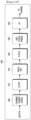
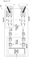
- FIGURE 4A is a high-level diagram of transmit path circuitry.
- the transmit path circuitry may be used for an orthogonal frequency division multiple access (OFDMA) communication.
- FIGURE 4B is a high-level diagram of receive path circuitry.
- the receive path circuitry may be used for an orthogonal frequency division multiple access (OFDMA) communication.
- the transmit path circuitry may be implemented in a base station (gNB) 102 or a relay station, and the receive path circuitry may be implemented in a user equipment (e.g., user equipment 116 of FIGURE 1 ).
- gNB base station
- the receive path circuitry may be implemented in a user equipment (e.g., user equipment 116 of FIGURE 1 ).
- the receive path circuitry 450 may be implemented in a base station (e.g., gNB 102 of FIGURE 1 ) or a relay station, and the transmit path circuitry may be implemented in a user equipment (e.g., user equipment 116 of FIGURE 1 ).
- a base station e.g., gNB 102 of FIGURE 1
- the transmit path circuitry may be implemented in a user equipment (e.g., user equipment 116 of FIGURE 1 ).
- Transmit path circuitry comprises channel coding and modulation block 405, serial-to-parallel (S-to-P) block 410, Size N Inverse Fast Fourier Transform (IFFT) block 415, parallel-to-serial (P-to-S) block 420, add cyclic prefix block 425, and up-converter (UC) 430.
- Receive path circuitry 450 comprises down-converter (DC) 455, remove cyclic prefix block 460, serial-to-parallel (S-to-P) block 465, Size N Fast Fourier Transform (FFT) block 470, parallel-to-serial (P-to-S) block 475, and channel decoding and demodulation block 480.
- DC down-converter
- FFT Fast Fourier Transform
- FIGURES 4A 400 and 4B 450 may be implemented in software, while other components may be implemented by configurable hardware or a mixture of software and configurable hardware.
- the FFT blocks and the IFFT blocks described in this disclosure document may be implemented as configurable software algorithms, where the value of Size N may be modified according to the implementation.
- the value of the N variable may be any integer number (i.e., 1, 4, 3, 4, etc.), while for FFT and IFFT functions, the value of the N variable may be any integer number that is a power of two (i.e., 1, 2, 4, 8, 16, etc.).
- channel coding and modulation block 405 receives a set of information bits, applies coding (e.g., LDPC coding) and modulates (e.g., quadrature phase shift keying (QPSK) or quadrature amplitude modulation (QAM)) the input bits to produce a sequence of frequency-domain modulation symbols.
- Serial-to-parallel block 410 converts (i.e., de-multiplexes) the serial modulated symbols to parallel data to produce N parallel symbol streams where N is the IFFT/FFT size used in BS 102 and UE 116.
- Size N IFFT block 415 then performs an IFFT operation on the N parallel symbol streams to produce time-domain output signals.
- Parallel-to-serial block 420 converts (i.e., multiplexes) the parallel time-domain output symbols from Size N IFFT block 415 to produce a serial time-domain signal.
- Add cyclic prefix block 425 then inserts a cyclic prefix to the time-domain signal.
- up-converter 430 modulates (i.e., up-converts) the output of add cyclic prefix block 425 to RF frequency for transmission via a wireless channel.
- the signal may also be filtered at baseband before conversion to RF frequency.
- the transmitted RF signal arrives at the UE 116 after passing through the wireless channel, and reverse operations to those at gNB 102 are performed.
- Down-converter 455 down-converts the received signal to baseband frequency and removes cyclic prefix block 460, and removes the cyclic prefix to produce the serial time-domain baseband signal.
- Serial-to-parallel block 465 converts the time-domain baseband signal to parallel time-domain signals.
- Size N FFT block 470 then performs an FFT algorithm to produce N parallel frequency-domain signals.
- Parallel-to-serial block 475 converts the parallel frequency-domain signals to a sequence of modulated data symbols.
- Channel decoding and demodulation block 480 demodulates and then decodes the modulated symbols to recover the original input data stream.
- Each of gNBs 101-103 may implement a transmit path that is analogous to transmitting in the downlink to user equipment 111-116 and may implement a receive path that is analogous to receiving in the uplink from user equipment 111-116.
- each one of user equipment 111-116 may implement a transmit path corresponding to the architecture for transmitting in the uplink to gNBs 101-103 and may implement a receive path corresponding to the architecture for receiving in the downlink from gNBs 101-103.
- enhanced mobile broadband eMBB
- ultra reliable and low latency URLL
- massive machine type communication mMTC is determined that a number of devices can be as many as 100,000 to 1 million per km2, but the reliability/throughput/latency requirement could be less stringent. This scenario may also involve power efficiency requirement as well, in that the battery consumption may be minimized as possible.
- a communication system includes a downlink (DL) that conveys signals from transmission points such as base stations (BSs) or NodeBs to user equipments (UEs) and an Uplink (UL) that conveys signals from UEs to reception points such as NodeBs.
- DL downlink
- UE user equipment
- UL Uplink
- a UE also commonly referred to as a terminal or a mobile station, may be fixed or mobile and may be a cellular phone, a personal computer device, or an automated device.
- An eNodeB which is generally a fixed station, may also be referred to as an access point or other equivalent terminology. For LTE systems, a NodeB is often referred as an eNodeB.
- DL signals can include data signals conveying information content, control signals conveying DL control information (DCI), and reference signals (RS) that are also known as pilot signals.
- DCI DL control information
- RS reference signals
- An eNodeB transmits data information through a physical DL shared channel (PDSCH).
- An eNodeB transmits DCI through a physical DL control channel (PDCCH) or an Enhanced PDCCH (EPDCCH).
- PDSCH physical DL shared channel
- EPCCH Enhanced PDCCH
- An eNodeB transmits acknowledgement information in response to data transport block (TB) transmission from a UE in a physical hybrid ARQ indicator channel (PHICH).
- An eNodeB transmits one or more of multiple types of RS including a UE-common RS (CRS), a channel state information RS (CSI-RS), or a demodulation RS (DMRS).
- CRS is transmitted over a DL system bandwidth (BW) and can be used by UEs to obtain a channel estimate to demodulate data or control information or to perform measurements.
- BW DL system bandwidth
- an eNodeB may transmit a CSI-RS with a smaller density in the time and/or frequency domain than a CRS.
- DMRS can be transmitted only in the BW of a respective PDSCH or EPDCCH and a UE can use the DMRS to demodulate data or control information in a PDSCH or an EPDCCH, respectively.
- a transmission time interval for DL channels is referred to as a subframe and can have, for example, duration of 1 millisecond.
- DL signals also include transmission of a logical channel that carries system control information.
- a BCCH is mapped to either a transport channel referred to as a broadcast channel (BCH) when the DL signals convey a master information block (MIB) or to a DL shared channel (DL-SCH) when the DL signals convey a System Information Block (SIB).
- MIB master information block
- DL-SCH DL shared channel
- SIB System Information Block
- Most system information is included in different SIBs that are transmitted using DL-SCH.
- a presence of system information on a DL-SCH in a subframe can be indicated by a transmission of a corresponding PDCCH conveying a codeword with a cyclic redundancy check (CRC) scrambled with system information RNTI (SI-RNTI).
- SI-RNTI system information RNTI
- SIB-1 scheduling information for the first SIB (SIB-1) can be provided by the MIB.
- a DL resource allocation is performed in a unit of subframe and a group of physical resource blocks (PRBs).
- a transmission BW includes frequency resource units referred to as resource blocks (RBs).
- Each RB includes N sc RB sub-carriers, or resource elements (REs), such as 12 REs.
- a unit of one RB over one subframe is referred to as a PRB.
- UL signals can include data signals conveying data information, control signals conveying UL control information (UCI), and UL RS.
- UL RS includes DMRS and Sounding RS (SRS).
- a UE transmits DMRS only in a BW of a respective PUSCH or PUCCH.
- An eNodeB can use a DMRS to demodulate data signals or UCI signals.
- a UE transmits SRS to provide an eNodeB with an UL CSI.
- a UE transmits data information or UCI through a respective physical UL shared channel (PUSCH) or a Physical UL control channel (PUCCH). If a UE needs to transmit data information and UCI in a same UL subframe, the UE may multiplex both in a PUSCH.
- PUSCH physical UL shared channel
- PUCCH Physical UL control channel
- UCI includes Hybrid Automatic Repeat request acknowledgement (HARQ-ACK) information, indicating correct (ACK) or incorrect (NACK) detection for a data TB in a PDSCH or absence of a PDCCH detection (DTX), scheduling request (SR) indicating whether a UE has data in the UE's buffer, rank indicator (RI), and channel state information (CSI) enabling an eNodeB to perform link adaptation for PDSCH transmissions to a UE.
- HARQ-ACK information is also transmitted by a UE in response to a detection of a PDCCH/EPDCCH indicating a release of semi-persistently scheduled PDSCH.
- An UL subframe includes two slots. Each slot includes N symb UL symbols for transmitting data information, UCI, DMRS, or SRS.
- a frequency resource unit of an UL system BW is a RB.
- a UE is allocated N RB RBs for a total of N RB ⁇ N sc RB REs for a transmission BW.
- N RB 1.
- a last subframe symbol can be used to multiplex SRS transmissions from one or more UEs.
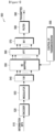
- FIGURE 5 illustrates a transmitter block diagram 500 for a PDSCH in a subframe according to embodiments of the present disclosure.
- the embodiment of the transmitter block diagram 500 illustrated in FIGURE 5 is for illustration only.
- One or more of the components illustrated in FIGURE 5 can be implemented in specialized circuitry configured to perform the noted functions or one or more of the components can be implemented by one or more processors executing instructions to perform the noted functions.
- FIGURE 5 does not limit the scope of this disclosure to any particular implementation of the transmitter block diagram 500.
- information bits 510 are encoded by encoder 520, such as a turbo encoder, and modulated by modulator 530, for example using quadrature phase shift keying (QPSK) modulation.
- a serial to parallel (S/P) converter 540 generates M modulation symbols that are subsequently provided to a mapper 550 to be mapped to REs selected by a transmission BW selection unit 555 for an assigned PDSCH transmission BW, unit 560 applies an Inverse fast Fourier transform (IFFT), the output is then serialized by a parallel to serial (P/S) converter 570 to create a time domain signal, filtering is applied by filter 580, and a signal transmitted 590.
- Additional functionalities such as data scrambling, cyclic prefix insertion, time windowing, interleaving, and others are well known in the art and are not shown for brevity.
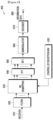
- FIGURE 6 illustrates a receiver block diagram 600 for a PDSCH in a subframe according to embodiments of the present disclosure.
- the embodiment of the diagram 600 illustrated in FIGURE 6 is for illustration only.
- One or more of the components illustrated in FIGURE 6 can be implemented in specialized circuitry configured to perform the noted functions or one or more of the components can be implemented by one or more processors executing instructions to perform the noted functions.
- FIGURE 6 does not limit the scope of this disclosure to any particular implementation of the diagram 600.
- a received signal 610 is filtered by filter 620, REs 630 for an assigned reception BW are selected by BW selector 635, unit 640 applies a fast Fourier transform (FFT), and an output is serialized by a parallel-to-serial converter 650.
- a demodulator 660 coherently demodulates data symbols by applying a channel estimate obtained from a DMRS or a CRS (not shown), and a decoder 670, such as a turbo decoder, decodes the demodulated data to provide an estimate of the information data bits 680. Additional functionalities such as time-windowing, cyclic prefix removal, de-scrambling, channel estimation, and de-interleaving are not shown for brevity.
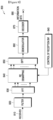
- FIGURE 7 illustrates a transmitter block diagram 700 for a PUSCH in a subframe according to embodiments of the present disclosure.
- the embodiment of the block diagram 700 illustrated in FIGURE 7 is for illustration only.
- One or more of the components illustrated in FIGURE 5 can be implemented in specialized circuitry configured to perform the noted functions or one or more of the components can be implemented by one or more processors executing instructions to perform the noted functions.
- FIGURE 7 does not limit the scope of this disclosure to any particular implementation of the block diagram 700.
- information data bits 710 are encoded by encoder 720, such as a turbo encoder, and modulated by modulator 730.
- a discrete Fourier transform (DFT) unit 740 applies a DFT on the modulated data bits, REs 750 corresponding to an assigned PUSCH transmission BW are selected by transmission BW selection unit 755, unit 760 applies an IFFT and, after a cyclic prefix insertion (not shown), filtering is applied by filter 770 and a signal transmitted 780.
- DFT discrete Fourier transform
- FIGURE 8 illustrates a receiver block diagram 800 for a PUSCH in a subframe according to embodiments of the present disclosure.
- the embodiment of the block diagram 800 illustrated in FIGURE 8 is for illustration only.
- One or more of the components illustrated in FIGURE 8 can be implemented in specialized circuitry configured to perform the noted functions or one or more of the components can be implemented by one or more processors executing instructions to perform the noted functions.
- FIGURE 8 does not limit the scope of this disclosure to any particular implementation of the block diagram 800.
- a received signal 810 is filtered by filter 820. Subsequently, after a cyclic prefix is removed (not shown), unit 830 applies a FFT, REs 840 corresponding to an assigned PUSCH reception BW are selected by a reception BW selector 845, unit 850 applies an inverse DFT (IDFT), a demodulator 860 coherently demodulates data symbols by applying a channel estimate obtained from a DMRS (not shown), a decoder 870, such as a turbo decoder, decodes the demodulated data to provide an estimate of the information data bits 880.
- a decoder 870 such as a turbo decoder
- next generation cellular systems various use cases are envisioned beyond the capabilities of LTE system.
- 5G or the fifth generation cellular system a system capable of operating at sub-6GHz and above-6 GHz (for example, in mmWave regime) becomes one of the requirements.
- 3GPP TR 22.891 74 5G use cases have been identified and described; those use cases can be roughly categorized into three different groups.
- a first group is termed “enhanced mobile broadband (eMBB),” targeted to high data rate services with less stringent latency and reliability requirements.
- eMBB enhanced mobile broadband
- URLL ultra-reliable and low latency
- a third group is termed “massive MTC (mMTC)” targeted for large number of low-power device connections such as 1 million per km 2 with less stringent the reliability, data rate, and latency requirements.
- mMTC massive MTC
- FIGURE 9 illustrates an example network configuration 900 according to embodiments of the present disclosure.
- the embodiment of the network configuration 900 illustrated in FIGURE 9 is for illustration only.
- FIGURE 9 does not limit the scope of this disclosure to any particular implementation of the configuration 900.
- an operator's network 910 includes a number of radio access network(s) 920 (RAN(s)) that are associated with network devices such as gNBs 930a and 930b, small cell base stations (femto/pico gNBs or Wi-Fi access points) 935a and 935b.
- the network 910 can support various services, each represented as a slice.
- an URLL slice 940a serves UEs requiring URLL services such as cars 945b, trucks 945c, smart watches 945a, and smart glasses 945d.
- Two mMTC slices 950a and 950b serve UEs requiring mMTC services such as power meters 955a, and temperature control box 955b.
- One eMBB slice 960a serves UEs requiring eMBB services such as cells phones 965a, laptops 965b, and tablets 965c.
- a device configured with two slices can also be envisioned.
- FIGURE 10 illustrates an example multiplexing of two slices 1000 according to embodiments of the present disclosure.
- the embodiment of the multiplexing of two slices 1000 illustrated in FIGURE 10 is for illustration only.
- One or more of the components illustrated in FIGURE 10 can be implemented in specialized circuitry configured to perform the noted functions or one or more of the components can be implemented by one or more processors executing instructions to perform the noted functions.
- FIGURE 10 does not limit the scope of this disclosure to any particular implementation of the multiplexing of two slices 1000.
- a slice can be composed of one or two transmission instances where one transmission instance includes a control (CTRL) component (e.g., 1020a, 1060a, 1060b, 1020b, or 1060c) and a data component (e.g., 1030a, 1070a, 1070b, 1030b, or 1070c).
- CTRL control
- the two slices are multiplexed in frequency domain whereas in embodiment 1050, the two slices are multiplexed in time domain.
- the 3GPP NR specification supports up to 32 CSI-RS antenna ports which enable a gNB to be equipped with a large number of antenna elements (such as 64 or 128). In this case, a plurality of antenna elements is mapped onto one CSI-RS port. For next generation cellular systems such as 5G, the maximum number of CSI-RS ports can either remain the same or increase.
- FIGURE 11 illustrates an example antenna blocks 1100 according to embodiments of the present disclosure.
- the embodiment of the antenna blocks 1100 illustrated in FIGURE 11 is for illustration only.
- FIGURE 11 does not limit the scope of this disclosure to any particular implementation of the antenna blocks 1100.
- the number of CSI-RS ports - which can correspond to the number of digitally precoded ports - tends to be limited due to hardware constraints (such as the feasibility to install a large number of ADCs/DACs at mmWave frequencies) as illustrated in FIGURE 11 .
- one CSI-RS port is mapped onto a large number of antenna elements which can be controlled by a bank of analog phase shifters.
- One CSI-RS port can then correspond to one sub-array which produces a narrow analog beam through analog beamforming. This analog beam can be configured to sweep across a wider range of angles by varying the phase shifter bank across symbols or subframes.
- the number of sub-arrays (equal to the number of RF chains) is the same as the number of CSI-RS ports N CSI-PORT .
- a digital beamforming unit performs a linear combination across N CSI-PORT analog beams to further increase precoding gain. While analog beams are wideband (hence not frequency-selective), digital precoding can be varied across frequency sub-bands or resource blocks.
- NP non-precoded
- CSI-RS For non-precoded (NP) CSI-RS, a cell-specific one-to-one mapping between CSI-RS port and TXRU is utilized. Different CSI-RS ports have the same wide beam width and direction and hence generally cell wide coverage.
- beamformed CSI-RS beamforming operation, either cell-specific or UE-specific, is applied on a non-zero-power (NZP) CSI-RS resource (e.g., comprising multiple ports). At least at a given time/frequency, CSI-RS ports have narrow beam widths and hence not cell wide coverage, and at least from the gNB perspective. At least some CSI-RS port-resource combinations have different beam directions.
- NZP non-zero-power
- UE-specific BF CSI-RS can be readily used. This is typically feasible when UL-DL duplex distance is sufficiently small. When this condition does not hold, however, some UE feedback is necessary for the eNodeB to obtain an estimate of DL long-term channel statistics (or any of representation thereof).
- T1 periodicity
- T2 periodicity
- MIMO has been identified as an essential feature in order to achieve high system throughput requirements and it will continue to be the same in NR.
- One of the key components of a MIMO transmission scheme is the accurate CSI acquisition at the eNB (or TRP).
- TRP the eNB
- the availability of accurate CSI is necessary in order to guarantee high MU performance.
- the CSI can be acquired using the SRS transmission relying on the channel reciprocity.
- the CSI can be acquired using the CSI-RS transmission from the eNB, and CSI acquisition and feedback from the UE.
- the CSI feedback framework is ' implicit ' in the form of CQI/PMI/RI derived from a codebook assuming SU transmission from the eNB. Because of the inherent SU assumption while deriving CSI, this implicit CSI feedback is inadequate for MU transmission. Since future (e.g., NR) systems are likely to be more MU-centric, this SU-MU CSI mismatch will be a bottleneck in achieving high MU performance gains. Another issue with implicit feedback is the scalability with larger number of antenna ports at the eNB. For large number of antenna ports, the codebook design for implicit feedback is quite complicated, and the designed codebook is not guaranteed to bring justifiable performance benefits in practical deployment scenarios (for example, only a small percentage gain can be shown at the most).
- Type I CSI reporting In addition to Type I, a high-resolution CSI reporting, referred to as Type II CSI reporting, is also supported to provide more accurate CSI information to gNB for use cases such as high-order MU-MIMO.
- FIGURE 12 illustrates an example antenna port layout 1200 according to embodiments of the present disclosure.
- the embodiment of the antenna port layout 1200 illustrated in FIGURE 12 is for illustration only.
- FIGURE 12 does not limit the scope of this disclosure to any particular implementation of the antenna port layout 1200.
- N 1 and N 2 are the number of antenna ports with the same polarization in the first and second dimensions, respectively.
- N 1 >1, N 2 >1, and for 1D antenna port layouts N 1 >1 and N 2 1. Therefore, for a dual-polarized antenna port layout, the total number of antenna ports is 2 N 1 N 2 .
- a UE is configured with high-resolution (e.g., Type II) CSI reporting in which the linear combination based Type II CSI reporting framework is extended to include a frequency dimension in addition to the first and second antenna port dimensions.
- high-resolution e.g., Type II
- FIGURE 13 illustrates a 3D grid 1300 of the oversampled DFT beams (1st port dim., 2nd port dim., freq. dim.) in which
- the basis sets for 1 st and 2 nd port domain representation are oversampled DFT codebooks of length- N 1 and length- N 2 , respectively, and with oversampling factors O 1 and O 2 , respectively.
- the basis set for frequency domain representation (i.e., 3rd dimension) is an oversampled DFT codebook of length- N 3 and with oversampling factor O 3 .
- the oversampling factors O i belons to ⁇ 2, 4, 8 ⁇ .
- at least one of O 1 , O 2 , and O 3 is higher layer configured (via RRC signaling).
- M i is the number of coefficients c l,i,m reported by the UE for a given i , where M i ⁇ M (where ⁇ M i ⁇ or ⁇ M i is either fixed, configured by the gNB or reported by the UE).
- discrete cosine transform DCT basis is used to construct/report basis B for the 3 rd dimension.
- the L antenna ports per polarization or column vectors of A are selected by the index q 1 , where q 1 ⁇ 0 , 1 , ⁇ , ⁇ P CSI ⁇ RS 2 d ⁇ ⁇ 1 (this requires ⁇ log 2 ⁇ P CSI ⁇ RS 2 d ⁇ ⁇ bits), and the value of d is configured with the higer layer parameter PortSelectionSamplingSize , where d ⁇ ⁇ 1,2,3,4 ⁇ and d ⁇ min P CSI ⁇ RS 2 L .
- the amplitude coefficient ( p l,i,m ) is reported using an A-bit amplitude codebook where A belongs to ⁇ 2, 3, 4 ⁇ . If multiple values for A are supported, then one value is configured via higher layer signaling.
- LC linear combination
- SD spatial domain
- FD frequency domain
- ( L l , M l ) denotes the number of SD and FD basis vectors for layer l .
- L l L .
- ⁇ l ⁇ for rank 1-2.
- ⁇ l for rank > 2 is either fixed (based on ⁇ for rank 1-2) or higher layer configured.
- the remaining 2 L l M l - K NZ,l coefficients that are not reported by the UE are assumed to be zero.
- the following quantization scheme is used to quantize/report the K NZ,l NZ coefficients for each layer l .
- a UE can be configured to report M FD basis vectors
- M ⁇ p ⁇ N 3 R ⁇ , where R is higher-layer configured from ⁇ 1,2 ⁇ and p is higher-layer configured from 1 4 1 2 .
- the p value is higher-layer configured for rank 1-2 CSI reporting.
- rank > 2 e.g., rank 3-4
- the p value (denoted by v 0 ) can be differnet.
- a UE can be configured to report M FD basis vectors in one-step from N 3 orthogonal DFT basis vectors freely (independently) for each layer l ⁇ ⁇ 0,1,..., v -1 ⁇ of a rank v CSI reporting.
- a UE can be configured to report M FD basis vectors in two-step as follows:
- a one-step method is used when N 3 ⁇ 19 and a two -step method is used when N 3 > 19.
- N 3 ′ ⁇ ⁇ M ⁇ where ⁇ > 1 is configurable.
- the codebook parameters used in the DFT based frequency domain compression are ( L , p , v 0 , ⁇ , ⁇ , N ph ).
- the set of values for these codebook parameters are as follows:
- This disclosure proposes example embodiments for configuring these codebook parameters ( L , p , v 0 , ⁇ , ⁇ , N ph ).
- this configuration is via higher layer (e.g., RRC) signaling.
- a UE is configured with codebook parameters ( L , p , v 0 , ⁇ , ⁇ , N ph )via a separate configuration entity (or field or state or configuration parameter) for each codebook parameter.
- codebook parameters L , p , v 0 , ⁇ , ⁇ , N ph
- the number of separate configuration entities equals the number of codebook parameters (6).
- An example of separate configuration entity (CE) is shown in Table 1.
- Table 1 An example of separate configuration entities Configuration entity (CE) Codebook parameter Candidate values CE1 L ⁇ 2,4,6 ⁇ CE2 p 1 2 1 4 CE3 v 0 1 4 1 8 CE4 ⁇ 1 4 1 2 3 4 CE5 ⁇ ⁇ 1.5,2 ⁇ CE6 N ph ⁇ 8,16 ⁇
- CE Configuration entity
- a UE is configured with codebook parameters ( L , p , v 0 , ⁇ , ⁇ , N ph ) via a single (joint) configuration entity for all codebook parameters.
- codebook parameters L , p , v 0 , ⁇ , ⁇ , N ph
- the number of configuration entity is one.
- An example of joint configuration entity (CE) is shown in Table 2.
- a UE is configured with codebook parameters ( L , p , v 0 , ⁇ , ⁇ , N ph ) via two sets (S1 and S2) of configuration entities, where:
- the number of configuration entities equals x 1 + x 2 .
- Table 3 An example of two sets of configuration entities is shown in Table 3.
- Table 3 An example of two sets of configuration entities Codebook parameter values Codebook parameter values Codebook parameter values CE2 value L p (rank 1-2) v 0 (rank 3-4) ⁇ ⁇ CE1 value N ph x0 2 1/4 1/8 1/4 1.5 0 8 x1 2 1/4 1/8 3/4 1.5 1 16 x2 4 1/4 1/8 1/4 2.5 x3 4 1/4 1/8 1/2 2.5 x4 4 1/4 1/4 3/4 2.5 x5 4 1/2 1/4 1/2 2.5 x6 6 1/4 - 1/4 2.5 x7 6 1/4 - 1/2 2.5 x8 6 1/4 - 3/4 2.5 where the CE2 value (or joint RRC parameter) is configured from a set of values ⁇ x0, x1, ..., x8 ⁇ . In one example, x0, x1, ..., x8 sequentially map to 0, 1, ...., 8, respectively. In one example, x0, x1, ..., x8 sequentially map to 1, 2, ...., 9, respectively.
- Table 4 An example of two sets of configuration entities is shown in Table 4.
- Table 4 An example of two sets of configuration entities Codebook parameter values Codebook parameter values Codebook parameter values Codebook parameter values Codebook parameter values CE3 value L p (rank 1-2) v 0 (rank 3-4) ⁇ CE1 value ⁇ CE2 value N ph x0 2 1/4 1/8 1/4 0 1.5 0 8 x1 2 1/4 1/8 3/4 1 2 1 16 x2 4 1/4 1/8 1/4 x3 4 1/4 1/8 1/2 x4 4 1/4 1/4 3/4 3/4 x5 4 1/2 1/4 1/2 x6 6 1/4 - 1/4 x7 6 1/4 - 1/2 x8 6 1/4 - 3/4 where the CE3 value (or joint RRC parameter) is configured from a set of values ⁇ x0, x1, ..., x8 ⁇ . In one example, x0, x1, ..., x8 sequentially map to 0, 1, ...., 8, respectively. In one example, x0, x1, ..., x8 sequentially map to 1, 2, ...., 9, respectively.
- the ⁇ values (1.5,2) in Table 3 and Table 4 are replaced with (2, 2.5) or (1.5,2.5).
- a UE is configured with codebook parameters ( L , p , v 0 , ⁇ , ⁇ , N ph ) via two sets (S1 and S2), where:
- the number of configuration entities equals x 1 .
- An example of the configuration entity is CE2 in Table 3.
- An example of the configuration entity is CE2 in Table 4.
- An example of the configuration entity is CE in Table 5.
- codebook parameters ( L , p , v 0 , ⁇ ) corresponding to CE values ⁇ x 0 , and x 2 - x 7 ⁇ i Table 5 are included those, CE3 values ⁇ x 0 , and x 2 - x 5 , x 7 , x 8 ⁇ , n Table 4.
- Table 5 An example of two sets of configuration entities Codebook parameter values CE value L p (rank 1-2) v 0 (rank 3-4) ⁇ x0 2 1/4 1/8 1/4 x1 2 1/4 1/8 1/2 x2 4 1/4 1/8 1/4 x3 4 1/4 1/8 1/2 x4 4 1/4 1/4 3/4 3/4 x5 4 1/2 1/4 1/2 x6 6 1/4 - 1/2 x7 6 1/4 - 3/4 where the CE value (or joint RRC parameter) is configured from a set of values ⁇ x0, x1, ..., x7 ⁇ . In one example, x0, x1, ..., x7 sequentially map to 0, 1, ...., 7, respectively. In one example, x0, x1, ..., x7 sequentially map to 1, 2, ...., 8, respectively.
- ⁇ values (1.5, 2) in Table 3 and Table 4 are replaced with (2, 2.5) or (1.5, 2.5).
- a UE is configured with codebook parameters ( L , p , v 0 , ⁇ , ⁇ , N ph ) via two sets (S1 and S2), where:
- the number of configuration entities equals x 1 .
- a UE is configured with codebook parameters ( L , p , v 0 , ⁇ , ⁇ , N ph ) via three sets (S1, S2, and S3), where:
- the number of configuration entities equals x 1 + x 2 .
- An example of configuration entities is shown in Table 6.
- Table 6 An example of configuration entities Codebook parameter values Codebook parameter values Codebook parameter values CE1 value L p (rank 1-2) v 0 (rank 3-4) ⁇ CE2 value N ph x0 2 1/4 1/8 1/4 0 8 x1 2 1/4 1/8 3/4 1 16 x2 4 1/4 1/8 1/4 x3 4 1/4 1/8 1/2 x4 4 1/4 1/4 3/4 3/4 x5 4 1/2 1/4 1/2 x6 6 1/4 - 1/4 x7 6 1/4 - 1/2 x8 6 1/4 - 3/4 where the CE1 value (or joint RRC parameter) is configured from a set of values ⁇ x0, x1, ..., x8 ⁇ . In one example, x0, x1, ..., x8 sequentially map to 0, 1, ...., 8, respectively. In one example, x0, x1, ..., x8 sequentially map to 1, 2, ...., 9, respectively.
- An example of configuration entities is shown in Table 7.
- Table 7 An example of configuration entities Codebook parameter values Codebook parameter values Codebook parameter values Codebook parameter values Codebook parameter values CE3 value L p (rank 1-2) v 0 (rank 3-4) CE1 value ⁇ CE2 value N ph x0 2 1/4 1/8 0 1/4 0 8 x1 4 1/4 1/8 1 1/2 1 16 x2 4 1/4 1/4 2 3/4 x3 4 1/2 1/4 x4 6 1/4 - where the CE3 value (or joint RRC parameter) is configured from a set of values ⁇ x0, x1, ..., x4 ⁇ . In one example, x0, x1, ..., x4 sequentially map to 0, 1, ...., 4, respectively. In one example, x0, x1, ..., x4 sequentially map to 1, 2, ...., 5, respectively.
- FIGURE 14 illustrates a flow chart of a method 1400 for operating a user equipment (UE) for channel state information (CSI) reporting in a wireless communication system, as may be performed by a UE such as UE 116, according to embodiments of the present disclosure.
- the embodiment of the method 1400 illustrated in FIGURE 14 is for illustration only.
- FIGURE 13 does not limit the scope of this disclosure to any particular implementation.
- the method 1400 begins at step 1402.
- the UE e.g., 111-116 as illustrated in FIGURE 1
- receives from a base station (BS), channel state information (CSI) feedback configuration information including codebook parameters configured jointly via a single radio resource control (RRC) parameter, the codebook parameters comprising L , p , v 0 , and ⁇ , where the parameter L determines a number of spatial domain (SD) basis vectors, the parameter ⁇ determines a maximum number of coefficients, and the parameters p and v 0 determine a number ( M v ) of frequency domain (FD) basis vectors, wherein the parameter p is for a first rank set and the parameter v 0 is for a second rank set.
- BS base station
- RRC radio resource control
- step 1404 the UE generates the CSI feedback based on the CSI feedback configuration information, where the CSI feedback is generated for a rank value v from one of the first and second rank sets.
- step 1406 the UE transmits, to the BS, the CSI feedback over an uplink channel.
- a mapping of the codebook parameters configured jointly via the single RRC parameter is determined based on a table given by: Codebook parameters' values RRC parameter value L p (first rank set) v 0 (second rank set) ⁇ x0 2 1/4 1/8 1/4 x1 2 1/4 1/8 1/2 x2 4 1/4 1/8 1/4 x3 4 1/4 1/8 1/2 x4 4 1/4 1/4 3/4 3/4 x5 4 1/2 1/4 1/2 x6 6 1/4 - 1/2 x7 6 1/4 - 3/4 wherein the UE is configured with a value of the single RRC parameter that is configured from a set of values ⁇ x0, x1, ..., x7 ⁇ .
- CSI-RS channel state information reference signal
- the CSI feedback includes a set of M v FD basis vectors, where M v is determined based on the parameter p if the rank value v belongs to the first rank set and based on the parameter v 0 if the rank value v belongs to the second rank set.
- the first rank set comprises rank values ⁇ 1,2 ⁇ and the second rank set comprises rank values ⁇ 3,4 ⁇ .
- M ⁇ ⁇ q ⁇ N 3 R ⁇
- ⁇ ⁇ is a ceiling function
- N 3 is a total number of FD units
- R is a maximum number of FD units in each subband configured for the CSI feedback.
- FIGURE 15 illustrates a flow chart of another method 1500, as may be performed by a base station (BS) such as BS 102, according to embodiments of the present disclosure.
- BS base station
- the embodiment of the method 1500 illustrated in FIGURE 15 is for illustration only.
- FIGURE 15 does not limit the scope of this disclosure to any particular implementation.
- the BS transmits, to a user equipment (UE), the CSI feedback configuration information including codebook parameters configured jointly via a single radio resource control (RRC) parameter, the codebook parameters comprising L , p , v 0 , and ⁇ , where the parameter L determines a number of spatial domain (SD) basis vectors, the parameter ⁇ determines a maximum number of coefficients, and the parameters p and v 0 determine a number ( M v ) of frequency domain (FD) basis vectors, wherein the parameter p is for a first rank set and the parameter v 0 is for a second rank set.
- RRC radio resource control
- the BS transmits channel state information (CSI) feedback configuration information to a user equipment (UE).
- CSI channel state information
- a mapping of the codebook parameters configured jointly via the single RRC parameter is determined based on a table given by: Codebook parameters' values RRC parameter value L p (first rank set) v 0 (second rank set) ⁇ x0 2 1/4 1/8 1/4 x1 2 1/4 1/8 1/2 x2 4 1/4 1/8 1/4 x3 4 1/4 1/8 1/2 x4 4 1/4 1/4 3/4 3/4 x5 4 1/2 1/4 1/2 x6 6 1/4 - 1/2 x7 6 1/4 - 3/4 wherein the UE is configured with a value of the single RRC parameter that is configured from a set of values ⁇ x0, x1, ..., x7 ⁇ .
- CSI-RS channel state information reference signal
- the CSI feedback includes a set of M v FD basis vectors, where M v is determined based on the parameter p if the rank value v belongs to the first rank set and based on the parameter v 0 if the rank value v belongs to the second rank set.
- M ⁇ ⁇ q ⁇ N 3 R ⁇ R
- ⁇ ⁇ is a ceiling function
- N 3 is a total number of FD units
- R is a maximum number of FD units in each subband configured for the CSI feedback.
- a first aspect of the present invention is directed to a method for operating a user equipment (UE) for channel state information (CSI) feedback in a wireless communication system, the method comprising receiving a radio resource control (RRC) parameter indicating a combination of codebook parameters via higher layer signaling, the codebook parameters comprising L , p , v 0 , and ⁇ ; generating the CSI feedback based on the RRC parameter, wherein the CSI feedback is generated for a rank value v from one of first and second rank sets; and transmitting the CSI feedback over an uplink channel.
- RRC radio resource control
- a mapping of the combination of the codebook parameters to the RRC parameter is determined based on a table given by: Codebook parameters' values RRC parameter value L p (first rank set) v 0 (second rank set) ⁇ x0 2 1/4 1/8 1/4 x1 2 1/4 1/8 1/2 x2 4 1/4 1/8 1/4 x3 4 1/4 1/8 1/2 x4 4 1/4 1/4 3/4 3/4 x5 4 1/2 1/4 1/2 x6 6 1/4 - 1/2 x7 6 1/4 - 3/4 wherein the UE is configured with a value of the RRC parameter that is configured from a set of values ⁇ x0, x1, ..., x7 ⁇ .
- the UE is not expected to be configured with a value of the RRC parameter being x6 or x7, when the UE is configured with less than 32 channel state information reference signal (CSI-RS) antenna ports.
- CSI-RS channel state information reference signal
- the UE is not expected to be configured with a value of the RRC parameter being x6 or x7, when the UE is allowed to report the rank value v > 2.
- the parameter L determines a number of spatial domain (SD) basis vectors
- the parameter ⁇ determines a maximum number of non-zero coefficients
- the parameters p and v 0 determine a number ( M v ) of frequency domain (FD) basis vectors
- the parameter p is for the first rank set and the parameter v 0 is for the second rank set
- the first rank set comprises rank values ⁇ 1,2 ⁇ and the second rank set comprises rank values ⁇ 3,4 ⁇ .
- PMI precoding matrix indicator
- a l [ a l, 0 a l, 1 ⁇ a l,L- 1 ] comprises L basis vectors for SD antenna ports, a l,i is a N 1 N 2 ⁇ 1 column vector, where N 1 and N 2 are number of antenna ports, respectively, with a same antenna polarization in a first and a second dimensions of a two-dimensional dual-polarized channel state information-reference signal (CSI-RS) antenna ports at the BS;
- B l [ b l, 0 b l, 1 ⁇ b l , Mv -1 ] comprises M v basis vectors for FD units, b l,k is a N 3 ⁇ 1 column vector:
- C l is a 2 L ⁇ M v matrix comprising complex coefficients c l,i,k ; and the total number ( N 3 ) of the FD units is determined based on the value of R and a number of subbands configured for the CSI feedback, wherein: M
- a second aspect of the present invention is directed to a method for operating a base station (BS) for channel state information (CSI) feedback in a wireless communication system, the method comprising: generating a radio resource control (RRC) parameter indicating a combination of codebook parameters, the codebook parameters comprising L,p,v 0 , and ⁇ ; transmitting the single RRC parameter via higher layer signaling; and receiving, over an uplink channel, a CSI feedback generated for a rank value v from one of first and second rank sets, wherein the CSI feedback is generated based on the RRC parameter.
- RRC radio resource control
- a mapping of the combination of the codebook parameters to the RRC parameter is determined based on a table given by: Codebook parameters' values RRC parameter value L p (first rank set) v 0 (second rank set) ⁇ x0 2 1/4 1/8 1/4 x1 2 1/4 1/8 1/2 x2 4 1/4 1/8 1/4 x3 4 1/4 1/8 1/2 x4 4 1/4 1/4 3/4 3/4 x5 4 1/2 1/4 1/2 x6 6 1/4 - 1/2 x7 6 1/4 - 3/4 wherein the UE is configured with a value of the RRC parameter that is configured from a set of values ⁇ x0, x1, ..., x7 ⁇ .
- CSI-RS channel state information reference signal
- the parameter L determines a number of spatial domain (SD) basis vectors
- the parameter ⁇ determines a maximum number of non-zero coefficients
- the parameters p and v 0 determine a number ( M v ) of frequency domain (FD) basis vectors
- the parameter p is for the first rank set and the parameter v 0 is for the second rank set.
- a third aspect of the present invention is directed to user equipment (UE) for channel state information (CSI) feedback in a wireless communication system, the UE comprising: a transceiver configured to receive a radio resource control (RRC) parameter indicating a combination of codebook parameters from higher layer, the codebook parameters comprising L , p , v 0 , and ⁇ ; and a processor operably connected to the transceiver, the processor configured to generate the CSI feedback based on the RRC parameter, wherein the CSI feedback is generated for a rank value v from one of first and second rank sets; wherein the transceiver is further configured to transmit the CSI feedback over an uplink channel.
- RRC radio resource control
Landscapes
- Engineering & Computer Science (AREA)
- Signal Processing (AREA)
- Computer Networks & Wireless Communication (AREA)
- Physics & Mathematics (AREA)
- Mathematical Physics (AREA)
- Mobile Radio Communication Systems (AREA)
Applications Claiming Priority (5)
| Application Number | Priority Date | Filing Date | Title |
|---|---|---|---|
| US201962884467P | 2019-08-08 | 2019-08-08 | |
| US201962892102P | 2019-08-27 | 2019-08-27 | |
| US16/947,044 US11277187B2 (en) | 2019-08-08 | 2020-07-15 | Method and apparatus for CSI parameter configuration in wireless communication systems |
| PCT/KR2020/010507 WO2021025538A1 (en) | 2019-08-08 | 2020-08-07 | Method and apparatus for csi parameter configuration in wireless communication systems |
| EP20849470.8A EP3997804B1 (de) | 2019-08-08 | 2020-08-07 | Verfahren und vorrichtung zur csi-parameterkonfiguration in einem drahtloskommunikationssystem |
Related Parent Applications (1)
| Application Number | Title | Priority Date | Filing Date |
|---|---|---|---|
| EP20849470.8A Division EP3997804B1 (de) | 2019-08-08 | 2020-08-07 | Verfahren und vorrichtung zur csi-parameterkonfiguration in einem drahtloskommunikationssystem |
Publications (2)
| Publication Number | Publication Date |
|---|---|
| EP4404498A2 true EP4404498A2 (de) | 2024-07-24 |
| EP4404498A3 EP4404498A3 (de) | 2024-10-16 |
Family
ID=74498794
Family Applications (2)
| Application Number | Title | Priority Date | Filing Date |
|---|---|---|---|
| EP20849470.8A Active EP3997804B1 (de) | 2019-08-08 | 2020-08-07 | Verfahren und vorrichtung zur csi-parameterkonfiguration in einem drahtloskommunikationssystem |
| EP24181471.4A Pending EP4404498A3 (de) | 2019-08-08 | 2020-08-07 | Verfahren und vorrichtung zur csi-parameterkonfiguration in drahtlosen kommunikationssystemen |
Family Applications Before (1)
| Application Number | Title | Priority Date | Filing Date |
|---|---|---|---|
| EP20849470.8A Active EP3997804B1 (de) | 2019-08-08 | 2020-08-07 | Verfahren und vorrichtung zur csi-parameterkonfiguration in einem drahtloskommunikationssystem |
Country Status (6)
| Country | Link |
|---|---|
| US (2) | US11277187B2 (de) |
| EP (2) | EP3997804B1 (de) |
| JP (1) | JP7638959B2 (de) |
| KR (1) | KR20210018781A (de) |
| CN (1) | CN114342278B (de) |
| WO (1) | WO2021025538A1 (de) |
Families Citing this family (13)
| Publication number | Priority date | Publication date | Assignee | Title |
|---|---|---|---|---|
| EP3892050A4 (de) * | 2020-02-12 | 2022-01-05 | Apple Inc. | Kanalzustandsinformationsmeldung |
| CN116711364A (zh) * | 2021-01-17 | 2023-09-05 | 华为技术有限公司 | 信道信息获取方法及相关设备 |
| WO2022183339A1 (zh) * | 2021-03-01 | 2022-09-09 | Oppo广东移动通信有限公司 | 无线通信方法和设备 |
| CN115333586B (zh) * | 2021-05-11 | 2024-07-19 | 大唐移动通信设备有限公司 | 码本指示方法、装置及存储介质 |
| CN115441914A (zh) * | 2021-06-01 | 2022-12-06 | 华为技术有限公司 | 一种通信方法及装置 |
| US11923944B2 (en) * | 2021-06-04 | 2024-03-05 | Samsung Electronics Co., Ltd. | Method and apparatus for frequency selective UL precoding |
| CN115603877A (zh) * | 2021-07-09 | 2023-01-13 | 中兴通讯股份有限公司(Cn) | 信道状态信息报告、接收方法、通信节点及存储介质 |
| US20230246688A1 (en) * | 2022-02-02 | 2023-08-03 | Samsung Electronics Co., Ltd. | Method and apparatus for csi codebook |
| US20230344491A1 (en) * | 2022-04-21 | 2023-10-26 | Samsung Electronics Co., Ltd. | Method and apparatus for csi codebook parameters |
| WO2024119382A1 (zh) * | 2022-12-06 | 2024-06-13 | 北京小米移动软件有限公司 | 信道状态信息上报方法、装置及存储介质 |
| WO2024176437A1 (ja) * | 2023-02-24 | 2024-08-29 | 株式会社Nttドコモ | 端末、無線通信方法及び基地局 |
| WO2025020120A1 (en) * | 2023-07-26 | 2025-01-30 | Qualcomm Incorporated | Enhanced type-ii channel state information (csi) with a larger number of antenna ports |
| WO2025097360A1 (en) * | 2023-11-09 | 2025-05-15 | Qualcomm Incorporated | Spatial domain basis selection for wireless communications |
Citations (1)
| Publication number | Priority date | Publication date | Assignee | Title |
|---|---|---|---|---|
| US10659118B2 (en) | 2016-04-19 | 2020-05-19 | Samsung Electronics Co., Ltd. | Method and apparatus for explicit CSI reporting in advanced wireless communication systems |
Family Cites Families (6)
| Publication number | Priority date | Publication date | Assignee | Title |
|---|---|---|---|---|
| NZ623406A (en) * | 2011-11-09 | 2015-02-27 | Ericsson Telefon Ab L M | Csi reporting for a set of csi-rs resources |
| US10009088B2 (en) * | 2016-03-28 | 2018-06-26 | Samsung Electronics Co., Ltd. | Linear combination PMI codebook based CSI reporting in advanced wireless communication systems |
| CN107733493B (zh) * | 2016-08-10 | 2021-02-12 | 华为技术有限公司 | 用于确定预编码矩阵的方法和装置 |
| US10389426B2 (en) * | 2017-04-25 | 2019-08-20 | Samsung Electronics Co., Ltd. | Method and apparatus for higher rank CSI reporting in advanced wireless communication systems |
| US10547368B2 (en) | 2017-08-30 | 2020-01-28 | Samsung Electronics Co., Ltd. | Method and apparatus for codebook subset restriction for CSI reporting in advanced wireless communication systems |
| CN112997418B (zh) * | 2018-09-11 | 2024-04-05 | 弗劳恩霍夫应用研究促进协会 | 提供csi反馈的通信设备和方法、发送器和发送方法 |
-
2020
- 2020-07-15 US US16/947,044 patent/US11277187B2/en active Active
- 2020-08-07 WO PCT/KR2020/010507 patent/WO2021025538A1/en not_active Ceased
- 2020-08-07 KR KR1020200099474A patent/KR20210018781A/ko active Pending
- 2020-08-07 EP EP20849470.8A patent/EP3997804B1/de active Active
- 2020-08-07 JP JP2022507739A patent/JP7638959B2/ja active Active
- 2020-08-07 CN CN202080056349.0A patent/CN114342278B/zh active Active
- 2020-08-07 EP EP24181471.4A patent/EP4404498A3/de active Pending
-
2022
- 2022-03-10 US US17/654,384 patent/US12052078B2/en active Active
Patent Citations (1)
| Publication number | Priority date | Publication date | Assignee | Title |
|---|---|---|---|---|
| US10659118B2 (en) | 2016-04-19 | 2020-05-19 | Samsung Electronics Co., Ltd. | Method and apparatus for explicit CSI reporting in advanced wireless communication systems |
Also Published As
| Publication number | Publication date |
|---|---|
| JP7638959B2 (ja) | 2025-03-04 |
| WO2021025538A1 (en) | 2021-02-11 |
| EP3997804A4 (de) | 2022-08-31 |
| US12052078B2 (en) | 2024-07-30 |
| CN114342278B (zh) | 2025-03-11 |
| US20220200683A1 (en) | 2022-06-23 |
| EP3997804B1 (de) | 2024-06-12 |
| JP2022543477A (ja) | 2022-10-12 |
| EP4404498A3 (de) | 2024-10-16 |
| KR20210018781A (ko) | 2021-02-18 |
| EP3997804C0 (de) | 2024-06-12 |
| EP3997804A1 (de) | 2022-05-18 |
| US11277187B2 (en) | 2022-03-15 |
| US20210044340A1 (en) | 2021-02-11 |
| CN114342278A (zh) | 2022-04-12 |
Similar Documents
| Publication | Publication Date | Title |
|---|---|---|
| US11799521B2 (en) | Method and apparatus to enable segmented CSI reporting in wireless communication systems | |
| US11722185B2 (en) | Method and apparatus to enable CSI reporting based on non-uniform space-frequency compression | |
| EP3997804B1 (de) | Verfahren und vorrichtung zur csi-parameterkonfiguration in einem drahtloskommunikationssystem | |
| US10985823B2 (en) | Method and apparatus for codebook subset restriction | |
| EP3602834B1 (de) | Verfahren und vorrichtung für csi-meldung höherer ordnung in einem erweiterten drahtloskommunikationssystem | |
| US12368485B2 (en) | Method and apparatus for reciprocity based CSI-RS transmission and reception | |
| US11888557B2 (en) | Method and apparatus for port selection in wireless communication systems | |
| US10868603B2 (en) | Method and apparatus to enable CSI reporting based on space-frequency compression | |
| US20200136702A1 (en) | Method and apparatus for codebook subset restriction for csi reporting in advanced wireless communication systems | |
| EP4044450A1 (de) | Hochauflösende csi-meldungen basierend auf einer ungleichen bitzuteilung in erweiterten drahtlosen kommunikationssystemen | |
| US11601170B2 (en) | Method and apparatus to enable CSI reporting in wireless communication systems | |
| US11936457B2 (en) | Method and apparatus to enable high rank CSI reporting in wireless communication systems | |
| US11277184B2 (en) | Method and apparatus for high rand CSI reporting in wireless communications systems | |
| US11658721B2 (en) | Method and apparatus for beam selection for CSI reporting in advanced wireless communication systems | |
| US12355528B2 (en) | Method and apparatus for UCI multiplexing | |
| US20220255603A1 (en) | Method and apparatus for csi configuration |
Legal Events
| Date | Code | Title | Description |
|---|---|---|---|
| PUAI | Public reference made under article 153(3) epc to a published international application that has entered the european phase |
Free format text: ORIGINAL CODE: 0009012 |
|
| STAA | Information on the status of an ep patent application or granted ep patent |
Free format text: STATUS: THE APPLICATION HAS BEEN PUBLISHED |
|
| AC | Divisional application: reference to earlier application |
Ref document number: 3997804 Country of ref document: EP Kind code of ref document: P |
|
| AK | Designated contracting states |
Kind code of ref document: A2 Designated state(s): AL AT BE BG CH CY CZ DE DK EE ES FI FR GB GR HR HU IE IS IT LI LT LU LV MC MK MT NL NO PL PT RO RS SE SI SK SM TR |
|
| REG | Reference to a national code |
Ref country code: DE Ref legal event code: R079 Free format text: PREVIOUS MAIN CLASS: H04L0005000000 Ipc: H04B0007060000 |
|
| PUAL | Search report despatched |
Free format text: ORIGINAL CODE: 0009013 |
|
| AK | Designated contracting states |
Kind code of ref document: A3 Designated state(s): AL AT BE BG CH CY CZ DE DK EE ES FI FR GB GR HR HU IE IS IT LI LT LU LV MC MK MT NL NO PL PT RO RS SE SI SK SM TR |
|
| RIC1 | Information provided on ipc code assigned before grant |
Ipc: H04L 5/00 20060101ALI20240906BHEP Ipc: H04B 7/0456 20170101ALI20240906BHEP Ipc: H04B 7/06 20060101AFI20240906BHEP |
|
| STAA | Information on the status of an ep patent application or granted ep patent |
Free format text: STATUS: REQUEST FOR EXAMINATION WAS MADE |
|
| 17P | Request for examination filed |
Effective date: 20250113 |