EP4404451A1 - Kondensatorwandler - Google Patents
Kondensatorwandler Download PDFInfo
- Publication number
- EP4404451A1 EP4404451A1 EP24152906.4A EP24152906A EP4404451A1 EP 4404451 A1 EP4404451 A1 EP 4404451A1 EP 24152906 A EP24152906 A EP 24152906A EP 4404451 A1 EP4404451 A1 EP 4404451A1
- Authority
- EP
- European Patent Office
- Prior art keywords
- switch
- leg
- isolation
- rectifier
- converter
- Prior art date
- Legal status (The legal status is an assumption and is not a legal conclusion. Google has not performed a legal analysis and makes no representation as to the accuracy of the status listed.)
- Pending
Links
Images



Classifications
-
- H—ELECTRICITY
- H02—GENERATION; CONVERSION OR DISTRIBUTION OF ELECTRIC POWER
- H02M—APPARATUS FOR CONVERSION BETWEEN AC AND AC, BETWEEN AC AND DC, OR BETWEEN DC AND DC, AND FOR USE WITH MAINS OR SIMILAR POWER SUPPLY SYSTEMS; CONVERSION OF DC OR AC INPUT POWER INTO SURGE OUTPUT POWER; CONTROL OR REGULATION THEREOF
- H02M3/00—Conversion of DC power input into DC power output
- H02M3/02—Conversion of DC power input into DC power output without intermediate conversion into AC
- H02M3/04—Conversion of DC power input into DC power output without intermediate conversion into AC by static converters
- H02M3/06—Conversion of DC power input into DC power output without intermediate conversion into AC by static converters using resistors or capacitors, e.g. potential divider
-
- H—ELECTRICITY
- H02—GENERATION; CONVERSION OR DISTRIBUTION OF ELECTRIC POWER
- H02M—APPARATUS FOR CONVERSION BETWEEN AC AND AC, BETWEEN AC AND DC, OR BETWEEN DC AND DC, AND FOR USE WITH MAINS OR SIMILAR POWER SUPPLY SYSTEMS; CONVERSION OF DC OR AC INPUT POWER INTO SURGE OUTPUT POWER; CONTROL OR REGULATION THEREOF
- H02M3/00—Conversion of DC power input into DC power output
- H02M3/02—Conversion of DC power input into DC power output without intermediate conversion into AC
- H02M3/04—Conversion of DC power input into DC power output without intermediate conversion into AC by static converters
- H02M3/06—Conversion of DC power input into DC power output without intermediate conversion into AC by static converters using resistors or capacitors, e.g. potential divider
- H02M3/07—Conversion of DC power input into DC power output without intermediate conversion into AC by static converters using resistors or capacitors, e.g. potential divider using capacitors charged and discharged alternately by semiconductor devices with control electrode, e.g. charge pumps
-
- H—ELECTRICITY
- H02—GENERATION; CONVERSION OR DISTRIBUTION OF ELECTRIC POWER
- H02M—APPARATUS FOR CONVERSION BETWEEN AC AND AC, BETWEEN AC AND DC, OR BETWEEN DC AND DC, AND FOR USE WITH MAINS OR SIMILAR POWER SUPPLY SYSTEMS; CONVERSION OF DC OR AC INPUT POWER INTO SURGE OUTPUT POWER; CONTROL OR REGULATION THEREOF
- H02M1/00—Details of apparatus for conversion
- H02M1/0003—Details of control, feedback or regulation circuits
-
- H—ELECTRICITY
- H02—GENERATION; CONVERSION OR DISTRIBUTION OF ELECTRIC POWER
- H02M—APPARATUS FOR CONVERSION BETWEEN AC AND AC, BETWEEN AC AND DC, OR BETWEEN DC AND DC, AND FOR USE WITH MAINS OR SIMILAR POWER SUPPLY SYSTEMS; CONVERSION OF DC OR AC INPUT POWER INTO SURGE OUTPUT POWER; CONTROL OR REGULATION THEREOF
- H02M1/00—Details of apparatus for conversion
- H02M1/0048—Circuits or arrangements for reducing losses
- H02M1/0054—Transistor switching losses
- H02M1/0058—Transistor switching losses by employing soft switching techniques, i.e. commutation of transistors when applied voltage is zero or when current flow is zero
-
- H—ELECTRICITY
- H02—GENERATION; CONVERSION OR DISTRIBUTION OF ELECTRIC POWER
- H02M—APPARATUS FOR CONVERSION BETWEEN AC AND AC, BETWEEN AC AND DC, OR BETWEEN DC AND DC, AND FOR USE WITH MAINS OR SIMILAR POWER SUPPLY SYSTEMS; CONVERSION OF DC OR AC INPUT POWER INTO SURGE OUTPUT POWER; CONTROL OR REGULATION THEREOF
- H02M1/00—Details of apparatus for conversion
- H02M1/08—Circuits specially adapted for the generation of control voltages for semiconductor devices incorporated in static converters
- H02M1/088—Circuits specially adapted for the generation of control voltages for semiconductor devices incorporated in static converters for the simultaneous control of series or parallel connected semiconductor devices
-
- H—ELECTRICITY
- H02—GENERATION; CONVERSION OR DISTRIBUTION OF ELECTRIC POWER
- H02M—APPARATUS FOR CONVERSION BETWEEN AC AND AC, BETWEEN AC AND DC, OR BETWEEN DC AND DC, AND FOR USE WITH MAINS OR SIMILAR POWER SUPPLY SYSTEMS; CONVERSION OF DC OR AC INPUT POWER INTO SURGE OUTPUT POWER; CONTROL OR REGULATION THEREOF
- H02M3/00—Conversion of DC power input into DC power output
- H02M3/01—Resonant DC/DC converters
-
- H—ELECTRICITY
- H02—GENERATION; CONVERSION OR DISTRIBUTION OF ELECTRIC POWER
- H02M—APPARATUS FOR CONVERSION BETWEEN AC AND AC, BETWEEN AC AND DC, OR BETWEEN DC AND DC, AND FOR USE WITH MAINS OR SIMILAR POWER SUPPLY SYSTEMS; CONVERSION OF DC OR AC INPUT POWER INTO SURGE OUTPUT POWER; CONTROL OR REGULATION THEREOF
- H02M3/00—Conversion of DC power input into DC power output
- H02M3/01—Resonant DC/DC converters
- H02M3/015—Resonant DC/DC converters with means for adaptation of resonance frequency, e.g. by modification of capacitance or inductance of resonance circuit
-
- H—ELECTRICITY
- H02—GENERATION; CONVERSION OR DISTRIBUTION OF ELECTRIC POWER
- H02M—APPARATUS FOR CONVERSION BETWEEN AC AND AC, BETWEEN AC AND DC, OR BETWEEN DC AND DC, AND FOR USE WITH MAINS OR SIMILAR POWER SUPPLY SYSTEMS; CONVERSION OF DC OR AC INPUT POWER INTO SURGE OUTPUT POWER; CONTROL OR REGULATION THEREOF
- H02M3/00—Conversion of DC power input into DC power output
- H02M3/02—Conversion of DC power input into DC power output without intermediate conversion into AC
- H02M3/04—Conversion of DC power input into DC power output without intermediate conversion into AC by static converters
- H02M3/10—Conversion of DC power input into DC power output without intermediate conversion into AC by static converters using discharge tubes with control electrode or semiconductor devices with control electrode
- H02M3/145—Conversion of DC power input into DC power output without intermediate conversion into AC by static converters using discharge tubes with control electrode or semiconductor devices with control electrode using devices of a triode or transistor type requiring continuous application of a control signal
- H02M3/155—Conversion of DC power input into DC power output without intermediate conversion into AC by static converters using discharge tubes with control electrode or semiconductor devices with control electrode using devices of a triode or transistor type requiring continuous application of a control signal using semiconductor devices only
- H02M3/156—Conversion of DC power input into DC power output without intermediate conversion into AC by static converters using discharge tubes with control electrode or semiconductor devices with control electrode using devices of a triode or transistor type requiring continuous application of a control signal using semiconductor devices only with automatic control of output voltage or current, e.g. switching regulators
- H02M3/158—Conversion of DC power input into DC power output without intermediate conversion into AC by static converters using discharge tubes with control electrode or semiconductor devices with control electrode using devices of a triode or transistor type requiring continuous application of a control signal using semiconductor devices only with automatic control of output voltage or current, e.g. switching regulators including plural semiconductor devices as final control devices for a single load
-
- H—ELECTRICITY
- H02—GENERATION; CONVERSION OR DISTRIBUTION OF ELECTRIC POWER
- H02M—APPARATUS FOR CONVERSION BETWEEN AC AND AC, BETWEEN AC AND DC, OR BETWEEN DC AND DC, AND FOR USE WITH MAINS OR SIMILAR POWER SUPPLY SYSTEMS; CONVERSION OF DC OR AC INPUT POWER INTO SURGE OUTPUT POWER; CONTROL OR REGULATION THEREOF
- H02M3/00—Conversion of DC power input into DC power output
- H02M3/02—Conversion of DC power input into DC power output without intermediate conversion into AC
- H02M3/04—Conversion of DC power input into DC power output without intermediate conversion into AC by static converters
- H02M3/06—Conversion of DC power input into DC power output without intermediate conversion into AC by static converters using resistors or capacitors, e.g. potential divider
- H02M3/07—Conversion of DC power input into DC power output without intermediate conversion into AC by static converters using resistors or capacitors, e.g. potential divider using capacitors charged and discharged alternately by semiconductor devices with control electrode, e.g. charge pumps
- H02M3/072—Conversion of DC power input into DC power output without intermediate conversion into AC by static converters using resistors or capacitors, e.g. potential divider using capacitors charged and discharged alternately by semiconductor devices with control electrode, e.g. charge pumps adapted to generate an output voltage whose value is lower than the input voltage
-
- Y—GENERAL TAGGING OF NEW TECHNOLOGICAL DEVELOPMENTS; GENERAL TAGGING OF CROSS-SECTIONAL TECHNOLOGIES SPANNING OVER SEVERAL SECTIONS OF THE IPC; TECHNICAL SUBJECTS COVERED BY FORMER USPC CROSS-REFERENCE ART COLLECTIONS [XRACs] AND DIGESTS
- Y02—TECHNOLOGIES OR APPLICATIONS FOR MITIGATION OR ADAPTATION AGAINST CLIMATE CHANGE
- Y02B—CLIMATE CHANGE MITIGATION TECHNOLOGIES RELATED TO BUILDINGS, e.g. HOUSING, HOUSE APPLIANCES OR RELATED END-USER APPLICATIONS
- Y02B70/00—Technologies for an efficient end-user side electric power management and consumption
- Y02B70/10—Technologies improving the efficiency by using switched-mode power supplies [SMPS], i.e. efficient power electronics conversion e.g. power factor correction or reduction of losses in power supplies or efficient standby modes
Definitions
- the present disclosure relates generally to voltage converters, and, more particularly, to controlling gain of a capacitor converter.
- a voltage converter uses switched power storage devices to convert an input voltage to an output voltage.
- a capacitor converter is a DC to DC converter that uses series connected switches with energy storage devices, including capacitors, connected to nodes between the switches.
- a converter comprises an input terminal, an output terminal, a rectifier connected between the input terminal and the output terminal, a first switch, a second switch connected to the output terminal and connected in series with the first switch at a first node, and a first leg comprising a first capacitor coupled to the first node, and a first isolation switch connected between the first capacitor and the rectifier.
- a converter comprises an input terminal, an output terminal, a rectifier connected between the input terminal and the output terminal, a first switch, a second switch connected to the output terminal and connected in series with the first switch at a first node, a first resonant leg comprising a first resonant capacitor coupled to the first node and a first isolation switch connected between the first resonant capacitor and a first branch of the rectifier, a third switch connected to the output terminal and connected in series with the second switch at a second node, a flying leg comprising a flying capacitor coupled to the second node and a second isolation switch connected between the flying capacitor and a second branch of the rectifier, a compensation inductor connected between the first resonant leg and the flying leg, and a controller configured to control the first switch, the second switch, the third switch, and the rectifier to generate an output at the output terminal, wherein the controller is configured to control at least one of the first switch, the second switch, the third switch, the first isolation switch, or the second
- a system for controlling a converter comprises means for controlling a first switch and a second switch connected in series at a first node and connected between an input terminal and an output terminal and controlling a rectifier connected to the output terminal to generate an output at the output terminal and means for controlling a first isolation switch connected between the rectifier and a first capacitor of a first leg connected to the first node to set a conversion ratio of the converter, wherein the output is a function of the conversion ratio.
- a method of controlling a converter comprises controlling a first switch and a second switch connected in series at a first node and connected between an input terminal and an output terminal and controlling a rectifier connected to the output terminal to generate an output at the output terminal and controlling a first isolation switch connected between the rectifier and a first capacitor of a first leg connected to the first node to set a conversion ratio of the converter, wherein the output is a function of the conversion ratio.
- any direct electrical connection or coupling i.e., any connection or coupling without additional intervening elements
- an indirect connection or coupling i.e., a connection or coupling with one or more additional intervening elements, or vice versa, as long as the general purpose of the connection or coupling, for example, to transmit a certain kind of signal or to transmit a certain kind of information, is essentially maintained.
- a converter has switches connected in series between an input terminal and an output terminal. Capacitor legs are connected to nodes between the switches. Isolation switches are provided in at least some of the capacitor legs to allow selected legs to be removed from the converter circuit. Changing the number of active switches and associated capacitor legs changes the gain ratio of the converter. The converter gain ratio may be controlled dynamically, depending on the operating environment or the needs of the load being serviced by the converter.
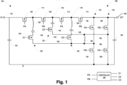
- the converter 100 includes an input terminal 102, an output terminal 104, a first switch 106 connected to a second switch 108 at a node 110, a third switch 112 connected to a fourth switch 114 at a node 116, a first leg 120 connected to the node 110, a flying leg 122 connected to an intermediate node 124 between the second switch 108 and the third switch 112, a second leg 126 connected to the node 116, a rectifier 128 including a first branch 130 and a second branch 132, and a controller 134.
- the first leg 120 includes an inductor 136, a capacitor 138, and an isolation switch 140.
- the flying leg 122 includes a flying capacitor 142 and an isolation switch 144.
- the second leg 126 includes an inductor 146, a capacitor 148, and an isolation switch 150.
- the first branch 130 of the rectifier 128 includes half bridge switches 152, 154.
- the second branch 132 of the rectifier 128 includes half bridge switches 156, 158.
- a compensation inductor 160 is connected between the first branch 130 and the second branch 132.
- An input capacitor 162 may be connected to the input terminal 102 and an output capacitor 164 may be connected to the output terminal 104.
- the converter 100 may be a soft-switching LC resonant converter. It is to be appreciated that while half bride and/or the like is referenced here, this disclosure (including the scope of the claims) is not to be so limited as configurations, arrangements, etc. other than half bride and/or the like are contemplated.
- the inductors 136, 146 are not additional circuit elements, but rather are representative of parasitic inductances within power loops of the converter 100.
- a first power loop comprises the first switch 106, the first leg 120, the active rectifier half bridge switch 152, 154, and traces connecting the first switch 106, the first leg 120, and the rectifier half bridge switch 152, 154.
- a second power loop comprises the second switch 108, the second leg 126, the active rectifier half bridge switch 152, 154, and traces connecting the second switch 108, the second leg 126, and the rectifier half bridge switch 152, 154.
- the converter 100 decreases a voltage provided at the input terminal 102 by a configurable gain, such as from a gain of 4:1 to a gain of 1:1.
- the decreased voltage is provided at the output terminal 104.
- a positive gain may be implemented to increase the voltage at the output terminal 104 relative to the voltage at the input terminal 102.
- the converter can be bidirectional so that step down and/or step up ratios are possible.
- the controller 134 generates signals for controlling the converter 100, such as a pulse width modulated (PWM) signal, PA, a PWM signal, PB, that is out of phase with PA, and isolation signals C1, C2, and C3 for controlling the isolation switches 140, 144, 150, respectively.
- the voltage at the output terminal 104 may be an intermediate voltage, within a system, that may be subsequently stepped down to service a load.
- the rectifier 128 provides a rectified voltage to the output terminal 104 and the output capacitor 164.
- the branches of the rectifier 128 have a half-bridge rectifier topology.
- the half bridge switches 152, 154 of the first branch 130 are connected at a node 166, and the half bridge switches 156, 158 of the second branch 132 are connected at another node 168.
- the compensation inductor 160 couples the first leg 120 to the flying leg 122 (also coupling the first branch 130 to the second branch 132 at the respective switching nodes 166, 168).
- the compensation inductor 160 provides a conduction path that serves to transfer charge to or from the capacitances of the switches 106, 108, 112, 114 such that the voltage across these switches, e.g., the drain-to-source voltage for a field effect transistor (FET), is reduced to zero before a given switch is turned on. In this way, the compensation inductor 160 enables zero voltage switching (ZVS) for each of the switches 106, 108, 112, 114, regardless of whether the legs 120, 126 are matched to a switching frequency of the converter 100. In some embodiments, the compensation inductor 160 is omitted.
- the first leg 120 couples the node 110 to the node 166 of the first branch 130.
- the second leg 126 similarly couples the node 116 to the node 166 of the first branch 130.
- the number of branches in the rectifier 128 may vary.
- the flying leg 122 couples the node 124 to the second branch 132 at the node 168.
- the flying leg 122 may also include a parasitic inductance (not shown).
- the switches 106, 108, 112, 114, 140, 144, 150, 152, 154, 156, 158 in the converter 100 are power metal-oxide semiconductor field-effect transistors (MOSFETs), but other switch types may be used.
- MOSFETs power metal-oxide semiconductor field-effect transistors
- JFETs junction field-effect transistors
- BJTs bipolar junction transistors
- IGBTs insulated gate bipolar transistors
- HEMTs high electron mobility transistors
- GaN gallium nitride
- the switches 106, 108, 112, 114, 140, 144, 150, 152, 154, 156, 158 may be integrated on the same semiconductor die, may each be provided on separate dies, or may otherwise be spread across a plurality of semiconductor dies.
- Each of the switches 106, 108, 112, 114, 140, 144, 150, 152, 154, 156, 158 has drain and source terminals, as well as a gate terminal that controls conduction between the drain and source.
- the controller 134 alternates between setting the first switch 106 to conduct while the second switch 108 is off, and setting the second switch 108 to conduct while the first switch 106 is off. Similarly, the controller alternates the switching of the switches 112, 114.
- the half bridge switches 152, 154 in the first branch 130 of the rectifier 128 and the half bridge switches 156, 158 in the second branch 132 of the rectifier 128 are also alternated.
- the switches 106, 112, 152, 158 are partitioned into a group A which may all be switched together, and the switches 108, 114, 154, 156 are partitioned into a group B which may likewise be switched together.
- the controller 134 generates the PA and PB PWM signals to control the groups. In some embodiments, the controller 134 generates separate control signals for each of the switches 106, 108, 112, 114, 152, 154, 156, 158 rather than providing common control signals for the two switch groups.
- Waveforms for the PA and PB signals are symmetric, i.e., have the same positive pulse intervals, such that each control signal PA, PB, has a duty cycle of approximately 50%.
- the controller 134 generates the control signals PA, PB at a switching frequency, FSW.
- FSW switching frequency
- the controller 134 may be implemented using a combination of analog hardware components (such as transistors, amplifiers, diodes, and resistors), and processor circuitry that includes primarily digital components.
- the processor circuitry may include one or more of a digital signal processor (DSP), a general-purpose processor, and an application-specific integrated circuit (ASIC).
- DSP digital signal processor
- ASIC application-specific integrated circuit
- the controller 134 may also include memory, e.g., non-volatile memory such as flash, that includes instructions or data for use by the processor circuitry, and one or more timers, e.g., for providing the switch intervals according to the switching frequency and dead time intervals.
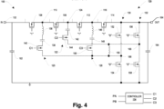
- Figs. 1-4 are schematic diagrams of the converter 100 configured with different gains, according to some embodiments.
- the gain of the converter may be dynamically controlled by the controller 134, based on user input, system requirements, load requirements, or some other consideration.
- the gain between the voltage at the input terminal 102 and the voltage at the output terminal 104 is 4:1, due to the four switches 106, 108, 112, 114 in series.
- the isolation switches 140, 144, 150 are closed by the controller 134 by asserting the control signals C1, C2, C3.
- Other conversion ratios such as 5:1, 6:1, or any other ratio, may be provided by adding additional resonant legs, and such is contemplated herein.
- the converter 100 is configured to have a gain of 3:1.
- the controller 134 opens the isolation switch 150 by de-asserting C3 ( logic "0") to remove the leg 126 from the converter 100 and provides a logic "1" signal to the switch 114, causing the switch 114 to stay closed instead of switching according to the PB signal.
- This always-on condition is represented as a short across the switch 114.
- the converter 100 is configured to have a gain of 2:1.
- the controller 134 opens the isolation switch 150 by de-asserting C3 to remove the leg 126 from the converter 100 and opens the isolation switch 144 by de-asserting C2 to remove the flying leg 122 and the compensation inductor 160 from the converter 100.
- the controller 134 provides a logic "1" signal to the switch 112 and the switch 114, causing the switches 112, 114 to stay closed instead of switching according to the PA and PB signals, respectively. This always-on condition is represented as shorts across the switches 112, 114. Since the flying leg 122 is isolated, the controller 134 opens the half bridge switches 156, 158 in the second branch 132 of the rectifier 128.
- the converter 100 is configured to have a gain of 1:1.
- the controller 134 opens the isolation switch 150 by de-asserting C3 to remove the leg 126 from the converter 100, opens the isolation switch 144 by de-asserting C2 to remove the flying leg 122 and the compensation inductor 160 from the converter 100, and opens the isolation switch 140 by de-asserting C1.
- the controller 134 provides a logic "1" signal to the switches 106, 108, 112, 114, causing the switches 106, 108, 112, 114 to stay closed instead of switching according to the PA and PB signals, respectively. This always-on condition is represented as shorts across the switches 106, 108, 112, 114.
- the controller 134 opens the half bridge switches 152, 154, 156, 158 in the rectifier 128.
- Some of the disclosed techniques may be readily implemented in software using object or object-oriented software development environments that provide portable source code that can be used on a variety of computer or workstation platforms.
- the disclosed techniques and/or arrangements may be implemented partially or fully in hardware using standard logic circuits or VLSI design.
- the disclosed procedures may be readily implemented in software that can be stored on a computer-readable storage medium (such as a memory storage device), executed on programmed general-purpose computer with the cooperation of a controller and memory, a special purpose computer, a microprocessor, or the like.
- a computer-readable storage medium such as a memory storage device
- the arrangements and procedures of the described implementations may be implemented as program embedded on personal computer such as an applet, JAVA ® or CGI script, as a resource residing on a server or computer workstation, as a routine embedded in a dedicated communication arrangement or arrangement component, or the like.
- the arrangements may also be implemented by physically incorporating the arrangements and/or procedures into a software and/or hardware system, such as the hardware and software systems of a test/modeling device.
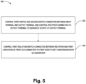
- a flow diagram of a method 500 for controlling a converter 100 is provided, according to some embodiments.
- a first switch 106 and a second switch 108 connected in series at a first node 110 and connected between an input terminal 102 and an output terminal 104 and a rectifier 128 connected to the output terminal 104 are controlled to generate an output at the output terminal 104.
- a first isolation switch 140 connected between the rectifier 128 and a first capacitor 138 of a first leg 120 connected to the first node 110 is controlled to set a conversion ratio of the converter 100. The output is a function of the conversion ratio.
- Fig. 6 illustrates an exemplary embodiment 600 of a computer-readable medium 602, according to some embodiments.
- One or more embodiments involve a computer-readable medium comprising processor-executable instructions configured to implement one or more of the techniques presented herein.
- the embodiment 600 comprises a non-transitory computer-readable medium 602 (e.g., a CD-R, DVD-R, flash drive, a platter of a hard disk drive, etc.), on which is encoded computer-readable data 604.
- a non-transitory computer-readable medium 602 e.g., a CD-R, DVD-R, flash drive, a platter of a hard disk drive, etc.
- This computer-readable data 604 in turn comprises a set of processor-executable computer instructions 606 that, when executed by a computing device 608 including a reader 610 for reading the processor-executable computer instructions 606 and a processor 612 for executing the processor-executable computer instructions 606, are configured to facilitate operations according to one or more of the principles set forth herein.
- the processor-executable computer instructions 606, when executed, are configured to facilitate performance of a method 614, such as at least some of the aforementioned method(s).
- the processor-executable computer instructions 606, when executed, are configured to facilitate implementation of a system, such as at least some of the one or more aforementioned system(s).
- Many such computer-readable media may be devised by those of ordinary skill in the art that are configured to operate in accordance with the techniques presented herein.
- Computer readable media may include communication media.
- Communication media typically embodies computer readable instructions or other data in a “modulated data signal” such as a carrier wafer or other transport mechanism and includes any information delivery media.
- modulated data signal may include a signal that has one or more of its characteristics set or changed in such a manner as to encode information in the signal.
- the converter 100 with the capability of dynamically changing the gain allows the converter 100 to be used in a wide variety of applications.
- a higher voltage allows faster charging without increasing current.
- Slower charging may be provided using a different gain, for example during the latter portion of the charging cycle, or for charging devices not compatible with fast charging.
- the charging voltage may be changed by configuring the gain to maintain peak power performance.
- the converter 100 facilitates omission of a transformer or inductor on the output to scale the voltage, thereby reducing the system footprint and cost.
- a converter comprises an input terminal, an output terminal, a rectifier connected between the input terminal and the output terminal, a first switch, a second switch connected to the output terminal and connected in series with the first switch at a first node, and a first leg comprising a first capacitor coupled to the first node, and a first isolation switch connected between the first capacitor and the rectifier.
- the converter comprises a controller configured to control the first switch and the second switch to generate an output at the output terminal according to a first conversion ratio, wherein the controller is configured to control the first isolation switch to generate the output according to a second conversion ratio different than the first conversion ratio.
- the first leg has a first inductance
- a capacitance of the first capacitor is determined such that a switch frequency used by the controller to control the first switch and the second switch is a resonant frequency of the first capacitor and the first inductance
- the first inductance comprises parasitic inductances within a first power loop connecting the input terminal to the output terminal
- the first power loop comprises the first switch, the first leg, a rectifier switch in the rectifier, and traces connecting the first switch, the first leg, and the rectifier switch.
- the converter comprises a third switch connected to the output terminal and connected in series with the second switch at a second node, and a second leg comprises a second capacitor coupled to the second node, and a second isolation switch connected between the second capacitor and the rectifier.
- the first isolation switch connects the first leg to a first branch of the rectifier, and the second isolation switch connects the second leg to a second branch of the rectifier.
- the converter comprises a compensation inductor connected between the first leg and the second leg.
- the converter comprises a third switch connected in series with the second switch at a second node, a flying leg comprises a flying capacitor coupled to the second node, and a second isolation switch connected between the flying capacitor and the rectifier, a fourth switch connected to the output terminal and connected in series with the third switch at a third node, and a second leg comprises a second capacitor coupled to the third node, and a third isolation switch connected between the second capacitor and the rectifier.
- the first isolation switch connects the first leg to a first branch of the rectifier
- the second isolation switch connects the flying leg to a second branch of the rectifier
- the third isolation switch connects the second leg to the first branch of the rectifier
- the converter comprises a compensation inductor connected between the first leg and the second leg.
- a converter comprises an input terminal, an output terminal, a rectifier connected between the input terminal and the output terminal, a first switch, a second switch connected to the output terminal and connected in series with the first switch at a first node, a first resonant leg comprising a first resonant capacitor coupled to the first node and a first isolation switch connected between the first resonant capacitor and a first branch of the rectifier, a third switch connected to the output terminal and connected in series with the second switch at a second node, a flying leg comprising a flying capacitor coupled to the second node and a second isolation switch connected between the flying capacitor and a second branch of the rectifier, a compensation inductor connected between the first resonant leg and the flying leg, and a controller configured to control the first switch, the second switch, the third switch, and the rectifier to generate an output at the output terminal, wherein the controller is configured to control at least one of the first switch, the second switch, the third switch, the first isolation switch, or the second
- the controller is configured to close the first isolation switch and the second isolation switch to set the conversion ratio to 3:1, the controller is configured to close the first isolation switch, open the second isolation switch, and close the third switch to set the conversion ratio to 2:1, and the controller is configured to open the first isolation switch and the second isolation switch, and close the first switch, the second switch, and the third switch to set the conversion ratio to 1:1.
- the converter comprises a fourth switch connected to the output terminal and connected in series with the third switch at a third node and a second resonant leg comprises a second resonant capacitor coupled to the third node and a third isolation switch connected between the second resonant capacitor and the first branch of the rectifier, wherein the controller is configured to control the first switch, the second switch, the third switch, the fourth switch, and the rectifier to generate the output at the output terminal, and the controller is configured to control at least one of the first switch, the second switch, the third switch, the fourth switch, the first isolation switch, the second isolation switch, or the third isolation switch to set the conversion ratio of the converter.
- the controller is configured to close the first isolation switch, the second isolation switch, and the third isolation switch to set the conversion ratio to 4:1, the controller is configured to close the first isolation switch and the second isolation switch, open the third isolation switch, and close the fourth switch to set the conversion ratio to 3:1, the controller is configured to close the first isolation switch, open the second isolation switch and the third isolation switch, and close the third switch and the fourth switch to set the conversion ratio to 2:1, and the controller is configured to open the first isolation switch, the second isolation switch, and the third isolation switch, and close the first switch, the second switch, the third switch, and the fourth switch to set the conversion ratio to 1:1.
- a method of controlling a converter comprises controlling a first switch and a second switch connected in series at a first node and connected between an input terminal and an output terminal and controlling a rectifier connected to the output terminal to generate an output at the output terminal and controlling a first isolation switch connected between the rectifier and a first capacitor of a first leg connected to the first node to set a conversion ratio of the converter, wherein the output is a function of the conversion ratio.
- the method comprises controlling the first switch, the second switch, and a third switch connected in series with the second switch at a second node to generate the output at the output terminal and controlling the first isolation switch and a second isolation switch connected between the rectifier and a second capacitor of a second leg connected to the second node to set the conversion ratio of the converter.
- controlling the first isolation switch comprises controlling the first isolation switch to connect the first leg to a first branch of the rectifier that is connected to a compensation inductor and controlling the second isolation switch comprises controlling the second isolation switch to connect the second leg to a second branch of the rectifier that is connected to the compensation inductor.
- the method comprises closing the first isolation switch and the second isolation switch to set the conversion ratio to 3:1, closing the first isolation switch, opening the second isolation switch, and closing the third switch to set the conversion ratio to 2:1, and opening the first isolation switch and the second isolation switch, and closing the first switch, the second switch, and the third switch to set the conversion ratio to 1:1.
- the method comprises controlling the first switch, the second switch, the third switch, and a fourth switch connected in series with the third switch at a third node to generate the output at the output terminal and controlling the first isolation switch, the second isolation switch, and a third isolation switch connected between the rectifier and a third capacitor of a third leg connected to the third node to set the conversion ratio of the converter.
- the method comprises closing the first isolation switch, the second isolation switch, and the third isolation switch to set the conversion ratio to 4:1, closing the first isolation switch and the second isolation switch, opening the third isolation switch, and closing the fourth switch to set the conversion ratio to 3:1, closing the first isolation switch, opening the second isolation switch and the third isolation switch, and closing the third switch and the fourth switch to set the conversion ratio to 2:1, and opening the first isolation switch, the second isolation switch, and the third isolation switch, and closing the first switch, the second switch, the third switch, and the fourth switch to set the conversion ratio to 1:1.
- controlling the first isolation switch comprises controlling the first isolation switch to connect the first leg to a first branch of the rectifier that is connected to a compensation inductor
- controlling the second isolation switch comprises controlling the second isolation switch to connect the second leg to a second branch of the rectifier that is connected to the compensation inductor
- controlling the third isolation switch comprises controlling the third isolation switch to connect the third leg to the first branch of the rectifier.
- exemplary is used herein to mean serving as an example, instance, illustration, etc., and not necessarily as advantageous.
- “or” is intended to mean an inclusive “or” rather than an exclusive “or”.
- “a” and “an” as used in this application and the appended claims are generally to be construed to mean “one or more” unless specified otherwise or clear from context to be directed to a singular form.
- at least one of A and B and/or the like generally means A or B or both A and B.
- such terms are intended to be inclusive in a manner similar to the term “comprising”.
- first,” “second,” or the like are not intended to imply a temporal aspect, a spatial aspect, an ordering, etc. Rather, such terms are merely used as identifiers, names, etc. for features, elements, items, etc.
- a first element and a second element generally correspond to element A and element B or two different or two identical elements or the same element.
- Embodiment 1 is a converter, comprising: an input terminal; an output terminal; a rectifier connected between the input terminal and the output terminal; a first switch; a second switch connected to the output terminal and connected in series with the first switch at a first node; and a first leg comprising: a first capacitor coupled to the first node; and a first isolation switch connected between the first capacitor and the rectifier.
- the converter of embodiment 1 comprises: a controller configured to control the first switch and the second switch to generate an output at the output terminal according to a first conversion ratio, wherein: the controller is configured to control the first isolation switch to generate the output according to a second conversion ratio different than the first conversion ratio.
- the first leg has a first inductance; a capacitance of the first capacitor is determined such that a switch frequency used by the controller to control the first switch and the second switch is a resonant frequency of the first capacitor and the first inductance; the first inductance comprises parasitic inductances within a first power loop connecting the input terminal to the output terminal; and the first power loop comprises the first switch, the first leg, a rectifier switch in the rectifier, and traces connecting the first switch, the first leg, and the rectifier switch.
- the converter of any of the preceding embodiments comprises: a third switch connected to the output terminal and connected in series with the second switch at a second node; and a second leg comprising: a second capacitor coupled to the second node; and a second isolation switch connected between the second capacitor and the rectifier.
- the first isolation switch connects the first leg to a first branch of the rectifier; and the second isolation switch connects the second leg to a second branch of the rectifier.
- the converter of embodiment 4 or 5 comprises: a compensation inductor connected between the first leg and the second leg.
- the converter of any of the preceding embodiments comprises: a third switch connected in series with the second switch at a second node; a flying leg comprising: a flying capacitor coupled to the second node; and a second isolation switch connected between the flying capacitor and the rectifier; a fourth switch connected to the output terminal and connected in series with the third switch at a third node; and a second leg comprising: a second capacitor coupled to the third node; and a third isolation switch connected between the second capacitor and the rectifier.
- the first isolation switch connects the first leg to a first branch of the rectifier; the second isolation switch connects the flying leg to a second branch of the rectifier; and the third isolation switch connects the second leg to the first branch of the rectifier.
- the converter of embodiment 7 or 8 comprises: a compensation inductor connected between the first leg and the second leg.
- Embodiment 10 is a converter, comprising: an input terminal; an output terminal; a rectifier connected between the input terminal and the output terminal; a first switch; a second switch connected to the output terminal and connected in series with the first switch at a first node; a first resonant leg comprising: a first resonant capacitor coupled to the first node; and a first isolation switch connected between the first resonant capacitor and a first branch of the rectifier; a third switch connected to the output terminal and connected in series with the second switch at a second node; a flying leg comprising: a flying capacitor coupled to the second node; and a second isolation switch connected between the flying capacitor and a second branch of the rectifier; a compensation inductor connected between the first resonant leg and the flying leg; and a controller configured to control the first switch, the second switch, the third switch, and the rectifier to generate an output at the output terminal, wherein: the controller is configured to control at least one of the first switch, the second switch, the third switch
- the controller is configured to close the first isolation switch and the second isolation switch to set the conversion ratio to 3:1; the controller is configured to close the first isolation switch, open the second isolation switch, and close the third switch to set the conversion ratio to 2:1; and the controller is configured to open the first isolation switch and the second isolation switch, and close the first switch, the second switch, and the third switch to set the conversion ratio to 1:1.
- the converter of embodiment 11 comprises: a fourth switch connected to the output terminal and connected in series with the third switch at a third node; and a second resonant leg comprising: a second resonant capacitor coupled to the third node; and a third isolation switch connected between the second resonant capacitor and the first branch of the rectifier; wherein: the controller is configured to control the first switch, the second switch, the third switch, the fourth switch, and the rectifier to generate the output at the output terminal; and the controller is configured to control at least one of the first switch, the second switch, the third switch, the fourth switch, the first isolation switch, the second isolation switch, or the third isolation switch to set the conversion ratio of the converter.
- the controller is configured to close the first isolation switch, the second isolation switch, and the third isolation switch to set the conversion ratio to 4:1; the controller is configured to close the first isolation switch and the second isolation switch, open the third isolation switch, and close the fourth switch to set the conversion ratio to 3:1; the controller is configured to close the first isolation switch, open the second isolation switch and the third isolation switch, and close the third switch and the fourth switch to set the conversion ratio to 2:1; and the controller is configured to open the first isolation switch, the second isolation switch, and the third isolation switch, and close the first switch, the second switch, the third switch, and the fourth switch to set the conversion ratio to 1:1.
- Embodiment 14 is a method of controlling a converter, comprising: controlling a first switch and a second switch connected in series at a first node and connected between an input terminal and an output terminal and controlling a rectifier connected to the output terminal to generate an output at the output terminal; and controlling a first isolation switch connected between the rectifier and a first capacitor of a first leg connected to the first node to set a conversion ratio of the converter, wherein the output is a function of the conversion ratio.
- the method of embodiment 14 comprises: controlling the first switch, the second switch, and a third switch connected in series with the second switch at a second node to generate the output at the output terminal; and controlling the first isolation switch and a second isolation switch connected between the rectifier and a second capacitor of a second leg connected to the second node to set the conversion ratio of the converter.
- controlling the first isolation switch comprises controlling the first isolation switch to connect the first leg to a first branch of the rectifier that is connected to a compensation inductor; and controlling the second isolation switch comprises controlling the second isolation switch to connect the second leg to a second branch of the rectifier that is connected to the compensation inductor.
- the method of embodiment 16 comprises: closing the first isolation switch and the second isolation switch to set the conversion ratio to 3:1; closing the first isolation switch, opening the second isolation switch, and closing the third switch to set the conversion ratio to 2:1; and opening the first isolation switch and the second isolation switch, and closing the first switch, the second switch, and the third switch to set the conversion ratio to 1:1.
- the method of one of embodiments 15-17 comprises: controlling the first switch, the second switch, the third switch, and a fourth switch connected in series with the third switch at a third node to generate the output at the output terminal; and controlling the first isolation switch, the second isolation switch, and a third isolation switch connected between the rectifier and a third capacitor of a third leg connected to the third node to set the conversion ratio of the converter.
- the method of embodiment 18 comprises: closing the first isolation switch, the second isolation switch, and the third isolation switch to set the conversion ratio to 4:1; closing the first isolation switch and the second isolation switch, opening the third isolation switch, and closing the fourth switch to set the conversion ratio to 3:1; closing the first isolation switch, opening the second isolation switch and the third isolation switch, and closing the third switch and the fourth switch to set the conversion ratio to 2:1; and opening the first isolation switch, the second isolation switch, and the third isolation switch, and closing the first switch, the second switch, the third switch, and the fourth switch to set the conversion ratio to 1:1.
- controlling the first isolation switch comprises controlling the first isolation switch to connect the first leg to a first branch of the rectifier that is connected to a compensation inductor; controlling the second isolation switch comprises controlling the second isolation switch to connect the second leg to a second branch of the rectifier that is connected to the compensation inductor; and controlling the third isolation switch comprises controlling the third isolation switch to connect the third leg to the first branch of the rectifier.
Landscapes
- Engineering & Computer Science (AREA)
- Power Engineering (AREA)
- Dc-Dc Converters (AREA)
Applications Claiming Priority (1)
| Application Number | Priority Date | Filing Date | Title |
|---|---|---|---|
| US18/099,606 US12614978B2 (en) | 2023-01-20 | 2023-01-20 | Capacitor converter |
Publications (1)
| Publication Number | Publication Date |
|---|---|
| EP4404451A1 true EP4404451A1 (de) | 2024-07-24 |
Family
ID=89662153
Family Applications (1)
| Application Number | Title | Priority Date | Filing Date |
|---|---|---|---|
| EP24152906.4A Pending EP4404451A1 (de) | 2023-01-20 | 2024-01-19 | Kondensatorwandler |
Country Status (3)
| Country | Link |
|---|---|
| US (1) | US12614978B2 (de) |
| EP (1) | EP4404451A1 (de) |
| CN (1) | CN118381318A (de) |
Citations (2)
| Publication number | Priority date | Publication date | Assignee | Title |
|---|---|---|---|---|
| CN113746326A (zh) * | 2021-09-07 | 2021-12-03 | 上海伏达半导体有限公司 | 一种开关电容转换器及方法 |
| EP3940941A1 (de) * | 2020-07-13 | 2022-01-19 | Delta Electronics (Shanghai) Co., Ltd. | Umwandlungsschaltungstopologie |
Family Cites Families (2)
| Publication number | Priority date | Publication date | Assignee | Title |
|---|---|---|---|---|
| US10224803B1 (en) | 2017-12-20 | 2019-03-05 | Infineon Technologies Austria Ag | Switched capacitor converter with compensation inductor |
| US11936290B2 (en) * | 2021-11-01 | 2024-03-19 | Halo Microelectronics International | Switched capacitor converter and control method |
-
2023
- 2023-01-20 US US18/099,606 patent/US12614978B2/en active Active
-
2024
- 2024-01-18 CN CN202410074362.9A patent/CN118381318A/zh active Pending
- 2024-01-19 EP EP24152906.4A patent/EP4404451A1/de active Pending
Patent Citations (2)
| Publication number | Priority date | Publication date | Assignee | Title |
|---|---|---|---|---|
| EP3940941A1 (de) * | 2020-07-13 | 2022-01-19 | Delta Electronics (Shanghai) Co., Ltd. | Umwandlungsschaltungstopologie |
| CN113746326A (zh) * | 2021-09-07 | 2021-12-03 | 上海伏达半导体有限公司 | 一种开关电容转换器及方法 |
Also Published As
| Publication number | Publication date |
|---|---|
| CN118381318A (zh) | 2024-07-23 |
| US12614978B2 (en) | 2026-04-28 |
| US20240250608A1 (en) | 2024-07-25 |
Similar Documents
| Publication | Publication Date | Title |
|---|---|---|
| US11750101B2 (en) | Resonant converter | |
| CN108123605B (zh) | 电源变换电路的控制方法以及相关电源变换电路 | |
| CN105684287B (zh) | 用于谐振转换器的栅驱动装置 | |
| US9923466B2 (en) | DC-DC converter with inductor current direction reversed each switching period | |
| JP2005501497A (ja) | Dc−dc変換器内の損失を小さくする方法と回路 | |
| WO2017049179A1 (en) | Converters with hold-up operation | |
| CN111726005A (zh) | 相移全桥转换器、操作相移全桥转换器的方法和ac/dc转换器 | |
| CN107404228A (zh) | 一种新颖的宽范围输入功率变换电路 | |
| TW201739169A (zh) | 切換放大器及功率轉換器 | |
| Barner et al. | A 10 MHz, 48-to-5V synchronous converter with dead time enabled 125 ps resolution zero-voltage switching | |
| US11973440B2 (en) | Isolated DC/DC converter with secondary-side full bridge diode rectifier and asymmetrical auxiliary capacitor | |
| US10348205B1 (en) | Coupled-inductor cascaded buck converter with fast transient response | |
| JP7637428B2 (ja) | 直接電力変換器 | |
| US6567284B2 (en) | DC to DC converting incorporating ZVS circuit and synchronized isolation circuit | |
| CN112087143A (zh) | 一种多端输入单端输出的准并联谐振变换器 | |
| US12614978B2 (en) | Capacitor converter | |
| TW202241032A (zh) | 藉雙重切換達到軟性切換之切換式電源電路及其控制電路 | |
| US7548442B2 (en) | Power converter with coupled inductor | |
| TW202008705A (zh) | 輸入電流漣波互補電路及包含其之昇壓轉換器 | |
| CN116207987A (zh) | 降压电路、降压电路控制方法、装置及系统 | |
| CN112564477A (zh) | 一种具有强降压能力的转换电路 | |
| Peng et al. | 100 MHz, 85% efficient integrated AlGaAs/GaAs supply modulator for RF power amplifier modules | |
| CN214154336U (zh) | 一种基于Buck电路DC-DC强降压转换电路 | |
| US20250300564A1 (en) | Power converter | |
| US9018926B1 (en) | Soft-switched PFC converter |
Legal Events
| Date | Code | Title | Description |
|---|---|---|---|
| PUAI | Public reference made under article 153(3) epc to a published international application that has entered the european phase |
Free format text: ORIGINAL CODE: 0009012 |
|
| STAA | Information on the status of an ep patent application or granted ep patent |
Free format text: STATUS: THE APPLICATION HAS BEEN PUBLISHED |
|
| AK | Designated contracting states |
Kind code of ref document: A1 Designated state(s): AL AT BE BG CH CY CZ DE DK EE ES FI FR GB GR HR HU IE IS IT LI LT LU LV MC ME MK MT NL NO PL PT RO RS SE SI SK SM TR |
|
| STAA | Information on the status of an ep patent application or granted ep patent |
Free format text: STATUS: REQUEST FOR EXAMINATION WAS MADE |
|
| 17P | Request for examination filed |
Effective date: 20250121 |