EP4404370A1 - Busbar assembly capable of preventing damage due to occurrence of fire and battery pack comprising same - Google Patents
Busbar assembly capable of preventing damage due to occurrence of fire and battery pack comprising same Download PDFInfo
- Publication number
- EP4404370A1 EP4404370A1 EP23875100.2A EP23875100A EP4404370A1 EP 4404370 A1 EP4404370 A1 EP 4404370A1 EP 23875100 A EP23875100 A EP 23875100A EP 4404370 A1 EP4404370 A1 EP 4404370A1
- Authority
- EP
- European Patent Office
- Prior art keywords
- busbar
- assembly according
- busbar assembly
- cover member
- protrusion
- Prior art date
- Legal status (The legal status is an assumption and is not a legal conclusion. Google has not performed a legal analysis and makes no representation as to the accuracy of the status listed.)
- Pending
Links
Images


Classifications
-
- H—ELECTRICITY
- H01—ELECTRIC ELEMENTS
- H01M—PROCESSES OR MEANS, e.g. BATTERIES, FOR THE DIRECT CONVERSION OF CHEMICAL ENERGY INTO ELECTRICAL ENERGY
- H01M50/00—Constructional details or processes of manufacture of the non-active parts of electrochemical cells other than fuel cells, e.g. hybrid cells
- H01M50/50—Current conducting connections for cells or batteries
- H01M50/502—Interconnectors for connecting terminals of adjacent batteries; Interconnectors for connecting cells outside a battery casing
- H01M50/507—Interconnectors for connecting terminals of adjacent batteries; Interconnectors for connecting cells outside a battery casing comprising an arrangement of two or more busbars within a container structure, e.g. busbar modules
-
- H—ELECTRICITY
- H01—ELECTRIC ELEMENTS
- H01M—PROCESSES OR MEANS, e.g. BATTERIES, FOR THE DIRECT CONVERSION OF CHEMICAL ENERGY INTO ELECTRICAL ENERGY
- H01M50/00—Constructional details or processes of manufacture of the non-active parts of electrochemical cells other than fuel cells, e.g. hybrid cells
- H01M50/20—Mountings; Secondary casings or frames; Racks, modules or packs; Suspension devices; Shock absorbers; Transport or carrying devices; Holders
- H01M50/204—Racks, modules or packs for multiple batteries or multiple cells
-
- H—ELECTRICITY
- H01—ELECTRIC ELEMENTS
- H01M—PROCESSES OR MEANS, e.g. BATTERIES, FOR THE DIRECT CONVERSION OF CHEMICAL ENERGY INTO ELECTRICAL ENERGY
- H01M50/00—Constructional details or processes of manufacture of the non-active parts of electrochemical cells other than fuel cells, e.g. hybrid cells
- H01M50/50—Current conducting connections for cells or batteries
- H01M50/502—Interconnectors for connecting terminals of adjacent batteries; Interconnectors for connecting cells outside a battery casing
- H01M50/503—Interconnectors for connecting terminals of adjacent batteries; Interconnectors for connecting cells outside a battery casing characterised by the shape of the interconnectors
-
- H—ELECTRICITY
- H01—ELECTRIC ELEMENTS
- H01M—PROCESSES OR MEANS, e.g. BATTERIES, FOR THE DIRECT CONVERSION OF CHEMICAL ENERGY INTO ELECTRICAL ENERGY
- H01M50/00—Constructional details or processes of manufacture of the non-active parts of electrochemical cells other than fuel cells, e.g. hybrid cells
- H01M50/50—Current conducting connections for cells or batteries
- H01M50/502—Interconnectors for connecting terminals of adjacent batteries; Interconnectors for connecting cells outside a battery casing
- H01M50/521—Interconnectors for connecting terminals of adjacent batteries; Interconnectors for connecting cells outside a battery casing characterised by the material
- H01M50/522—Inorganic material
-
- H—ELECTRICITY
- H01—ELECTRIC ELEMENTS
- H01M—PROCESSES OR MEANS, e.g. BATTERIES, FOR THE DIRECT CONVERSION OF CHEMICAL ENERGY INTO ELECTRICAL ENERGY
- H01M50/00—Constructional details or processes of manufacture of the non-active parts of electrochemical cells other than fuel cells, e.g. hybrid cells
- H01M50/50—Current conducting connections for cells or batteries
- H01M50/502—Interconnectors for connecting terminals of adjacent batteries; Interconnectors for connecting cells outside a battery casing
- H01M50/521—Interconnectors for connecting terminals of adjacent batteries; Interconnectors for connecting cells outside a battery casing characterised by the material
- H01M50/526—Interconnectors for connecting terminals of adjacent batteries; Interconnectors for connecting cells outside a battery casing characterised by the material having a layered structure
-
- H—ELECTRICITY
- H01—ELECTRIC ELEMENTS
- H01M—PROCESSES OR MEANS, e.g. BATTERIES, FOR THE DIRECT CONVERSION OF CHEMICAL ENERGY INTO ELECTRICAL ENERGY
- H01M50/00—Constructional details or processes of manufacture of the non-active parts of electrochemical cells other than fuel cells, e.g. hybrid cells
- H01M50/50—Current conducting connections for cells or batteries
- H01M50/572—Means for preventing undesired use or discharge
- H01M50/584—Means for preventing undesired use or discharge for preventing incorrect connections inside or outside the batteries
- H01M50/588—Means for preventing undesired use or discharge for preventing incorrect connections inside or outside the batteries outside the batteries, e.g. incorrect connections of terminals or busbars
-
- H—ELECTRICITY
- H01—ELECTRIC ELEMENTS
- H01M—PROCESSES OR MEANS, e.g. BATTERIES, FOR THE DIRECT CONVERSION OF CHEMICAL ENERGY INTO ELECTRICAL ENERGY
- H01M50/00—Constructional details or processes of manufacture of the non-active parts of electrochemical cells other than fuel cells, e.g. hybrid cells
- H01M50/50—Current conducting connections for cells or batteries
- H01M50/572—Means for preventing undesired use or discharge
- H01M50/584—Means for preventing undesired use or discharge for preventing incorrect connections inside or outside the batteries
- H01M50/59—Means for preventing undesired use or discharge for preventing incorrect connections inside or outside the batteries characterised by the protection means
- H01M50/591—Covers
-
- H—ELECTRICITY
- H01—ELECTRIC ELEMENTS
- H01M—PROCESSES OR MEANS, e.g. BATTERIES, FOR THE DIRECT CONVERSION OF CHEMICAL ENERGY INTO ELECTRICAL ENERGY
- H01M2220/00—Batteries for particular applications
- H01M2220/20—Batteries in motive systems, e.g. vehicle, ship, plane
-
- H—ELECTRICITY
- H01—ELECTRIC ELEMENTS
- H01M—PROCESSES OR MEANS, e.g. BATTERIES, FOR THE DIRECT CONVERSION OF CHEMICAL ENERGY INTO ELECTRICAL ENERGY
- H01M2220/00—Batteries for particular applications
- H01M2220/30—Batteries in portable systems, e.g. mobile phone, laptop
-
- Y—GENERAL TAGGING OF NEW TECHNOLOGICAL DEVELOPMENTS; GENERAL TAGGING OF CROSS-SECTIONAL TECHNOLOGIES SPANNING OVER SEVERAL SECTIONS OF THE IPC; TECHNICAL SUBJECTS COVERED BY FORMER USPC CROSS-REFERENCE ART COLLECTIONS [XRACs] AND DIGESTS
- Y02—TECHNOLOGIES OR APPLICATIONS FOR MITIGATION OR ADAPTATION AGAINST CLIMATE CHANGE
- Y02E—REDUCTION OF GREENHOUSE GAS [GHG] EMISSIONS, RELATED TO ENERGY GENERATION, TRANSMISSION OR DISTRIBUTION
- Y02E60/00—Enabling technologies; Technologies with a potential or indirect contribution to GHG emissions mitigation
- Y02E60/10—Energy storage using batteries
Definitions
- the present invention relates to a busbar assembly capable of preventing damage by fire and a battery pack including the same, and more particularly to a busbar assembly capable of preventing fire in a battery cell received in one of a plurality of battery modules from spreading to a battery module adjacent thereto in a direction toward a busbar assembly, thereby preventing damage by fire, and a battery pack including the same.
- Secondary batteries which are capable of being charged and discharged, are intimately used in daily life.
- secondary batteries are used in mobile devices, electric vehicles, and hybrid electric vehicles.
- fire may break out in a battery cell received in a battery module due to external impact, short circuit, overcurrent, etc., and such fire may cause secondary damage along a busbar that connects adjacent battery modules to each other.
- FIG. 1 is a perspective view showing a conventional flexible busbar assembly.
- the conventional flexible busbar assembly includes a busbar 10 configured to electrically connect adjacent battery modules to each other and a cover member 20 configured to wrap the busbar 10.
- a specific part of the conventional flexible busbar assembly may be deformed into a desired shape, for example, by bending in order to easily electrically connect battery modules provided on a complex path to each other.
- the cover member 20 may melt and the exposed busbar 10 may come into contact with a metal adjacent thereto, whereby short circuit may occur.
- fire and venting gas may be transferred to neighboring battery modules via the busbar 10 and the cover member 20, whereby secondary damage, such as fire spread, may occur.
- Patent Document 1 Korean Patent Application Publication No. 2015-0101154
- the present invention has been made in view of the above problems, and it is an object of the present invention to provide a busbar assembly capable of inhibiting short circuit due to contact between a busbar and a metal adjacent thereto as the result of a covering member being lost due to fire, thereby preventing damage by fire, and a battery pack including the same.
- a busbar assembly includes a busbar (100) including a copper material and a cover member (200) wrapping a part of the busbar (100), wherein the busbar (100) includes a first busbar (110) and a second busbar, the first busbar protrudes from each of opposite sides of the cover member (200) and the second busbar (120) is wrapped by the cover member (200), and the width (W2) of the second busbar (120) is less than the width (W1) of the first busbar (110).
- the height (L2) of the second busbar (120) may be less than the height (L1) of the first busbar (110).
- the second busbar (120) may include at least one protrusion provided at an outer surface thereof , wherein the at least one protrusion is spaced apart from the first busbar (110).
- the protrusion (121) may have a quadrangular sectional shape.
- the protrusion (121) may be provided in a plurality, so as to form an uneven shape.
- the protrusion (121) may have a right triangular sectional shape.
- an inclined surface of the right triangular shape is formed to face the middle of the second busbar (120).
- a metal layer (111) having a predetermined thickness may be formed on each of an upper surface and a lower surface of the first busbar (110).
- the metal layer (111) may be formed by copper clad aluminum (CCA) welding.
- the cover member (200) may include a refractory material.
- the refractory material may include at least one of a ceramized silicone, a resin mixed with a polyethylene and an ethylene copolymer, and mica.
- the present invention provides a battery pack including a busbar assembly having the aforementioned features.
- a busbar assembly according to the present invention has an advantage in that a step is formed between a first busbar and a second busbar, whereby it is possible to prevent fire and venting gas from being introduced between the busbar and a cover member.
- the busbar assembly according to the present invention has an advantage in that a protrusion is formed on the second busbar, whereby it is possible to inhibit the movement of the fire and the venting gas introduced between the busbar and the cover member.
- the busbar assembly according to the present invention has an advantage in that the cover member is not lost by fire, whereby it is possible to block contact between the busbar and a metal adjacent thereto, and therefore it is possible to prevent short circuit.
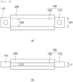
- FIG. 2 is a sectional view of a busbar assembly according to a first preferred embodiment of the present invention, cut in a vertical direction and a horizontal direction.
- the busbar assembly includes a busbar 100 and a cover member 200 configured to wrap a part of the busbar 100.
- the busbar 100 may be made of a flat copper material, and may include a first busbar 110 located at each of opposite ends and a second busbar 120 wrapped by the cover member 200, the second busbar being configured to connect the first busbars 110 located at the opposite ends to each other.
- the first busbar 110 may be connected to a terminal of a battery module adjacent thereto, and the second busbar 120 connects the first busbars 110 located at opposite sides thereof to each other through a wall configured to partition each battery module zone in a case configured to receive a battery module in a state of being wrapped by the cover member 200.
- the width W2 of the second busbar 120 may be less than the width W1 of the first busbar 110, and the height L2 of the second busbar 120 may be less than the height L1 of the first busbar 110, whereby a step may be formed between the first busbar 110 and the second busbar 120.
- the second busbar 120 is wrapped by the cover member 200. Even though fire or venting gas occurs in a direction toward the first busbar 110, therefore, it is difficult for the venting gas to be introduced between the second busbar 120 and the cover member due to the step formed between the first busbar 110 and the second busbar 120, whereby safety may be improved.
- the cover member 200 which wraps the second busbar 120 to prevent short circuit due to contact between the second busbar 120 and a metal adjacent thereto, may be made of an insulative material.
- the cover member 200 may be made of a refractory material that does not melt in the event of fire or at high temperatures.
- the cover member may be made of a material including at least one of ceramized silicone, a ceramic material, a resin mixed with a polyethylene and ethylene copolymer, mica, glass fiber woven fabric, and a mixture of mPPO and GF20.
- the movement of the cover member 200 in a longitudinal direction thereof may be restricted by the step formed between the first busbar 110 and the second busbar 120, whereby fixation force may be improved.
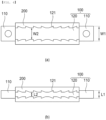
- FIG. 3 is a sectional view of a busbar assembly according to a second preferred embodiment of the present invention, cut in the vertical direction and the horizontal direction.
- the busbar assembly according to the second preferred embodiment of the present invention is identical to the busbar assembly according to the first embodiment described with reference to FIG. 2 except for the shape of a second busbar 120, and therefore a description of the same configuration will be omitted.
- At least one band-shaped protrusion 121 may be formed on an outer surface of the second busbar 120 along the perimeter of the second busbar 120, and the sectional shape of the protrusion 121 may be quadrangular.
- a plurality of protrusions 121 may be provided, and the protrusions may be spaced apart from each other by a predetermined distance to form an uneven shape.
- each protrusion 121 may block venting gas introduced between the second busbar 120 and a cover member 200, whereby the effect of blocking the movement of the venting gas may be improved, compared to when only one protrusion 121 is formed.
- the outermost protrusion 121 may be formed so as to be spaced apart from a first busbar 110.
- the reason for this is that, if the protrusion 121 is formed so as to be in tight contact with the first busbar 110, no step is formed between the first busbar 110 and the second busbar 120, whereby the effect of inhibiting the inflow of venting gas due to the step may be reduced.
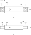
- FIG. 4 is a sectional view of a busbar assembly according to a third preferred embodiment of the present invention, cut in the vertical direction and the horizontal direction.
- the busbar assembly according to the third preferred embodiment of the present invention is identical to the busbar assembly according to the first embodiment described with reference to FIG. 2 except for the shape of a second busbar 120, and therefore a description of the same configuration will be omitted.
- At least one band-shaped protrusion 121 may be formed on an outer surface of the second busbar 120 along the perimeter of the second busbar 120.
- the sectional shape of the protrusion 121 may be right triangular, and an inclined surface of the right triangular shape inclined at a predetermined angle may be formed so as to face the middle of the second busbar 120.
- a plurality of protrusions 121 may be provided so as to be spaced apart from each other. When a plurality of protrusions 121 is formed, each protrusion 121 may block venting gas introduced between the second busbar 120 and a cover member 200, whereby the effect of blocking the movement of the venting gas may be improved, compared to when only one protrusion 121 is formed.
- the outermost protrusion 121 may be formed so as to be spaced apart from a first busbar 110.
- the reason for this is that, if the protrusion 121 is formed so as to be in tight contact with the first busbar 110, no step is formed between the first busbar 110 and the second busbar 120, whereby the effect of inhibiting the inflow of venting gas due to the step may be reduced.
- FIG. 5 is a sectional view of a busbar assembly according to a fourth preferred embodiment of the present invention, cut in the vertical direction and the horizontal direction.
- the busbar assembly according to the fourth preferred embodiment of the present invention is identical to the busbar assembly according to the first embodiment described with reference to FIG. 2 except that a metal layer 111 is formed on a first busbar 110, and therefore a description of the same configuration will be omitted.
- a metal layer 111 having a predetermined thickness may be formed on each of an upper surface and a lower surface of a first busbar 110 located at each of opposite ends.
- the metal layer 111 may be made of aluminum, and may be formed by copper clad aluminum (CCA) welding.
- CCA copper clad aluminum
- a step may be formed between the first busbar 110 and a second busbar 120, whereby it is possible to prevent venting gas from being introduced between the first busbar 120 and a cover member 200.
- the height of the first busbar 110 excluding the metal layer 111 is shown as being greater than the height of the second busbar 120 in the figure, the height of the first busbar 110 excluding the metal layer 111 may be equal to the height of the second busbar 120, since the metal layer 111 may be formed on the first busbar 110 to form a step.
- the present invention may provide a battery pack including the busbar assembly and a device having the battery pack mounted therein.
Landscapes
- Chemical & Material Sciences (AREA)
- Chemical Kinetics & Catalysis (AREA)
- Electrochemistry (AREA)
- General Chemical & Material Sciences (AREA)
- Inorganic Chemistry (AREA)
- Connection Of Batteries Or Terminals (AREA)
- Battery Mounting, Suspending (AREA)
Abstract
Description
- This application claims the benefit of priority to
Korean Patent Application No. 2022-0125944 filed on October 4, 2022 - The present invention relates to a busbar assembly capable of preventing damage by fire and a battery pack including the same, and more particularly to a busbar assembly capable of preventing fire in a battery cell received in one of a plurality of battery modules from spreading to a battery module adjacent thereto in a direction toward a busbar assembly, thereby preventing damage by fire, and a battery pack including the same.
- With recent development of alternative energies due to air pollution and energy depletion caused as the result of use of fossil fuels, demand for secondary batteries capable of storing electrical energy that is produced has increased. Secondary batteries, which are capable of being charged and discharged, are intimately used in daily life. For example, secondary batteries are used in mobile devices, electric vehicles, and hybrid electric vehicles.
- Required capacities of secondary batteries used as energy sources of various kinds of electronic devices inevitably used in modern society have been increased due to an increase in usage of mobile devices, increasing complexity of the mobile devices, and development of electric vehicles. In order to satisfy demand of users, a plurality of battery cells is disposed in a small-sized device, whereas a battery module including a plurality of battery cells electrically connected to each other or a battery pack including a plurality of battery modules is used in a vehicle, etc.
- Meanwhile, fire may break out in a battery cell received in a battery module due to external impact, short circuit, overcurrent, etc., and such fire may cause secondary damage along a busbar that connects adjacent battery modules to each other.
-
FIG. 1 is a perspective view showing a conventional flexible busbar assembly. As shown inFIG. 1 , the conventional flexible busbar assembly includes abusbar 10 configured to electrically connect adjacent battery modules to each other and acover member 20 configured to wrap thebusbar 10. - A specific part of the conventional flexible busbar assembly may be deformed into a desired shape, for example, by bending in order to easily electrically connect battery modules provided on a complex path to each other.
- When fire breaks out in a battery cell in the battery module, however, the
cover member 20 may melt and the exposedbusbar 10 may come into contact with a metal adjacent thereto, whereby short circuit may occur. - In addition, fire and venting gas may be transferred to neighboring battery modules via the
busbar 10 and thecover member 20, whereby secondary damage, such as fire spread, may occur. - (Patent Document 1)
Korean Patent Application Publication No. 2015-0101154 - The present invention has been made in view of the above problems, and it is an object of the present invention to provide a busbar assembly capable of inhibiting short circuit due to contact between a busbar and a metal adjacent thereto as the result of a covering member being lost due to fire, thereby preventing damage by fire, and a battery pack including the same.
- It is another object of the present invention to provide a busbar assembly capable of preventing secondary damage due to spread of fire to neighboring battery modules and leakage of venting gas as the result of a busbar and a cover member being spaced apart from each other by the pressure generated by the venting gas, thereby preventing damage by fire, and a battery pack including the same.
- A busbar assembly according to the present invention to accomplish the above objects includes a busbar (100) including a copper material and a cover member (200) wrapping a part of the busbar (100), wherein the busbar (100) includes a first busbar (110) and a second busbar, the first busbar protrudes from each of opposite sides of the cover member (200) and the second busbar (120) is wrapped by the cover member (200), and the width (W2) of the second busbar (120) is less than the width (W1) of the first busbar (110).
- Also, in the busbar assembly according to the present invention, the height (L2) of the second busbar (120) may be less than the height (L1) of the first busbar (110).
- Also, in the busbar assembly according to the present invention, the second busbar (120) may include at least one protrusion provided at an outer surface thereof , wherein the at least one protrusion is spaced apart from the first busbar (110).
- Also, in the busbar assembly according to the present invention, the protrusion (121) may have a quadrangular sectional shape.
- Also, in the busbar assembly according to the present invention, the protrusion (121) may be provided in a plurality, so as to form an uneven shape.
- Also, in the busbar assembly according to the present invention, the protrusion (121) may have a right triangular sectional shape.
- Also, in the busbar assembly according to the present invention, an inclined surface of the right triangular shape is formed to face the middle of the second busbar (120).
- Also, in the busbar assembly according to the present invention, a metal layer (111) having a predetermined thickness may be formed on each of an upper surface and a lower surface of the first busbar (110).
- Also, in the busbar assembly according to the present invention, the metal layer (111) may be formed by copper clad aluminum (CCA) welding.
- Also, in the busbar assembly according to the present invention, the cover member (200) may include a refractory material.
- Also, in the busbar assembly according to the present invention, the refractory material may include at least one of a ceramized silicone, a resin mixed with a polyethylene and an ethylene copolymer, and mica.
- In addition, the present invention provides a battery pack including a busbar assembly having the aforementioned features.
- As is apparent from the above description, a busbar assembly according to the present invention has an advantage in that a step is formed between a first busbar and a second busbar, whereby it is possible to prevent fire and venting gas from being introduced between the busbar and a cover member.
- In addition, the busbar assembly according to the present invention has an advantage in that a protrusion is formed on the second busbar, whereby it is possible to inhibit the movement of the fire and the venting gas introduced between the busbar and the cover member.
- In addition, the busbar assembly according to the present invention has an advantage in that the cover member is not lost by fire, whereby it is possible to block contact between the busbar and a metal adjacent thereto, and therefore it is possible to prevent short circuit.
-
-
FIG. 1 is a perspective view showing a conventional flexible busbar assembly. -
FIG. 2 is a sectional view of a busbar assembly according to a first preferred embodiment of the present invention, cut in a vertical direction and a horizontal direction. -
FIG. 3 is a sectional view of a busbar assembly according to a second preferred embodiment of the present invention, cut in the vertical direction and the horizontal direction. -
FIG. 4 is a sectional view of a busbar assembly according to a third preferred embodiment of the present invention, cut in the vertical direction and the horizontal direction. -
FIG. 5 is a sectional view of a busbar assembly according to a fourth preferred embodiment of the present invention, cut in the vertical direction and the horizontal direction. - Now, preferred embodiments of the present invention will be described in detail with reference to the accompanying drawings such that the preferred embodiments of the present invention can be easily implemented by a person having ordinary skill in the art to which the present invention pertains. In describing the principle of operation of the preferred embodiments of the present invention in detail, however, a detailed description of known functions and configurations incorporated herein will be omitted when the same may obscure the subject matter of the present invention.
- In addition, the same reference numbers will be used throughout the drawings to refer to parts that perform similar functions or operations. In the case in which one part is said to be connected to another part throughout the specification, not only may the one part be directly connected to the other part, but also, the one part may be indirectly connected to the other part via a further part. In addition, that a certain element is included does not mean that other elements are excluded, but means that such elements may be further included unless mentioned otherwise.
- Hereinafter, a busbar assembly capable of preventing damage by fire according to the present invention and a battery pack including the same will be described in detail with reference to the accompanying drawings.
-
FIG. 2 is a sectional view of a busbar assembly according to a first preferred embodiment of the present invention, cut in a vertical direction and a horizontal direction. - As shown in
FIG. 2 , the busbar assembly according to the present invention includes abusbar 100 and acover member 200 configured to wrap a part of thebusbar 100. - The
busbar 100 may be made of a flat copper material, and may include afirst busbar 110 located at each of opposite ends and asecond busbar 120 wrapped by thecover member 200, the second busbar being configured to connect thefirst busbars 110 located at the opposite ends to each other. - The
first busbar 110 may be connected to a terminal of a battery module adjacent thereto, and thesecond busbar 120 connects thefirst busbars 110 located at opposite sides thereof to each other through a wall configured to partition each battery module zone in a case configured to receive a battery module in a state of being wrapped by thecover member 200. - The width W2 of the
second busbar 120 may be less than the width W1 of thefirst busbar 110, and the height L2 of thesecond busbar 120 may be less than the height L1 of thefirst busbar 110, whereby a step may be formed between thefirst busbar 110 and thesecond busbar 120. - The
second busbar 120 is wrapped by thecover member 200. Even though fire or venting gas occurs in a direction toward thefirst busbar 110, therefore, it is difficult for the venting gas to be introduced between thesecond busbar 120 and the cover member due to the step formed between thefirst busbar 110 and thesecond busbar 120, whereby safety may be improved. - The
cover member 200, which wraps thesecond busbar 120 to prevent short circuit due to contact between thesecond busbar 120 and a metal adjacent thereto, may be made of an insulative material. - In addition, the
cover member 200 may be made of a refractory material that does not melt in the event of fire or at high temperatures. As an example, the cover member may be made of a material including at least one of ceramized silicone, a ceramic material, a resin mixed with a polyethylene and ethylene copolymer, mica, glass fiber woven fabric, and a mixture of mPPO and GF20. - The movement of the
cover member 200 in a longitudinal direction thereof may be restricted by the step formed between thefirst busbar 110 and thesecond busbar 120, whereby fixation force may be improved. -
FIG. 3 is a sectional view of a busbar assembly according to a second preferred embodiment of the present invention, cut in the vertical direction and the horizontal direction. - Referring to
FIG. 3 , the busbar assembly according to the second preferred embodiment of the present invention is identical to the busbar assembly according to the first embodiment described with reference toFIG. 2 except for the shape of asecond busbar 120, and therefore a description of the same configuration will be omitted. - In the busbar assembly according to the second embodiment of the present invention, at least one band-
shaped protrusion 121 may be formed on an outer surface of thesecond busbar 120 along the perimeter of thesecond busbar 120, and the sectional shape of theprotrusion 121 may be quadrangular. - A plurality of
protrusions 121 may be provided, and the protrusions may be spaced apart from each other by a predetermined distance to form an uneven shape. - When a plurality of
protrusions 121 is formed, eachprotrusion 121 may block venting gas introduced between thesecond busbar 120 and acover member 200, whereby the effect of blocking the movement of the venting gas may be improved, compared to when only oneprotrusion 121 is formed. - At this time, the
outermost protrusion 121 may be formed so as to be spaced apart from afirst busbar 110. The reason for this is that, if theprotrusion 121 is formed so as to be in tight contact with thefirst busbar 110, no step is formed between thefirst busbar 110 and thesecond busbar 120, whereby the effect of inhibiting the inflow of venting gas due to the step may be reduced. -
FIG. 4 is a sectional view of a busbar assembly according to a third preferred embodiment of the present invention, cut in the vertical direction and the horizontal direction. - Referring to
FIG. 4 , the busbar assembly according to the third preferred embodiment of the present invention is identical to the busbar assembly according to the first embodiment described with reference toFIG. 2 except for the shape of asecond busbar 120, and therefore a description of the same configuration will be omitted. - In the busbar assembly according to the third embodiment of the present invention, at least one band-shaped
protrusion 121 may be formed on an outer surface of thesecond busbar 120 along the perimeter of thesecond busbar 120. - The sectional shape of the
protrusion 121 may be right triangular, and an inclined surface of the right triangular shape inclined at a predetermined angle may be formed so as to face the middle of thesecond busbar 120. - A plurality of
protrusions 121 may be provided so as to be spaced apart from each other. When a plurality ofprotrusions 121 is formed, eachprotrusion 121 may block venting gas introduced between thesecond busbar 120 and acover member 200, whereby the effect of blocking the movement of the venting gas may be improved, compared to when only oneprotrusion 121 is formed. - At this time, the
outermost protrusion 121 may be formed so as to be spaced apart from afirst busbar 110. The reason for this is that, if theprotrusion 121 is formed so as to be in tight contact with thefirst busbar 110, no step is formed between thefirst busbar 110 and thesecond busbar 120, whereby the effect of inhibiting the inflow of venting gas due to the step may be reduced. -
FIG. 5 is a sectional view of a busbar assembly according to a fourth preferred embodiment of the present invention, cut in the vertical direction and the horizontal direction. - Referring to
FIG. 5 , the busbar assembly according to the fourth preferred embodiment of the present invention is identical to the busbar assembly according to the first embodiment described with reference toFIG. 2 except that ametal layer 111 is formed on afirst busbar 110, and therefore a description of the same configuration will be omitted. - In the busbar assembly according to the fourth embodiment of the present invention, a
metal layer 111 having a predetermined thickness may be formed on each of an upper surface and a lower surface of afirst busbar 110 located at each of opposite ends. - As an example, the
metal layer 111 may be made of aluminum, and may be formed by copper clad aluminum (CCA) welding. - As the
metal layer 111 is formed on each of the upper and lower surfaces of thefirst busbar 110, a step may be formed between thefirst busbar 110 and asecond busbar 120, whereby it is possible to prevent venting gas from being introduced between thefirst busbar 120 and acover member 200. - Although the height of the
first busbar 110 excluding themetal layer 111 is shown as being greater than the height of thesecond busbar 120 in the figure, the height of thefirst busbar 110 excluding themetal layer 111 may be equal to the height of thesecond busbar 120, since themetal layer 111 may be formed on thefirst busbar 110 to form a step. - In addition, the present invention may provide a battery pack including the busbar assembly and a device having the battery pack mounted therein.
- Those skilled in the art to which the present invention pertains will appreciate that various applications and modifications are possible within the category of the present invention based on the above description.
-
- 100:
- Busbar
- 110:
- First busbar
- 111:
- Metal layer
- 120:
- Second busbar
- 121:
- Protrusion
- 200:
- Cover member
- W1:
- Width of first busbar
- W2:
- Width of second busbar
- L1:
- Height of first busbar
- L2:
- Height of second busbar
Claims (12)
- A busbar assembly comprising:a busbar including a copper material; anda cover member wrapping a part of the busbar, whereinthe busbar comprises a first busbar and a second busbar, the first busbar protrudes from each of opposing sides of the cover member and the second busbar is wrapped by the cover member, anda width of the second busbar is less than a width of the first busbar.
- The busbar assembly according to claim 1, wherein a height of the second busbar is less than a height of the first busbar.
- The busbar assembly according to claim 2, wherein the second busbar includes at least one protrusion provided at an outer surface thereof, wherein the at least one protrusion is spaced apart from the first busbar.
- The busbar assembly according to claim 3, wherein the protrusion has a quadrangular sectional shape.
- The busbar assembly according to claim 4, wherein the protrusion is provided in a plurality, so as to form an uneven shape.
- The busbar assembly according to claim 3, wherein the protrusion has a right triangular sectional shape.
- The busbar assembly according to claim 6, wherein an inclined surface of the right triangular shape is formed to face a middle of the second busbar.
- The busbar assembly according to claim 2, wherein a metal layer having a predetermined thickness is formed on each of an upper surface and a lower surface of the first busbar.
- The busbar assembly according to claim 8, wherein the metal layer is formed by copper clad aluminum (CCA) welding.
- The busbar assembly according to claim 1, wherein the cover member includes a refractory material.
- The busbar assembly according to claim 10, wherein the refractory material comprises at least one of materials comprising at least one of a ceramized silicone, a ceramic material, a resin mixed with a polyethylene and an ethylene copolymer, mica, a glass fiber woven fabric, or a mixture of mPPO and GF20.
- A battery pack comprising the busbar assembly according to any one of claims 1 to 11.
Applications Claiming Priority (2)
| Application Number | Priority Date | Filing Date | Title |
|---|---|---|---|
| KR1020220125944A KR20240046934A (en) | 2022-10-04 | 2022-10-04 | Busbar assembly capable of preventing damage due to fire and battery pack including the same |
| PCT/KR2023/013785 WO2024076032A1 (en) | 2022-10-04 | 2023-09-14 | Busbar assembly capable of preventing damage due to occurrence of fire and battery pack comprising same |
Publications (2)
| Publication Number | Publication Date |
|---|---|
| EP4404370A1 true EP4404370A1 (en) | 2024-07-24 |
| EP4404370A4 EP4404370A4 (en) | 2025-03-12 |
Family
ID=90608701
Family Applications (1)
| Application Number | Title | Priority Date | Filing Date |
|---|---|---|---|
| EP23875100.2A Pending EP4404370A4 (en) | 2022-10-04 | 2023-09-14 | Busbar assembly capable of preventing damage due to occurrence of fire and battery pack comprising same |
Country Status (6)
| Country | Link |
|---|---|
| US (1) | US20250038365A1 (en) |
| EP (1) | EP4404370A4 (en) |
| JP (1) | JP2024541176A (en) |
| KR (1) | KR20240046934A (en) |
| CN (1) | CN118202516A (en) |
| WO (1) | WO2024076032A1 (en) |
Families Citing this family (2)
| Publication number | Priority date | Publication date | Assignee | Title |
|---|---|---|---|---|
| KR20250164414A (en) * | 2024-05-16 | 2025-11-25 | 주식회사 엘지에너지솔루션 | Busbar assembly and battery pack including the same |
| KR20260046565A (en) * | 2024-09-30 | 2026-04-07 | 주식회사 엘지에너지솔루션 | Busbar cover and battery pack comprising the same |
Family Cites Families (12)
| Publication number | Priority date | Publication date | Assignee | Title |
|---|---|---|---|---|
| JPS5636057Y2 (en) * | 1976-07-17 | 1981-08-25 | ||
| JPS61121663U (en) * | 1985-01-18 | 1986-07-31 | ||
| KR100946579B1 (en) * | 2005-10-21 | 2010-03-09 | 주식회사 엘지화학 | Flexible bus bar for medium and large battery packs |
| KR20150101154A (en) | 2014-02-26 | 2015-09-03 | 엘에스전선 주식회사 | Flexible bus bar |
| KR20190009120A (en) * | 2017-07-18 | 2019-01-28 | 한국단자공업 주식회사 | Busbar assembly and making method the same |
| KR102382386B1 (en) * | 2018-02-09 | 2022-04-01 | 주식회사 엘지에너지솔루션 | Bus Bar Having Current Interruption Part and Battery Module Having the Same |
| KR101996444B1 (en) * | 2018-04-25 | 2019-10-01 | 주식회사 유라코퍼레이션 | Busbar assembly |
| JP7028825B2 (en) * | 2019-05-22 | 2022-03-02 | 本田技研工業株式会社 | Batteries assembled |
| KR102815964B1 (en) * | 2019-08-12 | 2025-05-30 | 주식회사 엘지에너지솔루션 | A flexible bus bar with partial insert injection |
| KR102926964B1 (en) * | 2020-05-15 | 2026-02-11 | 주식회사 엘지에너지솔루션 | Bus-bar with safety against a fire |
| KR102567783B1 (en) | 2021-03-08 | 2023-08-16 | 손정훈 | Drive control apparatus for fishing gear lifter |
| CN216698651U (en) * | 2021-11-24 | 2022-06-07 | 福建飞毛腿动力科技有限公司 | Soft copper bar structure used in battery |
-
2022
- 2022-10-04 KR KR1020220125944A patent/KR20240046934A/en active Pending
-
2023
- 2023-09-14 CN CN202380013963.2A patent/CN118202516A/en active Pending
- 2023-09-14 EP EP23875100.2A patent/EP4404370A4/en active Pending
- 2023-09-14 WO PCT/KR2023/013785 patent/WO2024076032A1/en not_active Ceased
- 2023-09-14 JP JP2024516738A patent/JP2024541176A/en active Pending
- 2023-09-14 US US18/696,603 patent/US20250038365A1/en active Pending
Also Published As
| Publication number | Publication date |
|---|---|
| JP2024541176A (en) | 2024-11-08 |
| WO2024076032A1 (en) | 2024-04-11 |
| CN118202516A (en) | 2024-06-14 |
| EP4404370A4 (en) | 2025-03-12 |
| US20250038365A1 (en) | 2025-01-30 |
| KR20240046934A (en) | 2024-04-12 |
Similar Documents
| Publication | Publication Date | Title |
|---|---|---|
| US11777158B2 (en) | Battery module and battery pack including same | |
| EP3644403B1 (en) | Battery module having gas discharge structure | |
| CN113826270B (en) | Batteries, electronic devices and vehicles | |
| US10236482B2 (en) | Battery module of improved safety and battery pack containing the same | |
| JP2023519400A (en) | Battery module with partition wall and heat insulation layer for fire suppression | |
| EP4404370A1 (en) | Busbar assembly capable of preventing damage due to occurrence of fire and battery pack comprising same | |
| EP2293361A2 (en) | Middle or large-sized battery pack with improved safety | |
| EP4131610A1 (en) | Battery module with fire spread prevention structure and battery pack comprising same | |
| CN117280534A (en) | Secondary battery including emission unit | |
| CN117616625A (en) | Battery modules and battery packs and vehicles including the battery modules | |
| KR102949034B1 (en) | Battery module, battery pack comprising the battery module and vehicle comprising the battery pack | |
| CN118523034A (en) | Battery device | |
| US20250062498A1 (en) | Inter-Module Busbar Capable of Delaying Thermal Runaway Propagation and Battery Pack Including the Same | |
| US20260031456A1 (en) | Battery pack having excellent impact resistance | |
| EP4645562A1 (en) | Battery module, battery pack and vehicle including same | |
| EP4700957A1 (en) | Battery module, and battery pack and vehicle including same | |
| US20240347851A1 (en) | Battery device and battery system including the same | |
| CN121285902A (en) | Battery module and battery pack including the same | |
| KR20250046804A (en) | Battery module | |
| KR20250178559A (en) | Battery module, Battery pack and vehicle including the same | |
| CN121079839A (en) | Battery module, battery pack including the same, and vehicle | |
| KR20250098756A (en) | Secondary battery module | |
| KR20250147220A (en) | Battery module and battery pack and vehicle including the same | |
| KR20260012566A (en) | Battery module, Battery pack and vehicle including the same | |
| CN121569397A (en) | Battery module, battery pack including the same, and vehicle |
Legal Events
| Date | Code | Title | Description |
|---|---|---|---|
| STAA | Information on the status of an ep patent application or granted ep patent |
Free format text: STATUS: THE INTERNATIONAL PUBLICATION HAS BEEN MADE |
|
| PUAI | Public reference made under article 153(3) epc to a published international application that has entered the european phase |
Free format text: ORIGINAL CODE: 0009012 |
|
| STAA | Information on the status of an ep patent application or granted ep patent |
Free format text: STATUS: REQUEST FOR EXAMINATION WAS MADE |
|
| 17P | Request for examination filed |
Effective date: 20240416 |
|
| AK | Designated contracting states |
Kind code of ref document: A1 Designated state(s): AL AT BE BG CH CY CZ DE DK EE ES FI FR GB GR HR HU IE IS IT LI LT LU LV MC ME MK MT NL NO PL PT RO RS SE SI SK SM TR |
|
| A4 | Supplementary search report drawn up and despatched |
Effective date: 20250211 |
|
| RIC1 | Information provided on ipc code assigned before grant |
Ipc: H01M 50/526 20210101ALI20250205BHEP Ipc: H01M 50/204 20210101ALI20250205BHEP Ipc: H01M 50/522 20210101ALI20250205BHEP Ipc: H01M 50/503 20210101ALI20250205BHEP Ipc: H01M 50/507 20210101ALI20250205BHEP Ipc: H01M 50/588 20210101ALI20250205BHEP Ipc: H01M 50/591 20210101AFI20250205BHEP |
|
| STAA | Information on the status of an ep patent application or granted ep patent |
Free format text: STATUS: EXAMINATION IS IN PROGRESS |
|
| 17Q | First examination report despatched |
Effective date: 20250902 |
|
| DAV | Request for validation of the european patent (deleted) | ||
| DAX | Request for extension of the european patent (deleted) |