EP4404317A1 - Battery pack and method for producing battery pack - Google Patents
Battery pack and method for producing battery pack Download PDFInfo
- Publication number
- EP4404317A1 EP4404317A1 EP24150403.4A EP24150403A EP4404317A1 EP 4404317 A1 EP4404317 A1 EP 4404317A1 EP 24150403 A EP24150403 A EP 24150403A EP 4404317 A1 EP4404317 A1 EP 4404317A1
- Authority
- EP
- European Patent Office
- Prior art keywords
- battery
- conductive material
- heat conductive
- cooling member
- convex part
- Prior art date
- Legal status (The legal status is an assumption and is not a legal conclusion. Google has not performed a legal analysis and makes no representation as to the accuracy of the status listed.)
- Pending
Links
- 238000004519 manufacturing process Methods 0.000 title claims description 15
- 238000001816 cooling Methods 0.000 claims abstract description 119
- 239000004020 conductor Substances 0.000 claims abstract description 87
- 230000000452 restraining effect Effects 0.000 claims abstract description 32
- 239000002243 precursor Substances 0.000 claims description 58
- 239000011248 coating agent Substances 0.000 claims description 8
- 238000000576 coating method Methods 0.000 claims description 8
- 238000000034 method Methods 0.000 claims description 7
- 239000006183 anode active material Substances 0.000 description 9
- 239000006182 cathode active material Substances 0.000 description 9
- 239000011244 liquid electrolyte Substances 0.000 description 5
- 239000000203 mixture Substances 0.000 description 4
- 230000000694 effects Effects 0.000 description 3
- 239000011888 foil Substances 0.000 description 3
- 230000035515 penetration Effects 0.000 description 3
- XEEYBQQBJWHFJM-UHFFFAOYSA-N Iron Chemical compound [Fe] XEEYBQQBJWHFJM-UHFFFAOYSA-N 0.000 description 2
- HBBGRARXTFLTSG-UHFFFAOYSA-N Lithium ion Chemical compound [Li+] HBBGRARXTFLTSG-UHFFFAOYSA-N 0.000 description 2
- 239000000853 adhesive Substances 0.000 description 2
- 239000002826 coolant Substances 0.000 description 2
- 229910001416 lithium ion Inorganic materials 0.000 description 2
- 210000000352 storage cell Anatomy 0.000 description 2
- RYGMFSIKBFXOCR-UHFFFAOYSA-N Copper Chemical compound [Cu] RYGMFSIKBFXOCR-UHFFFAOYSA-N 0.000 description 1
- 229910052782 aluminium Inorganic materials 0.000 description 1
- XAGFODPZIPBFFR-UHFFFAOYSA-N aluminium Chemical compound [Al] XAGFODPZIPBFFR-UHFFFAOYSA-N 0.000 description 1
- 230000015556 catabolic process Effects 0.000 description 1
- 210000004027 cell Anatomy 0.000 description 1
- 238000006243 chemical reaction Methods 0.000 description 1
- 229910052802 copper Inorganic materials 0.000 description 1
- 239000010949 copper Substances 0.000 description 1
- 230000006866 deterioration Effects 0.000 description 1
- 239000003792 electrolyte Substances 0.000 description 1
- 230000005484 gravity Effects 0.000 description 1
- 239000004519 grease Substances 0.000 description 1
- 230000017525 heat dissipation Effects 0.000 description 1
- 230000010365 information processing Effects 0.000 description 1
- 238000002347 injection Methods 0.000 description 1
- 239000007924 injection Substances 0.000 description 1
- 229910052742 iron Inorganic materials 0.000 description 1
- 239000000463 material Substances 0.000 description 1
- 229910052751 metal Inorganic materials 0.000 description 1
- 239000002184 metal Substances 0.000 description 1
- 239000003973 paint Substances 0.000 description 1
- 239000011347 resin Substances 0.000 description 1
- 229920005989 resin Polymers 0.000 description 1
- 238000007789 sealing Methods 0.000 description 1
- 239000000243 solution Substances 0.000 description 1
- 125000006850 spacer group Chemical group 0.000 description 1
- 239000010409 thin film Substances 0.000 description 1
Images





Classifications
-
- H—ELECTRICITY
- H01—ELECTRIC ELEMENTS
- H01M—PROCESSES OR MEANS, e.g. BATTERIES, FOR THE DIRECT CONVERSION OF CHEMICAL ENERGY INTO ELECTRICAL ENERGY
- H01M10/00—Secondary cells; Manufacture thereof
- H01M10/60—Heating or cooling; Temperature control
- H01M10/61—Types of temperature control
- H01M10/613—Cooling or keeping cold
-
- H—ELECTRICITY
- H01—ELECTRIC ELEMENTS
- H01M—PROCESSES OR MEANS, e.g. BATTERIES, FOR THE DIRECT CONVERSION OF CHEMICAL ENERGY INTO ELECTRICAL ENERGY
- H01M10/00—Secondary cells; Manufacture thereof
- H01M10/04—Construction or manufacture in general
- H01M10/0404—Machines for assembling batteries
-
- H—ELECTRICITY
- H01—ELECTRIC ELEMENTS
- H01M—PROCESSES OR MEANS, e.g. BATTERIES, FOR THE DIRECT CONVERSION OF CHEMICAL ENERGY INTO ELECTRICAL ENERGY
- H01M10/00—Secondary cells; Manufacture thereof
- H01M10/04—Construction or manufacture in general
- H01M10/0413—Large-sized flat cells or batteries for motive or stationary systems with plate-like electrodes
- H01M10/0418—Large-sized flat cells or batteries for motive or stationary systems with plate-like electrodes with bipolar electrodes
-
- H—ELECTRICITY
- H01—ELECTRIC ELEMENTS
- H01M—PROCESSES OR MEANS, e.g. BATTERIES, FOR THE DIRECT CONVERSION OF CHEMICAL ENERGY INTO ELECTRICAL ENERGY
- H01M10/00—Secondary cells; Manufacture thereof
- H01M10/04—Construction or manufacture in general
- H01M10/0468—Compression means for stacks of electrodes and separators
-
- H—ELECTRICITY
- H01—ELECTRIC ELEMENTS
- H01M—PROCESSES OR MEANS, e.g. BATTERIES, FOR THE DIRECT CONVERSION OF CHEMICAL ENERGY INTO ELECTRICAL ENERGY
- H01M10/00—Secondary cells; Manufacture thereof
- H01M10/60—Heating or cooling; Temperature control
- H01M10/61—Types of temperature control
- H01M10/617—Types of temperature control for achieving uniformity or desired distribution of temperature
-
- H—ELECTRICITY
- H01—ELECTRIC ELEMENTS
- H01M—PROCESSES OR MEANS, e.g. BATTERIES, FOR THE DIRECT CONVERSION OF CHEMICAL ENERGY INTO ELECTRICAL ENERGY
- H01M10/00—Secondary cells; Manufacture thereof
- H01M10/60—Heating or cooling; Temperature control
- H01M10/64—Heating or cooling; Temperature control characterised by the shape of the cells
- H01M10/647—Prismatic or flat cells, e.g. pouch cells
-
- H—ELECTRICITY
- H01—ELECTRIC ELEMENTS
- H01M—PROCESSES OR MEANS, e.g. BATTERIES, FOR THE DIRECT CONVERSION OF CHEMICAL ENERGY INTO ELECTRICAL ENERGY
- H01M10/00—Secondary cells; Manufacture thereof
- H01M10/60—Heating or cooling; Temperature control
- H01M10/65—Means for temperature control structurally associated with the cells
- H01M10/653—Means for temperature control structurally associated with the cells characterised by electrically insulating or thermally conductive materials
-
- H—ELECTRICITY
- H01—ELECTRIC ELEMENTS
- H01M—PROCESSES OR MEANS, e.g. BATTERIES, FOR THE DIRECT CONVERSION OF CHEMICAL ENERGY INTO ELECTRICAL ENERGY
- H01M10/00—Secondary cells; Manufacture thereof
- H01M10/60—Heating or cooling; Temperature control
- H01M10/65—Means for temperature control structurally associated with the cells
- H01M10/655—Solid structures for heat exchange or heat conduction
-
- H—ELECTRICITY
- H01—ELECTRIC ELEMENTS
- H01M—PROCESSES OR MEANS, e.g. BATTERIES, FOR THE DIRECT CONVERSION OF CHEMICAL ENERGY INTO ELECTRICAL ENERGY
- H01M10/00—Secondary cells; Manufacture thereof
- H01M10/60—Heating or cooling; Temperature control
- H01M10/65—Means for temperature control structurally associated with the cells
- H01M10/655—Solid structures for heat exchange or heat conduction
- H01M10/6551—Surfaces specially adapted for heat dissipation or radiation, e.g. fins or coatings
-
- H—ELECTRICITY
- H01—ELECTRIC ELEMENTS
- H01M—PROCESSES OR MEANS, e.g. BATTERIES, FOR THE DIRECT CONVERSION OF CHEMICAL ENERGY INTO ELECTRICAL ENERGY
- H01M10/00—Secondary cells; Manufacture thereof
- H01M10/60—Heating or cooling; Temperature control
- H01M10/65—Means for temperature control structurally associated with the cells
- H01M10/655—Solid structures for heat exchange or heat conduction
- H01M10/6554—Rods or plates
- H01M10/6555—Rods or plates arranged between the cells
-
- H—ELECTRICITY
- H01—ELECTRIC ELEMENTS
- H01M—PROCESSES OR MEANS, e.g. BATTERIES, FOR THE DIRECT CONVERSION OF CHEMICAL ENERGY INTO ELECTRICAL ENERGY
- H01M10/00—Secondary cells; Manufacture thereof
- H01M10/60—Heating or cooling; Temperature control
- H01M10/65—Means for temperature control structurally associated with the cells
- H01M10/655—Solid structures for heat exchange or heat conduction
- H01M10/6556—Solid parts with flow channel passages or pipes for heat exchange
- H01M10/6557—Solid parts with flow channel passages or pipes for heat exchange arranged between the cells
-
- H—ELECTRICITY
- H01—ELECTRIC ELEMENTS
- H01M—PROCESSES OR MEANS, e.g. BATTERIES, FOR THE DIRECT CONVERSION OF CHEMICAL ENERGY INTO ELECTRICAL ENERGY
- H01M50/00—Constructional details or processes of manufacture of the non-active parts of electrochemical cells other than fuel cells, e.g. hybrid cells
- H01M50/20—Mountings; Secondary casings or frames; Racks, modules or packs; Suspension devices; Shock absorbers; Transport or carrying devices; Holders
-
- H—ELECTRICITY
- H01—ELECTRIC ELEMENTS
- H01M—PROCESSES OR MEANS, e.g. BATTERIES, FOR THE DIRECT CONVERSION OF CHEMICAL ENERGY INTO ELECTRICAL ENERGY
- H01M50/00—Constructional details or processes of manufacture of the non-active parts of electrochemical cells other than fuel cells, e.g. hybrid cells
- H01M50/20—Mountings; Secondary casings or frames; Racks, modules or packs; Suspension devices; Shock absorbers; Transport or carrying devices; Holders
- H01M50/204—Racks, modules or packs for multiple batteries or multiple cells
-
- H—ELECTRICITY
- H01—ELECTRIC ELEMENTS
- H01M—PROCESSES OR MEANS, e.g. BATTERIES, FOR THE DIRECT CONVERSION OF CHEMICAL ENERGY INTO ELECTRICAL ENERGY
- H01M50/00—Constructional details or processes of manufacture of the non-active parts of electrochemical cells other than fuel cells, e.g. hybrid cells
- H01M50/20—Mountings; Secondary casings or frames; Racks, modules or packs; Suspension devices; Shock absorbers; Transport or carrying devices; Holders
- H01M50/204—Racks, modules or packs for multiple batteries or multiple cells
- H01M50/207—Racks, modules or packs for multiple batteries or multiple cells characterised by their shape
- H01M50/209—Racks, modules or packs for multiple batteries or multiple cells characterised by their shape adapted for prismatic or rectangular cells
-
- H—ELECTRICITY
- H01—ELECTRIC ELEMENTS
- H01M—PROCESSES OR MEANS, e.g. BATTERIES, FOR THE DIRECT CONVERSION OF CHEMICAL ENERGY INTO ELECTRICAL ENERGY
- H01M50/00—Constructional details or processes of manufacture of the non-active parts of electrochemical cells other than fuel cells, e.g. hybrid cells
- H01M50/20—Mountings; Secondary casings or frames; Racks, modules or packs; Suspension devices; Shock absorbers; Transport or carrying devices; Holders
- H01M50/244—Secondary casings; Racks; Suspension devices; Carrying devices; Holders characterised by their mounting method
-
- H—ELECTRICITY
- H01—ELECTRIC ELEMENTS
- H01M—PROCESSES OR MEANS, e.g. BATTERIES, FOR THE DIRECT CONVERSION OF CHEMICAL ENERGY INTO ELECTRICAL ENERGY
- H01M50/00—Constructional details or processes of manufacture of the non-active parts of electrochemical cells other than fuel cells, e.g. hybrid cells
- H01M50/20—Mountings; Secondary casings or frames; Racks, modules or packs; Suspension devices; Shock absorbers; Transport or carrying devices; Holders
- H01M50/262—Mountings; Secondary casings or frames; Racks, modules or packs; Suspension devices; Shock absorbers; Transport or carrying devices; Holders with fastening means, e.g. locks
- H01M50/264—Mountings; Secondary casings or frames; Racks, modules or packs; Suspension devices; Shock absorbers; Transport or carrying devices; Holders with fastening means, e.g. locks for cells or batteries, e.g. straps, tie rods or peripheral frames
-
- H—ELECTRICITY
- H01—ELECTRIC ELEMENTS
- H01M—PROCESSES OR MEANS, e.g. BATTERIES, FOR THE DIRECT CONVERSION OF CHEMICAL ENERGY INTO ELECTRICAL ENERGY
- H01M50/00—Constructional details or processes of manufacture of the non-active parts of electrochemical cells other than fuel cells, e.g. hybrid cells
- H01M50/20—Mountings; Secondary casings or frames; Racks, modules or packs; Suspension devices; Shock absorbers; Transport or carrying devices; Holders
- H01M50/289—Mountings; Secondary casings or frames; Racks, modules or packs; Suspension devices; Shock absorbers; Transport or carrying devices; Holders characterised by spacing elements or positioning means within frames, racks or packs
-
- H—ELECTRICITY
- H01—ELECTRIC ELEMENTS
- H01M—PROCESSES OR MEANS, e.g. BATTERIES, FOR THE DIRECT CONVERSION OF CHEMICAL ENERGY INTO ELECTRICAL ENERGY
- H01M10/00—Secondary cells; Manufacture thereof
- H01M10/05—Accumulators with non-aqueous electrolyte
- H01M10/052—Li-accumulators
-
- H—ELECTRICITY
- H01—ELECTRIC ELEMENTS
- H01M—PROCESSES OR MEANS, e.g. BATTERIES, FOR THE DIRECT CONVERSION OF CHEMICAL ENERGY INTO ELECTRICAL ENERGY
- H01M4/00—Electrodes
- H01M4/02—Electrodes composed of, or comprising, active material
- H01M2004/026—Electrodes composed of, or comprising, active material characterised by the polarity
- H01M2004/029—Bipolar electrodes
-
- H—ELECTRICITY
- H01—ELECTRIC ELEMENTS
- H01M—PROCESSES OR MEANS, e.g. BATTERIES, FOR THE DIRECT CONVERSION OF CHEMICAL ENERGY INTO ELECTRICAL ENERGY
- H01M2220/00—Batteries for particular applications
- H01M2220/20—Batteries in motive systems, e.g. vehicle, ship, plane
-
- Y—GENERAL TAGGING OF NEW TECHNOLOGICAL DEVELOPMENTS; GENERAL TAGGING OF CROSS-SECTIONAL TECHNOLOGIES SPANNING OVER SEVERAL SECTIONS OF THE IPC; TECHNICAL SUBJECTS COVERED BY FORMER USPC CROSS-REFERENCE ART COLLECTIONS [XRACs] AND DIGESTS
- Y02—TECHNOLOGIES OR APPLICATIONS FOR MITIGATION OR ADAPTATION AGAINST CLIMATE CHANGE
- Y02E—REDUCTION OF GREENHOUSE GAS [GHG] EMISSIONS, RELATED TO ENERGY GENERATION, TRANSMISSION OR DISTRIBUTION
- Y02E60/00—Enabling technologies; Technologies with a potential or indirect contribution to GHG emissions mitigation
- Y02E60/10—Energy storage using batteries
Definitions
- the present disclosure relates to a battery pack and a method for producing a battery pack.
- Patent Literature 1 discloses a bipolar type battery including: a bipolar electrode that includes a bipolar current collecting foil, a cathode mixture layer, and an anode mixture layer; and a unit cell that includes a cathode including a cathode current collecting foil and a cathode mixture layer, and an anode including an anode current collecting foil and an anode mixture layer.
- Patent Literature 2 discloses a storage device provided with a plurality of storage cells layered in a first direction, and a heat conductive material arranged between the plurality of storage cells.
- Patent Literature 3 discloses a coating nozzle capable of applying high viscosity paint with excellent and smooth coating appearance in a thin film and with appropriate pattern width.
- a cooling member may be arranged between two batteries facing to each other.
- restraining pressure may be applied to the thickness direction of the plurality of batteries.
- Arrangement of a frame shaped convex part in the cooling member is considered to prevent the unevenness of restraining pressure.
- the present disclosure has been made in view of the above circumstances, and a main object thereof is to provide a battery pack with excellent cooling performance in which unevenness of restraining pressure can be suppressed.
- the present disclosure exhibits an effect of providing a battery pack with excellent cooling performance in which unevenness of restraining pressure can be suppressed.
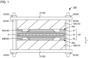
- FIG. 1 is a schematic cross-sectional view exemplifying the battery pack in the present disclosure.
- battery pack 100 is provided with first battery 10A, second battery 10B, cooling member 20 arranged between the first battery 10A and the second battery 10B in a thickness direction z, and restraining member 30 that restrains the first battery 10A, the second battery 10B, and the cooling member 20 in the thickness direction z.
- FIG. 2A is a schematic cross-sectional view exemplifying the cooling member in the present disclosure
- FIG. 2B is a schematic plan view exemplifying the cooling member in the present disclosure
- FIG. 2A corresponds to the cross-sectional view of A-A in FIG. 2B
- the cooling member 20 includes first surface 25a, first convex part 26a that surrounds outer periphery O1 of the first surface 25a and protrudes to the first battery side (upper side of the drawing in FIG.
- second surface 25b positioned on the opposite side to the first surface 25a, and second convex part 26b that surrounds an outer periphery (not illustrated) of the second surface 25b and protrudes to the second battery side (down side of the drawing in FIG. 2A ) on the basis of the second surface 25b in the thickness direction z.
- first heat conductive material layer 40A is arranged on the first surface 25a and second heat conductive material layer 40B is arranged on the second surface 25b.
- the first heat conductive material layer 40A includes first region 45A of which height is the same as the height of the first convex part 26a, and the second heat conductive material layer 40B includes second region 45B of which height is the same as the height of the second convex part 26b.
- the cooling member includes the first convex part and the second convex part, and the first heat conductive material layer is arranged on the first surface of the cooling member and the second heat conductive material layer is arranged on the second surface of the cooling member, so that the unevenness of the restraining pressure can be suppressed and the battery pack may exhibit excellent cooling performance.
- a cooling member may be arranged between two batteries facing to each other. By arranging the cooling member, deterioration of the battery over time due to generation of heat in battery reactions can be inhibited. Also, in the battery pack including a plurality of batteries, for example, in order to inhibit shifting of batteries in a direction orthogonal to the thickness direction of the batteries, restraining pressure may be applied to the thickness direction of the plurality of batteries.
- the cooling member since the cooling member includes the first convex part and the second convex part, the unevenness of the restraining pressure can be suppressed. Further, since the first heat conductive material layer is arranged on the first surface of the cooling member and the second heat conductive material layer is arranged on the second surface of the cooling member, and thus cooling of the battery by the cooling member may be excellent.
- the battery pack in the present disclosure includes at least a first battery and a second battery.
- a battery arranged in one surface side is defined as the first battery
- a battery arranged in the other surface side is defined as the second battery.
- the battery in the present disclosure usually includes an electrode.
- the electrode includes a current collector, and an electrode layer (cathode active material layer or anode active material layer) arranged on at least one surface of the current collector.
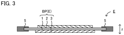
- FIG. 3 is a schematic cross-sectional view exemplifying the electrode in the present disclosure.
- the electrode E is, for example, a bipolar electrode BP including current collector 1, cathode active material layer 2 arranged on one surface of the current collector 1, and anode active material layer 3 arranged on the other surface of the current collector 1 in a thickness direction z.
- FIG. 4 is a schematic cross-sectional view exemplifying the battery in the present disclosure.
- battery 10 preferably includes a plurality of electrode E layered in the thickness direction z.
- the battery 10 shown in FIG. 4 includes, as the electrode E, bipolar electrode BP 1 , bipolar electrode BP 2 , cathode side end electrode CA, and anode side end electrode AN.
- the bipolar electrode BP 1 and the bipolar electrode BP 2 respectively include current collector 1, cathode active material layer 2 arranged on one surface of the current collector 1, and anode active material layer 3 arranged on the other surface of the current collector 1.
- the cathode side end electrode CA includes current collector 1, and cathode active material layer 2 arranged on one surface of the current collector 1.
- the anode side end electrode AN includes current collector 1, and anode active material layer 3 arranged on one surface of the current collector 1.
- the battery in the present disclosure may not include the bipolar electrode.
- the battery 10 usually includes power generating element U (U 1 to U 3 ).
- the power generating unit U includes cathode active material layer 2, anode active material layer 3, and separator (electrolyte layer) 4 arranged between the cathode active material layer 2 and the anode active material layer 3.
- the power generating unit U shown in FIG. 4 is sealed with sealing member 5 and cover member 6, and filled with liquid electrolyte 7 inside.
- the cathode active material layer 2, the anode active material layer 3, and the separator 4 are respectively impregnated with the liquid electrolyte.
- the battery in the present disclosure may include one of the power generating unit, and may include two or more thereof.
- the battery 10 in FIG. 4 includes a plurality of power generating units (U 1 , U 2 , U 3 ) layered in the thickness direction z. As shown in FIG. 4 , the plurality of power generating units may be connected to each other in series. Also, although not illustrated in particular, the plurality of power generating units may be connected to each other in parallel. The plurality of power generating units are each independent so that the liquid electrolyte does not circulate to each other. In FIG. 4 , the plurality of power generating units U 1 to U 3 are each independent so that the liquid electrolyte does not circulate to each other. For example, the power generating unit U 1 and the power generating unit U 2 are divided by the current collector 1 and the seal member 5, and thus are each independent. As shown in FIG. 4 , the battery 10 preferably includes a plurality of electrode E layered in the thickness direction z, and the seal member 5 arranged along with the outer periphery of the plurality of electrode E when viewed from the thickness direction z.
- the shape of the battery in a plan view is, for example, square such as foursquare.
- the length of each side configuring the shape of the battery in a plan view is, for example, 30 cm or more, may be 60 cm or more, and may be 1 m or more. Meanwhile, the length of each side is, for example, 3 m or less.
- a battery arranged in one surface side is defined as the first battery, and a battery arranged in the other surface side is defined as the second battery.
- the number of electrode may be the same or different.
- the number of power generating unit may be the same or different.
- the cooling member in the present disclosure is arranged between the first battery and the second battery in the thickness direction.
- cooling member 20 includes first surface 25a, first convex part 26a that surrounds outer periphery O1 of the first surface 25a and protrudes to the first battery side (upper side of the drawing in FIG. 2A ) on the basis of the first surface 25a in the thickness direction z, second surface 25b positioned on the opposite side to the first surface 25a, and second convex part that surrounds an outer periphery (not illustrated) of the second surface 25b and protrudes to the second battery side (down side of the drawing in FIG. 2A ) on the basis of the second surface 25b in the thickness direction z.
- the cooling member 20 preferably includes flow channel H that distributes a coolant.
- the first surface 25a is a surface of which normal direction is the thickness direction z.
- the first convex part 26a is arranged to surround the outer periphery O1 of the first surface 25a.
- the first convex part may be arranged to surround 50% or more of the outer periphery, may be arranged to surround 70% or more thereof, and may be arranged to surround 90% or more thereof.
- the first convex part may be arranged to surround the entire periphery of the first surface.
- the first convex part 26a may be arranged in a frame shape with respect to the first surface.
- the first convex part 26a protrudes to the first battery (upper side of the drawing in FIG. 2A ) side on the basis of the first surface 25a in the thickness direction z.
- the first convex part 26a is preferably capable of surface contact with the first battery (not illustrated). The reason therefor is to reduce resistance when the first convex part 26a is used as a conductive part.
- the second surface 25b is a surface positioned in the opposite side to the first surface 25a, and a surface of which normal direction is the thickness direction z.
- the second convex part is arranged to surround the outer periphery of the second surface.
- the second convex part 26b protrudes to the second battery side (down side of the drawing in FIG. 2A ) on the basis of the second surface 25b, in the thickness direction z. Details of the second convex part are the same as those of the first convex part described above, in which description "the first" can be appropriately replaced by "the second".
- the cooling member in the present disclosure may be a single member and may be a member configured by a plurality of members.
- FIGS. 5A, 5B and 5C are schematic cross-sectional views exemplifying the cooling member in the present disclosure.
- FIG. 5B and FIG. 5C respectively correspond to deal drawings.
- cooling member 20 may be a single member.
- the cooling member 20 may be a member configured by first member 21 including first surface 25a and first convex part 26a, and second member 22 including second surface 25b and second convex part 26b.
- a flat surface of the first member 21 and uneven surface of the second member form flow channel H.
- the cooling member 20 may be a member configured by first member 21 including first surface 25a and first convex part 26a, second member 22 including second surface 25b and second convex part 26b, and hollow member 23 arranged between the first member 21 and the second member 22 in the thickness direction.
- the hollow member 23 includes flow channel H that distributes a coolant, as a hollow part.
- FIG. 6A is a schematic plan view exemplifying the cooling member in the present disclosure
- FIG. 6B is a cross-sectional view of A-A in FIG. 6A
- first groove part 27a may be arranged in the first surface 25a of the cooling member 20.
- a temperature sensor such as a thermocouple
- the temperature of the battery pack can be more accurately monitored and controlled.
- a second groove part may be arranged in the second surface of the cooling member. Details of the second groove part are the same as those of the first groove part described above, in which description "the first" can be appropriately replaced by "the second".
- the first battery and the second battery may be electronically connected interposing the cooling member.
- the first battery and the second battery may be connected in series and may be connected in parallel.
- the first convex part and the second convex part are preferably a conducting part.
- the first battery and the second battery are electronically connected interposing at least the first convex part and the second convex part.
- the first convex part 26a in the cooling member 20 when viewed from the thickness direction z, is preferably arranged in a position overlapping the seal member 5 in the first battery 10A. In the same manner, when viewed from the thickness direction z, the first convex part 26a in the cooling member 20 is preferably arranged in a position overlapping the electrode E in the first battery 10A. Also, when viewed from the thickness direction z, the first surface 25a in the cooling member 20 is preferably arranged inside the outer periphery of the electrode E in the first battery 10A.
- the second convex part 26b in the cooling member 20 when viewed from the thickness direction z, is preferably arranged in a position overlapping the seal member 5 in the second battery 10B. In the same manner, when viewed from the thickness direction z, the second convex part 26b in the cooling member 20 is preferably arranged in a position overlapping the electrode E in the second battery 10B. Also, when viewed from the thickness direction z, the second surface 25b in the cooling member 20 is preferably arranged inside the outer periphery of the electrode E in the second battery 10B.
- H a designates the height of a part of the first convex part 26a protruding from the first surface 25a
- H b designates a part of the second convex part 26b protruding from the second surface 25b.
- the H a and the H b can be appropriately adjusted according to the size of the battery.
- the H a and the H b are respectively, for example, 0.70 mm or more, may be 1.00 mm or more, may be 1.20 mm or more, and may be 1.40 mm or more.
- the H a and the H b are respectively, for example, 2.20 mm or less, may be 2.00 mm or less, may be 1.80 mm or less, and may be 1.60 mm or less.
- cooling member there are no particular limitations on the material of the cooling member in the present disclosure, and examples thereof may include a metal such as aluminum, copper, iron and SUS.
- the battery pack in the present disclosure includes, as the heat conductive material layer, a first heat conductive material layer arranged on the first surface of the cooling member, and a second heat conductive material layer arranged on the second surface of the cooling member.
- the first heat conductive material layer includes a first region of which height is the same as a height of the first convex part
- the second heat conductive material layer includes a second region of which height is the same as a height of the second convex part.
- the first heat conductive material layer contacts both of the first surface of the cooling member and the first battery.
- the second heat conductive material layer contacts both of the second surface of the cooling member and the second battery.
- the first heat conductive material layer and the second heat conductive material layer usually include a heat conductive material.
- the heat resistance of the heat conductive material is, for example, 0.2 K/W or less.
- the volume resistance rate of the heat conductive material is, for example, 1 * 10 10 ⁇ cm or more.
- the dielectric breakdown voltage of the heat conductive material is, for example, 5 kV or more.
- the heat conductive material may include a heat dissipation grease that can be softened at a room temperature (such as CGW TM (registered trademark) series from SEKISUI POLYMATECH CO., LTD.).
- the first heat conductive material layer 40A includes first region 45A of which height is the same as the height H a of the first convex part 26a.
- the rate of the area of the first region 45A in the area of the first heat conductive material layer 40A may be 100%, and may be less than 100%. In the latter case, the rate is, for example, 50% or more, may be 70% or more, may be 90% or more, and may be 95% or more. Also, the rate of the area of the first heat conductive material layer with respect to the area of the first surface is, for example, 65% or more, may be 70% or more, may be 75% or more, and may be 80% or more. Meanwhile, the rate is, for example, 100% or less, may be 95% or less, may be 90% or less, and may be 85% or less.
- the second heat conductive material layer 40B includes second region 45B of which height is the same as a height H b of the second convex part 26b.
- the rate of the area of the second region 45B in the area of the second heat conductive material layer 40B may be 100%, and may be less than 100%. In the latter case, the rate is, for example, 50% or more, may be 70% or more, may be 90% or more, and may be 95% or more. Also, the rate of the area of the second heat conductive material layer with respect to the area of the second surface is, for example, 65% or more, may be 70% or more, may be 75% or more, and may be 80% or more. Meanwhile, the rate is, for example, 100% or less, may be 95% or less, may be 90% or less, and may be 85% or less.
- the restraining member in the present disclosure is a member that restrains the first battery, the second battery and the cooling member, in the thickness direction.
- restraining member in the present disclosure is not particularly limited if it is a member capable of restraining the first battery, the second battery and the cooling member in the thickness direction, and a conventionally known restraining member may be used.
- restraining member 30 shown in FIG. 1 includes a pair of end plate 31, connecting member 32 that connects the pair of end plate 31, and fixing member 33 that fixes the end plate 31 and the connecting member 32.
- the battery pack in the present disclosure includes two or more batteries.
- the battery pack may include three or more batteries, and may include four or more batteries.
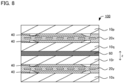
- FIG. 8 is a schematic cross-sectional view exemplifying the battery pack in the present disclosure. Incidentally, for convenience, the description of the restraining member is omitted.
- Battery pack 100 shown in FIG. 8 includes four battery 10 (10p, 10q, 10r, 10s).
- battery 10p arranged in one surface side corresponds to the first battery
- battery 10q arranged in the other surface side corresponds to the second battery.
- battery 10r arranged in one surface side corresponds to the first battery
- battery 10s arranged in the other surface side corresponds to the second battery.
- adhesive agent layer 60 may be arranged between adjacent batteries (battery 10q and battery 10r). By arranging the adhesive agent layer 60, positional deflection in a direction (left and right direction on the paper) orthogonal to the thickness direction z can be inhibited.
- the battery pack in the present disclosure is typically a lithium ion secondary battery.
- Examples of the applications of the battery pack may include a power source for vehicles such as hybrid electric vehicles (HEV), plug-in hybrid electric vehicles (PHEV), battery electric vehicles (BEV), gasoline-fueled automobiles and diesel powered automobiles.
- a power source for vehicles such as hybrid electric vehicles (HEV), plug-in hybrid electric vehicles (PHEV), and battery electric vehicles (BEV).
- HEV hybrid electric vehicles
- PHEV plug-in hybrid electric vehicles
- BEV battery electric vehicles
- the battery pack in the present disclosure may be used as a power source for moving bodies other than vehicles (such as rail road transportation, vessel and airplane), and may be used as a power source for electronic products such as information processing equipment.
- the method for producing a battery pack in the present disclosure is a method for producing the battery pack described above. Also, as shown in FIG. 9 , the method for producing the battery pack in the present disclosure includes a battery preparing step, a cooling member preparing step, a first precursor layer forming step, a first heat conductive material layer forming step, a second precursor layer forming step and a second heat conductive material layer forming step.
- the present disclosure features the points of using the specified cooling member, forming the specified heat conductive material layer, and that the cross-sectional shape of the precursor layer has a convex shape.
- the cooling member including the first convex part and the second convex part, and further forming the heat conductive material layer between the cooling member and the battery, excellent cooling performance can be obtained while suppressing the unevenness of the restraining pressure.
- the cross-sectional shape of the precursor layer is a convex shape, and thus remaining of bubbles can be suppressed.
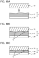
- FIG. 10A for example, when precursor layer 41 is formed on a surface of the cooling member 20 by a printing method, minute concave and convex are formed on the surface of the precursor layer 41 that is the battery 10 side. In particular, when a heat conductive material with high viscosity is used, minute concave and convex are easily formed.
- FIG. 10B when the battery 10 and the cooling member 20 are pressurized in a state the minute concave and convex are formed, the minute concave and convex will not disappear but remain on the surface of the precursor layer 41 that is the battery 10 side.
- FIG. 10C heat conductive material layer 40 in which babble V remains is formed. The bubble V works as a heat insulating layer, and thus cooling of the battery 10 by the cooling member 20 is inhibited.
- the precursor layer 41 of which cross-sectional shape is a convex shape is formed.
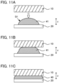
- the convex shape refers to a shape of which center protrudes more than the both edges. Since the cross-sectional shape of the precursor layer 41 is the convex shape, as shown in FIG. 11B , when the precursor layer 41 is pressurized in the thickness direction z, the precursor layer 41 is deformed to be widened to the direction (left and right direction on the paper) orthogonal to the thickness direction. On the occasion of the deformation, air is pushed out. As a result, as shown in FIG. 11C , the heat conductive material layer 40 in which remaining of bubbles is suppressed is formed.
- the battery preparing step in the present disclosure is a step of preparing the first battery and the second battery.
- the first battery and the second battery are in the same contents as those described in "A. Battery pack"; thus, the descriptions herein are omitted.
- FIGS. 12A to 12C are schematic cross-sectional views exemplifying the battery preparing step.
- bipolar electrode BP 1 and bipolar electrode BP 2 are prepared.
- the bipolar electrode BP 1 and the bipolar electrode BP 2 respectively include frame member 5a and 5b for forming seal member, arranged along with the outer periphery of the current collector 1.
- the anode active material layer 3 in the bipolar electrode BP 1 and the cathode active material layer 2 in the bipolar electrode BP 2 are faced to each other interposing separator 4. On this occasion, at least a part of the outer periphery of the separator 4 is arranged between the frame member 5a and the frame member 5b. Also, as shown in FIG.
- nest ⁇ and frame member (spacer) 5c are arranged between the frame member 5a in the bipolar electrode BP 1 and the frame member 5b in the bipolar electrode BP 2 .
- cathode side end electrode CA and anode side end electrode AN are also layered.
- a plurality of frame members layered are welded to form the seal member 5.
- a layered member shown in FIG. 12B is obtained.
- FIG. 12C by pulling out the nest ⁇ from the obtained layered member, penetration hole ⁇ that penetrates the seal member 5 is formed.
- a liquid electrolyte is injected from the penetration hole, and after the injection, the penetration hole is sealed with a resin. In this manner, battery 10 shown in FIG. 4 is obtained.
- the cooling member preparing step in the present disclosure is a step of preparing the cooling member.
- the cooling member is in the same contents as those described in "A. Battery pack"; thus, the descriptions herein are omitted.
- the first precursor layer forming step in the present disclosure is a step of forming a first precursor layer by coating the first surface of the cooling member with a heat conductive material.
- the heat conductive material is in the same contents as those described in "A. Battery pack"; thus, the descriptions herein are omitted.
- the method for applying the heat conductive material may include a method of applying the heat conductive material in a line shape or a dot shape using a nozzle.
- the heat conductive material When the heat conductive material is applied in a line shape or a dot shape, it may be applied in one line or may be applied in two lines or more along with a first direction.
- the heat conductive material when the above described first groove part is arranged in the first surface, it is preferable that the heat conductive material is not applied to the first groove part.
- the cross-sectional shape of the first precursor layer viewed from the thickness direction is usually a convex shape.
- the shape of the cross-section cut from the thickness direction of the first precursor layer along with the direction orthogonal to the direction the line extends is preferably a convex shape.
- the precursor layer 41 preferably includes arc-shaped surface S1.
- the first precursor layer preferably includes a first protruding region that protrudes more than the first convex part in the thickness direction.
- the rate of the height of the first protruding region with respect to the height of the first convex part is, for example, 1.01 or more and 1.30 or less. Also, when viewed from the thickness direction, the rate of the area of the first protruding region with respect to the area of the first precursor layer is usually less than 100%. Meanwhile, the rate is, for example, 50% or more and may be 70% or more.
- the first heat conductive material layer forming step in the present disclosure is a step of forming the first heat conductive material layer from the first precursor layer by arranging the first battery on the first convex part in the cooling member, after the first precursor layer forming step.
- the first precursor layer is pressurized by the first battery to form the first heat conductive material layer.
- the above described first region is formed.
- the first battery is arranged in an upper side of the gravity direction relative to the first convex part in the cooling member, and the first battery is arranged on the first convex part in the cooling member.
- the first precursor layer may be pressurized by the weight of the first battery itself, and the first precursor layer may be pressurized in the manner the first battery and the cooling member are pressurized by a pressure device, but the latter is preferred. The reason therefor is to further prevent bubbles from remaining.
- the details of the first heat conductive material layer are in the same contents as those described in "A. Battery pack" above.
- the second precursor layer forming step in the present disclosure is a step of forming a second precursor layer by coating the second surface of the cooling member with a heat conductive material. Details of the second precursor layer forming step are in the same contents as those described in the first precursor layer forming step described above, in which description "the first" can be appropriately replaced by "the second".
- the second heat conductive material layer forming step in the present disclosure is a step of forming the second heat conductive material layer from the second precursor layer by arranging the second battery on the second convex part in the cooling member, after the second precursor layer forming step.
- the details of the second heat conductive material layer forming step are in the same contents as those of the first heat conductive material layer forming step described above, in which "the first" can be appropriately replaced by "the second".
- the method for producing the battery pack in the present disclosure may include a restraining step of restraining the first battery, the second battery and the cooling member in the thickness direction using a restraining member, for example, after the first heat conductive material layer forming step and the second heat conductive material layer forming step.
- the restraining member is in the same contents as those described in "A. Battery pack"; thus, the descriptions herein are omitted.
- the battery pack produced by the above described method is in the same contents as those described in "A. Battery pack”; thus, the descriptions herein are omitted.
- the present disclosure is not limited to the embodiments.
- the embodiments are exemplification, and any other variations are intended to be included in the technical scope of the present disclosure if they have substantially the same constitution as the technical idea described in the claims of the present disclosure and have similar operation and effect thereto.
Landscapes
- Chemical & Material Sciences (AREA)
- Chemical Kinetics & Catalysis (AREA)
- Electrochemistry (AREA)
- General Chemical & Material Sciences (AREA)
- Engineering & Computer Science (AREA)
- Manufacturing & Machinery (AREA)
- Secondary Cells (AREA)
- Battery Mounting, Suspending (AREA)
- Connection Of Batteries Or Terminals (AREA)
Abstract
A main object of the present disclosure is to provide a battery pack with excellent cooling performance in which unevenness of restraining pressure can be suppressed. The present disclosure achieves the object by providing a battery pack including a first battery, a second battery, a cooling member arranged between the first battery and the second battery in a thickness direction, and a restraining member that restrains the first battery, the second battery and the cooling member in the thickness direction, wherein the cooling member includes a first surface, a first convex part that surrounds an outer periphery of the first surface and protrudes to the first battery side on the basis of the first surface in the thickness direction, a second surface positioned on the opposite side to the first surface, and a second convex part that surrounds an outer periphery of the second surface and protrudes to the second battery side on the basis of the second surface in the thickness direction; a first heat conductive material layer is arranged on the first surface and a second heat conductive material layer is arranged on the second surface; the first heat conductive material layer includes a first region of which height is the same as a height of the first convex part; and the second heat conductive material layer includes a second region of which height is the same as a height of the second convex part.
Description
- The present disclosure relates to a battery pack and a method for producing a battery pack.
- The development of batteries such as a lithium ion secondary battery has been actively carried out. For example,
Patent Literature 1 discloses a bipolar type battery including: a bipolar electrode that includes a bipolar current collecting foil, a cathode mixture layer, and an anode mixture layer; and a unit cell that includes a cathode including a cathode current collecting foil and a cathode mixture layer, and an anode including an anode current collecting foil and an anode mixture layer. Also,Patent Literature 2 discloses a storage device provided with a plurality of storage cells layered in a first direction, and a heat conductive material arranged between the plurality of storage cells. Also, although it is not a technique relating to a battery,Patent Literature 3 discloses a coating nozzle capable of applying high viscosity paint with excellent and smooth coating appearance in a thin film and with appropriate pattern width. -
- Patent Literature 1: Japanese Patent Application Laid-Open (
JP-A) No. 2017-195076 - Patent Literature 2:
JP-A No. 2022-135610 - Patent Literature 3:
JP-A No. 2014-155904 - In a battery pack including a plurality of batteries, a cooling member may be arranged between two batteries facing to each other. Also, in the battery pack including a plurality of batteries, for example, in order to inhibit shifting of batteries in a direction orthogonal to the thickness direction of the batteries, restraining pressure may be applied to the thickness direction of the plurality of batteries. Arrangement of a frame shaped convex part in the cooling member is considered to prevent the unevenness of restraining pressure. Although the unevenness of the restraining pressure can be prevented by arranging the frame shaped convex part in the cooling member, there will be a space between the cooling member and the battery, and thus cooling of the battery by the cooling member may be insufficient.
- The present disclosure has been made in view of the above circumstances, and a main object thereof is to provide a battery pack with excellent cooling performance in which unevenness of restraining pressure can be suppressed.
-
- [1] A battery pack including a first battery, a second battery, a cooling member arranged between the first battery and the second battery in a thickness direction, and a restraining member that restrains the first battery, the second battery and the cooling member in the thickness direction, wherein the cooling member includes a first surface, a first convex part that surrounds an outer periphery of the first surface and protrudes to the first battery side on the basis of the first surface in the thickness direction, a second surface positioned on the opposite side to the first surface, and a second convex part that surrounds an outer periphery of the second surface and protrudes to the second battery side on the basis of the second surface in the thickness direction; a first heat conductive material layer is arranged on the first surface and a second heat conductive material layer is arranged on the second surface; the first heat conductive material layer includes a first region of which height is the same as a height of the first convex part; and the second heat conductive material layer includes a second region of which height is the same as a height of the second convex part.
- [2] The battery pack according [1], wherein the first battery and the second battery are electronically connected interposing the cooling member, and the first convex part and the second convex part are a conducting part.
- [3] The battery pack according to [1] or [2], wherein the cooling member includes: a first member including the first surface and the first convex part; a second member including the second surface and the second convex part; and a hollow member arranged between the first member and the second member in the thickness direction.
- [4] The battery pack according to any one of [1] to [3], wherein a first groove part is arranged in the first surface of the cooling member; and a second groove part is arranged in the second surface of the cooling member.
- [5] The battery pack according to any one of [1] to [4], wherein each of a rate of an area of the first heat conductive material layer relative to an area of the first surface, and a rate of an area of the second heat conductive material layer relative to an area of the second surface is 65% or more and 100% or less.
- [6] The battery pack according to any one of [1] to [5], wherein each of the first battery and the second battery includes at least one bipolar electrode.
- [7] A method for producing the battery pack according to any one of [1] to [6], the method comprising: a battery preparing step of preparing the first battery and the second battery; a cooling member preparing step of preparing the cooling member; a first precursor layer forming step of forming a first precursor layer by coating the first surface of the cooling member with a heat conductive material; a first heat conductive material layer forming step of forming the first heat conductive material layer from the first precursor layer by arranging the first battery on the first convex part in the cooling member, after the first precursor layer forming step; a second precursor layer forming step of forming a second precursor layer by coating the second surface of the cooling member with a heat conductive material; and a second heat conductive material layer forming step of forming the second heat conductive material layer from the second precursor layer by arranging the second battery on the second convex part in the cooling member, after the second precursor layer forming step, wherein a shape of cross-section of each of the first precursor layer and the second precursor layer viewed from the thickness direction is a convex shape.
- [8] The method for producing the battery pack according to [7], wherein the convex shape includes an arc-shaped surface.
- [9] The method for producing the battery pack according to [7] or [8], wherein the first precursor layer includes a first protruding region that protrudes more than the first convex part in the thickness direction; and the second precursor layer includes a second protruding region that protrudes more than the second convex part in the thickness direction.
- The present disclosure exhibits an effect of providing a battery pack with excellent cooling performance in which unevenness of restraining pressure can be suppressed.
-
-
FIG. 1 is a schematic cross-sectional view exemplifying the battery pack in the present disclosure. -
FIGS. 2A and 2B are schematic cross-sectional view and a schematic plan view exemplifying the cooling member and the heat conductive material layer in the present disclosure. -
FIG. 3 is a schematic cross-sectional view exemplifying the electrode in the present disclosure. -
FIG. 4 is a schematic cross-sectional view exemplifying the battery in the present disclosure. -
FIGS. 5A to 5C are schematic cross-sectional views exemplifying the cooling member in the present disclosure. -
FIGS. 6A and 6B are schematic plan view and a schematic cross-sectional view exemplifying the cooling member in the present disclosure. -
FIG. 7 is a schematic cross-sectional view exemplifying the battery and the cooling member in the present disclosure. -
FIG. 8 is a schematic cross-sectional view exemplifying the battery pack in the present disclosure. -
FIG. 9 is a flow chart exemplifying the method for producing the battery pack in the present disclosure. -
FIGS. 10A to 10C are schematic cross-sectional views explaining the mechanism by which bubbles remain. -
FIGS. 11A to 11C are schematic cross-sectional views explaining the mechanism preventing bubbles from remaining. -
FIGS. 12A to 12C are schematic cross-sectional views exemplifying the battery preparing step in the present disclosure. - The embodiments in the present disclosure will be hereinafter explained in details with reference to drawings. Each drawing described as below is a schematic view, and the size and the shape of each portion are appropriately exaggerated in order to be understood easily. Furthermore, in the present description, upon expressing an embodiment of arranging one member with respect to the other member, when it is expressed simply "on" or "below", both of when the other member is directly arranged on or below the one member so as to contact with each other, and when the other member is arranged above or below the one member interposing an additional member, can be included unless otherwise described.
-
FIG. 1 is a schematic cross-sectional view exemplifying the battery pack in the present disclosure. As shown inFIG. 1 ,battery pack 100 is provided withfirst battery 10A,second battery 10B,cooling member 20 arranged between thefirst battery 10A and thesecond battery 10B in a thickness direction z, and restrainingmember 30 that restrains thefirst battery 10A, thesecond battery 10B, and thecooling member 20 in the thickness direction z. -
FIG. 2A is a schematic cross-sectional view exemplifying the cooling member in the present disclosure, andFIG. 2B is a schematic plan view exemplifying the cooling member in the present disclosure.FIG. 2A corresponds to the cross-sectional view of A-A inFIG. 2B . Incidentally, for convenience, descriptions of the first battery and the second battery are omitted inFIGS. 2A and 2B . As shown inFIGS. 2A and 2B , thecooling member 20 includesfirst surface 25a, first convexpart 26a that surrounds outer periphery O1 of thefirst surface 25a and protrudes to the first battery side (upper side of the drawing inFIG. 2A ) on the basis of thefirst surface 25a in the thickness direction z,second surface 25b positioned on the opposite side to thefirst surface 25a, and secondconvex part 26b that surrounds an outer periphery (not illustrated) of thesecond surface 25b and protrudes to the second battery side (down side of the drawing inFIG. 2A ) on the basis of thesecond surface 25b in the thickness direction z. - As shown in
FIG. 2A , first heatconductive material layer 40A is arranged on thefirst surface 25a and second heatconductive material layer 40B is arranged on thesecond surface 25b. The first heatconductive material layer 40A includesfirst region 45A of which height is the same as the height of the firstconvex part 26a, and the second heatconductive material layer 40B includessecond region 45B of which height is the same as the height of the secondconvex part 26b. - According to the present disclosure, the cooling member includes the first convex part and the second convex part, and the first heat conductive material layer is arranged on the first surface of the cooling member and the second heat conductive material layer is arranged on the second surface of the cooling member, so that the unevenness of the restraining pressure can be suppressed and the battery pack may exhibit excellent cooling performance.
- As described above, in the battery pack including a plurality of batteries, a cooling member may be arranged between two batteries facing to each other. By arranging the cooling member, deterioration of the battery over time due to generation of heat in battery reactions can be inhibited. Also, in the battery pack including a plurality of batteries, for example, in order to inhibit shifting of batteries in a direction orthogonal to the thickness direction of the batteries, restraining pressure may be applied to the thickness direction of the plurality of batteries.
- When the restraining pressure is applied, there may be unevenness of the restraining pressure to be actually applied, deriving from, for example, the deflection of the battery. In particular, the deflection easily occurs in a large-scaled battery, and thus the unevenness of the restraining pressure becomes remarkable. Arrangement of a frame shaped convex part in the cooling member is considered to prevent the unevenness of restraining pressure. Although the unevenness of the restraining pressure can be prevented by arranging the frame shaped convex part in the cooling member, there will be a space between the cooling member and the battery, and thus cooling of the battery by the cooling member may be insufficient.
- In contrast, in the present disclosure, since the cooling member includes the first convex part and the second convex part, the unevenness of the restraining pressure can be suppressed. Further, since the first heat conductive material layer is arranged on the first surface of the cooling member and the second heat conductive material layer is arranged on the second surface of the cooling member, and thus cooling of the battery by the cooling member may be excellent.
- The battery pack in the present disclosure includes at least a first battery and a second battery. In the present disclosure, on the basis of the cooling member, a battery arranged in one surface side is defined as the first battery, and a battery arranged in the other surface side is defined as the second battery.
- The battery in the present disclosure usually includes an electrode. The electrode includes a current collector, and an electrode layer (cathode active material layer or anode active material layer) arranged on at least one surface of the current collector.
FIG. 3 is a schematic cross-sectional view exemplifying the electrode in the present disclosure. As shown inFIG. 3 , the electrode E is, for example, a bipolar electrode BP includingcurrent collector 1, cathodeactive material layer 2 arranged on one surface of thecurrent collector 1, and anodeactive material layer 3 arranged on the other surface of thecurrent collector 1 in a thickness direction z. -
FIG. 4 is a schematic cross-sectional view exemplifying the battery in the present disclosure. As shown inFIG. 4 ,battery 10 preferably includes a plurality of electrode E layered in the thickness direction z. Thebattery 10 shown inFIG. 4 includes, as the electrode E, bipolar electrode BP1, bipolar electrode BP2, cathode side end electrode CA, and anode side end electrode AN. The bipolar electrode BP1 and the bipolar electrode BP2 respectively includecurrent collector 1, cathodeactive material layer 2 arranged on one surface of thecurrent collector 1, and anodeactive material layer 3 arranged on the other surface of thecurrent collector 1. The cathode side end electrode CA includescurrent collector 1, and cathodeactive material layer 2 arranged on one surface of thecurrent collector 1. The anode side end electrode AN includescurrent collector 1, and anodeactive material layer 3 arranged on one surface of thecurrent collector 1. Incidentally, the battery in the present disclosure may not include the bipolar electrode. - As shown in
FIG. 4 , thebattery 10 usually includes power generating element U (U1 to U3). The power generating unit U includes cathodeactive material layer 2, anodeactive material layer 3, and separator (electrolyte layer) 4 arranged between the cathodeactive material layer 2 and the anodeactive material layer 3. The power generating unit U shown inFIG. 4 is sealed with sealingmember 5 and covermember 6, and filled withliquid electrolyte 7 inside. As a result, the cathodeactive material layer 2, the anodeactive material layer 3, and theseparator 4 are respectively impregnated with the liquid electrolyte. Also, the battery in the present disclosure may include one of the power generating unit, and may include two or more thereof. - The
battery 10 inFIG. 4 includes a plurality of power generating units (U1, U2, U3) layered in the thickness direction z. As shown inFIG. 4 , the plurality of power generating units may be connected to each other in series. Also, although not illustrated in particular, the plurality of power generating units may be connected to each other in parallel. The plurality of power generating units are each independent so that the liquid electrolyte does not circulate to each other. InFIG. 4 , the plurality of power generating units U1 to U3 are each independent so that the liquid electrolyte does not circulate to each other. For example, the power generating unit U1 and the power generating unit U2 are divided by thecurrent collector 1 and theseal member 5, and thus are each independent. As shown inFIG. 4 , thebattery 10 preferably includes a plurality of electrode E layered in the thickness direction z, and theseal member 5 arranged along with the outer periphery of the plurality of electrode E when viewed from the thickness direction z. - The shape of the battery in a plan view (shape viewed from the thickness direction) is, for example, square such as foursquare. The length of each side configuring the shape of the battery in a plan view is, for example, 30 cm or more, may be 60 cm or more, and may be 1 m or more. Meanwhile, the length of each side is, for example, 3 m or less.
- As described above, in the present disclosure, on the basis of the cooling member, a battery arranged in one surface side is defined as the first battery, and a battery arranged in the other surface side is defined as the second battery. In the first battery and the second battery, the number of electrode may be the same or different. Likewise, in the first battery and the second battery, the number of power generating unit may be the same or different.
- The cooling member in the present disclosure is arranged between the first battery and the second battery in the thickness direction.
- As shown in
FIG. 2A and FIG. 2B , coolingmember 20 includesfirst surface 25a, firstconvex part 26a that surrounds outer periphery O1 of thefirst surface 25a and protrudes to the first battery side (upper side of the drawing inFIG. 2A ) on the basis of thefirst surface 25a in the thickness direction z,second surface 25b positioned on the opposite side to thefirst surface 25a, and second convex part that surrounds an outer periphery (not illustrated) of thesecond surface 25b and protrudes to the second battery side (down side of the drawing inFIG. 2A ) on the basis of thesecond surface 25b in the thickness direction z. Also, as shown inFIG. 2A , the coolingmember 20 preferably includes flow channel H that distributes a coolant. - As shown in
FIG. 2A , thefirst surface 25a is a surface of which normal direction is the thickness direction z. Meanwhile, as shown inFIG. 2B , the firstconvex part 26a is arranged to surround the outer periphery O1 of thefirst surface 25a. Also, although not illustrated in particular, among the entire outer periphery of the first surface, the first convex part may be arranged to surround 50% or more of the outer periphery, may be arranged to surround 70% or more thereof, and may be arranged to surround 90% or more thereof. Also, the first convex part may be arranged to surround the entire periphery of the first surface. In other words, the firstconvex part 26a may be arranged in a frame shape with respect to the first surface. Also, as shown inFIG. 2A , the firstconvex part 26a protrudes to the first battery (upper side of the drawing inFIG. 2A ) side on the basis of thefirst surface 25a in the thickness direction z. The firstconvex part 26a is preferably capable of surface contact with the first battery (not illustrated). The reason therefor is to reduce resistance when the firstconvex part 26a is used as a conductive part. - As shown in
FIG. 2A , thesecond surface 25b is a surface positioned in the opposite side to thefirst surface 25a, and a surface of which normal direction is the thickness direction z. Also, although not illustrated in particular, the second convex part is arranged to surround the outer periphery of the second surface. Also, as shown inFIG. 2A , the secondconvex part 26b protrudes to the second battery side (down side of the drawing inFIG. 2A ) on the basis of thesecond surface 25b, in the thickness direction z. Details of the second convex part are the same as those of the first convex part described above, in which description "the first" can be appropriately replaced by "the second". - The cooling member in the present disclosure may be a single member and may be a member configured by a plurality of members.
FIGS. 5A, 5B and 5C are schematic cross-sectional views exemplifying the cooling member in the present disclosure. Incidentally,FIG. 5B and FIG. 5C respectively correspond to deal drawings. For example, as shown inFIG. 5A , coolingmember 20 may be a single member. On the other hand, as shown inFIG. 5B , the coolingmember 20 may be a member configured byfirst member 21 includingfirst surface 25a and firstconvex part 26a, andsecond member 22 includingsecond surface 25b and secondconvex part 26b. In the coolingmember 20 shown inFIG. 5B , a flat surface of thefirst member 21 and uneven surface of the second member form flow channel H. - As shown in
FIG. 5C , the coolingmember 20 may be a member configured byfirst member 21 includingfirst surface 25a and firstconvex part 26a,second member 22 includingsecond surface 25b and secondconvex part 26b, andhollow member 23 arranged between thefirst member 21 and thesecond member 22 in the thickness direction. Thehollow member 23 includes flow channel H that distributes a coolant, as a hollow part. -
FIG. 6A is a schematic plan view exemplifying the cooling member in the present disclosure, andFIG. 6B is a cross-sectional view of A-A inFIG. 6A . As shown inFIG. 6A and FIG. 6B ,first groove part 27a may be arranged in thefirst surface 25a of the coolingmember 20. For example, by arranging a temperature sensor such as a thermocouple in the first groove part, the temperature of the battery pack can be more accurately monitored and controlled. Also, although not illustrated in particular, a second groove part may be arranged in the second surface of the cooling member. Details of the second groove part are the same as those of the first groove part described above, in which description "the first" can be appropriately replaced by "the second". - In the present disclosure, the first battery and the second battery may be electronically connected interposing the cooling member. In this case, the first battery and the second battery may be connected in series and may be connected in parallel. Also, when the first battery and the second battery are electronically connected interposing the cooling member, the first convex part and the second convex part are preferably a conducting part. In other words, it is preferable that the first battery and the second battery are electronically connected interposing at least the first convex part and the second convex part.
- As shown in
FIG. 7 , when viewed from the thickness direction z, the firstconvex part 26a in the coolingmember 20 is preferably arranged in a position overlapping theseal member 5 in thefirst battery 10A. In the same manner, when viewed from the thickness direction z, the firstconvex part 26a in the coolingmember 20 is preferably arranged in a position overlapping the electrode E in thefirst battery 10A. Also, when viewed from the thickness direction z, thefirst surface 25a in the coolingmember 20 is preferably arranged inside the outer periphery of the electrode E in thefirst battery 10A. - As shown in
FIG. 7 , when viewed from the thickness direction z, the secondconvex part 26b in the coolingmember 20 is preferably arranged in a position overlapping theseal member 5 in thesecond battery 10B. In the same manner, when viewed from the thickness direction z, the secondconvex part 26b in the coolingmember 20 is preferably arranged in a position overlapping the electrode E in thesecond battery 10B. Also, when viewed from the thickness direction z, thesecond surface 25b in the coolingmember 20 is preferably arranged inside the outer periphery of the electrode E in thesecond battery 10B. - As shown in
FIG. 2A , in the thickness direction z, Ha designates the height of a part of the firstconvex part 26a protruding from thefirst surface 25a, and Hb designates a part of the secondconvex part 26b protruding from thesecond surface 25b. The Ha and the Hb can be appropriately adjusted according to the size of the battery. The Ha and the Hb are respectively, for example, 0.70 mm or more, may be 1.00 mm or more, may be 1.20 mm or more, and may be 1.40 mm or more. Meanwhile, the Ha and the Hb are respectively, for example, 2.20 mm or less, may be 2.00 mm or less, may be 1.80 mm or less, and may be 1.60 mm or less. - There are no particular limitations on the material of the cooling member in the present disclosure, and examples thereof may include a metal such as aluminum, copper, iron and SUS.
- The battery pack in the present disclosure includes, as the heat conductive material layer, a first heat conductive material layer arranged on the first surface of the cooling member, and a second heat conductive material layer arranged on the second surface of the cooling member. Also, the first heat conductive material layer includes a first region of which height is the same as a height of the first convex part, and the second heat conductive material layer includes a second region of which height is the same as a height of the second convex part. In the first region, usually, the first heat conductive material layer contacts both of the first surface of the cooling member and the first battery. Similarly, in the second region, usually, the second heat conductive material layer contacts both of the second surface of the cooling member and the second battery.
- The first heat conductive material layer and the second heat conductive material layer usually include a heat conductive material. The heat resistance of the heat conductive material is, for example, 0.2 K/W or less. Also, the volume resistance rate of the heat conductive material is, for example, 1 * 1010 Ω·cm or more. Also, the dielectric breakdown voltage of the heat conductive material is, for example, 5 kV or more. Examples of the heat conductive material may include a heat dissipation grease that can be softened at a room temperature (such as CGW™ (registered trademark) series from SEKISUI POLYMATECH CO., LTD.).
- As shown in
FIG. 2A , the first heatconductive material layer 40A includesfirst region 45A of which height is the same as the height Ha of the firstconvex part 26a. The rate of the area of thefirst region 45A in the area of the first heatconductive material layer 40A may be 100%, and may be less than 100%. In the latter case, the rate is, for example, 50% or more, may be 70% or more, may be 90% or more, and may be 95% or more. Also, the rate of the area of the first heat conductive material layer with respect to the area of the first surface is, for example, 65% or more, may be 70% or more, may be 75% or more, and may be 80% or more. Meanwhile, the rate is, for example, 100% or less, may be 95% or less, may be 90% or less, and may be 85% or less. - As shown in
FIG. 2A , the second heatconductive material layer 40B includessecond region 45B of which height is the same as a height Hb of the secondconvex part 26b. The rate of the area of thesecond region 45B in the area of the second heatconductive material layer 40B may be 100%, and may be less than 100%. In the latter case, the rate is, for example, 50% or more, may be 70% or more, may be 90% or more, and may be 95% or more. Also, the rate of the area of the second heat conductive material layer with respect to the area of the second surface is, for example, 65% or more, may be 70% or more, may be 75% or more, and may be 80% or more. Meanwhile, the rate is, for example, 100% or less, may be 95% or less, may be 90% or less, and may be 85% or less. - The restraining member in the present disclosure is a member that restrains the first battery, the second battery and the cooling member, in the thickness direction.
- The restraining member in the present disclosure is not particularly limited if it is a member capable of restraining the first battery, the second battery and the cooling member in the thickness direction, and a conventionally known restraining member may be used. For example, restraining
member 30 shown inFIG. 1 includes a pair ofend plate 31, connectingmember 32 that connects the pair ofend plate 31, and fixingmember 33 that fixes theend plate 31 and the connectingmember 32. - The battery pack in the present disclosure includes two or more batteries. In the present disclosure, the battery pack may include three or more batteries, and may include four or more batteries.
- As described above, in the present disclosure, on the basis of the cooling member, a battery arranged in one surface side is defined as the first battery, and a battery arranged in the other surface side is defined as the second battery.
FIG. 8 is a schematic cross-sectional view exemplifying the battery pack in the present disclosure. Incidentally, for convenience, the description of the restraining member is omitted.Battery pack 100 shown inFIG. 8 includes four battery 10 (10p, 10q, 10r, 10s). On the basis of the coolingmember 20x,battery 10p arranged in one surface side corresponds to the first battery, andbattery 10q arranged in the other surface side corresponds to the second battery. Also, on the basis of the coolingmember 20y,battery 10r arranged in one surface side corresponds to the first battery, andbattery 10s arranged in the other surface side corresponds to the second battery. - As shown in
FIG. 8 , in the thickness direction z,adhesive agent layer 60 may be arranged between adjacent batteries (battery 10q andbattery 10r). By arranging theadhesive agent layer 60, positional deflection in a direction (left and right direction on the paper) orthogonal to the thickness direction z can be inhibited. - The battery pack in the present disclosure is typically a lithium ion secondary battery. Examples of the applications of the battery pack may include a power source for vehicles such as hybrid electric vehicles (HEV), plug-in hybrid electric vehicles (PHEV), battery electric vehicles (BEV), gasoline-fueled automobiles and diesel powered automobiles. In particular, it is preferably used as a power source for driving hybrid electric vehicles (HEV), plug-in hybrid electric vehicles (PHEV), and battery electric vehicles (BEV). Also, the battery pack in the present disclosure may be used as a power source for moving bodies other than vehicles (such as rail road transportation, vessel and airplane), and may be used as a power source for electronic products such as information processing equipment.
- The method for producing a battery pack in the present disclosure is a method for producing the battery pack described above. Also, as shown in
FIG. 9 , the method for producing the battery pack in the present disclosure includes a battery preparing step, a cooling member preparing step, a first precursor layer forming step, a first heat conductive material layer forming step, a second precursor layer forming step and a second heat conductive material layer forming step. The present disclosure features the points of using the specified cooling member, forming the specified heat conductive material layer, and that the cross-sectional shape of the precursor layer has a convex shape. - According to the present disclosure, by using the cooling member including the first convex part and the second convex part, and further forming the heat conductive material layer between the cooling member and the battery, excellent cooling performance can be obtained while suppressing the unevenness of the restraining pressure. Also, the cross-sectional shape of the precursor layer is a convex shape, and thus remaining of bubbles can be suppressed.
- Here, the remaining of bubbles will be explained with reference to
FIGS. 10A to 10C andFIGS. 11A to 11C . As shown inFIG. 10A , for example, whenprecursor layer 41 is formed on a surface of the coolingmember 20 by a printing method, minute concave and convex are formed on the surface of theprecursor layer 41 that is thebattery 10 side. In particular, when a heat conductive material with high viscosity is used, minute concave and convex are easily formed. As shown inFIG. 10B , when thebattery 10 and the coolingmember 20 are pressurized in a state the minute concave and convex are formed, the minute concave and convex will not disappear but remain on the surface of theprecursor layer 41 that is thebattery 10 side. As a result, as shown inFIG. 10C , heatconductive material layer 40 in which babble V remains is formed. The bubble V works as a heat insulating layer, and thus cooling of thebattery 10 by the coolingmember 20 is inhibited. - In contrast, in the method for producing the battery pack in the present disclosure, as shown in
FIG. 11A , in the precursor layer forming step, theprecursor layer 41 of which cross-sectional shape is a convex shape is formed. The convex shape refers to a shape of which center protrudes more than the both edges. Since the cross-sectional shape of theprecursor layer 41 is the convex shape, as shown inFIG. 11B , when theprecursor layer 41 is pressurized in the thickness direction z, theprecursor layer 41 is deformed to be widened to the direction (left and right direction on the paper) orthogonal to the thickness direction. On the occasion of the deformation, air is pushed out. As a result, as shown inFIG. 11C , the heatconductive material layer 40 in which remaining of bubbles is suppressed is formed. - The battery preparing step in the present disclosure is a step of preparing the first battery and the second battery. The first battery and the second battery are in the same contents as those described in "A. Battery pack"; thus, the descriptions herein are omitted.
-
FIGS. 12A to 12C are schematic cross-sectional views exemplifying the battery preparing step. First, As shown inFIG. 12A , bipolar electrode BP1 and bipolar electrode BP2 are prepared. The bipolar electrode BP1 and the bipolar electrode BP2 respectively includeframe member current collector 1. Next, the anodeactive material layer 3 in the bipolar electrode BP1 and the cathodeactive material layer 2 in the bipolar electrode BP2 are faced to each other interposingseparator 4. On this occasion, at least a part of the outer periphery of theseparator 4 is arranged between theframe member 5a and theframe member 5b. Also, as shown inFIG. 12A , nest α and frame member (spacer) 5c are arranged between theframe member 5a in the bipolar electrode BP1 and theframe member 5b in the bipolar electrode BP2. Next, although not illustrated in particular, cathode side end electrode CA and anode side end electrode AN are also layered. After that, a plurality of frame members layered are welded to form theseal member 5. In this manner, a layered member shown inFIG. 12B is obtained. Next, as shown inFIG. 12C , by pulling out the nest α from the obtained layered member, penetration hole β that penetrates theseal member 5 is formed. Next, although not illustrated in particular, a liquid electrolyte is injected from the penetration hole, and after the injection, the penetration hole is sealed with a resin. In this manner,battery 10 shown inFIG. 4 is obtained. - The cooling member preparing step in the present disclosure is a step of preparing the cooling member. The cooling member is in the same contents as those described in "A. Battery pack"; thus, the descriptions herein are omitted.
- The first precursor layer forming step in the present disclosure is a step of forming a first precursor layer by coating the first surface of the cooling member with a heat conductive material. The heat conductive material is in the same contents as those described in "A. Battery pack"; thus, the descriptions herein are omitted.
- There are no particular limitations on the method for applying the heat conductive material, and examples thereof may include a method of applying the heat conductive material in a line shape or a dot shape using a nozzle. When the heat conductive material is applied in a line shape or a dot shape, it may be applied in one line or may be applied in two lines or more along with a first direction. Incidentally, when the above described first groove part is arranged in the first surface, it is preferable that the heat conductive material is not applied to the first groove part.
- The cross-sectional shape of the first precursor layer viewed from the thickness direction is usually a convex shape. For example, if the first precursor layer is in a line shape when viewed from the thickness direction, the shape of the cross-section cut from the thickness direction of the first precursor layer along with the direction orthogonal to the direction the line extends, is preferably a convex shape. In specific, as shown in
FIG. 11A , theprecursor layer 41 preferably includes arc-shaped surface S1. - The first precursor layer preferably includes a first protruding region that protrudes more than the first convex part in the thickness direction. The rate of the height of the first protruding region with respect to the height of the first convex part is, for example, 1.01 or more and 1.30 or less. Also, when viewed from the thickness direction, the rate of the area of the first protruding region with respect to the area of the first precursor layer is usually less than 100%. Meanwhile, the rate is, for example, 50% or more and may be 70% or more.
- The first heat conductive material layer forming step in the present disclosure is a step of forming the first heat conductive material layer from the first precursor layer by arranging the first battery on the first convex part in the cooling member, after the first precursor layer forming step. In specific, the first precursor layer is pressurized by the first battery to form the first heat conductive material layer. Also, when the first precursor layer is pressurized by the first battery, the above described first region is formed.
- In the first heat conductive material layer forming step, it is preferable that the first battery is arranged in an upper side of the gravity direction relative to the first convex part in the cooling member, and the first battery is arranged on the first convex part in the cooling member. Also, on the occasion of arranging the first battery on the first convex part of the cooling member, the first precursor layer may be pressurized by the weight of the first battery itself, and the first precursor layer may be pressurized in the manner the first battery and the cooling member are pressurized by a pressure device, but the latter is preferred. The reason therefor is to further prevent bubbles from remaining. The details of the first heat conductive material layer are in the same contents as those described in "A. Battery pack" above.
- The second precursor layer forming step in the present disclosure is a step of forming a second precursor layer by coating the second surface of the cooling member with a heat conductive material. Details of the second precursor layer forming step are in the same contents as those described in the first precursor layer forming step described above, in which description "the first" can be appropriately replaced by "the second".
- The second heat conductive material layer forming step in the present disclosure is a step of forming the second heat conductive material layer from the second precursor layer by arranging the second battery on the second convex part in the cooling member, after the second precursor layer forming step. The details of the second heat conductive material layer forming step are in the same contents as those of the first heat conductive material layer forming step described above, in which "the first" can be appropriately replaced by "the second".
- The method for producing the battery pack in the present disclosure may include a restraining step of restraining the first battery, the second battery and the cooling member in the thickness direction using a restraining member, for example, after the first heat conductive material layer forming step and the second heat conductive material layer forming step. The restraining member is in the same contents as those described in "A. Battery pack"; thus, the descriptions herein are omitted.
- The battery pack produced by the above described method is in the same contents as those described in "A. Battery pack"; thus, the descriptions herein are omitted.
- Incidentally, the present disclosure is not limited to the embodiments. The embodiments are exemplification, and any other variations are intended to be included in the technical scope of the present disclosure if they have substantially the same constitution as the technical idea described in the claims of the present disclosure and have similar operation and effect thereto.
-
- 1
- current collector
- 2
- cathode active material layer
- 3
- anode active material layer
- 4
- separator
- E
- electrode
- BP
- bipolar electrode
- U
- power generating unit
- 10A
- first battery
- 10B
- second battery
- 20
- cooling member
- 21
- first member
- 22
- second member
- 23
- hollow member
- 30
- restraining member
- 40
- heat conductive material layer
- 100
- battery pack
Claims (9)
- A battery pack characterized by comprising a first battery, a second battery, a cooling member arranged between the first battery and the second battery in a thickness direction, and a restraining member that restrains the first battery, the second battery and the cooling member in the thickness direction, whereinthe cooling member includes a first surface, a first convex part that surrounds an outer periphery of the first surface and protrudes to the first battery side on the basis of the first surface in the thickness direction, a second surface positioned on the opposite side to the first surface, and a second convex part that surrounds an outer periphery of the second surface and protrudes to the second battery side on the basis of the second surface in the thickness direction;a first heat conductive material layer is arranged on the first surface and a second heat conductive material layer is arranged on the second surface;the first heat conductive material layer includes a first region of which height is the same as a height of the first convex part; andthe second heat conductive material layer includes a second region of which height is the same as a height of the second convex part.
- The battery pack according to claim 1, characterized in that the first battery and the second battery are electronically connected interposing the cooling member, and the first convex part and the second convex part are a conducting part.
- The battery pack according to claim 1, characterized in that the cooling member includes:a first member including the first surface and the first convex part;a second member including the second surface and the second convex part; anda hollow member arranged between the first member and the second member in the thickness direction.
- The battery pack according to claim 1, characterized in thata first groove part is arranged in the first surface of the cooling member; anda second groove part is arranged in the second surface of the cooling member.
- The battery pack according to claim 1, characterized in that each of a rate of an area of the first heat conductive material layer relative to an area of the first surface, and a rate of an area of the second heat conductive material layer relative to an area of the second surface is 65% or more and 100% or less.
- The battery pack according to claim 1, characterized in that each of the first battery and the second battery includes at least one bipolar electrode.
- A method for producing the battery pack according to any one of claims 1 to 6, the method characterized by comprising:a battery preparing step of preparing the first battery and the second battery;a cooling member preparing step of preparing the cooling member;a first precursor layer forming step of forming a first precursor layer by coating the first surface of the cooling member with a heat conductive material;a first heat conductive material layer forming step of forming the first heat conductive material layer from the first precursor layer by arranging the first battery on the first convex part in the cooling member, after the first precursor layer forming step;a second precursor layer forming step of forming a second precursor layer by coating the second surface of the cooling member with a heat conductive material; anda second heat conductive material layer forming step of forming the second heat conductive material layer from the second precursor layer by arranging the second battery on the second convex part in the cooling member, after the second precursor layer forming step, whereina shape of cross-section of each of the first precursor layer and the second precursor layer viewed from the thickness direction is a convex shape.
- The method for producing the battery pack according to claim 7, characterized in that the convex shape includes an arc-shaped surface.
- The method for producing the battery pack according to claim 7, characterized in thatthe first precursor layer includes a first protruding region that protrudes more than the first convex part in the thickness direction; andthe second precursor layer includes a second protruding region that protrudes more than the second convex part in the thickness direction.
Applications Claiming Priority (1)
| Application Number | Priority Date | Filing Date | Title |
|---|---|---|---|
| JP2023002128A JP7666531B2 (en) | 2023-01-11 | 2023-01-11 | Battery pack and method for manufacturing the battery pack |
Publications (1)
| Publication Number | Publication Date |
|---|---|
| EP4404317A1 true EP4404317A1 (en) | 2024-07-24 |
Family
ID=89474040
Family Applications (1)
| Application Number | Title | Priority Date | Filing Date |
|---|---|---|---|
| EP24150403.4A Pending EP4404317A1 (en) | 2023-01-11 | 2024-01-04 | Battery pack and method for producing battery pack |
Country Status (5)
| Country | Link |
|---|---|
| US (1) | US20240234849A1 (en) |
| EP (1) | EP4404317A1 (en) |
| JP (1) | JP7666531B2 (en) |
| KR (1) | KR102897543B1 (en) |
| CN (1) | CN118336196A (en) |
Citations (5)
| Publication number | Priority date | Publication date | Assignee | Title |
|---|---|---|---|---|
| US20100163325A1 (en) * | 2006-05-11 | 2010-07-01 | Yoshiyuki Nakamura | Assembled battery and vehicle |
| JP2014155904A (en) | 2013-02-15 | 2014-08-28 | Aisin Chemical Co Ltd | Coating nozzle for high viscous coating material |
| JP2017195076A (en) | 2016-04-20 | 2017-10-26 | 株式会社日立製作所 | Bipolar battery |
| US20200036063A1 (en) * | 2018-07-27 | 2020-01-30 | Mahle International Gmbh | Accumulator arrangement |
| JP2022135610A (en) | 2021-03-05 | 2022-09-15 | プライムプラネットエナジー&ソリューションズ株式会社 | Power storage device and manufacturing method for the same |
Family Cites Families (5)
| Publication number | Priority date | Publication date | Assignee | Title |
|---|---|---|---|---|
| KR20060102851A (en) * | 2005-03-25 | 2006-09-28 | 삼성에스디아이 주식회사 | Secondary battery module |
| JP4807595B2 (en) * | 2008-12-12 | 2011-11-02 | 本田技研工業株式会社 | Battery holding device |
| JP6534975B2 (en) * | 2016-08-16 | 2019-06-26 | トヨタ自動車株式会社 | Bipolar battery |
| JP6828470B2 (en) * | 2017-01-31 | 2021-02-10 | 株式会社豊田自動織機 | Power storage device |
| JP7063744B2 (en) * | 2018-06-27 | 2022-05-09 | 住友理工株式会社 | Cushioning sheet for battery module |
-
2023
- 2023-01-11 JP JP2023002128A patent/JP7666531B2/en active Active
- 2023-12-20 KR KR1020230186999A patent/KR102897543B1/en active Active
- 2023-12-29 US US18/400,645 patent/US20240234849A1/en active Pending
-
2024
- 2024-01-04 EP EP24150403.4A patent/EP4404317A1/en active Pending
- 2024-01-05 CN CN202410022097.XA patent/CN118336196A/en active Pending
Patent Citations (5)
| Publication number | Priority date | Publication date | Assignee | Title |
|---|---|---|---|---|
| US20100163325A1 (en) * | 2006-05-11 | 2010-07-01 | Yoshiyuki Nakamura | Assembled battery and vehicle |
| JP2014155904A (en) | 2013-02-15 | 2014-08-28 | Aisin Chemical Co Ltd | Coating nozzle for high viscous coating material |
| JP2017195076A (en) | 2016-04-20 | 2017-10-26 | 株式会社日立製作所 | Bipolar battery |
| US20200036063A1 (en) * | 2018-07-27 | 2020-01-30 | Mahle International Gmbh | Accumulator arrangement |
| JP2022135610A (en) | 2021-03-05 | 2022-09-15 | プライムプラネットエナジー&ソリューションズ株式会社 | Power storage device and manufacturing method for the same |
Also Published As
| Publication number | Publication date |
|---|---|
| CN118336196A (en) | 2024-07-12 |
| JP2024098570A (en) | 2024-07-24 |
| US20240234849A1 (en) | 2024-07-11 |
| KR102897543B1 (en) | 2025-12-08 |
| JP7666531B2 (en) | 2025-04-22 |
| KR20240112200A (en) | 2024-07-18 |
Similar Documents
| Publication | Publication Date | Title |
|---|---|---|
| US10569634B2 (en) | Multi-functional cooling channel and busbar for battery cell pack | |
| US20140079992A1 (en) | Bipolar all-solid-state battery | |
| KR101499471B1 (en) | Method for Manufacturing a secondary Battery and the secondary Battery Manufactured Thereby | |
| US20250007030A1 (en) | Battery cell pack for electric vehicle | |
| EP3933993B1 (en) | Battery, electrical apparatus and cell installation method | |
| US10680297B2 (en) | Tab cooling for pouch cell | |
| US20250007032A1 (en) | Battery module and battery | |
| EP3832752A1 (en) | Power supply device, vehicle having same, and buffer | |
| JP7471433B2 (en) | BATTERY, BATTERY MODULE, BATTERY PACK, AND ELECTRIC VEHICLE | |
| JP2022110002A (en) | power storage device, power storage device assembly, moving object | |
| EP4475253A1 (en) | Battery and electric device | |
| EP4404317A1 (en) | Battery pack and method for producing battery pack | |
| JP2018049794A (en) | Power storage device, and method for manufacturing the same | |
| EP4447208A1 (en) | Enclosure frame, battery, electric apparatus, and method and apparatus for manufacturing enclosure frame | |
| US20240313329A1 (en) | Battery module | |
| EP4401185A1 (en) | Method for producing battery module and battery module | |
| US12125613B2 (en) | Cable, battery and electricity consuming device | |
| US20240186583A1 (en) | Method for producing battery and battery | |
| KR20200093225A (en) | System for manufacturing secondary battery and method of thesame | |
| US20240266654A1 (en) | Battery and method for producing battery | |
| JP4539173B2 (en) | Inverter device and drive system using the same | |
| JP2011018481A (en) | Bipolar secondary battery | |
| EP4037087A1 (en) | Equipotential device, equipotential structure, battery and power consuming apparatus | |
| US20240243437A1 (en) | Solid-State Traction Battery Having Battery Cells with Electrical Insulator Coated Electrode Edge | |
| WO2017094436A1 (en) | Battery pack |
Legal Events
| Date | Code | Title | Description |
|---|---|---|---|
| PUAI | Public reference made under article 153(3) epc to a published international application that has entered the european phase |
Free format text: ORIGINAL CODE: 0009012 |
|
| STAA | Information on the status of an ep patent application or granted ep patent |
Free format text: STATUS: REQUEST FOR EXAMINATION WAS MADE |
|
| 17P | Request for examination filed |
Effective date: 20240121 |
|
| AK | Designated contracting states |
Kind code of ref document: A1 Designated state(s): AL AT BE BG CH CY CZ DE DK EE ES FI FR GB GR HR HU IE IS IT LI LT LU LV MC ME MK MT NL NO PL PT RO RS SE SI SK SM TR |