EP3933993B1 - Battery, electrical apparatus and cell installation method - Google Patents
Battery, electrical apparatus and cell installation method Download PDFInfo
- Publication number
- EP3933993B1 EP3933993B1 EP19921076.6A EP19921076A EP3933993B1 EP 3933993 B1 EP3933993 B1 EP 3933993B1 EP 19921076 A EP19921076 A EP 19921076A EP 3933993 B1 EP3933993 B1 EP 3933993B1
- Authority
- EP
- European Patent Office
- Prior art keywords
- current collector
- battery
- battery housing
- separator
- cell
- Prior art date
- Legal status (The legal status is an assumption and is not a legal conclusion. Google has not performed a legal analysis and makes no representation as to the accuracy of the status listed.)
- Active
Links
- 238000000034 method Methods 0.000 title claims description 79
- 238000009434 installation Methods 0.000 title claims description 32
- 239000013543 active substance Substances 0.000 claims description 49
- 238000003466 welding Methods 0.000 claims description 21
- 239000011248 coating agent Substances 0.000 claims description 12
- 238000000576 coating method Methods 0.000 claims description 12
- 238000010586 diagram Methods 0.000 description 22
- 230000017525 heat dissipation Effects 0.000 description 20
- 230000008569 process Effects 0.000 description 17
- 235000015110 jellies Nutrition 0.000 description 14
- 239000008274 jelly Substances 0.000 description 14
- 238000011900 installation process Methods 0.000 description 12
- 238000012546 transfer Methods 0.000 description 8
- HBBGRARXTFLTSG-UHFFFAOYSA-N Lithium ion Chemical compound [Li+] HBBGRARXTFLTSG-UHFFFAOYSA-N 0.000 description 6
- 238000001125 extrusion Methods 0.000 description 6
- 238000005096 rolling process Methods 0.000 description 6
- 239000000243 solution Substances 0.000 description 6
- 230000004888 barrier function Effects 0.000 description 5
- OKTJSMMVPCPJKN-UHFFFAOYSA-N Carbon Chemical compound [C] OKTJSMMVPCPJKN-UHFFFAOYSA-N 0.000 description 4
- PXHVJJICTQNCMI-UHFFFAOYSA-N Nickel Chemical compound [Ni] PXHVJJICTQNCMI-UHFFFAOYSA-N 0.000 description 4
- 239000000306 component Substances 0.000 description 4
- 230000008878 coupling Effects 0.000 description 4
- 238000010168 coupling process Methods 0.000 description 4
- 238000005859 coupling reaction Methods 0.000 description 4
- 238000002347 injection Methods 0.000 description 4
- 239000007924 injection Substances 0.000 description 4
- 239000007788 liquid Substances 0.000 description 4
- 229910001416 lithium ion Inorganic materials 0.000 description 4
- 239000011149 active material Substances 0.000 description 3
- 239000000956 alloy Substances 0.000 description 3
- 229910045601 alloy Inorganic materials 0.000 description 3
- 238000004519 manufacturing process Methods 0.000 description 3
- 239000000126 substance Substances 0.000 description 3
- RYGMFSIKBFXOCR-UHFFFAOYSA-N Copper Chemical compound [Cu] RYGMFSIKBFXOCR-UHFFFAOYSA-N 0.000 description 2
- 229910052782 aluminium Inorganic materials 0.000 description 2
- XAGFODPZIPBFFR-UHFFFAOYSA-N aluminium Chemical compound [Al] XAGFODPZIPBFFR-UHFFFAOYSA-N 0.000 description 2
- 230000008901 benefit Effects 0.000 description 2
- 230000015572 biosynthetic process Effects 0.000 description 2
- 238000004140 cleaning Methods 0.000 description 2
- 238000004891 communication Methods 0.000 description 2
- 239000004020 conductor Substances 0.000 description 2
- 229910052802 copper Inorganic materials 0.000 description 2
- 239000010949 copper Substances 0.000 description 2
- 238000007872 degassing Methods 0.000 description 2
- 239000003792 electrolyte Substances 0.000 description 2
- 239000012530 fluid Substances 0.000 description 2
- 238000005755 formation reaction Methods 0.000 description 2
- 229910052759 nickel Inorganic materials 0.000 description 2
- -1 polyethylene Polymers 0.000 description 2
- 239000005518 polymer electrolyte Substances 0.000 description 2
- 238000012545 processing Methods 0.000 description 2
- 229910000733 Li alloy Inorganic materials 0.000 description 1
- 239000002033 PVDF binder Substances 0.000 description 1
- 229920003171 Poly (ethylene oxide) Polymers 0.000 description 1
- 239000004698 Polyethylene Substances 0.000 description 1
- 239000004743 Polypropylene Substances 0.000 description 1
- 229910052799 carbon Inorganic materials 0.000 description 1
- 239000006182 cathode active material Substances 0.000 description 1
- 238000006243 chemical reaction Methods 0.000 description 1
- 150000001875 compounds Chemical class 0.000 description 1
- 230000006835 compression Effects 0.000 description 1
- 238000007906 compression Methods 0.000 description 1
- 229920001577 copolymer Polymers 0.000 description 1
- 239000008358 core component Substances 0.000 description 1
- 238000013461 design Methods 0.000 description 1
- 238000007599 discharging Methods 0.000 description 1
- 238000004880 explosion Methods 0.000 description 1
- 239000010408 film Substances 0.000 description 1
- 239000000499 gel Substances 0.000 description 1
- 239000010439 graphite Substances 0.000 description 1
- 229910002804 graphite Inorganic materials 0.000 description 1
- 229910052744 lithium Inorganic materials 0.000 description 1
- 239000001989 lithium alloy Substances 0.000 description 1
- 229910000625 lithium cobalt oxide Inorganic materials 0.000 description 1
- GELKBWJHTRAYNV-UHFFFAOYSA-K lithium iron phosphate Chemical compound [Li+].[Fe+2].[O-]P([O-])([O-])=O GELKBWJHTRAYNV-UHFFFAOYSA-K 0.000 description 1
- 229910002102 lithium manganese oxide Inorganic materials 0.000 description 1
- BFZPBUKRYWOWDV-UHFFFAOYSA-N lithium;oxido(oxo)cobalt Chemical compound [Li+].[O-][Co]=O BFZPBUKRYWOWDV-UHFFFAOYSA-N 0.000 description 1
- VLXXBCXTUVRROQ-UHFFFAOYSA-N lithium;oxido-oxo-(oxomanganiooxy)manganese Chemical compound [Li+].[O-][Mn](=O)O[Mn]=O VLXXBCXTUVRROQ-UHFFFAOYSA-N 0.000 description 1
- URIIGZKXFBNRAU-UHFFFAOYSA-N lithium;oxonickel Chemical compound [Li].[Ni]=O URIIGZKXFBNRAU-UHFFFAOYSA-N 0.000 description 1
- 239000000463 material Substances 0.000 description 1
- 229910052751 metal Inorganic materials 0.000 description 1
- 239000002184 metal Substances 0.000 description 1
- 239000000203 mixture Substances 0.000 description 1
- 230000037361 pathway Effects 0.000 description 1
- 239000002006 petroleum coke Substances 0.000 description 1
- 229920002239 polyacrylonitrile Polymers 0.000 description 1
- 229920000573 polyethylene Polymers 0.000 description 1
- 229920006254 polymer film Polymers 0.000 description 1
- 229920001155 polypropylene Polymers 0.000 description 1
- 229920002981 polyvinylidene fluoride Polymers 0.000 description 1
- 239000011148 porous material Substances 0.000 description 1
- 150000003377 silicon compounds Chemical class 0.000 description 1
- 239000007787 solid Substances 0.000 description 1
- 238000003860 storage Methods 0.000 description 1
- 239000002470 thermal conductor Substances 0.000 description 1
- 239000010409 thin film Substances 0.000 description 1
- 150000003606 tin compounds Chemical class 0.000 description 1
- 150000003609 titanium compounds Chemical class 0.000 description 1
- 229920002554 vinyl polymer Polymers 0.000 description 1
Images


Classifications
-
- H—ELECTRICITY
- H01—ELECTRIC ELEMENTS
- H01M—PROCESSES OR MEANS, e.g. BATTERIES, FOR THE DIRECT CONVERSION OF CHEMICAL ENERGY INTO ELECTRICAL ENERGY
- H01M10/00—Secondary cells; Manufacture thereof
- H01M10/04—Construction or manufacture in general
- H01M10/0413—Large-sized flat cells or batteries for motive or stationary systems with plate-like electrodes
-
- H—ELECTRICITY
- H01—ELECTRIC ELEMENTS
- H01M—PROCESSES OR MEANS, e.g. BATTERIES, FOR THE DIRECT CONVERSION OF CHEMICAL ENERGY INTO ELECTRICAL ENERGY
- H01M10/00—Secondary cells; Manufacture thereof
- H01M10/04—Construction or manufacture in general
- H01M10/0431—Cells with wound or folded electrodes
-
- H—ELECTRICITY
- H01—ELECTRIC ELEMENTS
- H01M—PROCESSES OR MEANS, e.g. BATTERIES, FOR THE DIRECT CONVERSION OF CHEMICAL ENERGY INTO ELECTRICAL ENERGY
- H01M10/00—Secondary cells; Manufacture thereof
- H01M10/05—Accumulators with non-aqueous electrolyte
- H01M10/052—Li-accumulators
-
- H—ELECTRICITY
- H01—ELECTRIC ELEMENTS
- H01M—PROCESSES OR MEANS, e.g. BATTERIES, FOR THE DIRECT CONVERSION OF CHEMICAL ENERGY INTO ELECTRICAL ENERGY
- H01M10/00—Secondary cells; Manufacture thereof
- H01M10/05—Accumulators with non-aqueous electrolyte
- H01M10/058—Construction or manufacture
-
- H—ELECTRICITY
- H01—ELECTRIC ELEMENTS
- H01M—PROCESSES OR MEANS, e.g. BATTERIES, FOR THE DIRECT CONVERSION OF CHEMICAL ENERGY INTO ELECTRICAL ENERGY
- H01M10/00—Secondary cells; Manufacture thereof
- H01M10/60—Heating or cooling; Temperature control
- H01M10/61—Types of temperature control
- H01M10/613—Cooling or keeping cold
-
- H—ELECTRICITY
- H01—ELECTRIC ELEMENTS
- H01M—PROCESSES OR MEANS, e.g. BATTERIES, FOR THE DIRECT CONVERSION OF CHEMICAL ENERGY INTO ELECTRICAL ENERGY
- H01M10/00—Secondary cells; Manufacture thereof
- H01M10/60—Heating or cooling; Temperature control
- H01M10/62—Heating or cooling; Temperature control specially adapted for specific applications
- H01M10/625—Vehicles
-
- H—ELECTRICITY
- H01—ELECTRIC ELEMENTS
- H01M—PROCESSES OR MEANS, e.g. BATTERIES, FOR THE DIRECT CONVERSION OF CHEMICAL ENERGY INTO ELECTRICAL ENERGY
- H01M10/00—Secondary cells; Manufacture thereof
- H01M10/60—Heating or cooling; Temperature control
- H01M10/65—Means for temperature control structurally associated with the cells
- H01M10/654—Means for temperature control structurally associated with the cells located inside the innermost case of the cells, e.g. mandrels, electrodes or electrolytes
-
- H—ELECTRICITY
- H01—ELECTRIC ELEMENTS
- H01M—PROCESSES OR MEANS, e.g. BATTERIES, FOR THE DIRECT CONVERSION OF CHEMICAL ENERGY INTO ELECTRICAL ENERGY
- H01M10/00—Secondary cells; Manufacture thereof
- H01M10/60—Heating or cooling; Temperature control
- H01M10/65—Means for temperature control structurally associated with the cells
- H01M10/655—Solid structures for heat exchange or heat conduction
- H01M10/6551—Surfaces specially adapted for heat dissipation or radiation, e.g. fins or coatings
-
- H—ELECTRICITY
- H01—ELECTRIC ELEMENTS
- H01M—PROCESSES OR MEANS, e.g. BATTERIES, FOR THE DIRECT CONVERSION OF CHEMICAL ENERGY INTO ELECTRICAL ENERGY
- H01M10/00—Secondary cells; Manufacture thereof
- H01M10/60—Heating or cooling; Temperature control
- H01M10/65—Means for temperature control structurally associated with the cells
- H01M10/655—Solid structures for heat exchange or heat conduction
- H01M10/6553—Terminals or leads
-
- H—ELECTRICITY
- H01—ELECTRIC ELEMENTS
- H01M—PROCESSES OR MEANS, e.g. BATTERIES, FOR THE DIRECT CONVERSION OF CHEMICAL ENERGY INTO ELECTRICAL ENERGY
- H01M10/00—Secondary cells; Manufacture thereof
- H01M10/60—Heating or cooling; Temperature control
- H01M10/65—Means for temperature control structurally associated with the cells
- H01M10/655—Solid structures for heat exchange or heat conduction
- H01M10/6554—Rods or plates
-
- H—ELECTRICITY
- H01—ELECTRIC ELEMENTS
- H01M—PROCESSES OR MEANS, e.g. BATTERIES, FOR THE DIRECT CONVERSION OF CHEMICAL ENERGY INTO ELECTRICAL ENERGY
- H01M4/00—Electrodes
- H01M4/02—Electrodes composed of, or comprising, active material
- H01M4/64—Carriers or collectors
- H01M4/66—Selection of materials
-
- H—ELECTRICITY
- H01—ELECTRIC ELEMENTS
- H01M—PROCESSES OR MEANS, e.g. BATTERIES, FOR THE DIRECT CONVERSION OF CHEMICAL ENERGY INTO ELECTRICAL ENERGY
- H01M50/00—Constructional details or processes of manufacture of the non-active parts of electrochemical cells other than fuel cells, e.g. hybrid cells
- H01M50/10—Primary casings, jackets or wrappings of a single cell or a single battery
- H01M50/102—Primary casings, jackets or wrappings of a single cell or a single battery characterised by their shape or physical structure
-
- H—ELECTRICITY
- H01—ELECTRIC ELEMENTS
- H01M—PROCESSES OR MEANS, e.g. BATTERIES, FOR THE DIRECT CONVERSION OF CHEMICAL ENERGY INTO ELECTRICAL ENERGY
- H01M2220/00—Batteries for particular applications
- H01M2220/20—Batteries in motive systems, e.g. vehicle, ship, plane
-
- H—ELECTRICITY
- H01—ELECTRIC ELEMENTS
- H01M—PROCESSES OR MEANS, e.g. BATTERIES, FOR THE DIRECT CONVERSION OF CHEMICAL ENERGY INTO ELECTRICAL ENERGY
- H01M2220/00—Batteries for particular applications
- H01M2220/30—Batteries in portable systems, e.g. mobile phone, laptop
-
- Y—GENERAL TAGGING OF NEW TECHNOLOGICAL DEVELOPMENTS; GENERAL TAGGING OF CROSS-SECTIONAL TECHNOLOGIES SPANNING OVER SEVERAL SECTIONS OF THE IPC; TECHNICAL SUBJECTS COVERED BY FORMER USPC CROSS-REFERENCE ART COLLECTIONS [XRACs] AND DIGESTS
- Y02—TECHNOLOGIES OR APPLICATIONS FOR MITIGATION OR ADAPTATION AGAINST CLIMATE CHANGE
- Y02E—REDUCTION OF GREENHOUSE GAS [GHG] EMISSIONS, RELATED TO ENERGY GENERATION, TRANSMISSION OR DISTRIBUTION
- Y02E60/00—Enabling technologies; Technologies with a potential or indirect contribution to GHG emissions mitigation
- Y02E60/10—Energy storage using batteries
-
- Y—GENERAL TAGGING OF NEW TECHNOLOGICAL DEVELOPMENTS; GENERAL TAGGING OF CROSS-SECTIONAL TECHNOLOGIES SPANNING OVER SEVERAL SECTIONS OF THE IPC; TECHNICAL SUBJECTS COVERED BY FORMER USPC CROSS-REFERENCE ART COLLECTIONS [XRACs] AND DIGESTS
- Y02—TECHNOLOGIES OR APPLICATIONS FOR MITIGATION OR ADAPTATION AGAINST CLIMATE CHANGE
- Y02P—CLIMATE CHANGE MITIGATION TECHNOLOGIES IN THE PRODUCTION OR PROCESSING OF GOODS
- Y02P70/00—Climate change mitigation technologies in the production process for final industrial or consumer products
- Y02P70/50—Manufacturing or production processes characterised by the final manufactured product
Definitions
- This application relates to the field of power batteries, and in particular, to a battery, an electrical apparatus, and a cell installation method.
- power batteries due to their advantages such as high energy density and fast charging, are widely used in scenarios such as electric cars, electric trains, or electric bicycles.
- a fast charging process of a power battery especially a power battery with high energy density, a large amount of heat is generated inside a cell of the power battery. If the heat is not conducted to a battery housing in time, the temperature of the power battery will rise rapidly, and even there is a risk of thermal runaway.
- the cells include a stacked or rolled arrangement of electrode plates, and a current collector disposed in the battery cell that forms an electrical connection with the electrode plates and provides a thermal conduction pathway for conducting heat from the electrode plates to the thermally conductive plate.
- CN 109301256 A discloses a lithium ion power battery that includes a cell, an organic case for housing the cell, an electrolyte injected into the organic case and a top cover fixedly connected to the organic case; the cell includes a cathode plate, an anode plate, and a diaphragm therebetween, which are laminated or coiled to make the cell according to the order successively.
- a heat-conductive heat collector is arranged on the cathode plate and is the local areas, which is not coated with a cathode active material layer, on the front side/or back side of a cathode current collector, wherein at least two mentioned heat-conductive heat collectors are laminated by the same area to form heat confluence channels for heat conduction and collection, thus forming a heat energy input/output heat confluence channel of the cell.
- the heat confluence channels are stacked or are connected with a fluid channel component.
- Connection tube ports and connection tubes are arranged on the opposite sides of the organic case in a manner of fluid connection. For single cell case, the numbers of the connection tube ports and connection tubes are equal.
- CN 104882635 A discloses a laminated lithium ion battery, a battery pack comprising the same and a pole piece of the laminated lithium ion battery.
- the pole piece comprises a current collector and an active material layer, wherein the current collector is coated with the active material layer.
- a section of continuous uncoated area is arranged at the tail end of a first width end portion of the pole piece, the top face and the bottom face of the uncoated area are not coated with the active material layer, the current collector is exposed in the uncoated area, and the exposed current collector serves as a pole lug of the pole piece.
- US 2010/104935 A1 discloses an electrical cell that includes a flat housing, at least one electrode and an electrically and heat conductive tab coupled to the electrode and extending through the housing for electrically and thermally coupling to a collector panel, the tab being capable of conducting both current and a substantial amount of heat out of the housing to a temperature control system.
- the cells may be stacked to form a battery having a temperature panel interfaced to the temperature control system by a thermal interface.
- the battery may propel an electrically-powered vehicle or the like.
- US 2015/064511 A1 discloses a lithium ion battery that includes a cathode in electrical and thermal connection with a cathode current collector.
- the cathode current collector has an electrode tab.
- a separator is provided.
- An anode is in electrical and thermal connection with an anode current collector.
- the anode current collector has an electrode tab.
- At least one of the cathode current collector and the anode current collector comprises a thermal tab for heat transfer with the at least one current collector.
- the thermal tab is separated from the electrode tab.
- EP 998 765 A1 discloses an improved electrochemical energy storing device.
- the electrochemical energy storing device includes a number of thin-film electrochemical cells which are maintained in a state of compression through use of an internal or an external pressure apparatus.
- a thermal conductor which is connected to at least one of the positive or negative contacts of each electrochemical cell, conducts current into and out of the electrochemical cells and also conducts thermal energy between the electrochemical cells and thermally conductive material disposed on a wall structure adjacent the conductors.
- an embodiment of this application provides a battery, including a battery housing, a first current collector, a separator, and a second current collector.
- the first current collector, the separator, and the second current collector are stacked and disposed inside the battery housing. Polarities of the first current collector and the second current collector are different, and the first current collector is in contact with the battery housing.
- This embodiment of this application provides the battery, including the battery housing, the first current collector, the separator, and the second current collector.
- the first current collector, the separator, and the second current collector are stacked and disposed inside the battery housing.
- the polarities of the first current collector and the second current collector are different, and the first current collector is in contact with the battery housing.
- the first current collector in the battery is brought into contact with the battery housing, so that a part of heat generated by a cell can be directly conducted to the battery housing through the first current collector. Because thermal conductivity of the current collector is quite high, heat dissipation performance of the cell is improved.
- the first current collector, the separator, and the second current collector are stacked in a first direction.
- the first current collector comprises four ends, a first end A1, a second end B 1, a second end B2, and a second end B3.
- the first current collector extends, in a second direction, beyond the separator, and the first current collector conducts, in the second direction, heat to the battery housing through contact between the first current collector and the battery housing.
- the second direction is perpendicular to the first direction and at least two ends of the second end B 1, a second end B2, and a second end B3are in contact with the battery housing.
- the battery in this embodiment is a stacked battery.
- the first direction is a direction perpendicular to a plane on which the first current collector is located, and the second direction is a direction parallel to the plane on which the first current collector is located.
- the second current collector is correspondingly a negative electrode current collector; or if the first current collector is a negative electrode current collector, the second current collector is correspondingly a positive electrode current collector.
- the first current collector extends, in the second direction, beyond the separator, that is, a specific spacing is reserved, in the second direction, between the separator and the battery housing, and the first current collector is, in the second direction, in contact with the battery housing, so that heat radiated from an inner part of the cell is not conducted through the separator, but is directly conducted to the battery housing through the first current collector instead. Because the thermal conductivity of the current collector is much higher than that of the separator, the heat dissipation performance of the cell is improved.
- the first current collector is coated with an active substance, and a coating range of the active substance on the first current collector does not extend, in the second direction, beyond the separator.
- the first current collector is, in the second direction, brought into contact with the battery housing, but the second current collector is not brought into contact with the battery housing. In this case, the first current collector extends, in the second direction, beyond the adjacent separator.
- the active substance coated on the surface of the part that is of the first current collector and that extends beyond the adjacent separator may come into contact with the adjacent second current collector because of extrusion. This results in a safety problem of a short circuit. Therefore, in this embodiment, the coating range of the active substance on the first current collector does not extend, in the second direction, beyond the separator. This means that the separator acts as a barrier to the active substance, so that the active substance on the first current collector does not come into contact with the adjacent second current collector even if extrusion occurs, thereby improving safety of the cell during operation.
- the first current collector, the separator, and the second current collector are stacked and rolled by using a third direction as an axis.
- the first current collector extends, in the third direction, beyond the separator, and the first current collector conducts, in the third direction, heat to the battery housing through contact between the first current collector and the battery housing.
- the battery in this embodiment is a jelly roll battery.
- the first current collector is coated with an active substance, and a coating range of the active substance on the first current collector does not extend, in the third direction, beyond the separator.
- the first current collector is, in the third direction, brought into contact with the battery housing, but the second current collector is not brought into contact with the battery housing. In this case, the first current collector extends, in the third direction, beyond the adjacent separator.
- the active substance coated on the surface of the part that is of the first current collector and that extends beyond the adjacent separator may come into contact with the adjacent second current collector because of extrusion. This results in a safety problem of a short circuit. Therefore, in this embodiment, the coating range of the active substance on the first current collector does not extend, in the third direction, beyond the separator. This means that the separator acts as a barrier to the active substance, so that the active substance on the first current collector does not come into contact with the adjacent second current collector even if extrusion occurs, thereby improving safety of the cell during operation.
- the first current collector is welded to an inner surface of the battery housing.
- that the first current collector is welded to the inner surface of the battery housing improves solution flexibility and selectivity.
- the battery housing includes a battery outer casing and a heat sink.
- the heat sink is in contact with an inner surface of the battery outer casing, and the first current collector is in contact with the heat sink.
- the heat sink is in contact with the inner surface of the battery outer casing, and the first current collector is fastened to the heat sink, so that a part of heat generated by the cell can be directly conducted to the battery outer casing through the first current collector and the heat sink. Because thermal conductivity of the current collector and the heat sink is quite high, the heat dissipation performance of the cell is improved.
- the first current collector is welded to the heat sink.
- that the first current collector is welded to the heat sink improves solution flexibility and selectivity.
- an embodiment of this application provides an electrical apparatus, including an electrical load and at least one battery according to the first aspect.
- the battery is electrically connected to the electrical load, and the battery is configured to supply power to the electrical load.
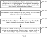
- an embodiment of this application provides a cell installation method, including: disposing a first current collector, a separator, and a second current collector in a stacked manner in a first direction, where the first current collector extends, in a second direction, beyond the separator, and the second direction is perpendicular to the first direction; fastening the first current collector, in the second direction, to a first battery end cover to form a first cell assembly; filling the first cell assembly into a first battery housing, where the first battery housing is a housing with two side openings; and respectively welding the first battery end cover and a second battery end cover at the two side openings of the first battery housing, so that the first cell assembly is disposed inside the first battery housing.
- the fastening the first current collector, in the second direction, to a first battery end cover includes: welding the first current collector, in the second direction, to the first battery end cover.
- This embodiment of this application provides the cell installation method.
- the method includes: disposing the first current collector, the separator, and the second current collector in a stacked manner in the first direction, where the first current collector extends, in the second direction, beyond the separator, and the second direction is perpendicular to the first direction; fastening the first current collector, in the second direction, to the first battery end cover to form the first cell assembly; filling the first cell assembly into the first battery housing, where the first battery housing is the housing with the two side openings; and respectively welding the first battery end cover and the second battery end cover at the two side openings of the first battery housing, so that the first cell assembly is disposed inside the first battery housing.
- the first current collector in a cell of the battery is fastened to the first battery end cover, so that a part of heat generated by the cell can be directly conducted to the first battery end cover through the first current collector. Because thermal conductivity of the current collector is quite high, heat dissipation performance of the cell is improved.
- an embodiment of this application provides a cell installation method.
- the method includes: disposing a first current collector, a separator, and a second current collector in a stacked manner in a first direction, where the first current collector extends, in a second direction, beyond the separator, and the second direction is perpendicular to the first direction; fastening the first current collector, in the second direction, to a heat sink to form a second cell assembly; filling the second cell assembly into a second battery housing, so that the heat sink is in contact with an inner surface of the second battery housing, where the second battery housing is a housing with one side opening; and welding a third battery end cover at the one side opening of the second battery housing, so that the second cell assembly is disposed in a closed manner inside the second battery housing.
- the first current collector is coated with an active substance, and a coating range of the active substance on the first current collector does not extend, in the second direction, beyond the separator.
- This embodiment of this application provides the cell installation method.
- the method includes: disposing the first current collector, the separator, and the second current collector in a stacked manner in the first direction, where the first current collector extends, in the second direction, beyond the separator, and the second direction is perpendicular to the first direction; fastening the first current collector, in the second direction, to the heat sink to form the second cell assembly; filling the second cell assembly into the second battery housing, so that the heat sink is in contact with the inner surface of the second battery housing, where the second battery housing is the housing with the one side opening; and welding the third battery end cover at the one side opening of the second battery housing, so that the second cell assembly is disposed in a closed manner inside the second battery housing.
- the first current collector in a cell of the battery is fastened to the heat sink, so that a part of heat generated by the cell can be directly conducted to the second battery housing through the first current collector and the heat sink. Because thermal conductivity of the current collector and the heat sink is quite high, heat dissipation performance of the cell is improved.
- an embodiment of this application provides a cell installation method.
- the method includes: disposing a first current collector, a separator, and a second current collector in a stacked manner and rolling them by using a third direction as an axis, where the first current collector extends, in the third direction, beyond the separator; fastening the first current collector, in the third direction, to a first battery end cover to form a third cell assembly; filling the third cell assembly into a first battery housing, where the first battery housing is a housing with two side openings; and respectively welding the first battery end cover and a second battery end cover at the two side openings of the first battery housing, so that the third cell assembly is disposed inside the first battery housing.
- This embodiment of this application provides the cell installation method.
- the method includes: disposing the first current collector, the separator, and the second current collector in a stacked manner and rolling them by using the third direction as the axis, where the first current collector extends, in the third direction, beyond the separator; fastening the first current collector, in the third direction, to the first battery end cover to form the third cell assembly; filling the third cell assembly into the first battery housing, where the first battery housing is the housing with the two side openings; and respectively welding the first battery end cover and the second battery end cover at the two side openings of the first battery housing, so that the third cell assembly is disposed inside the first battery housing.
- the first current collector in a cell of the battery is fastened to the first battery end cover, so that a part of heat generated by the cell can be directly conducted to the first battery end cover through the first current collector. Because thermal conductivity of the current collector is quite high, heat dissipation performance of the cell is improved.
- the fastening the first current collector, in the third direction, to a first battery end cover includes: welding the first current collector, in the third direction, to the first battery end cover.
- an embodiment of this application provides a cell installation method.
- the method includes: disposing a first current collector, a separator, and a second current collector in a stacked manner and rolling them by using a third direction as an axis, where the first current collector extends, in the third direction, beyond the separator; fastening the first current collector, in the third direction, to a heat sink to form a fourth cell assembly; filling the fourth cell assembly into a second battery housing, so that the heat sink is in contact with the second battery housing, where the second battery housing is a housing with one side opening; and welding a third battery end cover at the one side opening of the second battery housing, so that the fourth cell assembly is disposed in a closed manner inside the second battery housing.
- the first current collector is coated with an active substance, and a coating range of the active substance on the first current collector does not extend, in the third direction, beyond the separator.
- This embodiment of this application provides the cell installation method.
- the method includes: disposing the first current collector, the separator, and the second current collector in a stacked manner and rolling them by using the third direction as the axis, where the first current collector extends, in the third direction, beyond the separator; fastening the first current collector, in the third direction, to the heat sink to form the fourth cell assembly; filling the fourth cell assembly into the second battery housing, so that the heat sink is in contact with the second battery housing, where the second battery housing is the housing with the one side opening; and welding the third battery end cover at the one side opening of the second battery housing, so that the fourth cell assembly is disposed inside the second battery housing.
- the first current collector in a cell of the battery is fastened to the heat sink, so that a part of heat generated by the cell can be directly conducted to the second battery housing through the first current collector and the heat sink. Because thermal conductivity of the current collector and the heat sink is quite high, heat dissipation performance of the cell is improved.
- the embodiments of this application provide the battery, including the battery housing, the first current collector, the separator, and the second current collector.
- the first current collector, the separator, and the second current collector are stacked and disposed inside the battery housing.
- the polarities of the first current collector and the second current collector are different, and the first current collector is in contact with the battery housing.
- the first current collector in the battery is brought into contact with the battery housing, so that a part of heat generated by the cell can be directly conducted to the battery housing through the first current collector. Because the thermal conductivity of the current collector is quite high, the heat dissipation performance of the cell is improved.
- Embodiments of this application provide a battery, an electrical apparatus, and a cell installation method.
- a first current collector in a battery is brought into contact with a battery housing, so that a part of heat generated by a cell can be directly conducted to the battery housing through the first current collector. Because thermal conductivity of the current collector is quite high, heat dissipation performance of the cell is improved.
- a cell is a core component of an electric automobile. As energy density of the cell and a speed of fast charging increase continuously, a heat dissipation problem of the cell becomes more serious.
- electrical energy is converted into chemical energy and the chemical energy is stored in the cell.
- the chemical energy stored in the cell is converted into electric energy.
- heat is generated inside the cell, and a higher charging or discharging speed leads to more heat generated inside the cell. Consequently, the cell heats up.
- the cell is a temperature sensitive component. When temperature of the cell is excessively high, a lifespan of the cell is shortened seriously, and even there is a risk of an explosion resulting from thermal runaway. Therefore, it is necessary to take effective heat dissipation measures to control the temperature of the cell to be within a proper operating temperature range.
- a positive electrode active substance is coated on a positive electrode current collector to form a positive electrode sheet
- a negative electrode active substance is coated on a negative electrode current collector to form a negative electrode sheet.
- a cell includes the positive electrode sheet, the negative electrode sheet, and a separator.
- the separator is configured to separate the positive electrode sheet from the negative electrode sheet.
- an edge side of the separator extends beyond an edge side of the adjacent positive electrode sheet and an edge side of the adjacent negative electrode sheet.
- the edge side of the separator is in direct contact with an inner surface of the battery housing, and there is a specific air gap between the positive electrode current collector or negative electrode current collector and the battery housing.
- a heat transfer path from an inner part of the cell to the inner surface of the battery housing is from the current collector to the separator or from the current collector to the air gap. Because thermal conductivity of the separator and the air gap is quite low, heat transfer efficiency is quite low, and heat generated inside the cell cannot be quickly conducted to the battery housing.
- an embodiment of this application provides a battery.
- a first current collector in the battery is brought into contact with a battery housing, so that a part of heat generated by a cell in the battery can be directly conducted to the battery housing through the first current collector.
- batteries may be classified into a battery fabricated by using a stacking process (referred to as a stacked battery below) and a battery fabricated by using a jelly-roll process (referred to as a jelly roll battery below).
- a stacking process referred to as a stacked battery below
- a jelly roll battery below a battery fabricated by using a jelly roll battery below
- FIG. 1 is a partial side view of a stacked battery according to an embodiment of this application.
- the battery in this embodiment includes: a battery housing 60, a first current collector 10, a separator 30, and a second current collector 20.
- the first current collector 10, the separator 30, and the second current collector 20 are stacked and disposed inside the battery housing 60. Polarities of the first current collector 10 and the second current collector 20 are different, and the first current collector 10 is in contact with the battery housing 60.
- the first current collector 10, the separator 30, and the second current collector 20 are stacked in a first direction.
- the first current collector 10 extends, in a second direction, beyond the separator 30, and the first current collector 10 may conduct, in the second direction, heat to the battery housing 60 through contact between the first current collector 10 and the battery housing 60.
- the second direction is perpendicular to the first direction.
- the first direction may be a direction perpendicular to a plane on which the first current collector 10 is located, and the second direction may be a direction parallel to the plane on which the first current collector 10 is located.
- the second current collector 20 is correspondingly a negative electrode current collector; or if the first current collector 10 is a negative electrode current collector, the second current collector 20 is correspondingly a positive electrode current collector.
- the battery may further include a battery post 70.
- the first current collector 10 may include four ends, and one of the four ends is connected to the battery post 70.
- an end that is of the first current collector 10 and that conducts heat to the battery housing 60 through contact between the first current collector 10 and the battery housing 60 may be any one or more ends other than the end connected to the battery post 70.
- FIG. 2 is a top view of a stacked battery according to an embodiment of this application.
- An angle of view in FIG. 2 is in a direction perpendicular to the plane on which the first current collector 10 is located.
- the separator 30 is attached to the first current collector 10.
- the first current collector 10 includes four ends (a first end A1, a second end B 1, a second end B2, and a second end B3).
- At least two ends of the second end B1, the second end B2, and the second end B3 of the first current collector 10 may be brought into contact with the battery housing 60.
- the second end B1 and the second end B2 may be brought into contact with the battery housing 60
- the second end B2 and the second end B3 may be brought into contact with the battery housing 60
- all of the second end B 1, the second end B2, and the second end B3 may be brought into contact with the battery housing 60. This is not limited herein.
- the second end B 1, the second end B2, or the second end B3 of the first current collector 10 may be partially extended, to make the second end B 1, the second end B2, or the second end B3 come into contact with the battery housing 60.
- a shape of an extension part of the second end B 1 may be a rectangle, or may be any other shape. This is not limited herein.
- one stacked battery may include a plurality of first current collectors 10.
- the first current collector 10 in contact with the battery housing 60 may be all of the first current collectors 10 in the stacked battery or may be some of all the first current collectors 10.
- a specific first current collector 10 in contact with the battery housing 60 may be selected depending on a requirement. This is not limited herein.
- the separator 30 may not be, in the second direction, in contact with the battery housing 60.
- a first preset distance L1 is reserved, in the second direction, between the separator 30 and the battery housing 60, that is, a specific spacing is reserved, in the second direction, between the separator 30 and the battery housing 60.
- the first current collector 10 extends, in the second direction, beyond the separator 30, that is, a specific spacing is reserved, in the second direction, between the separator 30 and the battery housing 60, and the first current collector 10 is, in the second direction, in contact with the battery housing 60, so that heat radiated from an inner part of a cell is not conducted through the separator 30, but is directly conducted to the battery housing 60 through the first current collector 10 instead. Because thermal conductivity of the current collector is much higher than that of the separator 30, heat dissipation performance of the cell is improved.
- a second preset distance L2 may be reserved, in the second direction, between the second current collector 20 and the battery housing 60.
- the second preset distance L2 is reserved, in the second direction, between the second current collector 20 and the battery housing 60, that is, a specific spacing is reserved between the second current collector 20 and the battery housing 60.
- the second preset distance L2 is reserved, in the second direction, between the second current collector 20 and the battery housing 60, to improve safety of the cell during operation.
- the second preset distance L2 reserved, in the second direction, between the second current collector 20 and the battery housing 60 is greater than the first preset distance L1 reserved, in the second direction, between the separator 30 and the battery housing 60.
- the first current collector 10 extends, in the second direction, beyond the adjacent separator 30.
- the first current collector 10 is detached from the battery housing 60, a part that is of the first current collector 10 and that extends beyond the separator 30 may be bent and then come into contact with the second current collector 20. Consequently, the cell is short-circuited.
- the distance, in the second direction, from the separator 30 to the battery housing 60 is set to be less than the distance from the second current collector 20 to the battery housing 60. Therefore, the separator 30 may act as a barrier between the first current collector 10 and the second current collector 20.
- the first current collector 10 is coated with an active substance 40, and a coating range of the active substance 40 on the first current collector 10 does not extend, in the second direction, beyond the separator 30.
- the second current collector 20 is coated with an active substance 50, and a coating range of the active substance 50 on the second current collector 20 does not extend, in the second direction, beyond the separator 30 either.
- the first current collector 10 is, in the second direction, brought into contact with the battery housing 60, but the second current collector 20 is not brought into contact with the battery housing 60.
- the first current collector 10 extends, in the second direction, beyond the adjacent separator 30. If the active substance 40 is coated on a surface of a part that is of the first current collector 10 and that extends beyond the adjacent separator 30, in an operation process of the cell, the active substance 40 coated on the surface of the part that is of the first current collector 10 and that extends beyond the adjacent separator 30 may come into contact with the adjacent second current collector 20 because of extrusion. This results in a safety problem of a short circuit.
- the coating range of the active substance 40 on the first current collector 10 does not extend, in the second direction, beyond the separator 30.
- the separator 30 acts as a barrier to the active substance 40, so that the active substance on the first current collector 10 does not come into contact with the adjacent second current collector 20 even if extrusion occurs, thereby improving safety of the cell during operation.
- the first current collector 10 is welded to an inner surface of the battery housing 60.
- first current collector 10 a manner of contact between the first current collector 10 and the battery housing 60 is further described.
- one end of the first current collector 10 may be first welded to one battery end cover, and then a component obtained through welding may be filled into the battery housing with two side openings; and the battery end cover may be welded at one side opening of the battery housing, and then the other battery end cover may be welded at the other side opening of the battery housing, to form a closed cavity.
- the first current collector 10 is welded to the inner surface of the battery housing 60 improves solution flexibility and selectivity.
- FIG. 3 is a partial side view of a jelly roll battery according to an embodiment of this application.
- the first current collector, the second current collector, and the separator are sequentially disposed in a stacked manner in a form of a flat plate; in contrast, a separator 30, a first current collector 10, and a second current collector 20used in the jelly-roll process may be rectangular long sheets that are not die-cut into several rectangular sheets, and the first current collector 10, the separator 30, and the second current collector 20 are rolled after being sequentially disposed in a stacked manner, where the first current collector 10 is coated with an active substance 40, and the second current collector is coated with an active substance 50.
- the first current collector 10, the separator 30, and the second current collector 20 are stacked and rolled by using a third direction as an axis.
- the first current collector 10 extends, in the third direction, beyond the separator 30, and the first current collector 10 conducts, in the third direction, heat to the battery housing 60 through contact between the first current collector 10 and the battery housing 60.
- FIG. 4 is a top view of a jelly roll battery according to an embodiment of this application.
- a vertical downward direction in FIG. 4 is the third direction.
- the first current collector 10 extends, in the third direction (a second end B 1), beyond the separator 30, and specifically, the first current collector 10 extends beyond the separator 30 on the second end B 1.
- FIG. 5 is a schematic structural diagram of a first current collector in a jelly roll battery according to an embodiment of this application.
- the first current collector is a rectangular long sheet that has not been rolled.
- the first current collector 10 is coated with the active substance 40, and a region in which no active substance 40 is coated is reserved on the second end B 1 of the first current collector 10, so that a coating range of the active substance 40 on the rolled first current collector 10 does not extend, in the third direction (the second end B 1), beyond the separator 30.
- first current collectors second current collectors
- separators may be determined depending on an actual requirement.
- the battery may further be filled with an electrolyte between the current collector and the separator actually.
- materials of the first current collector 10, the second current collector 20, and the separator 30 in this application are not limited.
- a positive electrode current collector made of aluminum, nickel, copper, or an alloy containing at least one of the foregoing elements is coated with a positive electrode active substance known in the art (for example, lithium manganese oxide, lithium cobalt oxide, lithium nickel oxide, lithium iron phosphate, or a compound or a mixture containing at least one of the foregoing elements).
- a negative electrode current collector made of copper, nickel, aluminum, or an alloy containing at least one of the foregoing elements is coated with a negative electrode active substance known in the art (for example, lithium metal, a lithium alloy, carbon, petroleum coke, activated carbon, graphite, a silicon compound, a tin compound, a titanium compound, or an alloy containing at least one of the foregoing elements).
- a negative electrode active substance known in the art for example, lithium metal, a lithium alloy, carbon, petroleum coke, activated carbon, graphite, a silicon compound, a tin compound, a titanium compound, or an alloy containing at least one of the foregoing elements.
- the separator 30 may be a multilayer film that is of a fine pore structure and is made of polyethylene, polypropylene, or a combination thereof; or may be a polymer film that is used for a solid polymer electrolyte or a gel polymer electrolyte and that is made of polyvinylidene fluoride, polyethylene oxide, polyacrylonitrile, polyvinyl fluoride-hexafluoropropylene copolymer.
- an embodiment of this application provides a battery, including a battery housing 60, a first current collector 10, a separator 30, and a second current collector 20.
- the first current collector 10, the separator 30, and the second current collector 20 are stacked and disposed inside the battery housing 60. Polarities of the first current collector 10 and the second current collector 20 are different, and the first current collector 10 is in contact with the battery housing 60.
- the first current collector 10 in the battery is brought into contact with the battery housing 60, so that a part of heat generated by a cell can be directly conducted to the battery housing 60 through the first current collector 10. Because thermal conductivity of the current collector is quite high, heat dissipation performance of the cell is improved.
- this application further provides an electrical apparatus.
- the electrical apparatus includes at least one battery described in the foregoing embodiments and an electrical load.
- the battery is configured to supply power to the electrical load.
- the electrical apparatus may be a mobile phone, a portable computer, a smartphone, a smart tablet, a netbook, a light electric vehicle, an electric vehicle, a hybrid electric vehicle, or a plug-in hybrid electric vehicle, or may be an electrical storage device or another type of electrical device. This is not limited herein.
- FIG. 6 is a schematic diagram of an embodiment of a cell installation method according to an embodiment of this application. As shown in FIG. 6 , the cell installation method includes the following steps.
- the active substance 40 may first be coated on the first current collector 10, and then the active substance 50 may be coated on the second current collector 20. Refer to FIG. 2 . It should be noted that the active substance 40 may not be coated in an edge region on one side (for example, the second end B 1) that is of the first current collector 10 and that is connected to the battery post 70.
- the first current collector 10 coated with the active substance 40, the separator 30, and the second current collector 20 coated with the active substance 50 need to be disposed in a form of a flat plate in a stacked manner in the first direction to form the cell, and relative locations between the first current collector 10, the separator 30, and the second current collector 20 need to be controlled, to make the first current collector 10 extend, in the second direction, beyond the separator 30.
- the second direction is perpendicular to the first direction.
- quantities of first current collectors 10, separators 30, and second current collectors 20 are not limited in this embodiment.
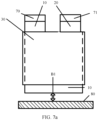
- FIG. 7a is a schematic diagram of a cell installation process according to an embodiment of this application.
- the first current collector 10 extends, in the second direction, beyond the separator 30 (the second end B 1).
- the second end B 1 is fastened to the first battery end cover 80 to form the first cell assembly.
- one side of the first current collector 10 other than the second end B 1 may further be connected to a battery post 70, and correspondingly, the second current collector 20 may further be connected to a battery post 71.
- the first cell assembly in this embodiment may include the first battery end cover 80, the battery post 70, the battery post 71, and the cell that is formed by sequentially disposing the first current collector 10, the separator 30, and the second current collector 20 in a stacked manner.
- the first current collector 10 may be welded, in the second direction, to the first battery end cover 80, or the first current collector 10 may be bonded, in the second direction, to the first battery end cover 80.
- first cell assembly into a first battery housing 81, where the first battery housing 81 is a housing with two side openings.
- first battery end cover 80 and a second battery end cover 82 Respectively weld the first battery end cover 80 and a second battery end cover 82 at the two side openings of the first battery housing 81, so that the first cell assembly is disposed in a closed manner inside the first battery housing 81.
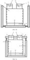
- FIG. 7b is a schematic diagram of a cell installation process according to an embodiment of this application. As shown in FIG. 7b , after fabrication of the first cell assembly is completed, the first cell assembly needs to be assembled into the first battery housing 81.
- two sides of the openings of the first battery housing 81 may be two opposite sides of the housing, for example, may be any two opposite sides of a cuboid.
- Shapes of the first battery end cover 80 and the second battery end cover 82 may respectively coincide with shapes of the two openings of the first battery housing 81.
- the first battery end cover 80 may be welded at one opening of the first battery housing 81.
- FIG. 7c is a schematic diagram of a cell installation process according to an embodiment of this application. As shown in FIG. 7c , after the first battery end cover 80 is welded to one opening of the first battery housing 81, the second battery end cover 82 may be welded at the other opening of the first battery housing 81, to form a closed cavity. In this way, the first cell assembly is disposed in a closed manner inside the first battery housing 81.
- first battery housing 81 with one side opening is used to accommodate the cell, inner surfaces of the first battery housing 81 cannot be strictly perpendicular to each other because of technique limitations. Therefore, one side that is of the first current collector 10 and that extends beyond the separator cannot be welded to an inner surface of the first battery housing 81. If the first battery housing 81 with two side openings is used to accommodate the cell, one side that is of the first current collector 10 and that extends beyond the separator may be first welded to the first battery end cover 80, and then the first battery end cover 80 may be welded to one side opening of the first battery housing 81.
- This embodiment of this application provides the cell installation method.
- the method includes: disposing the first current collector 10, the separator 30, and the second current collector 20 in a stacked manner in the first direction, where the first current collector 10 extends, in the second direction, beyond the separator 30, and the second direction is perpendicular to the first direction; fastening the first current collector 10, in the second direction, to the first battery end cover 80 to form the first cell assembly; filling the first cell assembly into the first battery housing 81, where the first battery housing 81 is the housing with the two side openings; and respectively welding the first battery end cover 80 and the second battery end cover 82 at the two side openings of the first battery housing 81, so that the first cell assembly is disposed inside the first battery housing 81.
- the first current collector 10 in the cell of the battery is fastened to the first battery end cover 80, so that a part of heat generated by the cell can be directly conducted to the first battery end cover 80 through the first current collector 10. Because thermal conductivity of the current collector is quite high, heat dissipation performance of the cell is improved.
- FIG. 8 is a schematic diagram of an embodiment of a cell installation method according to an embodiment of this application. As shown in FIG. 8 , the cell installation method includes the following steps.
- the first current collector 10 coated with the active substance 40, the separator 30, and the second current collector 20 coated with the active substance 50 need to be disposed in a stacked manner and need to be rolled by using the third direction as the axis, to form the cell.
- the third direction is a viewing direction in FIG. 3 .
- the first current collector extends, in the third direction (the second end B 1), beyond the separator.
- step 802 For a specific description of step 802, refer to step 602 in the embodiment corresponding to FIG. 6 . Details are not described herein again.
- step 803 For a specific description of step 803, refer to step 603 in the embodiment corresponding to FIG. 6 . Details are not described herein again.
- first battery end cover 80 and a second battery end cover 82 Respectively weld the first battery end cover 80 and a second battery end cover 82 at the two side openings of the first battery housing 81, so that the third cell assembly is disposed in a closed manner inside the first battery housing 81.
- step 804 For a specific description of step 804, refer to step 604 in the embodiment corresponding to FIG. 6 . Details are not described herein again.
- This embodiment of this application provides the cell installation method.
- the method includes: disposing the first current collector 10, the separator 30, and the second current collector 20 in a stacked manner and rolling them by using the third direction as the axis, where the first current collector 10 extends, in the third direction, beyond the separator 30; fastening the first current collector 10, in the third direction, to the first battery end cover 80 to form the third cell assembly; filling the third cell assembly into the first battery housing 81, where the first battery housing 81 is the housing with the two side openings; and respectively welding the first battery end cover 80 and the second battery end cover 82 at the two side openings of the first battery housing 81, so that the third cell assembly is disposed inside the first battery housing 81.
- the first current collector 10 in the cell of the battery is fastened to the first battery end cover 80, so that a part of heat generated by the cell can be directly conducted to the first battery end cover 80 through the first current collector 10. Because thermal conductivity of the current collector is quite high, heat dissipation performance of the cell is improved.
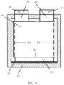
- FIG. 9 is a partial side view of a battery according to an embodiment of this application.
- the battery housing 60 includes: a battery outer casing 61 and a heat sink 62.
- the heat sink 62 is in contact with an inner surface of the battery outer casing 61, and the first current collector 10 is in contact with the heat sink 62.
- the heat sink 62 is a metal sheet with relatively high thermal conductivity.
- the heat sink 62 is in contact with the inner surface of the battery outer casing 61, and the first current collector 10 is fastened to the heat sink 62, so that a part of heat generated by the cell can be directly conducted to the battery outer casing 61 through the first current collector 10 and the heat sink 62. Because thermal conductivity of the current collector and the heat sink 62 is quite high, heat dissipation performance of the cell is improved.
- FIG. 10 is a schematic diagram of an embodiment of a cell installation method according to an embodiment of this application. As shown in FIG. 10 , the cell installation method includes the following steps.
- step 1001 For a specific description of step 1001, refer to step 601 in the embodiment corresponding to FIG. 6 . Details are not described herein again.
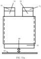
- FIG. 11a is a schematic diagram of a cell installation method according to an embodiment of this application. As shown in FIG. 11a , after the first current collector 10, the separator 30, and the second current collector 20 are disposed in a stacked manner in the first direction to form the cell, the first current collector 10 needs to be fastened, in the second direction, to the heat sink 62 to form the second cell assembly.
- the first current collector is not fastened, in the second direction, to the first battery end cover 80, but is fastened, in the second direction, to the heat sink 62 instead to form the second cell assembly.
- the first current collector is welded, in the second direction, to the heat sink.
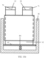
- FIG. 11b is a schematic diagram of a cell installation method according to an embodiment of this application. As shown in FIG. 11b , after the first current collector 10 is fastened, in the second direction, to the heat sink 62 to form the second cell assembly, the second cell assembly needs to be filled into the second battery housing 83, so that the heat sink 62 is in contact with the inner surface of the second battery housing 83.
- FIG. 11c is a schematic diagram of a cell installation method according to an embodiment of this application. As shown in FIG. 11c , after the second cell assembly is filled into the second battery housing, the third battery end cover 84 needs to be welded at the one side opening of the second battery housing 83.
- the first current collector 10 is welded to the heat sink 62 without a need to weld the first current collector 10 to the inner surface of the first battery housing 81, and the heat sink 62 is brought into contact with the inner surface of the second battery housing 83. Therefore, in this embodiment, the second battery housing 83 with the one side opening may be used to accommodate the cell. Compared with the embodiment corresponding to FIG. 6 , a step of welding the first battery end cover 80 to one side opening of the first battery housing 81 is omitted.
- This embodiment of this application provides the cell installation method.
- the method includes: disposing the first current collector 10, the separator 30, and the second current collector 20 in a stacked manner in the first direction, where the first current collector 10 extends, in the second direction, beyond the separator 30, and the second direction is perpendicular to the first direction; fastening the first current collector 10, in the second direction, to the heat sink 62 to form the second cell assembly; filling the second cell assembly into the second battery housing 83, so that the heat sink 62 is in contact with the inner surface of the second battery housing 83, where the second battery housing 83 is the housing with the one side opening; and welding the third battery end cover 84 at the one side opening of the second battery housing 83, so that the second cell assembly is disposed in a closed manner inside the second battery housing 83.
- the first current collector 10 in the cell of the battery is fastened to the heat sink 62, so that a part of heat generated by the cell can be directly conducted to the second battery housing 83 through the first current collector 10 and the heat sink 62. Because thermal conductivity of the current collector and the heat sink 62 is quite high, heat dissipation performance of the cell is improved.
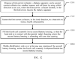
- FIG. 12 is a schematic diagram of an embodiment of a cell installation method according to an embodiment of this application. As shown in FIG. 12 , the cell installation method includes the following steps.
- the first current collector 10 coated with the active substance 40, the separator 30, and the second current collector 20 coated with the active substance 50 need to be disposed in a stacked manner and need to be rolled by using the third direction as the axis, to form the cell.
- the third direction is the viewing direction in FIG. 3 .
- the first current collector extends, in the third direction (the second end B 1), beyond the separator.
- step 1202 For a specific description of step 1202, refer to step 1002 in the embodiment corresponding to FIG. 10 . Details are not described herein again.
- step 1203 For a specific description of step 1203, refer to step 1003 in the embodiment corresponding to FIG. 10 . Details are not described herein again.
- step 1204 For a specific description of step 1204, refer to step 1004 in the embodiment corresponding to FIG. 10 . Details are not described herein again.
- This embodiment of this application provides the cell installation method.
- the method includes: disposing the first current collector 10, the separator 30, and the second current collector 20 in a stacked manner and rolling them by using the third direction as the axis, where the first current collector extends, in the third direction, beyond the separator; fastening the first current collector 10, in the third direction, to the heat sink 62 to form the fourth cell assembly; filling the fourth cell assembly into the second battery housing 83, so that the heat sink 62 is in contact with the second battery housing 83, where the second battery housing 83 is the housing with the one side opening; and welding the third battery end cover 84 at the one side opening of the second battery housing 83, so that the fourth cell assembly is disposed inside the second battery housing 83.
- the first current collector 10 in the cell of the battery is fastened to the heat sink 62, so that a part of heat generated by the cell can be directly conducted to the second battery housing 83 through the first current collector 10 and the heat sink 62. Because thermal conductivity of the current collector and the heat sink 62 is quite high, heat dissipation performance of the cell is improved.
- the disclosed system, apparatus, and method may be implemented in other manners.
- the described apparatus embodiment is merely an example.
- the unit division is merely logical function division and may be other division in actual implementation.
- a plurality of units or components may be combined or integrated into another system, or some features may be ignored or not performed.
- the displayed or discussed mutual couplings, direct couplings, or communication connections may be indirect couplings or communication connections implemented through some interfaces, apparatuses, or units, or may be implemented in electronic, mechanical, or other forms.
Description
- This application relates to the field of power batteries, and in particular, to a battery, an electrical apparatus, and a cell installation method.
- Currently, power batteries, due to their advantages such as high energy density and fast charging, are widely used in scenarios such as electric cars, electric trains, or electric bicycles. In a fast charging process of a power battery, especially a power battery with high energy density, a large amount of heat is generated inside a cell of the power battery. If the heat is not conducted to a battery housing in time, the temperature of the power battery will rise rapidly, and even there is a risk of thermal runaway.
- In the prior art, an end of a separator in the cell extends beyond an adjacent current collector, the separator is in direct contact with the battery housing, and there is a specific air gap between the current collector and the battery housing. In this case, a heat transfer path from an inner part of the cell to the battery housing is from the separator to the battery housing, or from the air gap to the battery housing. Because thermal conductivity of the separator and the air gap is quite low, thermal resistance in the heat transfer path from the inner part of the cell to the battery housing is quite high, which reduces heat dissipation performance of the cell.
US 2017/324125 A1 discloses a battery pack that includes a thermally conductive plate that can be cooled or heated, and an array of electrochemical cells. The cells include a stacked or rolled arrangement of electrode plates, and a current collector disposed in the battery cell that forms an electrical connection with the electrode plates and provides a thermal conduction pathway for conducting heat from the electrode plates to the thermally conductive plate.
CN 109301256 A discloses a lithium ion power battery that includes a cell, an organic case for housing the cell, an electrolyte injected into the organic case and a top cover fixedly connected to the organic case; the cell includes a cathode plate, an anode plate, and a diaphragm therebetween, which are laminated or coiled to make the cell according to the order successively. A heat-conductive heat collector is arranged on the cathode plate and is the local areas, which is not coated with a cathode active material layer, on the front side/or back side of a cathode current collector, wherein at least two mentioned heat-conductive heat collectors are laminated by the same area to form heat confluence channels for heat conduction and collection, thus forming a heat energy input/output heat confluence channel of the cell. The heat confluence channels are stacked or are connected with a fluid channel component. Connection tube ports and connection tubes are arranged on the opposite sides of the organic case in a manner of fluid connection. For single cell case, the numbers of the connection tube ports and connection tubes are equal. The lithium ion power battery effectively solves the problems of excessively high or low temperature.
CN 104882635 A discloses a laminated lithium ion battery, a battery pack comprising the same and a pole piece of the laminated lithium ion battery. The pole piece comprises a current collector and an active material layer, wherein the current collector is coated with the active material layer. A section of continuous uncoated area is arranged at the tail end of a first width end portion of the pole piece, the top face and the bottom face of the uncoated area are not coated with the active material layer, the current collector is exposed in the uncoated area, and the exposed current collector serves as a pole lug of the pole piece. By the pole piece, internal resistance of the lithium ion battery is reduced and heat dissipation performance of the battery is improved.
US 2010/104935 A1 discloses an electrical cell that includes a flat housing, at least one electrode and an electrically and heat conductive tab coupled to the electrode and extending through the housing for electrically and thermally coupling to a collector panel, the tab being capable of conducting both current and a substantial amount of heat out of the housing to a temperature control system. The cells may be stacked to form a battery having a temperature panel interfaced to the temperature control system by a thermal interface. The battery may propel an electrically-powered vehicle or the like.US 2015/064511 A1 discloses a lithium ion battery that includes a cathode in electrical and thermal connection with a cathode current collector. The cathode current collector has an electrode tab. A separator is provided. An anode is in electrical and thermal connection with an anode current collector. The anode current collector has an electrode tab. At least one of the cathode current collector and the anode current collector comprises a thermal tab for heat transfer with the at least one current collector. The thermal tab is separated from the electrode tab. A method of operating a battery is also disclosed.
EP 998 765 A1 - According to a first aspect, an embodiment of this application provides a battery, including a battery housing, a first current collector, a separator, and a second current collector. The first current collector, the separator, and the second current collector are stacked and disposed inside the battery housing. Polarities of the first current collector and the second current collector are different, and the first current collector is in contact with the battery housing.
- This embodiment of this application provides the battery, including the battery housing, the first current collector, the separator, and the second current collector. The first current collector, the separator, and the second current collector are stacked and disposed inside the battery housing. The polarities of the first current collector and the second current collector are different, and the first current collector is in contact with the battery housing. The first current collector in the battery is brought into contact with the battery housing, so that a part of heat generated by a cell can be directly conducted to the battery housing through the first current collector. Because thermal conductivity of the current collector is quite high, heat dissipation performance of the cell is improved.
- According to the invention, the first current collector, the separator, and the second current collector are stacked in a first direction. The first current collector comprises four ends, a first end A1, a second end B 1, a second end B2, and a second end B3. The first current collector extends, in a second direction, beyond the separator, and the first current collector conducts, in the second direction, heat to the battery housing through contact between the first current collector and the battery housing. The second direction is perpendicular to the first direction and at least two ends of the second end B 1, a second end B2, and a second end B3are in contact with the battery housing. The battery in this embodiment is a stacked battery. The first direction is a direction perpendicular to a plane on which the first current collector is located, and the second direction is a direction parallel to the plane on which the first current collector is located. In this embodiment of this application, if the first current collector is a positive electrode current collector, the second current collector is correspondingly a negative electrode current collector; or if the first current collector is a negative electrode current collector, the second current collector is correspondingly a positive electrode current collector. In this embodiment, the first current collector extends, in the second direction, beyond the separator, that is, a specific spacing is reserved, in the second direction, between the separator and the battery housing, and the first current collector is, in the second direction, in contact with the battery housing, so that heat radiated from an inner part of the cell is not conducted through the separator, but is directly conducted to the battery housing through the first current collector instead. Because the thermal conductivity of the current collector is much higher than that of the separator, the heat dissipation performance of the cell is improved.
- In a possible implementation, the first current collector is coated with an active substance, and a coating range of the active substance on the first current collector does not extend, in the second direction, beyond the separator. In this embodiment, to increase thermal conductivity of a heat transfer path from the cell to the battery housing, the first current collector is, in the second direction, brought into contact with the battery housing, but the second current collector is not brought into contact with the battery housing. In this case, the first current collector extends, in the second direction, beyond the adjacent separator. If the active substance is coated on a surface of a part that is of the first current collector and that extends beyond the adjacent separator, in an operation process of the cell, the active substance coated on the surface of the part that is of the first current collector and that extends beyond the adjacent separator may come into contact with the adjacent second current collector because of extrusion. This results in a safety problem of a short circuit. Therefore, in this embodiment, the coating range of the active substance on the first current collector does not extend, in the second direction, beyond the separator. This means that the separator acts as a barrier to the active substance, so that the active substance on the first current collector does not come into contact with the adjacent second current collector even if extrusion occurs, thereby improving safety of the cell during operation.
- In a possible implementation, the first current collector, the separator, and the second current collector are stacked and rolled by using a third direction as an axis. The first current collector extends, in the third direction, beyond the separator, and the first current collector conducts, in the third direction, heat to the battery housing through contact between the first current collector and the battery housing. The battery in this embodiment is a jelly roll battery.
- In a possible implementation, the first current collector is coated with an active substance, and a coating range of the active substance on the first current collector does not extend, in the third direction, beyond the separator. To increase thermal conductivity of a heat transfer path from the cell to the battery housing, in this embodiment, the first current collector is, in the third direction, brought into contact with the battery housing, but the second current collector is not brought into contact with the battery housing. In this case, the first current collector extends, in the third direction, beyond the adjacent separator. If the active substance is coated on a surface of a part that is of the first current collector and that extends beyond the adjacent separator, in an operation process of the cell, the active substance coated on the surface of the part that is of the first current collector and that extends beyond the adjacent separator may come into contact with the adjacent second current collector because of extrusion. This results in a safety problem of a short circuit. Therefore, in this embodiment, the coating range of the active substance on the first current collector does not extend, in the third direction, beyond the separator. This means that the separator acts as a barrier to the active substance, so that the active substance on the first current collector does not come into contact with the adjacent second current collector even if extrusion occurs, thereby improving safety of the cell during operation.
- In a possible implementation, the first current collector is welded to an inner surface of the battery housing. In this embodiment of this application, that the first current collector is welded to the inner surface of the battery housing improves solution flexibility and selectivity.
- In a possible implementation, the battery housing includes a battery outer casing and a heat sink. The heat sink is in contact with an inner surface of the battery outer casing, and the first current collector is in contact with the heat sink.
- In this embodiment, the heat sink is in contact with the inner surface of the battery outer casing, and the first current collector is fastened to the heat sink, so that a part of heat generated by the cell can be directly conducted to the battery outer casing through the first current collector and the heat sink. Because thermal conductivity of the current collector and the heat sink is quite high, the heat dissipation performance of the cell is improved.
- In a possible implementation, the first current collector is welded to the heat sink. In this embodiment of this application, that the first current collector is welded to the heat sink improves solution flexibility and selectivity.
- According to a second aspect, an embodiment of this application provides an electrical apparatus, including an electrical load and at least one battery according to the first aspect. The battery is electrically connected to the electrical load, and the battery is configured to supply power to the electrical load.
- According to a third aspect, an embodiment of this application provides a cell installation method, including:
disposing a first current collector, a separator, and a second current collector in a stacked manner in a first direction, where the first current collector extends, in a second direction, beyond the separator, and the second direction is perpendicular to the first direction; fastening the first current collector, in the second direction, to a first battery end cover to form a first cell assembly; filling the first cell assembly into a first battery housing, where the first battery housing is a housing with two side openings; and respectively welding the first battery end cover and a second battery end cover at the two side openings of the first battery housing, so that the first cell assembly is disposed inside the first battery housing. - In a possible implementation, the fastening the first current collector, in the second direction, to a first battery end cover includes:
welding the first current collector, in the second direction, to the first battery end cover. - This embodiment of this application provides the cell installation method. The method includes: disposing the first current collector, the separator, and the second current collector in a stacked manner in the first direction, where the first current collector extends, in the second direction, beyond the separator, and the second direction is perpendicular to the first direction; fastening the first current collector, in the second direction, to the first battery end cover to form the first cell assembly; filling the first cell assembly into the first battery housing, where the first battery housing is the housing with the two side openings; and respectively welding the first battery end cover and the second battery end cover at the two side openings of the first battery housing, so that the first cell assembly is disposed inside the first battery housing. In a battery fabricated by using the foregoing method, the first current collector in a cell of the battery is fastened to the first battery end cover, so that a part of heat generated by the cell can be directly conducted to the first battery end cover through the first current collector. Because thermal conductivity of the current collector is quite high, heat dissipation performance of the cell is improved.
- According to a fourth aspect, an embodiment of this application provides a cell installation method. The method includes: disposing a first current collector, a separator, and a second current collector in a stacked manner in a first direction, where the first current collector extends, in a second direction, beyond the separator, and the second direction is perpendicular to the first direction; fastening the first current collector, in the second direction, to a heat sink to form a second cell assembly; filling the second cell assembly into a second battery housing, so that the heat sink is in contact with an inner surface of the second battery housing, where the second battery housing is a housing with one side opening; and welding a third battery end cover at the one side opening of the second battery housing, so that the second cell assembly is disposed in a closed manner inside the second battery housing.
- In a possible implementation, the first current collector is coated with an active substance, and a coating range of the active substance on the first current collector does not extend, in the second direction, beyond the separator.
- This embodiment of this application provides the cell installation method. The method includes: disposing the first current collector, the separator, and the second current collector in a stacked manner in the first direction, where the first current collector extends, in the second direction, beyond the separator, and the second direction is perpendicular to the first direction; fastening the first current collector, in the second direction, to the heat sink to form the second cell assembly; filling the second cell assembly into the second battery housing, so that the heat sink is in contact with the inner surface of the second battery housing, where the second battery housing is the housing with the one side opening; and welding the third battery end cover at the one side opening of the second battery housing, so that the second cell assembly is disposed in a closed manner inside the second battery housing. In a battery fabricated by using the foregoing method, the first current collector in a cell of the battery is fastened to the heat sink, so that a part of heat generated by the cell can be directly conducted to the second battery housing through the first current collector and the heat sink. Because thermal conductivity of the current collector and the heat sink is quite high, heat dissipation performance of the cell is improved.
- According to a fifth aspect, an embodiment of this application provides a cell installation method. The method includes: disposing a first current collector, a separator, and a second current collector in a stacked manner and rolling them by using a third direction as an axis, where the first current collector extends, in the third direction, beyond the separator; fastening the first current collector, in the third direction, to a first battery end cover to form a third cell assembly; filling the third cell assembly into a first battery housing, where the first battery housing is a housing with two side openings; and respectively welding the first battery end cover and a second battery end cover at the two side openings of the first battery housing, so that the third cell assembly is disposed inside the first battery housing.
- This embodiment of this application provides the cell installation method. The method includes: disposing the first current collector, the separator, and the second current collector in a stacked manner and rolling them by using the third direction as the axis, where the first current collector extends, in the third direction, beyond the separator; fastening the first current collector, in the third direction, to the first battery end cover to form the third cell assembly; filling the third cell assembly into the first battery housing, where the first battery housing is the housing with the two side openings; and respectively welding the first battery end cover and the second battery end cover at the two side openings of the first battery housing, so that the third cell assembly is disposed inside the first battery housing. In a battery fabricated by using the foregoing method, the first current collector in a cell of the battery is fastened to the first battery end cover, so that a part of heat generated by the cell can be directly conducted to the first battery end cover through the first current collector. Because thermal conductivity of the current collector is quite high, heat dissipation performance of the cell is improved.
- In a possible implementation, the fastening the first current collector, in the third direction, to a first battery end cover includes: welding the first current collector, in the third direction, to the first battery end cover.
- According to a sixth aspect, an embodiment of this application provides a cell installation method. The method includes: disposing a first current collector, a separator, and a second current collector in a stacked manner and rolling them by using a third direction as an axis, where the first current collector extends, in the third direction, beyond the separator; fastening the first current collector, in the third direction, to a heat sink to form a fourth cell assembly; filling the fourth cell assembly into a second battery housing, so that the heat sink is in contact with the second battery housing, where the second battery housing is a housing with one side opening; and welding a third battery end cover at the one side opening of the second battery housing, so that the fourth cell assembly is disposed in a closed manner inside the second battery housing.
- In a possible implementation, the first current collector is coated with an active substance, and a coating range of the active substance on the first current collector does not extend, in the third direction, beyond the separator.
- This embodiment of this application provides the cell installation method. The method includes: disposing the first current collector, the separator, and the second current collector in a stacked manner and rolling them by using the third direction as the axis, where the first current collector extends, in the third direction, beyond the separator; fastening the first current collector, in the third direction, to the heat sink to form the fourth cell assembly; filling the fourth cell assembly into the second battery housing, so that the heat sink is in contact with the second battery housing, where the second battery housing is the housing with the one side opening; and welding the third battery end cover at the one side opening of the second battery housing, so that the fourth cell assembly is disposed inside the second battery housing. In a battery fabricated by using the foregoing method, the first current collector in a cell of the battery is fastened to the heat sink, so that a part of heat generated by the cell can be directly conducted to the second battery housing through the first current collector and the heat sink. Because thermal conductivity of the current collector and the heat sink is quite high, heat dissipation performance of the cell is improved.
- It can be learned from the foregoing technical solutions that, this application has the following advantage:
- The embodiments of this application provide the battery, including the battery housing, the first current collector, the separator, and the second current collector. The first current collector, the separator, and the second current collector are stacked and disposed inside the battery housing. The polarities of the first current collector and the second current collector are different, and the first current collector is in contact with the battery housing. The first current collector in the battery is brought into contact with the battery housing, so that a part of heat generated by the cell can be directly conducted to the battery housing through the first current collector. Because the thermal conductivity of the current collector is quite high, the heat dissipation performance of the cell is improved.
-
-
FIG. 1 is a partial side view of a stacked battery according to an embodiment of this application; -
FIG. 2 is a top view of a stacked battery according to an embodiment of this application; -
FIG. 3 is a partial side view of a jelly roll battery according to an embodiment of this application; -
FIG. 4 is a top view of a jelly roll battery according to an embodiment of this application; -
FIG. 5 is a schematic structural diagram of a first current collector in a jelly roll battery according to an embodiment of this application; -
FIG. 6 is a schematic diagram of an embodiment of a cell installation method according to an embodiment of this application; -
FIG. 7a is a schematic diagram of a cell installation process according to an embodiment of this application; -
FIG. 7b is a schematic diagram of a cell installation process according to an embodiment of this application; -
FIG. 7c is a schematic diagram of a cell installation process according to an embodiment of this application; -
FIG. 8 is a schematic diagram of an embodiment of a cell installation method according to an embodiment of this application; -
FIG. 9 is a partial side view of a battery according to an embodiment of this application; -
FIG. 10 is a schematic diagram of an embodiment of a cell installation method according to an embodiment of this application; -
FIG. 11a is a schematic diagram of a cell installation process according to an embodiment of this application; -
FIG. 11b is a schematic diagram of a cell installation process according to an embodiment of this application; -
FIG. 11c is a schematic diagram of a cell installation process according to an embodiment of this application; and -
FIG. 12 is a schematic diagram of an embodiment of a cell installation method according to an embodiment of this application. - Embodiments of this application provide a battery, an electrical apparatus, and a cell installation method. A first current collector in a battery is brought into contact with a battery housing, so that a part of heat generated by a cell can be directly conducted to the battery housing through the first current collector. Because thermal conductivity of the current collector is quite high, heat dissipation performance of the cell is improved.
- In the specification, claims, and accompanying drawings of this application, the terms "first", "second", "third", "fourth", and so on (if existent) are intended to distinguish between similar objects but do not necessarily indicate a specific order or sequence. It should be understood that the data termed in such a way are interchangeable in proper circumstances so that the embodiments of the present invention described herein can be implemented in orders other than the order illustrated or described herein. Moreover, the terms "include", "contain" and any other variant mean to cover the non-exclusive inclusion, for example, a process, method, system, product, or device that includes a list of steps or units is not necessarily limited to those steps or units, but may include other steps or units not expressly listed or inherent to such a process, method, system, product, or device.
- The following clearly and completely describes the technical solutions in the embodiments of the present invention with reference to the accompanying drawings in the embodiments of the present invention. Apparently, the described embodiments are merely some rather than all of the embodiments of the present invention. All other embodiments obtained by a person skilled in the art based on the embodiments of the present invention without creative efforts shall fall within the protection scope of the present invention.
- A cell is a core component of an electric automobile. As energy density of the cell and a speed of fast charging increase continuously, a heat dissipation problem of the cell becomes more serious. When the electric automobile is charged, electrical energy is converted into chemical energy and the chemical energy is stored in the cell. When the electric automobile travels, the chemical energy stored in the cell is converted into electric energy. In the two energy conversion processes, heat is generated inside the cell, and a higher charging or discharging speed leads to more heat generated inside the cell. Consequently, the cell heats up. The cell is a temperature sensitive component. When temperature of the cell is excessively high, a lifespan of the cell is shortened seriously, and even there is a risk of an explosion resulting from thermal runaway. Therefore, it is necessary to take effective heat dissipation measures to control the temperature of the cell to be within a proper operating temperature range.
- In the prior art, a positive electrode active substance is coated on a positive electrode current collector to form a positive electrode sheet, and a negative electrode active substance is coated on a negative electrode current collector to form a negative electrode sheet. A cell includes the positive electrode sheet, the negative electrode sheet, and a separator. The separator is configured to separate the positive electrode sheet from the negative electrode sheet. Generally, to prevent the positive electrode sheet from being in direct contact with the negative electrode sheet, an edge side of the separator extends beyond an edge side of the adjacent positive electrode sheet and an edge side of the adjacent negative electrode sheet. After the cell is filled into a battery housing, the edge side of the separator is in direct contact with an inner surface of the battery housing, and there is a specific air gap between the positive electrode current collector or negative electrode current collector and the battery housing. In this case, a heat transfer path from an inner part of the cell to the inner surface of the battery housing is from the current collector to the separator or from the current collector to the air gap. Because thermal conductivity of the separator and the air gap is quite low, heat transfer efficiency is quite low, and heat generated inside the cell cannot be quickly conducted to the battery housing.
- To resolve this problem, an embodiment of this application provides a battery. A first current collector in the battery is brought into contact with a battery housing, so that a part of heat generated by a cell in the battery can be directly conducted to the battery housing through the first current collector. The following details an embodiment of the battery provided in this application.
- It can be understood that, based on different fabrication processes, batteries may be classified into a battery fabricated by using a stacking process (referred to as a stacked battery below) and a battery fabricated by using a jelly-roll process (referred to as a jelly roll battery below). The following separately provides specific descriptions.
- Refer to
FIG. 1. FIG. 1 is a partial side view of a stacked battery according to an embodiment of this application. In a scenario in which a firstcurrent collector 10 is a rectangular sheet, as shown inFIG. 1 , the battery in this embodiment includes: abattery housing 60, a firstcurrent collector 10, aseparator 30, and a secondcurrent collector 20. The firstcurrent collector 10, theseparator 30, and the secondcurrent collector 20 are stacked and disposed inside thebattery housing 60. Polarities of the firstcurrent collector 10 and the secondcurrent collector 20 are different, and the firstcurrent collector 10 is in contact with thebattery housing 60. - In this embodiment of this application, the first
current collector 10, theseparator 30, and the secondcurrent collector 20 are stacked in a first direction. The firstcurrent collector 10 extends, in a second direction, beyond theseparator 30, and the firstcurrent collector 10 may conduct, in the second direction, heat to thebattery housing 60 through contact between the firstcurrent collector 10 and thebattery housing 60. The second direction is perpendicular to the first direction. In this embodiment, the first direction may be a direction perpendicular to a plane on which the firstcurrent collector 10 is located, and the second direction may be a direction parallel to the plane on which the firstcurrent collector 10 is located. - In this embodiment of this application, if the first
current collector 10 is a positive electrode current collector, the secondcurrent collector 20 is correspondingly a negative electrode current collector; or if the firstcurrent collector 10 is a negative electrode current collector, the secondcurrent collector 20 is correspondingly a positive electrode current collector. - In this embodiment of this application, the battery may further include a
battery post 70. In a scenario in which the firstcurrent collector 10 is a rectangular sheet, the firstcurrent collector 10 may include four ends, and one of the four ends is connected to thebattery post 70. In this embodiment, an end that is of the firstcurrent collector 10 and that conducts heat to thebattery housing 60 through contact between the firstcurrent collector 10 and thebattery housing 60 may be any one or more ends other than the end connected to thebattery post 70. - Refer to
FIG. 2. FIG. 2 is a top view of a stacked battery according to an embodiment of this application. An angle of view inFIG. 2 is in a direction perpendicular to the plane on which the firstcurrent collector 10 is located. As shown inFIG. 2 , theseparator 30 is attached to the firstcurrent collector 10. The firstcurrent collector 10 includes four ends (a first end A1, a second end B 1, a second end B2, and a second end B3). - According to the embodiments of the invention, at least two ends of the second end B1, the second end B2, and the second end B3 of the first
current collector 10 may be brought into contact with thebattery housing 60. For example, the second end B1 and the second end B2 may be brought into contact with thebattery housing 60, the second end B2 and the second end B3 may be brought into contact with thebattery housing 60, or all of the second end B 1, the second end B2, and the second end B3 may be brought into contact with thebattery housing 60. This is not limited herein. - In another embodiment of this application, the second end B 1, the second end B2, or the second end B3 of the first
current collector 10 may be partially extended, to make the second end B 1, the second end B2, or the second end B3 come into contact with thebattery housing 60. It should be noted that a shape of an extension part of the second end B 1 may be a rectangle, or may be any other shape. This is not limited herein. - In another embodiment of this application, one stacked battery may include a plurality of first
current collectors 10. The firstcurrent collector 10 in contact with thebattery housing 60 may be all of the firstcurrent collectors 10 in the stacked battery or may be some of all the firstcurrent collectors 10. In actual application, a specific firstcurrent collector 10 in contact with thebattery housing 60 may be selected depending on a requirement. This is not limited herein. - In an embodiment of this application, the
separator 30 may not be, in the second direction, in contact with thebattery housing 60. As shown inFIG. 1 , a first preset distance L1 is reserved, in the second direction, between theseparator 30 and thebattery housing 60, that is, a specific spacing is reserved, in the second direction, between theseparator 30 and thebattery housing 60. - In this embodiment, the first
current collector 10 extends, in the second direction, beyond theseparator 30, that is, a specific spacing is reserved, in the second direction, between theseparator 30 and thebattery housing 60, and the firstcurrent collector 10 is, in the second direction, in contact with thebattery housing 60, so that heat radiated from an inner part of a cell is not conducted through theseparator 30, but is directly conducted to thebattery housing 60 through the firstcurrent collector 10 instead. Because thermal conductivity of the current collector is much higher than that of theseparator 30, heat dissipation performance of the cell is improved. - In an embodiment of this application, as shown in
FIG. 1 , a second preset distance L2 may be reserved, in the second direction, between the secondcurrent collector 20 and thebattery housing 60. - In this embodiment, the second preset distance L2 is reserved, in the second direction, between the second
current collector 20 and thebattery housing 60, that is, a specific spacing is reserved between the secondcurrent collector 20 and thebattery housing 60. In this embodiment, when the firstcurrent collector 10 is in contact with thebattery housing 60, if the secondcurrent collector 20 is in contact with thebattery housing 60, the cell may be short-circuited because both the firstcurrent collector 10 and the secondcurrent collector 20 are in contact with thebattery housing 60. Therefore, the second preset distance L2 is reserved, in the second direction, between the secondcurrent collector 20 and thebattery housing 60, to improve safety of the cell during operation. - In this embodiment, optionally, the second preset distance L2 reserved, in the second direction, between the second
current collector 20 and thebattery housing 60 is greater than the first preset distance L1 reserved, in the second direction, between theseparator 30 and thebattery housing 60. - If the first
current collector 10 is in contact with thebattery housing 60 and theseparator 30 is not in direct contact with thebattery housing 60, the firstcurrent collector 10 extends, in the second direction, beyond theadjacent separator 30. In a cell installation process, if the firstcurrent collector 10 is detached from thebattery housing 60, a part that is of the firstcurrent collector 10 and that extends beyond theseparator 30 may be bent and then come into contact with the secondcurrent collector 20. Consequently, the cell is short-circuited. In this embodiment, the distance, in the second direction, from theseparator 30 to thebattery housing 60 is set to be less than the distance from the secondcurrent collector 20 to thebattery housing 60. Therefore, theseparator 30 may act as a barrier between the firstcurrent collector 10 and the secondcurrent collector 20. Even if the firstcurrent collector 10 is detached from thebattery housing 60 in the cell installation process, due to a barrier function of theseparator 30, a possibility that the part that is of the firstcurrent collector 10 and that extends beyond theseparator 30 is bent and then comes into contact with the secondcurrent collector 20 is reduced, thereby improving safety of the cell during operation. - In an embodiment of this application, as shown in
FIG. 1 , the firstcurrent collector 10 is coated with anactive substance 40, and a coating range of theactive substance 40 on the firstcurrent collector 10 does not extend, in the second direction, beyond theseparator 30. It should be noted that the secondcurrent collector 20 is coated with anactive substance 50, and a coating range of theactive substance 50 on the secondcurrent collector 20 does not extend, in the second direction, beyond theseparator 30 either. - To increase thermal conductivity of a heat transfer path from the cell to the battery housing, in this embodiment, the first
current collector 10 is, in the second direction, brought into contact with thebattery housing 60, but the secondcurrent collector 20 is not brought into contact with thebattery housing 60. In this case, the firstcurrent collector 10 extends, in the second direction, beyond theadjacent separator 30. If theactive substance 40 is coated on a surface of a part that is of the firstcurrent collector 10 and that extends beyond theadjacent separator 30, in an operation process of the cell, theactive substance 40 coated on the surface of the part that is of the firstcurrent collector 10 and that extends beyond theadjacent separator 30 may come into contact with the adjacent secondcurrent collector 20 because of extrusion. This results in a safety problem of a short circuit. Therefore, in this embodiment, the coating range of theactive substance 40 on the firstcurrent collector 10 does not extend, in the second direction, beyond theseparator 30. This means that theseparator 30 acts as a barrier to theactive substance 40, so that the active substance on the firstcurrent collector 10 does not come into contact with the adjacent secondcurrent collector 20 even if extrusion occurs, thereby improving safety of the cell during operation. - In an embodiment of this application, the first
current collector 10 is welded to an inner surface of thebattery housing 60. - In this embodiment, a manner of contact between the first
current collector 10 and thebattery housing 60 is further described. In the design of welding the firstcurrent collector 10 to thebattery housing 60, in the cell installation process, one end of the firstcurrent collector 10 may be first welded to one battery end cover, and then a component obtained through welding may be filled into the battery housing with two side openings; and the battery end cover may be welded at one side opening of the battery housing, and then the other battery end cover may be welded at the other side opening of the battery housing, to form a closed cavity. - In this embodiment of this application, that the first
current collector 10 is welded to the inner surface of thebattery housing 60 improves solution flexibility and selectivity. - The foregoing describes one embodiment of the battery that is fabricated by using the stacking process and that is provided in this application, and the following details one embodiment of the battery fabricated by using the jelly-roll process.
FIG. 3 is a partial side view of a jelly roll battery according to an embodiment of this application. It can be understood that, in the battery fabricated by using the stacking process, the first current collector, the second current collector, and the separator are sequentially disposed in a stacked manner in a form of a flat plate; in contrast, aseparator 30, a firstcurrent collector 10, and a second current collector 20used in the jelly-roll process may be rectangular long sheets that are not die-cut into several rectangular sheets, and the firstcurrent collector 10, theseparator 30, and the secondcurrent collector 20 are rolled after being sequentially disposed in a stacked manner, where the firstcurrent collector 10 is coated with anactive substance 40, and the second current collector is coated with anactive substance 50. - In this embodiment, the first
current collector 10, theseparator 30, and the secondcurrent collector 20 are stacked and rolled by using a third direction as an axis. The firstcurrent collector 10 extends, in the third direction, beyond theseparator 30, and the firstcurrent collector 10 conducts, in the third direction, heat to thebattery housing 60 through contact between the firstcurrent collector 10 and thebattery housing 60. -
FIG. 4 is a top view of a jelly roll battery according to an embodiment of this application. A vertical downward direction inFIG. 4 is the third direction. As shown inFIG. 4 , the firstcurrent collector 10 extends, in the third direction (a second end B 1), beyond theseparator 30, and specifically, the firstcurrent collector 10 extends beyond theseparator 30 on the second end B 1. - In an embodiment, refer to
FIG. 5. FIG. 5 is a schematic structural diagram of a first current collector in a jelly roll battery according to an embodiment of this application. As shown inFIG. 5 , the first current collector is a rectangular long sheet that has not been rolled. The firstcurrent collector 10 is coated with theactive substance 40, and a region in which noactive substance 40 is coated is reserved on the second end B 1 of the firstcurrent collector 10, so that a coating range of theactive substance 40 on the rolled firstcurrent collector 10 does not extend, in the third direction (the second end B 1), beyond theseparator 30. - It should be noted that the battery structures shown in
FIG. 1 to FIG. 4 are merely used as examples. In actual application, quantities of first current collectors, second current collectors, and separators may be determined depending on an actual requirement. - It should be noted that, although not shown in
FIG. 1 to FIG. 4 , the battery may further be filled with an electrolyte between the current collector and the separator actually. - It should be noted that materials of the first
current collector 10, the secondcurrent collector 20, and theseparator 30 in this application are not limited. A positive electrode current collector made of aluminum, nickel, copper, or an alloy containing at least one of the foregoing elements is coated with a positive electrode active substance known in the art (for example, lithium manganese oxide, lithium cobalt oxide, lithium nickel oxide, lithium iron phosphate, or a compound or a mixture containing at least one of the foregoing elements). In addition, a negative electrode current collector made of copper, nickel, aluminum, or an alloy containing at least one of the foregoing elements is coated with a negative electrode active substance known in the art (for example, lithium metal, a lithium alloy, carbon, petroleum coke, activated carbon, graphite, a silicon compound, a tin compound, a titanium compound, or an alloy containing at least one of the foregoing elements). Moreover, theseparator 30 may be a multilayer film that is of a fine pore structure and is made of polyethylene, polypropylene, or a combination thereof; or may be a polymer film that is used for a solid polymer electrolyte or a gel polymer electrolyte and that is made of polyvinylidene fluoride, polyethylene oxide, polyacrylonitrile, polyvinyl fluoride-hexafluoropropylene copolymer. - Furthermore, an embodiment of this application provides a battery, including a
battery housing 60, a firstcurrent collector 10, aseparator 30, and a secondcurrent collector 20. The firstcurrent collector 10, theseparator 30, and the secondcurrent collector 20 are stacked and disposed inside thebattery housing 60. Polarities of the firstcurrent collector 10 and the secondcurrent collector 20 are different, and the firstcurrent collector 10 is in contact with thebattery housing 60. The firstcurrent collector 10 in the battery is brought into contact with thebattery housing 60, so that a part of heat generated by a cell can be directly conducted to thebattery housing 60 through the firstcurrent collector 10. Because thermal conductivity of the current collector is quite high, heat dissipation performance of the cell is improved. - Based on the foregoing embodiments, this application further provides an electrical apparatus. The electrical apparatus includes at least one battery described in the foregoing embodiments and an electrical load. The battery is configured to supply power to the electrical load. Specifically, the electrical apparatus may be a mobile phone, a portable computer, a smartphone, a smart tablet, a netbook, a light electric vehicle, an electric vehicle, a hybrid electric vehicle, or a plug-in hybrid electric vehicle, or may be an electrical storage device or another type of electrical device. This is not limited herein.
- The specific structure of the stacked battery is detailed in the embodiment shown in
FIG. 1 andFIG. 2 . With reference to the embodiment shown inFIG. 1 andFIG. 2 , the following details a method for installing the cell in the stacked battery.FIG. 6 is a schematic diagram of an embodiment of a cell installation method according to an embodiment of this application. As shown inFIG. 6 , the cell installation method includes the following steps. - 601. Dispose the first
current collector 10, theseparator 30, and the secondcurrent collector 20 in a stacked manner in the first direction, where the firstcurrent collector 10 extends, in the second direction, beyond theseparator 30, and the second direction is perpendicular to the first direction. - In this embodiment, in a fabrication process of the cell, the
active substance 40 may first be coated on the firstcurrent collector 10, and then theactive substance 50 may be coated on the secondcurrent collector 20. Refer toFIG. 2 . It should be noted that theactive substance 40 may not be coated in an edge region on one side (for example, the second end B 1) that is of the firstcurrent collector 10 and that is connected to thebattery post 70. - In this embodiment, the first
current collector 10 coated with theactive substance 40, theseparator 30, and the secondcurrent collector 20 coated with theactive substance 50 need to be disposed in a form of a flat plate in a stacked manner in the first direction to form the cell, and relative locations between the firstcurrent collector 10, theseparator 30, and the secondcurrent collector 20 need to be controlled, to make the firstcurrent collector 10 extend, in the second direction, beyond theseparator 30. The second direction is perpendicular to the first direction. - It should be noted that, quantities of first
current collectors 10,separators 30, and secondcurrent collectors 20 are not limited in this embodiment. - 602. Fasten the first
current collector 10, in the second direction, to a first battery end cover 80 to form a first cell assembly. - In this embodiment, refer to
FIG. 7a. FIG. 7a is a schematic diagram of a cell installation process according to an embodiment of this application. As shown inFIG. 7a , the firstcurrent collector 10 extends, in the second direction, beyond the separator 30 (the second end B 1). The second end B 1 is fastened to the first battery end cover 80 to form the first cell assembly. It should be noted that one side of the firstcurrent collector 10 other than the second end B 1 may further be connected to abattery post 70, and correspondingly, the secondcurrent collector 20 may further be connected to abattery post 71. The first cell assembly in this embodiment may include the firstbattery end cover 80, thebattery post 70, thebattery post 71, and the cell that is formed by sequentially disposing the firstcurrent collector 10, theseparator 30, and the secondcurrent collector 20 in a stacked manner. - Optionally, the first
current collector 10 may be welded, in the second direction, to the firstbattery end cover 80, or the firstcurrent collector 10 may be bonded, in the second direction, to the firstbattery end cover 80. - 603. Fill the first cell assembly into a
first battery housing 81, where thefirst battery housing 81 is a housing with two side openings. - 604. Respectively weld the first
battery end cover 80 and a second battery end cover 82 at the two side openings of thefirst battery housing 81, so that the first cell assembly is disposed in a closed manner inside thefirst battery housing 81. - In this embodiment, refer to
FIG. 7b. FIG. 7b is a schematic diagram of a cell installation process according to an embodiment of this application. As shown inFIG. 7b , after fabrication of the first cell assembly is completed, the first cell assembly needs to be assembled into thefirst battery housing 81. - In this embodiment, two sides of the openings of the
first battery housing 81 may be two opposite sides of the housing, for example, may be any two opposite sides of a cuboid. Shapes of the firstbattery end cover 80 and the secondbattery end cover 82 may respectively coincide with shapes of the two openings of thefirst battery housing 81. After the first cell assembly is filled into thefirst battery housing 81, the firstbattery end cover 80 may be welded at one opening of thefirst battery housing 81. - Refer to
FIG. 7c. FIG. 7c is a schematic diagram of a cell installation process according to an embodiment of this application. As shown inFIG. 7c , after the firstbattery end cover 80 is welded to one opening of thefirst battery housing 81, the secondbattery end cover 82 may be welded at the other opening of thefirst battery housing 81, to form a closed cavity. In this way, the first cell assembly is disposed in a closed manner inside thefirst battery housing 81. - It should be noted that, if the
first battery housing 81 with one side opening is used to accommodate the cell, inner surfaces of thefirst battery housing 81 cannot be strictly perpendicular to each other because of technique limitations. Therefore, one side that is of the firstcurrent collector 10 and that extends beyond the separator cannot be welded to an inner surface of thefirst battery housing 81. If thefirst battery housing 81 with two side openings is used to accommodate the cell, one side that is of the firstcurrent collector 10 and that extends beyond the separator may be first welded to the firstbattery end cover 80, and then the firstbattery end cover 80 may be welded to one side opening of thefirst battery housing 81. - It can be understood that, in actual application, liquid injection, formation, degassing, liquid injection hole welding, cleaning, and other processing further need to be performed on the assembled battery.
- This embodiment of this application provides the cell installation method. The method includes: disposing the first
current collector 10, theseparator 30, and the secondcurrent collector 20 in a stacked manner in the first direction, where the firstcurrent collector 10 extends, in the second direction, beyond theseparator 30, and the second direction is perpendicular to the first direction; fastening the firstcurrent collector 10, in the second direction, to the first battery end cover 80 to form the first cell assembly; filling the first cell assembly into thefirst battery housing 81, where thefirst battery housing 81 is the housing with the two side openings; and respectively welding the firstbattery end cover 80 and the second battery end cover 82 at the two side openings of thefirst battery housing 81, so that the first cell assembly is disposed inside thefirst battery housing 81. In the battery fabricated by using the foregoing method, the firstcurrent collector 10 in the cell of the battery is fastened to the firstbattery end cover 80, so that a part of heat generated by the cell can be directly conducted to the firstbattery end cover 80 through the firstcurrent collector 10. Because thermal conductivity of the current collector is quite high, heat dissipation performance of the cell is improved. - The specific structure of the jelly roll battery is detailed in the embodiment shown in
FIG. 3 to FIG. 5 . With reference to the embodiment shown inFIG. 3 to FIG. 5 , the following details a method for installing the cell in the jelly roll battery.FIG. 8 is a schematic diagram of an embodiment of a cell installation method according to an embodiment of this application. As shown inFIG. 8 , the cell installation method includes the following steps. - 801. Dispose the first
current collector 10, theseparator 30, and the secondcurrent collector 20 in a stacked manner and roll them by using the third direction as the axis, where the firstcurrent collector 10 extends, in the third direction, beyond theseparator 30. - Refer to
FIG. 3 . It should be noted that, different fromstep 601 in the embodiment corresponding toFIG. 6 , in this embodiment, in a scenario in which the battery is a jelly roll battery, the firstcurrent collector 10 coated with theactive substance 40, theseparator 30, and the secondcurrent collector 20 coated with theactive substance 50 need to be disposed in a stacked manner and need to be rolled by using the third direction as the axis, to form the cell. The third direction is a viewing direction inFIG. 3 . Refer toFIG. 4 . The first current collector extends, in the third direction (the second end B 1), beyond the separator. - 802. Fasten the first
current collector 10, in the third direction, to a first battery end cover 80 to form a third cell assembly. - For a specific description of
step 802, refer to step 602 in the embodiment corresponding toFIG. 6 . Details are not described herein again. - 803. Fill the third cell assembly into a
first battery housing 81, where thefirst battery housing 81 is a housing with two side openings. - For a specific description of
step 803, refer to step 603 in the embodiment corresponding toFIG. 6 . Details are not described herein again. - 804. Respectively weld the first
battery end cover 80 and a second battery end cover 82 at the two side openings of thefirst battery housing 81, so that the third cell assembly is disposed in a closed manner inside thefirst battery housing 81. - For a specific description of
step 804, refer to step 604 in the embodiment corresponding toFIG. 6 . Details are not described herein again. - This embodiment of this application provides the cell installation method. The method includes: disposing the first
current collector 10, theseparator 30, and the secondcurrent collector 20 in a stacked manner and rolling them by using the third direction as the axis, where the firstcurrent collector 10 extends, in the third direction, beyond theseparator 30; fastening the firstcurrent collector 10, in the third direction, to the first battery end cover 80 to form the third cell assembly; filling the third cell assembly into thefirst battery housing 81, where thefirst battery housing 81 is the housing with the two side openings; and respectively welding the firstbattery end cover 80 and the second battery end cover 82 at the two side openings of thefirst battery housing 81, so that the third cell assembly is disposed inside thefirst battery housing 81. In the battery fabricated by using the foregoing method, the firstcurrent collector 10 in the cell of the battery is fastened to the firstbattery end cover 80, so that a part of heat generated by the cell can be directly conducted to the firstbattery end cover 80 through the firstcurrent collector 10. Because thermal conductivity of the current collector is quite high, heat dissipation performance of the cell is improved. - Optionally, based on the embodiments described in
FIG. 1 to FIG. 5 , in an optional embodiment of the battery provided in the embodiments of this application, refer toFIG. 9. FIG. 9 is a partial side view of a battery according to an embodiment of this application. Thebattery housing 60 includes: a batteryouter casing 61 and aheat sink 62. Theheat sink 62 is in contact with an inner surface of the batteryouter casing 61, and the firstcurrent collector 10 is in contact with theheat sink 62. - In an embodiment, the
heat sink 62 is a metal sheet with relatively high thermal conductivity. - In this embodiment, the
heat sink 62 is in contact with the inner surface of the batteryouter casing 61, and the firstcurrent collector 10 is fastened to theheat sink 62, so that a part of heat generated by the cell can be directly conducted to the batteryouter casing 61 through the firstcurrent collector 10 and theheat sink 62. Because thermal conductivity of the current collector and theheat sink 62 is quite high, heat dissipation performance of the cell is improved. - The specific structure of the battery is detailed in the embodiment shown in
FIG. 9 . With reference to the embodiment shown inFIG. 9 , the following details a method for installing the cell in the battery. The method for installing the cell in the stacked battery is first described.FIG. 10 is a schematic diagram of an embodiment of a cell installation method according to an embodiment of this application. As shown inFIG. 10 , the cell installation method includes the following steps. - 1001. Dispose the first
current collector 10, theseparator 30, and the secondcurrent collector 20 in a stacked manner in the first direction, where the firstcurrent collector 10 extends, in the second direction, beyond theseparator 30, and the second direction is perpendicular to the first direction. - For a specific description of
step 1001, refer to step 601 in the embodiment corresponding toFIG. 6 . Details are not described herein again. - 1002. Fasten the first
current collector 10, in the second direction, to theheat sink 62 to form a second cell assembly. - Refer to
FIG. 11a. FIG. 11a is a schematic diagram of a cell installation method according to an embodiment of this application. As shown inFIG. 11a , after the firstcurrent collector 10, theseparator 30, and the secondcurrent collector 20 are disposed in a stacked manner in the first direction to form the cell, the firstcurrent collector 10 needs to be fastened, in the second direction, to theheat sink 62 to form the second cell assembly. - Different from
step 602 in the embodiment corresponding toFIG. 6 , in this embodiment, the first current collector is not fastened, in the second direction, to the firstbattery end cover 80, but is fastened, in the second direction, to theheat sink 62 instead to form the second cell assembly. - In an embodiment, the first current collector is welded, in the second direction, to the heat sink.
- 1003. Fill the second cell assembly into a
second battery housing 83, so that theheat sink 62 is in contact with an inner surface of thesecond battery housing 83, where thesecond battery housing 83 is a housing with one side opening. - In this embodiment, refer to
FIG. 11b. FIG. 11b is a schematic diagram of a cell installation method according to an embodiment of this application. As shown inFIG. 11b , after the firstcurrent collector 10 is fastened, in the second direction, to theheat sink 62 to form the second cell assembly, the second cell assembly needs to be filled into thesecond battery housing 83, so that theheat sink 62 is in contact with the inner surface of thesecond battery housing 83. - 1004. Weld a third battery end cover 84 at the one side opening of the
second battery housing 83, so that the second cell assembly is disposed in a closed manner inside thesecond battery housing 83. - In this embodiment, refer to
FIG. 11c. FIG. 11c is a schematic diagram of a cell installation method according to an embodiment of this application. As shown inFIG. 11c , after the second cell assembly is filled into the second battery housing, the third battery end cover 84 needs to be welded at the one side opening of thesecond battery housing 83. - It should be noted that, different from the embodiment corresponding to
FIG. 6 , the firstcurrent collector 10 is welded to theheat sink 62 without a need to weld the firstcurrent collector 10 to the inner surface of thefirst battery housing 81, and theheat sink 62 is brought into contact with the inner surface of thesecond battery housing 83. Therefore, in this embodiment, thesecond battery housing 83 with the one side opening may be used to accommodate the cell. Compared with the embodiment corresponding toFIG. 6 , a step of welding the first battery end cover 80 to one side opening of thefirst battery housing 81 is omitted. - It can be understood that, in actual application, liquid injection, formation, degassing, liquid injection hole welding, cleaning, and other processing further need to be performed on the assembled battery.
- This embodiment of this application provides the cell installation method. The method includes: disposing the first
current collector 10, theseparator 30, and the secondcurrent collector 20 in a stacked manner in the first direction, where the firstcurrent collector 10 extends, in the second direction, beyond theseparator 30, and the second direction is perpendicular to the first direction; fastening the firstcurrent collector 10, in the second direction, to theheat sink 62 to form the second cell assembly; filling the second cell assembly into thesecond battery housing 83, so that theheat sink 62 is in contact with the inner surface of thesecond battery housing 83, where thesecond battery housing 83 is the housing with the one side opening; and welding the third battery end cover 84 at the one side opening of thesecond battery housing 83, so that the second cell assembly is disposed in a closed manner inside thesecond battery housing 83. In the battery fabricated by using the foregoing method, the firstcurrent collector 10 in the cell of the battery is fastened to theheat sink 62, so that a part of heat generated by the cell can be directly conducted to thesecond battery housing 83 through the firstcurrent collector 10 and theheat sink 62. Because thermal conductivity of the current collector and theheat sink 62 is quite high, heat dissipation performance of the cell is improved. - The following describes the method for installing the cell in the jelly roll battery.
FIG. 12 is a schematic diagram of an embodiment of a cell installation method according to an embodiment of this application. As shown inFIG. 12 , the cell installation method includes the following steps. - 1201. Dispose the first
current collector 10, theseparator 30, and the secondcurrent collector 20 in a stacked manner and roll them by using the third direction as the axis, where the first current collector extends, in the third direction, beyond the separator. - Refer to
FIG. 3 . It should be noted that, different fromstep 1001 in the embodiment corresponding toFIG. 10 , in this embodiment, in a scenario in which the battery is a jelly roll battery, the firstcurrent collector 10 coated with theactive substance 40, theseparator 30, and the secondcurrent collector 20 coated with theactive substance 50 need to be disposed in a stacked manner and need to be rolled by using the third direction as the axis, to form the cell. The third direction is the viewing direction inFIG. 3 . Refer toFIG. 4 . The first current collector extends, in the third direction (the second end B 1), beyond the separator. - 1202. Fasten the first
current collector 10, in the third direction, to theheat sink 62 to form a fourth cell assembly. - For a specific description of
step 1202, refer to step 1002 in the embodiment corresponding toFIG. 10 . Details are not described herein again. - 1203. Fill the fourth cell assembly into a
second battery housing 83, so that theheat sink 62 is in contact with thesecond battery housing 83, where thesecond battery housing 83 is a housing with one side opening. - For a specific description of
step 1203, refer to step 1003 in the embodiment corresponding toFIG. 10 . Details are not described herein again. - 1204. Weld a third battery end cover 84 at the one side opening of the
second battery housing 83, so that the fourth cell assembly is disposed inside thesecond battery housing 83. - For a specific description of
step 1204, refer to step 1004 in the embodiment corresponding toFIG. 10 . Details are not described herein again. - This embodiment of this application provides the cell installation method. The method includes: disposing the first
current collector 10, theseparator 30, and the secondcurrent collector 20 in a stacked manner and rolling them by using the third direction as the axis, where the first current collector extends, in the third direction, beyond the separator; fastening the firstcurrent collector 10, in the third direction, to theheat sink 62 to form the fourth cell assembly; filling the fourth cell assembly into thesecond battery housing 83, so that theheat sink 62 is in contact with thesecond battery housing 83, where thesecond battery housing 83 is the housing with the one side opening; and welding the third battery end cover 84 at the one side opening of thesecond battery housing 83, so that the fourth cell assembly is disposed inside thesecond battery housing 83. In the battery fabricated by using the foregoing method, the firstcurrent collector 10 in the cell of the battery is fastened to theheat sink 62, so that a part of heat generated by the cell can be directly conducted to thesecond battery housing 83 through the firstcurrent collector 10 and theheat sink 62. Because thermal conductivity of the current collector and theheat sink 62 is quite high, heat dissipation performance of the cell is improved. - It may be clearly understood by a person skilled in the art that, for the purpose of convenient and brief description, for a detailed working process of the foregoing system, apparatus, and unit, reference may be made to a corresponding process in the foregoing method embodiments, and details are not described herein again.
- In the several embodiments provided in this application, it should be understood that the disclosed system, apparatus, and method may be implemented in other manners. For example, the described apparatus embodiment is merely an example. For example, the unit division is merely logical function division and may be other division in actual implementation. For example, a plurality of units or components may be combined or integrated into another system, or some features may be ignored or not performed. In addition, the displayed or discussed mutual couplings, direct couplings, or communication connections may be indirect couplings or communication connections implemented through some interfaces, apparatuses, or units, or may be implemented in electronic, mechanical, or other forms.
- The foregoing embodiments are merely intended for describing the technical solutions of this application, but not for limiting scope of the invention defined by the appended claims.
Claims (10)
- A battery, comprising: a battery housing (60), a first current collector (10), a separator (30), and a second current collector (20); andthe first current collector (10), the separator (30), and the second current collector (20) are stacked and disposed inside the battery housing (60), wherein polarities of the first current collector (10) and the second current collector (20) are different, and the first current collector (10) is in contact with the battery housing (60),wherein the first current collector (10), the separator (30), and the second current collector (20) are stacked in a first direction;the first current collector (10) comprises four ends, a first end A1, a second end B1, a second end B2, and a second end B3, andthe first current collector (10) extends, in a second direction, beyond the separator (30), and the first current collector conducts, in the second direction, heat to the battery housing (60) through contact between the first current collector (10) and the battery housing (60), wherein the second direction is perpendicular to the first direction, andat least two ends of the second end B 1, the second end B2, and the second end B3 are in contact with the battery housing (60).
- The battery according to claim 1, wherein the first current collector (10) is coated with an active substance (40), and a coating range of the active substance (40) on the first current collector (10) does not extend, in the second direction, beyond the separator (30).
- The battery according to claim 1, wherein the first current collector (10), the separator (30), and the second current collector (20) are stacked and rolled by using a third direction as an axis; and
the first current collector (10) extends, in the third direction, beyond the separator (30), and the first current collector conducts, in the third direction, heat to the battery housing (60) through contact between the first current collector (10) and the battery housing (60). - The battery according to claim 3, wherein the first current collector (10) is coated with an active substance (40), and a coating range of the active substance (40) on the first current collector (10) does not extend, in the third direction, beyond the separator (30).
- The battery according to any one of claims 1 to 4, wherein the first current collector (10) is welded to an inner surface of the battery housing (60).
- The battery according to any one of claims 1 to 4, wherein the battery housing (60) comprises a battery outer casing (61) and a heat sink (62); and
the heat sink (62) is in contact with an inner surface of the battery outer casing (61), and the first current collector (10) is in contact with the heat sink (62). - The battery according to claim 6, wherein the first current collector (10) is welded to the heat sink (62).
- An electrical apparatus, comprising an electrical load and at least one battery according to any one of claims 1 to 7, wherein the battery is electrically connected to the electrical load, and the battery is configured to supply power to the electrical load.
- A cell installation method, comprising:disposing (601) a first current collector (10), a separator (30), and a second current collector (20) in a stacked manner in a first direction, wherein the first current collector (10) extends, in a second direction, beyond the separator (30), and the second direction is perpendicular to the first direction;fastening (602) the first current collector (10), in the second direction, to a first battery end cover (80) to form a first cell assembly;filling (603) the first cell assembly into a first battery housing (81) to form a battery of anyone of claims 1 to 7, wherein the first battery housing (81) is a housing with two side openings; andrespectively welding (604) the first battery end cover (80) and a second battery end cover (82) at the two side openings of the first battery housing (81), so that a primacy cell assembly is disposed inside the first battery housing (81).
- The cell installation method according to claim 9, wherein the fastening the first current collector (10), in the second direction, to the first battery end cover (80) comprises:
welding the first current collector (10), in the second direction, to the first battery end cover (80).
Applications Claiming Priority (2)
| Application Number | Priority Date | Filing Date | Title |
|---|---|---|---|
| CN201910226392.6A CN110098429B (en) | 2019-03-22 | 2019-03-22 | Battery, power utilization device and battery core installation method |
| PCT/CN2019/127764 WO2020192206A1 (en) | 2019-03-22 | 2019-12-24 | Battery, electrical apparatus and cell installation method |
Publications (3)
| Publication Number | Publication Date |
|---|---|
| EP3933993A1 EP3933993A1 (en) | 2022-01-05 |
| EP3933993A4 EP3933993A4 (en) | 2022-04-20 |
| EP3933993B1 true EP3933993B1 (en) | 2023-06-28 |
Family
ID=67443965
Family Applications (1)
| Application Number | Title | Priority Date | Filing Date |
|---|---|---|---|
| EP19921076.6A Active EP3933993B1 (en) | 2019-03-22 | 2019-12-24 | Battery, electrical apparatus and cell installation method |
Country Status (4)
| Country | Link |
|---|---|
| US (1) | US20220006115A1 (en) |
| EP (1) | EP3933993B1 (en) |
| CN (1) | CN110098429B (en) |
| WO (1) | WO2020192206A1 (en) |
Families Citing this family (3)
| Publication number | Priority date | Publication date | Assignee | Title |
|---|---|---|---|---|
| CN110098429B (en) * | 2019-03-22 | 2021-11-26 | 华为数字能源技术有限公司 | Battery, power utilization device and battery core installation method |
| US20240030518A1 (en) * | 2020-12-10 | 2024-01-25 | Microvast Power Systems Co., Ltd. | Lithium-ion secondary battery and electric vehicle |
| CN113611958A (en) * | 2021-08-03 | 2021-11-05 | 深圳市科信通信技术股份有限公司 | Battery cell and manufacturing method thereof |
Citations (3)
| Publication number | Priority date | Publication date | Assignee | Title |
|---|---|---|---|---|
| EP0998765B1 (en) * | 1997-07-25 | 2008-03-05 | 3M Innovative Properties Company | Thermal management system and method for a solid-state energy storing device |
| US20100104935A1 (en) * | 2008-10-28 | 2010-04-29 | Weston Arthur Hermann | Heat dissipation for large battery packs |
| US20150064511A1 (en) * | 2013-09-03 | 2015-03-05 | Hsin Wang | Thermal management for high-capacity large format li-ion batteries |
Family Cites Families (11)
| Publication number | Priority date | Publication date | Assignee | Title |
|---|---|---|---|---|
| US6908711B2 (en) * | 2002-04-10 | 2005-06-21 | Pacific Lithium New Zealand Limited | Rechargeable high power electrochemical device |
| US8084158B2 (en) * | 2005-09-02 | 2011-12-27 | A123 Systems, Inc. | Battery tab location design and method of construction |
| CN202585660U (en) * | 2012-02-20 | 2012-12-05 | 宁德新能源科技有限公司 | Power battery with winding structure |
| CN203398226U (en) * | 2013-06-09 | 2014-01-15 | 上海卡耐新能源有限公司 | Battery with efficient heat dissipation function |
| CN104882635A (en) * | 2015-05-30 | 2015-09-02 | 深圳市格瑞普电池有限公司 | Laminated lithium ion battery, battery pack comprising same and pole piece of laminated lithium ion battery |
| US11289746B2 (en) * | 2016-05-03 | 2022-03-29 | Bosch Battery Systems Llc | Cooling arrangement for an energy storage device |
| CN109301256A (en) * | 2017-06-28 | 2019-02-01 | 湖南妙盛汽车电源有限公司 | A kind of lithium-ion-power cell |
| CN107482156B (en) * | 2017-08-29 | 2020-11-06 | 江苏英能新能源科技有限公司 | Large single lithium ion battery |
| CN108183281A (en) * | 2017-12-28 | 2018-06-19 | 力神动力电池系统有限公司 | The lithium ion battery of radiator structure is set in a kind of |
| CN109742436B (en) * | 2018-12-03 | 2021-04-20 | 华为技术有限公司 | Battery cell, power battery pack, power utilization device and manufacturing method |
| CN110098429B (en) * | 2019-03-22 | 2021-11-26 | 华为数字能源技术有限公司 | Battery, power utilization device and battery core installation method |
-
2019
- 2019-03-22 CN CN201910226392.6A patent/CN110098429B/en active Active
- 2019-12-24 EP EP19921076.6A patent/EP3933993B1/en active Active
- 2019-12-24 WO PCT/CN2019/127764 patent/WO2020192206A1/en unknown
-
2021
- 2021-09-17 US US17/478,457 patent/US20220006115A1/en active Pending
Patent Citations (3)
| Publication number | Priority date | Publication date | Assignee | Title |
|---|---|---|---|---|
| EP0998765B1 (en) * | 1997-07-25 | 2008-03-05 | 3M Innovative Properties Company | Thermal management system and method for a solid-state energy storing device |
| US20100104935A1 (en) * | 2008-10-28 | 2010-04-29 | Weston Arthur Hermann | Heat dissipation for large battery packs |
| US20150064511A1 (en) * | 2013-09-03 | 2015-03-05 | Hsin Wang | Thermal management for high-capacity large format li-ion batteries |
Also Published As
| Publication number | Publication date |
|---|---|
| WO2020192206A1 (en) | 2020-10-01 |
| CN110098429A (en) | 2019-08-06 |
| EP3933993A1 (en) | 2022-01-05 |
| CN110098429B (en) | 2021-11-26 |
| EP3933993A4 (en) | 2022-04-20 |
| US20220006115A1 (en) | 2022-01-06 |
Similar Documents
| Publication | Publication Date | Title |
|---|---|---|
| EP3136497B1 (en) | Battery module including water cooling structure | |
| CN104285315B (en) | There is the battery module of high-efficient cooling structure | |
| US20220271387A1 (en) | Battery module, battery pack, and vehicle | |
| EP2523249B1 (en) | Mid- or large-sized battery pack having improved cooling efficiency | |
| EP2573861B1 (en) | Cooling member having a novel structure, and battery module including same | |
| EP3182502B1 (en) | Battery pack case having efficient cooling structure | |
| US8043743B2 (en) | Pouch type secondary battery with improved safety | |
| JP4173674B2 (en) | Electrochemical device module | |
| EP2608310A2 (en) | Battery module with compact structure and excellent heat radiation characteristics, and medium- or large-sized battery pack | |
| JP6626577B2 (en) | Battery module, battery pack including the same, and automobile | |
| EP2840644A1 (en) | Battery cell having improved cooling efficiency | |
| EP3933993B1 (en) | Battery, electrical apparatus and cell installation method | |
| EP3678208B1 (en) | Battery module, battery pack, and vehicle | |
| EP3285327B1 (en) | Battery module | |
| KR102618844B1 (en) | Lead tabs for battery terminals | |
| KR20170034560A (en) | Battery Module | |
| CN103119764A (en) | Battery comprising cuboid cells which contain a bipolar electrode | |
| KR102332343B1 (en) | The Battery Module | |
| KR20230051461A (en) | Secondary Battery and Battery Module Having the Same | |
| US11936024B2 (en) | Battery pack, method for producing battery pack and vehicle | |
| JP2020500409A (en) | Battery module | |
| JP2013247024A (en) | Power supply device | |
| US20220021082A1 (en) | Battery module, battery pack, and battery-powered apparatus | |
| US20100143774A1 (en) | Rechargeable battery and electrode assembly | |
| EP3916838A1 (en) | Bus bar module and manufacturing method therefor |
Legal Events
| Date | Code | Title | Description |
|---|---|---|---|
| STAA | Information on the status of an ep patent application or granted ep patent |
Free format text: STATUS: THE INTERNATIONAL PUBLICATION HAS BEEN MADE |
|
| PUAI | Public reference made under article 153(3) epc to a published international application that has entered the european phase |
Free format text: ORIGINAL CODE: 0009012 |
|
| STAA | Information on the status of an ep patent application or granted ep patent |
Free format text: STATUS: REQUEST FOR EXAMINATION WAS MADE |
|
| 17P | Request for examination filed |
Effective date: 20210927 |
|
| AK | Designated contracting states |
Kind code of ref document: A1 Designated state(s): AL AT BE BG CH CY CZ DE DK EE ES FI FR GB GR HR HU IE IS IT LI LT LU LV MC MK MT NL NO PL PT RO RS SE SI SK SM TR |
|
| A4 | Supplementary search report drawn up and despatched |
Effective date: 20220318 |
|
| RIC1 | Information provided on ipc code assigned before grant |
Ipc: H01M 10/6553 20140101ALI20220314BHEP Ipc: H01M 10/6551 20140101ALI20220314BHEP Ipc: H01M 50/102 20210101ALI20220314BHEP Ipc: H01M 10/6554 20140101ALI20220314BHEP Ipc: H01M 10/058 20100101ALI20220314BHEP Ipc: H01M 10/052 20100101ALI20220314BHEP Ipc: H01M 10/654 20140101ALI20220314BHEP Ipc: H01M 10/625 20140101ALI20220314BHEP Ipc: H01M 10/613 20140101ALI20220314BHEP Ipc: H01M 10/04 20060101AFI20220314BHEP |
|
| DAV | Request for validation of the european patent (deleted) | ||
| DAX | Request for extension of the european patent (deleted) | ||
| STAA | Information on the status of an ep patent application or granted ep patent |
Free format text: STATUS: EXAMINATION IS IN PROGRESS |
|
| 17Q | First examination report despatched |
Effective date: 20220914 |
|
| GRAP | Despatch of communication of intention to grant a patent |
Free format text: ORIGINAL CODE: EPIDOSNIGR1 |
|
| STAA | Information on the status of an ep patent application or granted ep patent |
Free format text: STATUS: GRANT OF PATENT IS INTENDED |
|
| INTG | Intention to grant announced |
Effective date: 20230227 |
|
| GRAS | Grant fee paid |
Free format text: ORIGINAL CODE: EPIDOSNIGR3 |
|
| GRAA | (expected) grant |
Free format text: ORIGINAL CODE: 0009210 |
|
| STAA | Information on the status of an ep patent application or granted ep patent |
Free format text: STATUS: THE PATENT HAS BEEN GRANTED |
|
| AK | Designated contracting states |
Kind code of ref document: B1 Designated state(s): AL AT BE BG CH CY CZ DE DK EE ES FI FR GB GR HR HU IE IS IT LI LT LU LV MC MK MT NL NO PL PT RO RS SE SI SK SM TR |
|
| P01 | Opt-out of the competence of the unified patent court (upc) registered |
Effective date: 20230524 |
|
| REG | Reference to a national code |
Ref country code: CH Ref legal event code: EP |
|
| REG | Reference to a national code |
Ref country code: AT Ref legal event code: REF Ref document number: 1583539 Country of ref document: AT Kind code of ref document: T Effective date: 20230715 |
|
| REG | Reference to a national code |
Ref country code: IE Ref legal event code: FG4D |
|
| REG | Reference to a national code |
Ref country code: DE Ref legal event code: R096 Ref document number: 602019031926 Country of ref document: DE |
|
| REG | Reference to a national code |
Ref country code: LT Ref legal event code: MG9D |
|
| PG25 | Lapsed in a contracting state [announced via postgrant information from national office to epo] |
Ref country code: SE Free format text: LAPSE BECAUSE OF FAILURE TO SUBMIT A TRANSLATION OF THE DESCRIPTION OR TO PAY THE FEE WITHIN THE PRESCRIBED TIME-LIMIT Effective date: 20230628 Ref country code: NO Free format text: LAPSE BECAUSE OF FAILURE TO SUBMIT A TRANSLATION OF THE DESCRIPTION OR TO PAY THE FEE WITHIN THE PRESCRIBED TIME-LIMIT Effective date: 20230928 |
|
| REG | Reference to a national code |
Ref country code: NL Ref legal event code: MP Effective date: 20230628 |
|
| REG | Reference to a national code |
Ref country code: AT Ref legal event code: MK05 Ref document number: 1583539 Country of ref document: AT Kind code of ref document: T Effective date: 20230628 |
|
| PG25 | Lapsed in a contracting state [announced via postgrant information from national office to epo] |
Ref country code: RS Free format text: LAPSE BECAUSE OF FAILURE TO SUBMIT A TRANSLATION OF THE DESCRIPTION OR TO PAY THE FEE WITHIN THE PRESCRIBED TIME-LIMIT Effective date: 20230628 Ref country code: NL Free format text: LAPSE BECAUSE OF FAILURE TO SUBMIT A TRANSLATION OF THE DESCRIPTION OR TO PAY THE FEE WITHIN THE PRESCRIBED TIME-LIMIT Effective date: 20230628 Ref country code: LV Free format text: LAPSE BECAUSE OF FAILURE TO SUBMIT A TRANSLATION OF THE DESCRIPTION OR TO PAY THE FEE WITHIN THE PRESCRIBED TIME-LIMIT Effective date: 20230628 Ref country code: LT Free format text: LAPSE BECAUSE OF FAILURE TO SUBMIT A TRANSLATION OF THE DESCRIPTION OR TO PAY THE FEE WITHIN THE PRESCRIBED TIME-LIMIT Effective date: 20230628 Ref country code: HR Free format text: LAPSE BECAUSE OF FAILURE TO SUBMIT A TRANSLATION OF THE DESCRIPTION OR TO PAY THE FEE WITHIN THE PRESCRIBED TIME-LIMIT Effective date: 20230628 Ref country code: GR Free format text: LAPSE BECAUSE OF FAILURE TO SUBMIT A TRANSLATION OF THE DESCRIPTION OR TO PAY THE FEE WITHIN THE PRESCRIBED TIME-LIMIT Effective date: 20230929 |
|
| PG25 | Lapsed in a contracting state [announced via postgrant information from national office to epo] |
Ref country code: FI Free format text: LAPSE BECAUSE OF FAILURE TO SUBMIT A TRANSLATION OF THE DESCRIPTION OR TO PAY THE FEE WITHIN THE PRESCRIBED TIME-LIMIT Effective date: 20230628 |
|
| PG25 | Lapsed in a contracting state [announced via postgrant information from national office to epo] |
Ref country code: SK Free format text: LAPSE BECAUSE OF FAILURE TO SUBMIT A TRANSLATION OF THE DESCRIPTION OR TO PAY THE FEE WITHIN THE PRESCRIBED TIME-LIMIT Effective date: 20230628 |
|
| PGFP | Annual fee paid to national office [announced via postgrant information from national office to epo] |
Ref country code: GB Payment date: 20231102 Year of fee payment: 5 |
|
| PG25 | Lapsed in a contracting state [announced via postgrant information from national office to epo] |
Ref country code: ES Free format text: LAPSE BECAUSE OF FAILURE TO SUBMIT A TRANSLATION OF THE DESCRIPTION OR TO PAY THE FEE WITHIN THE PRESCRIBED TIME-LIMIT Effective date: 20230628 |
|
| PG25 | Lapsed in a contracting state [announced via postgrant information from national office to epo] |
Ref country code: IS Free format text: LAPSE BECAUSE OF FAILURE TO SUBMIT A TRANSLATION OF THE DESCRIPTION OR TO PAY THE FEE WITHIN THE PRESCRIBED TIME-LIMIT Effective date: 20231028 |
|
| PG25 | Lapsed in a contracting state [announced via postgrant information from national office to epo] |
Ref country code: SM Free format text: LAPSE BECAUSE OF FAILURE TO SUBMIT A TRANSLATION OF THE DESCRIPTION OR TO PAY THE FEE WITHIN THE PRESCRIBED TIME-LIMIT Effective date: 20230628 Ref country code: SK Free format text: LAPSE BECAUSE OF FAILURE TO SUBMIT A TRANSLATION OF THE DESCRIPTION OR TO PAY THE FEE WITHIN THE PRESCRIBED TIME-LIMIT Effective date: 20230628 Ref country code: RO Free format text: LAPSE BECAUSE OF FAILURE TO SUBMIT A TRANSLATION OF THE DESCRIPTION OR TO PAY THE FEE WITHIN THE PRESCRIBED TIME-LIMIT Effective date: 20230628 Ref country code: PT Free format text: LAPSE BECAUSE OF FAILURE TO SUBMIT A TRANSLATION OF THE DESCRIPTION OR TO PAY THE FEE WITHIN THE PRESCRIBED TIME-LIMIT Effective date: 20231030 Ref country code: IS Free format text: LAPSE BECAUSE OF FAILURE TO SUBMIT A TRANSLATION OF THE DESCRIPTION OR TO PAY THE FEE WITHIN THE PRESCRIBED TIME-LIMIT Effective date: 20231028 Ref country code: ES Free format text: LAPSE BECAUSE OF FAILURE TO SUBMIT A TRANSLATION OF THE DESCRIPTION OR TO PAY THE FEE WITHIN THE PRESCRIBED TIME-LIMIT Effective date: 20230628 Ref country code: EE Free format text: LAPSE BECAUSE OF FAILURE TO SUBMIT A TRANSLATION OF THE DESCRIPTION OR TO PAY THE FEE WITHIN THE PRESCRIBED TIME-LIMIT Effective date: 20230628 Ref country code: CZ Free format text: LAPSE BECAUSE OF FAILURE TO SUBMIT A TRANSLATION OF THE DESCRIPTION OR TO PAY THE FEE WITHIN THE PRESCRIBED TIME-LIMIT Effective date: 20230628 Ref country code: AT Free format text: LAPSE BECAUSE OF FAILURE TO SUBMIT A TRANSLATION OF THE DESCRIPTION OR TO PAY THE FEE WITHIN THE PRESCRIBED TIME-LIMIT Effective date: 20230628 |
|
| PGFP | Annual fee paid to national office [announced via postgrant information from national office to epo] |
Ref country code: FR Payment date: 20231108 Year of fee payment: 5 Ref country code: DE Payment date: 20231031 Year of fee payment: 5 |
|
| PG25 | Lapsed in a contracting state [announced via postgrant information from national office to epo] |
Ref country code: PL Free format text: LAPSE BECAUSE OF FAILURE TO SUBMIT A TRANSLATION OF THE DESCRIPTION OR TO PAY THE FEE WITHIN THE PRESCRIBED TIME-LIMIT Effective date: 20230628 |