EP4404101A2 - Card-shaped data carrier, semi-finished product and contact layout for same, and method for producing same - Google Patents
Card-shaped data carrier, semi-finished product and contact layout for same, and method for producing same Download PDFInfo
- Publication number
- EP4404101A2 EP4404101A2 EP24180889.8A EP24180889A EP4404101A2 EP 4404101 A2 EP4404101 A2 EP 4404101A2 EP 24180889 A EP24180889 A EP 24180889A EP 4404101 A2 EP4404101 A2 EP 4404101A2
- Authority
- EP
- European Patent Office
- Prior art keywords
- contact
- electronic component
- contact pads
- electrically conductive
- card
- Prior art date
- Legal status (The legal status is an assumption and is not a legal conclusion. Google has not performed a legal analysis and makes no representation as to the accuracy of the status listed.)
- Pending
Links
Images

Classifications
-
- G—PHYSICS
- G06—COMPUTING OR CALCULATING; COUNTING
- G06K—GRAPHICAL DATA READING; PRESENTATION OF DATA; RECORD CARRIERS; HANDLING RECORD CARRIERS
- G06K19/00—Record carriers for use with machines and with at least a part designed to carry digital markings
- G06K19/06—Record carriers for use with machines and with at least a part designed to carry digital markings characterised by the kind of the digital marking, e.g. shape, nature, code
- G06K19/067—Record carriers with conductive marks, printed circuits or semiconductor circuit elements, e.g. credit or identity cards also with resonating or responding marks without active components
- G06K19/07—Record carriers with conductive marks, printed circuits or semiconductor circuit elements, e.g. credit or identity cards also with resonating or responding marks without active components with integrated circuit chips
- G06K19/072—Record carriers with conductive marks, printed circuits or semiconductor circuit elements, e.g. credit or identity cards also with resonating or responding marks without active components with integrated circuit chips the record carrier comprising a plurality of integrated circuit chips
-
- G—PHYSICS
- G06—COMPUTING OR CALCULATING; COUNTING
- G06K—GRAPHICAL DATA READING; PRESENTATION OF DATA; RECORD CARRIERS; HANDLING RECORD CARRIERS
- G06K19/00—Record carriers for use with machines and with at least a part designed to carry digital markings
- G06K19/06—Record carriers for use with machines and with at least a part designed to carry digital markings characterised by the kind of the digital marking, e.g. shape, nature, code
- G06K19/067—Record carriers with conductive marks, printed circuits or semiconductor circuit elements, e.g. credit or identity cards also with resonating or responding marks without active components
- G06K19/07—Record carriers with conductive marks, printed circuits or semiconductor circuit elements, e.g. credit or identity cards also with resonating or responding marks without active components with integrated circuit chips
- G06K19/0716—Record carriers with conductive marks, printed circuits or semiconductor circuit elements, e.g. credit or identity cards also with resonating or responding marks without active components with integrated circuit chips at least one of the integrated circuit chips comprising a sensor or an interface to a sensor
- G06K19/0718—Record carriers with conductive marks, printed circuits or semiconductor circuit elements, e.g. credit or identity cards also with resonating or responding marks without active components with integrated circuit chips at least one of the integrated circuit chips comprising a sensor or an interface to a sensor the sensor being of the biometric kind, e.g. fingerprint sensors
-
- G—PHYSICS
- G06—COMPUTING OR CALCULATING; COUNTING
- G06K—GRAPHICAL DATA READING; PRESENTATION OF DATA; RECORD CARRIERS; HANDLING RECORD CARRIERS
- G06K19/00—Record carriers for use with machines and with at least a part designed to carry digital markings
- G06K19/06—Record carriers for use with machines and with at least a part designed to carry digital markings characterised by the kind of the digital marking, e.g. shape, nature, code
- G06K19/067—Record carriers with conductive marks, printed circuits or semiconductor circuit elements, e.g. credit or identity cards also with resonating or responding marks without active components
- G06K19/07—Record carriers with conductive marks, printed circuits or semiconductor circuit elements, e.g. credit or identity cards also with resonating or responding marks without active components with integrated circuit chips
- G06K19/077—Constructional details, e.g. mounting of circuits in the carrier
- G06K19/0772—Physical layout of the record carrier
Definitions
- the invention relates generally to the field of card-shaped electronic data carriers, in particular chip cards, such as credit and debit cards, and in particular to such data carriers which have two electronic components which are arranged separately in the data carrier but are electrically connected to one another.
- the invention relates to the data carriers as such as well as semi-finished products and contact layouts therefor, and methods for their production.
- the antenna device is laid, for example, as a coil on a layer inside the card, in the so-called card inlay, and has two contact pads that are electrically connected to two corresponding contact surfaces on the underside of a chip module containing the chip.
- the card inlay is laminated with one or more further layers so that the surface of the card inlay that carries the antenna device is inside the card. A cavity is then milled into the card body, into which the chip module is inserted.
- a silicone compound with metallic particles can serve as a connection between the contact pads of the antenna coil and the contact surfaces of the chip module above it. This compound remains elastic after curing and thus forms a reliable connection with the contact surfaces of the chip module placed on top of the silicone compound (so-called flex bump technology).
- an electrically conductive solder paste is applied to the respective contact pad of the antenna device and liquefied in a local melting process so that it creates a reliable electrically conductive connection to the contact surfaces of the chip module, which becomes permanent when the solder cools down (so-called TeConnect method).
- the contact pads of the antenna device are provided with an anisotropically conductive film (ACF). This is a hot-melt plastic material with conductive particles distributed in it, which only conducts electrically perpendicular to the contact pad, so that the film can be applied over a relatively large area, even across several contact pads, without electrically short-circuiting these contact pads (so-called ACF connection technology).
- an electronic card-shaped data carrier can have other electronic components, in particular sensors such as a fingerprint sensor. Such sensors can be used to identify an authorized user and to activate the cards. Like the antenna coil, they must be electrically connected to the chip of the chip card in order to be able to communicate with the chip. This can be done in the same way as previously explained with regard to the antenna device.
- One or more first contact pads of the card inlay for contacting a first electronic component must therefore be electrically connected to one or more second contact pads for contacting a second electronic component.
- the contact pads and the electrically conductive connections between the contact pads are made using one and the same wire to reduce the manufacturing effort, by laying the wire in the area of the contact pads in a meandering or zigzag shape on the card inlay so that the contact pad is sufficiently densely covered with the wire so that contact can be reliably made from above.
- the wire is laid with the help of ultrasound so that it digs into the surface of the card inlay and does not affect the thickness of the card body.
- the wire itself is usually plastic-coated, with the plastic coating in the area of the contact pads being removed during milling.
- the EP 3 159 832 A1 describes an authentication token comprising an authentication module and at least one conductive wire for operatively connecting the authentication module to at least one further module of the token, wherein the at least one conductive wire is embedded in a non-conductive substrate of the token.
- the object of the present invention is therefore to provide a solution in this context as to how, in a card-shaped data carrier with several electronic components that are electrically conductively connected to one another, two contact surfaces of one of these two components and a contact pad of the other component can be electrically conductively connected to one another in a reliable manner.
- a contact layout of a corresponding multilayer card-shaped data carrier can have a first contact pad for connecting a first electronic component and preferably at least two second contact pads for connecting a second electronic component as well as electrically conductive connections on the one hand between the first contact pad and a first of the second contact pads and on the other hand between the first of the second contact pads and a second of the second contact pads.
- the contact pads mentioned are each formed by a meandering wire and are also referred to below as wire pads.
- a continuous wire is used for this purpose, which forms both the contact pads mentioned and the electrically conductive connection.
- This wire is laid in the first of the second contact surfaces as a double meander, namely preferably in such a way that a first part of the wire forms first meander loops lined up in a first direction and an adjoining second part of the continuous wire forms second meander loops lined up in an opposite direction, the first and second meander loops being nested in one another.
- the interlocking forward and backward guidance of the wire laid in a double meander form forms an "interdigital structure".
- a wire path in the wire pad is possible in such a way that the end of the wire running into the contact pad and the end of the wire leading out of the contact pad are at the same end of the contact pad. If the contact pad is then arranged in the card body in such a way that the corresponding opposite end of the contact pad faces the cavity to be milled out, the electrical connection between the first and the second contact pad is not damaged if the double meander-shaped contact pad is milled when the cavity is milled out.
- the contact pads for connecting the first and second electronic components as well as the electrically conductive connections between the contact pads are formed by two continuous wires.
- the first continuous wire forms the (at least one) first contact pad for the first electronic component and the first of the (at least two) two contact pads for the second electronic component as well as a connecting line between these two contact pads.
- the second wire forms the second of the second contact pads and a connecting line leading out of it.
- an electrically conductive connecting element is provided which connects the connecting line formed by the first wire and the second wire is "superimposed" on the connecting line formed by the second wire and is connected to one another in an electrically conductive manner.
- the electrically conductive connecting element can cover the area of the connecting line of the first continuous wire and the area of the connecting line of the second continuous wire from above.
- the electrically conductive connecting element can be provided first on the card inlay and both the laying of the first continuous wire in the area of the connecting line and the laying of the second continuous wire in the area of the connecting line can be carried out over the electrically conductive connecting element, so that the electrically conductive connecting element lies under the continuous wire and the connecting line.
- the electrically conductive connecting element is preferably metallic, in particular copper, and the electrically conductive connection between the electrically conductive connecting element and the connecting line of the first continuous wire on the one hand and between the electrically conductive connecting element and the connecting line of the second continuous wire on the other hand is a welded connection.
- the welded connection is in turn preferably a thermocompression welded connection in which metal is welded to metal by welding the metallic electrically conductive connecting element to the respective wire.
- the thermocompression welding is in turn preferably carried out with the assistance of ultrasound. In the process, both any plastic coating of the wires and any oxide layer of the metallic electrically conductive connecting element are rubbed away before the elements are finally welded together.
- the region of the connecting line of the first continuous wire and the region of the connecting line of the second continuous wire, which are to be connected to one another by means of the electrically conductive connecting element are so close to one another that the electrically conductive connection between the connecting element and the connecting line on the one hand and between the connecting element and the connecting line on the other hand is a common connection point can be formed, in particular as a continuous welded connection, which can advantageously be produced in a single process step, e.g. by thermocompression welding.
- the connecting element is preferably a thin copper element or another electrically conductive element, particularly preferably a metallized film, e.g. a PVC film or another suitable plastic film.
- a third aspect of the present disclosure also provides that the contact pads and the electrically conductive connections therebetween are created by means of two continuous wires.
- the first continuous wire forms the (at least one) first contact pad for the first electronic component and the first of the (at least two) second contact pads for the second electronic component as well as a connecting line between these two contact pads.
- the second wire forms the second of the second contact pads and a connecting line leading out of it.
- the electrically conductive connection is not created by means of an additional electrically conductive connecting element, but instead the first continuous wire forms an additional meandering contact pad in a region of its connecting line, and this additional meandering contact pad overlaps with the connecting line formed by the second wire.
- the electrically conductive connection between the second wire and the first wire in the region of the additional meander-shaped contact pad is again preferably a thermo-compression weld connection in which the wires are welded directly to one another, if necessary again with the assistance of ultrasound.
- the additional contact pad is preferably shifted towards the adjacent contact pad for the second electronic component or towards the adjacent contact pad for the first electronic component, so that these two contact pads together form a large contact pad, which is preferably at least 50% larger than a normal contact pad, in particular than the other contact pad for the second electronic component or than another or all other contact pads for the first electronic component.
- a large contact pad which is preferably at least 50% larger than a normal contact pad, in particular than the other contact pad for the second electronic component or than another or all other contact pads for the first electronic component.
- the additional wire pad can be dispensed with and the connecting line can be directly superimposed on the first of the second contact pads or on the at least one first contact pad, and the electrically conductive connection can be made in the superimposition area.
- Component is formed by an electrically conductive solder material, which preferably connects these two contact pads in a direct line.
- two contact pads for the second electronic component are not electrically connected to one another, but instead two contact surfaces of the electronic component itself are electrically connected.
- the contact layout on the card inlay again comprises a first contact pad for connecting a first electronic component and at least one second contact pad for connecting a second electronic component, as well as an electrically conductive connection between the first contact pad and the second contact pad.
- the contact pads mentioned are preferably each formed by a meandering wire.
- the second electronic component has at least two contact surfaces that are to be short-circuited.
- an electrically conductive connection is provided between the two contact surfaces of the second electronic component by means of an electrically conductive material that is applied to the two contact surfaces and connects them directly to one another. The electrical connection is therefore prefabricated on the electronic component in question before it is inserted into the card body, and is not created on the card inlay.
- This fifth aspect of the present disclosure is particularly suitable for the production of cards in which the contact between the contact pads on the card inlay and the associated contact surfaces of the electronic components is made by means of an anisotropically conductive film (ACF connection technology).
- the electrically conductive material that directly connects the two contact surfaces of the second electronic component is preferably a wire, preferably uninsulated, or alternatively a line of isotropic conductive paste, which may have to harden, or a line of an isotropically conductive plastic.
- the latter alternatives have the advantage that they have less of an impact on the thickness of the card body to be produced.
- the result is in any case a semi-finished product which comprises the contact layout and at least the second electronic component, which are preferably electrically connected to one another by means of an ACF film.
- the contact layout or the surface of the plastic layer on which the contact layout is prepared is ultimately located as a card inlay inside the final multilayer card-shaped data carrier.
- the card inlay layer is laminated with further layers, namely at least one artwork layer covering the contact layout, which is printed with a design and information or provided in another way, and, if the back of the card inlay layer is provided with a similar design or information, preferably a corresponding artwork layer on the back of the card inlay layer.
- a transparent protective layer can be provided on top of each, either as a transparent film or as a transparent protective varnish, in order to form the multilayer card body for the card-shaped data carrier, in which the contact layout and the electronic components electrically connected to one another are integrated.
- a corresponding plurality of areas of a multi-use sheet for example a PVC film
- a suitable metal in particular copper
- a corresponding multi-use sheet namely at least one such metallically coated area per card of the multi-use sheet.
- card-shaped data carriers in particular multilayer card-shaped data carriers, with at least two electronic components, for example a chip card with a conventional chip and one or more electronic components, such as a fingerprint sensor or an iris sensor or other sensors for authenticating a card user.
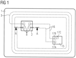
- the Figure 1 such a data carrier schematically in plan view.
- the card body 1 of this chip card contains a coil element 3, which serves as a transmitting and receiving antenna for an integrated circuit of a chip module 2 (not shown in the figure).
- the coil element 3 is in the Figure 1 In the embodiment shown, the coil element 3 is completely embedded in the card body.
- the coil element 3 is Figure 1 shown schematically by a dashed line.
- the chip module 2 is inserted in a recess of the card body and is electrically connected to the coil element 3 via contact surfaces 8 provided on the underside of the chip module 2.
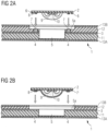
- FIG. 2A shows the Figure 1 shown chip card in a sectional view when inserting the chip module 2 into a two-stage cavity 5 of the card body 1.
- the section was taken along the Figure 1 drawn line AB.
- the card body 1 is multi-layered and comprises at least one card inlay 11 with the coil element 3 arranged thereon including contact pads 4, a cover layer 12, which can be designed as an artwork layer and is accordingly printed on its top side, for example, and optionally transparent protective layers 13A, 13B, which here form the outer layers of the card body.
- the protective layers 13A, 13B can be provided as a lacquer layer or as a film.
- the inlay layer 11 can be on the back just like the cover layer 12 as
- Artwork layer or an additional artwork layer can be provided between the inlay layer 11 and the lower protective layer 13A.
- the film layers 11 and 12 can in turn consist of several individual film layers.
- a two-stage recess 5 with a shoulder area 5a is milled into the card body 1, into which the chip module 2 is inserted from above.
- the chip module 2 is typically fitted into the recess 5 within the applicable technical tolerances so that the surface of the chip module 2 is flush with the surface of the card body 1 and the contact surfaces 8 on the underside of the chip module 2 lie opposite the contact pads 4 of the coil element 3, which have been exposed by milling and partially removed in the process.
- the recess 5 is dimensioned such that it can accommodate the chip module 2 together with a potting compound 9 that surrounds an integrated circuit 10.
- the mechanical connection between the chip module 2 and the card body 1 can be produced, for example, using a thermally activated adhesive 6.
- the electrical connection between the chip module 2 and the coil element 3 contained in the card body 1 can be made by means of a conductive elastomer 7 (e.g. Flex-Bump from Mühlbauer), which is applied to the contact pads 4 of the coil element 3 or, as here, typically to the contact surfaces 8 of the chip module 2.
- a conductive elastomer 7 e.g. Flex-Bump from Mühlbauer
- the conductive elastomer is preferably a silicone mass with metallic particles, which remains elastic after curing and thus forms a reliable electrically conductive connection with the contact surfaces 8 of the chip module 2 resting on the silicone mass from above (so-called flex bump technology).
- an electrically conductive solder paste can be applied to the respective contact pad 4 of the coil element 3 and liquefied in a local melting process so that the solder paste provides a reliable creates an electrically conductive connection to the contact surfaces 8 of the chip module 2, which becomes permanent when the solder cools down (TeConnect process).
- the contact pads 4 of the coil element 3 are provided with an anisotropically conductive foil 7 ⁇ (ACF foil).
- ACF foil anisotropically conductive foil 7 ⁇
- the corresponding card structure is shown in Figure 2B shown.
- the recess is milled down to the wire level 3.
- the ACF film 7 ⁇ is a hot-melt plastic material with conductive particles distributed within it, whereby the film only conducts electricity perpendicular to the contact pad 4, so that the film can be applied over a large area, even across several contact pads 4, without electrically short-circuiting these contact pads 4.
- the ACF film 7 ⁇ is typically applied flatly to the underside of the chip module.
- Figure 1 also shows a further contact surface 17C on the underside of the second electronic component 15, corresponding to the contact surfaces 8 of the chip module 2 in Figure 2A .
- the various aspects described below are concerned with establishing an electrically conductive connection between the contact surfaces 17B and 17C of the second electronic component 15.
- All of the embodiments described below have in common that the contact layout on the inlay layer 11 is formed by wires that are embedded in the surface of the inlay layer 11.
- the wire is laid on the inlay layer and subjected to ultrasound so that it digs into the surface due to the vibrations generated.
- Contact pads of the contact layout are created by laying the wire in a meandering or zigzag manner, and the electrically conductive connections 16 between the contact pads are also formed by the wire from which the pads were made.
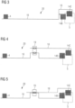
- FIG. 3 schematically shows a part of a contact layout 20 applied to the inlay layer 11 in plan view.
- This part of the contact layout 20 comprises two contact pads 4 and 14B, which are electrically connected by means of the connecting line 16 and are formed by a continuous wire, the wire running in a meandering manner in the area of the contact pads 4 and 14B.
- a third contact pad 14C is present, which is used to contact the in Figure 1 shown contact surface 17C of the second electronic component 15.
- the same wire with which the contact pads 4, 14B and the electrically conductive connection 16 are formed leads from the contact pad 14B to the contact pad 14C and is also laid in a meandering shape there in order to form the contact pad 14C.
- all contact pads 4, 14B, 14C and the connecting lines 16 are formed by a continuous wire.
- the special feature of this aspect of the present disclosure is that the wire is laid as a double meander in the area of the contact pad 14B and preferably leads out on the side of the contact pad 14B where the connecting line 16 leads into the contact pad 14B.
- the contact pads 14B and 14C are located in the shoulder area 5a of the Figure 2B It may happen when milling the two-stage recess, especially in the case of tolerance deviations in card production, that the deeper part of the two-stage recess 5, which is shown in Figure 3 indicated by a frame shown in dashed lines, mills away part of the contact pad 14B.
- the wire in the area of the contact pad 14B is severed and initially no longer leads to the other contact pad 14C.
- this contact pad 14B is subsequently connected to an associated contact surface 17B of the electronic component 15, for example by means of an electrically conductive adhesive or solder or via an electrically conductive ACF foil, then the nested meander loops of the wire laid as a double meander are short-circuited, so that an electrically conductive connection to the contact pad 14C is again established.
- the double meander is preferably laid such that a first part of the continuous wire forms first meander loops arranged in a first direction and an adjoining second part of the continuous wire forms second meander loops arranged in an opposite direction of travel, so that the first and second meander loops are nested in one another.
- the connections 16 to the contact pads 4 and 14C preferably enter the contact pad 14B at locations which are as far away from the recess 5 as possible, preferably on the side of the contact pad 14B facing away from the recess 5.
- the contact layout comprises a first contact pad 4 for connecting a first electronic component, for example the chip module 2, and at least two contact pads 14B, 14C for connecting the second electronic component 15, as well as an electrically conductive connection 16 between the first contact pad 4 and the first of the second contact pads 14B and a further electrically conductive connection 18, 19 between the contact pad 14B and the further contact pad 14C, wherein the contact pads are each formed by a meandering wire.
- the second contact pad 14C is formed by its own continuous wire, which forms a connection line 18 leading out of the contact pad 14C, but which does not lead directly to the first contact pad 14B.
- an electrically conductive connecting element 19 is provided such that it overlays and connects a region of the connecting line 16 between the contact pads 4 and 14B and a region of the connecting line 18.
- the connecting element 19 can be a metallic element or a metallized element, for example a piece of copper or a thin copper foil or a metallized plastic foil, for example a PVC foil, particularly preferably a plastic foil coated with copper. It is possible to first apply the connecting element 19 to the inlay layer 11 and then lay the respective continuous wires in the area of the connecting line 16 and connecting line 18 over it, or to first lay the wires and then place the connecting element 19 over the connecting line 16 and connecting line 18.
- the electrical connections between the electrically conductive connecting element 19 and the connecting line 16 and connecting line 18 are in Fig.4 indicated by two ellipses and are preferably carried out by means of thermocompression welding.
- thermocompression welding is preferably carried out with the assistance of ultrasound, whereby both a plastic coating of the wires and any oxide layer of the metallic electrically conductive connecting element 19 are rubbed away before the elements are finally welded together.
- the embodiments according to Figures 4 and 5 differ only insofar as the connecting line 16 and the connecting line 18 in the embodiment according to Figure 5 are so close together that a single weld (in Fig.5 indicated by only an ellipse) is sufficient to electrically connect both lines 16, 18 to the connecting element 19.
- a separate welded connection is created for the connection of the connecting element 19 with the connecting line 16 on the one hand and with the connecting line 18 on the other hand.
- the electrically conductive connecting elements 19 for a plurality of chip cards on a correspondingly large-format plastic film which forms the inlay layer 11, wherein the electrically conductive connecting elements are provided as a partially metallic coating at the corresponding locations where an electrically conductive connection between adjacent lines 16, 18 is to be established.
- a corresponding number of connecting elements are inserted into prepared cutouts of the full-format sheet, whereupon the wires are then laid.
- a third aspect of the present disclosure is explained below with reference to Figures 6A and 6B explained, which in turn schematically show a part of a contact layout 20 applied to the inlay layer 11 in plan view.
- the solution according to the third aspect is similar to that of the second aspect.
- a fourth wire pad 21 is provided in addition to the connection pads 4, 14B and 14C designed as wire pads, namely as a component of the connecting line 16.
- the connecting lines 16 and the associated wire pads 4, 21 and 14B are formed by means of a continuous wire.
- the connecting line 18 leading out of the connection pad 14C is laid above or below the fourth wire pad 21, depending on which of the two wires is laid first.
- the electrically conductive connection between the connecting line 18 and the fourth wire pad 21 is then made, preferably again by means of thermocompression welding. This is shown in Fig. 6A indicated with an ellipse.
- the advantage of this solution compared to the solution according to the second aspect described above is that no additional material in the sense of another separate element is required to create the connection between the two wires, so that the thickness of the inlay layer 11 with the contact layout 20 located thereon is not increased compared to the double meander solution explained at the beginning.
- Fig. 6B shows an alternative to the embodiment from Fig. 6A such that the additional fourth wire pad 21 is displaced towards the contact pad 14B and preferably forms an enlargement of the contact pad 14B.
- This enlargement is preferably at least 50% and can be as in the embodiment according to Fig. 6B shown is approximately 100%.
- the additional fourth wire pad 21 can be displaced towards the contact pad 4 and preferably form an enlargement of the contact pad 4, so that the contact pad 4 preferably at least 50% and in particular, for example, 100% larger than one or all of the other contact pads 4 for contacting the first electronic component or for contacting the chip module 2.
- Shifting the fourth wire pad 21 to the wire pad 14B or to the wire pad 4 offers the advantage of reducing its visibility on the surface of the finished chip card.
- the fourth wire pad 21 is omitted and the connecting line 18 of the contact pad 14C is laid directly above or below the contact pad 14B, or alternatively above or below the contact pad 4.
- the two wires are electrically connected to one another in the region of the contact pad 14B at approximately the same point at which an electrical connection is later made between the contact pad 14B and the contact connection 17B of the associated second electronic component 15.
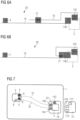
- FIG.7 schematically shows the data carrier 1 in plan view with a first electronic component inserted therein, here the chip module 2, and a second electronic component 15, which is still to be inserted into the two-stage recess 5 of the card body 1.
- the boxes 4 and 17A to 17C shown on the electronic components 2 and 15 represent connection surfaces of the respective electrical components, including the Fig.1 already mentioned connection surface 17C, which together with another connection surface 17B of the same electronic component 15 is to be electrically connected via a connecting line 16 to an associated connection surface 4 of the other electronic component 2.
- connecting lines 16 run inside the card body 1 on an inner surface of an inlay layer.
- the two-stage recess 5 including the shoulder area 5a is milled out of the card body 1, and local depressions are milled in the shoulder area 5a.
- the contact between the contact pads 14A, 14B, 14C on the one hand and the associated contact surfaces 17A, 17B, 17C of the second electronic component 15 on the other hand can be made, for example, in flex bump technology using a solder paste (e.g. TeConnect) or using ACF foil, as also previously explained.
- solder paste e.g. TeConnect
- ACF foil as also previously explained.
- the contact pads 14B and 14C are electrically connected to one another in such a way that the solder paste, or in the case of flex bump technology the electrically conductive plastic mass, is not only applied in the area of the contact pads 14B and 14C, but also that an electrically conductive connection 22 is thereby established directly between the two contact pads 14B and 14C.
- the shoulder region 5a of the second-stage recess 5 is not only milled away in the area of the contact pads 14B and 14C, but a connecting channel is also milled between them, in which the solder paste or the electrically conductive plastic is then laid along a continuous line in order to electrically connect the two contact pads 14B and 14C.
- the solder paste or the electrically conductive plastic is isotropic with respect to electrical conductivity.
- FIG. 8A A fifth aspect of the present disclosure is described below with reference to Figures 8A, 8B and 9 explained.
- the Figures 8A and 8B each schematically shows two embodiments of the second electronic component 15 in a top view. This can be inserted into the card body 1 in the same way as in relation to Fig.7 explained and in Fig.9
- the difference from the fourth aspect described above is that the additional contact pad 14C of the contact layout or the inlay layer can be dispensed with.
- the material for making the conductive connection between the two contact surfaces 17B and 17C of the electronic component 15 in Fig. 8A is a simple, preferably uninsulated wire 23.
- an isotropic conductive paste 24 is provided instead of the wire 23.
- Conductive paste refers to all materials that can be applied in any way to enable an electrical connection between two contact pads.
- This can be, for example, a solder or a paste filled with metallic particles of any shape, as well as carbon or other electrically conductive materials.
- the conductive paste hardens or dries before the electronic component 15 is inserted into the card body 1.
- On the card inlay only a one-to-one wire connection needs to be made between the respective contact pads 4 and 14A, 14B of the electronic components 2 and 15 to be connected to one another, which is preferably again formed by means of a continuous wire that runs in a meandering manner in the area of the contact pads.
- a contact layout for a multilayer card-shaped data carrier for example a chip card, can have at least one first contact pad for connecting a first electronic component and at least two second contact pads for connecting a second electronic component as well as electrically conductive connections on the one hand between the first contact pad and a first of the second contact pads and on the other hand between the first of the second contact pads and a second of the second contact pads, wherein the said contact pads are each formed by a meandering wire, wherein the contact layout can have a continuous wire which forms the said contact pads and the said electrically conductive connections and which is laid in the first of the second contact surfaces as a double meander, preferably in such a way that a first part of the continuous wire forms first meander loops arranged next to one another in a first direction and an adjoining second part of the continuous wire forms second meander loops arranged next to one another in an opposite direction of travel, wherein the first and second meander loops are nested within one another.
- a contact layout for a multilayer card-shaped data carrier for example a chip card, can have at least one first contact pad for connecting a first electronic component and at least two second contact pads for connecting a second electronic component as well as electrically conductive connections on the one hand between the first contact pad and a first of the second contact pads and on the other hand between the first of the second contact pads and a second of the second contact pads, wherein the said contact pads are each formed by a meandering wire, wherein the contact layout can have a first continuous wire which forms the at least one first contact pad and the first of the second contact pads as well as a connecting line between these two contact pads, and a second continuous wire which forms the second of the second contact pads as well as a connecting line leading out from it, wherein a An electrically conductive connecting element overlies a region of the connecting line of the first continuous wire and a region of the connecting line of the second continuous wire and connects them to one another in an electrically conductive manner.
- the electrically conductive connecting element can be metallic and the electrically conductive connection between the electrically conductive connecting element and the connecting line of the first continuous wire on the one hand and between the electrically conductive connecting element and the connecting line of the second continuous wire on the other hand can be a welded connection.
- the welded joint can be a thermo-compression welded joint.
- the region of the connecting line of the first continuous wire and the region of the connecting line of the second continuous wire can be so close to one another that the electrically conductive connection between the electrically conductive connecting element and the connecting line on the one hand and between the electrically conductive connecting element and the connecting line on the other hand is designed as a common connection point.
- the connecting element can be a copper element.
- the connecting element can be a metallized film, preferably a metallized PVC film.
- a contact layout for a multilayer card-shaped data carrier for example a chip card, can have at least one first contact pad for connecting a first electronic component and at least two second contact pads for connecting a second electronic component as well as electrically conductive connections on the one hand between the first contact pad and a first of the second contact pads and on the other hand between the first of the second contact pads and a second of the second contact pads, wherein the said contact pads are each formed by a meandering wire, wherein the contact layout has a first continuous wire which at least a first contact pad and the first of the second contact pads as well as a connecting line between these two contact pads, and a second continuous wire which forms the second of the second contact pads as well as a connecting line leading out therefrom, wherein the first continuous wire forms an additional meander-shaped contact pad in a region of the connecting line, and wherein the additional meander-shaped contact pad formed by the first continuous wire and the connecting line formed by the second continuous wire overlap one another and are electrically conductively connected to one another.
- the additional meander-shaped contact pad can form an enlargement of the first of the second contact pads or of the at least one first contact pad, so that the first of the second contact pads is larger than the second of the second contact pads or the at least one first contact pad is larger than another of the first contact pads.
- the first of the second contact pads can be at least 50% larger than the second of the second contact pads or the at least one first contact pad can be at least 50% larger than the other of the first contact pads.
- the enlargement of the first of the second contact pads formed by the additional meandering contact pad can extend in a direction away from a mounting location of the second electronic component.
- the electrically conductive connection of the connecting cable can be a thermo-compression welded connection with the additional meander-shaped contact pad.
- a contact layout for a multilayer card-shaped data carrier can comprise at least one first contact pad for connecting a first electronic component and at least two second contact pads for connecting a second electronic component, as well as electrically conductive connections on the one hand between the first contact pad and a first of the second contact pads and on the other hand between the first of the second contact pads and a second of the second contact pads, wherein the said contact pads are each formed by a meandering wire, wherein the contact layout can have a first continuous wire which forms the at least one first contact pad and the first of the second contact pads as well as a connecting line between these two contact pads, and a second continuous wire which forms the second of the second contact pads as well as a connecting line leading out therefrom, wherein either the at least one first contact pad or the first of the second contact pads on the one hand and the connecting line formed by the second continuous wire on the other hand overlap one another and are electrically conductively connected to one another.
- the electrically conductive connection of the connecting cable to the at least one first contact pad or the first of the second contact pads can be a thermo-compression welded connection.
- a contact layout for a multilayer card-shaped data carrier for example a chip card
- a semi-finished product for producing a multi-layer card-shaped data carrier can comprise a first electronic component and a second electronic component as well as a plastic layer with a surface which is intended to be and which comprises at least one contact layout, wherein the contact layout can comprise at least a first contact pad for connecting a first electronic component and at least one second contact pad for connecting a second electronic component as well as an electrically conductive connection between the first contact pad and the second contact pad, wherein said contact pads can preferably each be formed by a meandering wire and wherein the second electronic component can have at least two contact surfaces, wherein an electrically conductive connection between the two contact surfaces of the second electronic component is produced by means of an electrically conductive material which is applied to the two contact surfaces and connects them directly to one another.
- the electrically conductive material that directly connects the two contact surfaces of the second electronic component can be an uninsulated wire.
- the electrically conductive material that directly connects the two contact surfaces of the second electronic component can be a line of isotropic conductive paste.
- the semi-finished product can have at least one further second contact pad for connecting the second electronic component, wherein an anisotropically conductive film is provided on the at least two second contact pads for producing an electrically conductive connection with two corresponding contact surfaces of the second electronic component perpendicular to the second contact pads.
- a semi-finished product for producing a multilayer card-shaped data carrier for example a chip card
- the semi-finished product can be a multi-use sheet having several of the contact layouts.
- a multilayer card-shaped data carrier for example a chip card, can have a contact layout as described above or be made from a semi-finished product as described above.
- the data carrier can have at least one cover layer covering the contact layout with at least one recess for receiving the first or the second or both electronic components.
- the at least one recess may be a two-stage recess with a shoulder region extending over at least one of the contact pads of the contact layout.
- the data carrier can have a fingerprint sensor as one of the two electronic components and a microchip electrically connected to it.
- the connecting cable and the connection cable in the area of the electrically conductive connecting element can be laid so close to each other that the electrically conductive connection between the electrically conductive connecting element and the connecting cable on the one hand and between the electrically conductive connecting element and the connecting cable on the other hand is formed as a common connection point.
- the additional meander-shaped contact pad can be designed as an enlargement of the first of the second contact pads or of the at least one first contact pad, so that the first of the second contact pads is larger than the second of the second contact pads or the at least one first contact pad is larger than another of the first contact pads, wherein the first of the second contact pads is preferably 50% is formed larger than the second of the second contact pads or the at least one first contact pad is preferably formed at least 50% larger than the other of the first contact pads.
- the enlargement of the first of the second contact pads formed by the additional meandering contact pad can extend in a direction away from a mounting location of the second electronic component.
- the step of electrically conductive connection can be carried out by thermo-compression welding.
- the step of electrically conductive connection can be carried out by thermo-compression welding.
- the electrically conductive material that directly connects the two contact surfaces of the second electronic component can be an uninsulated wire.
- the electrically conductive material that directly connects the two contact surfaces of the second electronic component can be a line of isotropic conductive paste.
- At least one further second contact pad can be provided for connecting the second electronic component on the plastic substrate, and an anisotropically conductive film can be applied to the at least two second contact pads for producing an electrically conductive connection formed perpendicular to the second contact pads with two corresponding contact surfaces of the second electronic component.
- the plastic film can form a multi-use sheet on which a plurality of the first contact pads and the second contact pads are produced for a variety of contact layouts.
- an inner surface of a layer of the data carrier can be provided with a contact layout according to a method described above.
Landscapes
- Engineering & Computer Science (AREA)
- Computer Hardware Design (AREA)
- Microelectronics & Electronic Packaging (AREA)
- Physics & Mathematics (AREA)
- General Physics & Mathematics (AREA)
- Theoretical Computer Science (AREA)
- Automation & Control Theory (AREA)
- Credit Cards Or The Like (AREA)
Abstract
Es werde Halbzeug zur Herstellung eines mehrschichtigen kartenförmigen Datenträgers vorgeschlagen, beispielsweise einer Chipkarte, umfassend eine erste elektronische Komponente und eine zweite elektronische Komponente sowie eine Kunststoffschicht mit einer Oberfläche, die dazu vorgesehen ist im Inneren des kartenförmigen Datenträgers zu liegen und die mindestens ein Kontaktlayout umfasst. Das Kontaktlayout kann mindestens ein erstes Kontaktpad zum Anschließen einer ersten elektronischen Komponente und mindestens ein zweites Kontaktpad zum Anschließen einer zweiten elektronischen Komponente sowie eine elektrisch leitende Verbindung zwischen dem ersten Kontaktpad und dem zweiten Kontaktpad umfassen. Die genannten Kontaktpads können vorzugsweise jeweils durch einen mäanderförmig verlaufenden Draht gebildet sein und die zweite elektronische Komponente kann mindestens zwei Kontaktflächen aufweisen. Eine elektrisch leitende Verbindung kann zwischen den beiden Kontaktflächen der zweiten elektronischen Komponente mittels eines elektrisch leitenden Materials hergestellt sein, welches auf die beiden Kontaktflächen aufgebracht ist und diese direkt miteinander verbindet.A semi-finished product is proposed for producing a multilayer card-shaped data carrier, for example a chip card, comprising a first electronic component and a second electronic component as well as a plastic layer with a surface that is intended to lie inside the card-shaped data carrier and that comprises at least one contact layout. The contact layout can comprise at least one first contact pad for connecting a first electronic component and at least one second contact pad for connecting a second electronic component as well as an electrically conductive connection between the first contact pad and the second contact pad. The contact pads mentioned can preferably each be formed by a meandering wire and the second electronic component can have at least two contact surfaces. An electrically conductive connection can be made between the two contact surfaces of the second electronic component by means of an electrically conductive material that is applied to the two contact surfaces and connects them directly to one another.
Description
Die Erfindung betrifft allgemein das Gebiet kartenförmiger elektronischer Datenträger, insbesondere Chipkarten, wie beispielsweise Kredit- und Debitkarten, und im Besonderen solche Datenträger, welche zwei elektronische Komponenten aufweisen, die zwar separat im Datenträger angeordnet aber elektrisch miteinander verbunden sind. In diesem Zusammenhang betrifft die Erfindung die Datenträger als solche sowie Halbzeuge und Kontaktlayouts dafür, und Verfahren zu deren Herstellung.The invention relates generally to the field of card-shaped electronic data carriers, in particular chip cards, such as credit and debit cards, and in particular to such data carriers which have two electronic components which are arranged separately in the data carrier but are electrically connected to one another. In this context, the invention relates to the data carriers as such as well as semi-finished products and contact layouts therefor, and methods for their production.
Es ist im Zusammenhang mit kontaktlos kommunizierenden Chipkarten bekannt, den elektronischen Chip ("Microchip") der Chipkarte mit einer im inneren der Chipkarte angeordneten Antennenvorrichtung auszustatten. Dazu ist die Antennenvorrichtung beispielsweise als Spule auf einer im inneren der Karte liegenden Schicht, im sogenannten Karteninlay, verlegt und besitzt zwei Kontaktpads, die mit zwei korrespondierenden Kontaktflächen auf der Unterseite eines den Chip enthaltenden Chipmoduls elektrisch leitend verbunden sind. Zur Herstellung des Kontakts zwischen den Kontaktpads der Antennenspule und den Kontaktflächen des Chipmoduls gibt es verschiedene technische Lösungen. Vielen dieser Lösungen ist gemein, dass das Karteninlay mit einer oder mehreren weiteren Schichten laminiert wird, so dass die die Antennenvorrichtung tragende Oberfläche des Karteninlays im Karteninneren liegt. Anschließend wird eine Kavität in den Kartenkörper gefräst, in welche das Chipmodul eingesetzt wird. Dies ist insbesondere bei sogenannten Dual-Interface-Karten der Fall, bei denen der Chip sowohl kontaktlos über die Antennenvorrichtung, als auch kontaktbehaftet über weitere freiliegende Kontaktflächen des Chipmoduls kommunizieren kann. Bei der Erzeugung der Kavität werden auch die Anschlusspads der Antennenspule freigelegt. Als Verbindung zwischen den Kontaktpads der Antennenspule und den darüber liegenden Kontaktflächen des Chipmoduls kann eine Silikonmasse mit metallischen Partikeln dienen, die nach dem Aushärten elastisch bleibt und dadurch eine zuverlässige Verbindung mit den von oben auf die Silikonmasse aufgesetzten Kontaktflächen des Chipmoduls bildet (sogenannte Flex-Bump-Technologie).In connection with contactless communication chip cards, it is known to equip the electronic chip ("microchip") of the chip card with an antenna device arranged inside the chip card. For this purpose, the antenna device is laid, for example, as a coil on a layer inside the card, in the so-called card inlay, and has two contact pads that are electrically connected to two corresponding contact surfaces on the underside of a chip module containing the chip. There are various technical solutions for establishing contact between the contact pads of the antenna coil and the contact surfaces of the chip module. Many of these solutions have in common that the card inlay is laminated with one or more further layers so that the surface of the card inlay that carries the antenna device is inside the card. A cavity is then milled into the card body, into which the chip module is inserted. This is particularly the case with so-called dual interface cards, where the chip can communicate both contactlessly via the antenna device and with contact via other exposed contact surfaces of the chip module. When the cavity is created, the connection pads of the antenna coil are also exposed. A silicone compound with metallic particles can serve as a connection between the contact pads of the antenna coil and the contact surfaces of the chip module above it. This compound remains elastic after curing and thus forms a reliable connection with the contact surfaces of the chip module placed on top of the silicone compound (so-called flex bump technology).
Gemäß einem alternativen Verfahren wird anstelle der Silikonmasse eine elektrisch leitende Lotpaste auf das jeweilige Kontaktpad der Antennenvorrichtung aufgebracht und in einem lokalen Aufschmelzverfahren verflüssigt, so dass sie eine zuverlässige elektrisch leitende Verbindung zu den Kontaktflächen des Chipmoduls herstellt, welche durch Abkühlen des Lots dauerhaft wird (sogenanntes TeConnect-Verfahren). Gemäß einem dritten Verfahren werden die Kontaktpads der Antennenvorrichtung mit einer anisotrop leitenden Folie (ACF) versehen. Dabei handelt es sich um ein heißschmelzfähiges Kunststoffmaterial mit darin verteilten leitfähigen Partikeln, das nur lotrecht zum Kontaktpad elektrisch leitet, so dass die Folie relativ großflächig auch über mehrere Kontaktpads hinweg aufgebracht werden kann, ohne diese Kontaktpads elektrisch kurzzuschließen (sogenannte ACF-Anschlusstechnik).According to an alternative method, instead of the silicone mass, an electrically conductive solder paste is applied to the respective contact pad of the antenna device and liquefied in a local melting process so that it creates a reliable electrically conductive connection to the contact surfaces of the chip module, which becomes permanent when the solder cools down (so-called TeConnect method). According to a third method, the contact pads of the antenna device are provided with an anisotropically conductive film (ACF). This is a hot-melt plastic material with conductive particles distributed in it, which only conducts electrically perpendicular to the contact pad, so that the film can be applied over a relatively large area, even across several contact pads, without electrically short-circuiting these contact pads (so-called ACF connection technology).
Anstelle der Antennenvorrichtung oder vielfach in Ergänzung dazu, kann ein elektronischer kartenförmiger Datenträger weitere elektronische Komponenten aufweisen, insbesondere Sensoren wie beispielsweise einen Fingerabdrucksensor Solche Sensoren können zur Identifizierung eines berechtigen Benutzers und zum Freischalten der Karten dienen. Sie müssen genauso wie die Antennenspule mit dem Chip der Chipkarte elektrisch leitend verbunden werden, um mit dem Chip kommunizieren zu können. Dies kann in derselben Weise geschehen, wie zuvor in Bezug auf die Antennenvorrichtung erläutert.Instead of the antenna device or often in addition to it, an electronic card-shaped data carrier can have other electronic components, in particular sensors such as a fingerprint sensor. Such sensors can be used to identify an authorized user and to activate the cards. Like the antenna coil, they must be electrically connected to the chip of the chip card in order to be able to communicate with the chip. This can be done in the same way as previously explained with regard to the antenna device.
Es sind also ein oder mehrere erste Kontaktpads des Karteninlays zur Kontaktierung einer ersten elektronischen Komponente mit ein oder mehreren zweiten Kontaktpads zur Kontaktierung einer zweiten elektronischen Komponente elektrisch leitend zu verbinden. Anstatt jeweils vollflächige Kontaktpads vorzusehen, die mittels separater Leitungen individuell miteinander verbunden werden, werden zur Reduzierung des Herstellungsaufwands die Kontaktpads und die elektrisch leitenden Verbindungen zwischen den Kontaktpads durch ein und denselben Draht hergestellt, indem der betreffende Draht im Bereich der Kontaktpads mäanderförmig bzw. zick-zackförmig auf dem Karteninlay so verlegt wird, dass das Kontaktpad ausreichend dicht mit dem Draht belegt ist, so dass eine Kontaktierung von oben zuverlässig erfolgen kann. Der Draht wird dabei mittels Unterstützung durch Ultraschall verlegt, so dass er sich in die Oberfläche des Karteninlays eingräbt und die Dicke des Kartenkörpers nicht beeinflusst. Der Draht selbst ist üblicherweise kunststoffbeschichtet, wobei die Kunststoffbeschichtung im Bereich der Kontaktpads beim Freifräsen entfernt wird.One or more first contact pads of the card inlay for contacting a first electronic component must therefore be electrically connected to one or more second contact pads for contacting a second electronic component. Instead of providing full-surface contact pads that are individually connected to one another using separate lines, the contact pads and the electrically conductive connections between the contact pads are made using one and the same wire to reduce the manufacturing effort, by laying the wire in the area of the contact pads in a meandering or zigzag shape on the card inlay so that the contact pad is sufficiently densely covered with the wire so that contact can be reliably made from above. The wire is laid with the help of ultrasound so that it digs into the surface of the card inlay and does not affect the thickness of the card body. The wire itself is usually plastic-coated, with the plastic coating in the area of the contact pads being removed during milling.
Die
Ausgehend von diesem Stand der Technik stellt sich das Problem, dass bei manchen Anwendungsfällen zwei oder mehrere Kontaktanschlüsse einer elektronischen Komponente miteinander elektrisch kurzgeschlossen werden müssen und zugleich die Verbindung zu einem Kontaktanschluß der anderen elektronischen Komponente geschaffen werden muß. Die den beiden Kontaktanschlüssen der einen elektronischen Komponente zugeordneten zick-zack-förmigen Kontaktpads des Karteninlays durch ein einziges großes zick-zack-förmiges Kontaktpad zu ersetzen oder zwei zick-zack-förmige Kontaktpads und eine dazwischenliegende Verbindungsleitung mittels einem Draht herzustellen, kann zu Problemen führen, weil es aufgrund von Herstellungstoleranzen passieren kann, dass die Kontaktpads beim Fräsen der Kavität für die einzusetzende elektronische Komponente seitlich angefräst werden. Dabei wird dann der Draht durchtrennt und damit auch die elektrisch leitende Verbindung zwischen den beiden Kontaktpads.Based on this state of the art, the problem arises that in some applications two or more contact connections of an electronic component must be electrically short-circuited with one another and at the same time a connection must be created to a contact connection of the other electronic component. Replacing the zigzag-shaped contact pads of the card inlay assigned to the two contact connections of one electronic component with a single large zigzag-shaped contact pad or creating two zigzag-shaped contact pads and a connecting line in between using a wire can lead to problems because, due to manufacturing tolerances, the contact pads can be milled laterally when the cavity for the electronic component to be inserted is milled. This then cuts the wire and with it the electrically conductive connection between the two contact pads.
Aufgabe der vorliegenden Erfindung ist es daher, in diesem Kontext eine Lösung bereitzustellen, wie in einem kartenförmigen Datenträger mit mehreren miteinander elektrisch leitend verbundenen elektronischen Komponenten zwei Kontaktflächen einer dieser beiden Komponenten und ein Kontaktpad der anderen Komponente in zuverlässiger Weise miteinander elektrisch leitend verbunden werden können.The object of the present invention is therefore to provide a solution in this context as to how, in a card-shaped data carrier with several electronic components that are electrically conductively connected to one another, two contact surfaces of one of these two components and a contact pad of the other component can be electrically conductively connected to one another in a reliable manner.
Eine Lösung für die genannte Aufgabe wird bereitgestellt durch den Gegenstand der jeweiligen unabhängigen Ansprüche. Weitere Ausführungsformen können den jeweiligen abhängigen Ansprüchen entnommen werden. In der vorliegenden Offenbarung werden Aspekt beschrieben, die dem Verständnis der Erfindung dienen.A solution to the above-mentioned problem is provided by the subject matter of the respective independent claims. Further embodiments may respective dependent claims. In the present disclosure, aspects are described which serve to understand the invention.
Gemäß der vorliegenden Offenbarung kann ein Kontaktlayout eines entsprechenden mehrschichtigen kartenförmigen Datenträgers ein erstes Kontaktpad zum Anschließen einer ersten elektronischen Komponente und vorzugsweise mindestens zwei zweite Kontaktpads zum Anschließen einer zweiten elektronischen Komponente sowie elektrisch leitende Verbindungen einerseits zwischen dem ersten Kontaktpad und einem ersten der zweiten Kontaktpads und andererseits zwischen dem ersten der zweiten Kontaktpads und einem zweiten der zweiten Kontaktpads aufweisen. Dabei sind die genannten Kontaktpads jeweils durch einen mäanderförmig verlaufenden Draht gebildet und werden nachfolgend auch als Drahtpads bezeichnet.According to the present disclosure, a contact layout of a corresponding multilayer card-shaped data carrier can have a first contact pad for connecting a first electronic component and preferably at least two second contact pads for connecting a second electronic component as well as electrically conductive connections on the one hand between the first contact pad and a first of the second contact pads and on the other hand between the first of the second contact pads and a second of the second contact pads. The contact pads mentioned are each formed by a meandering wire and are also referred to below as wire pads.
Gemäß einem ersten Aspekt der vorliegenden Offenbarung wird dazu ein durchgehender Draht verwendet, der sowohl die genannten Kontaktpads als auch die elektrisch leitende Verbindung bildet. Dieser Draht ist in dem ersten der zweiten Kontaktflächen als Doppelmäander verlegt, nämlich vorzugsweise so, dass ein erster Teil des Drahts in einer ersten Richtung aneinander gereihte erste Mäanderschleifen bildet und ein daran anschließender zweiter Teil des durchgehenden Drahts in einer entgegengesetzten Durchlaufrichtung aneinandergereihte zweite Mäanderschleifen bildet, wobei die ersten und zweiten Mäanderschleifen ineinander verschachtelt sind. Die ineinandergreifende Hin- und Rückführung des doppelmäanderartig verlegten Drahts bildet eine "Interdigitalstruktur". Mittels des Doppelmäanders ist ein Drahtverlauf im Drahtpad derart möglich, dass das in das Kontaktpad einlaufende Ende des Drahts und das aus dem Kontaktpad herausführende Ende des Drahts am gleichen Ende des Kontaktpads liegen. Wenn das Kontaktpad dann so in dem Kartenkörper angeordnet wird, dass das entsprechend gegenüberliegende Ende des Kontaktpads der auszufräsenden Kavität zugewandt ist, schadet es der elektrischen Verbindung zwischen dem ersten und dem zweiten Kontaktpad nicht, wenn das doppelmäanderförmige Kontaktpad beim Ausfräsen der Kavität angefräst wird. Denn dadurch, dass beim Kontaktieren des doppelmäanderartig verlegten Kontaktpads mit einer zugehörigen Kontaktfläche der (zweiten) elektronischen Komponente immer auch eine elektrische Verbindung zwischen dem in das Kontaktpad hineinführenden Ende des Drahts und dem aus dem Kontaktpad herausführenden Ende des Drahts hergestellt wird, ist eine Unterbrechung des Drahts im Bereich des Kontaktpads unkritisch.According to a first aspect of the present disclosure, a continuous wire is used for this purpose, which forms both the contact pads mentioned and the electrically conductive connection. This wire is laid in the first of the second contact surfaces as a double meander, namely preferably in such a way that a first part of the wire forms first meander loops lined up in a first direction and an adjoining second part of the continuous wire forms second meander loops lined up in an opposite direction, the first and second meander loops being nested in one another. The interlocking forward and backward guidance of the wire laid in a double meander form forms an "interdigital structure". By means of the double meander, a wire path in the wire pad is possible in such a way that the end of the wire running into the contact pad and the end of the wire leading out of the contact pad are at the same end of the contact pad. If the contact pad is then arranged in the card body in such a way that the corresponding opposite end of the contact pad faces the cavity to be milled out, the electrical connection between the first and the second contact pad is not damaged if the double meander-shaped contact pad is milled when the cavity is milled out. This is because when the double meander-shaped contact pad is contacted with an associated contact surface of the (second) electronic component, If an electrical connection is also established between the end of the wire leading into the contact pad and the end of the wire leading out of the contact pad, an interruption of the wire in the area of the contact pad is not critical.
Ein entsprechendes Verfahren zum Herstellen dieses Kontaktlayouts umfasst dementsprechend die folgenden Schritte:
- Bereitstellen eines Kunststoffsubstrats und
- Verlegen eines durchgehenden Drahts auf dem Kunststoffsubstrat zum Erzeugen von mindestens einem ersten Kontaktpad zum Anschließen einer ersten elektronischen Komponente und mindestens zwei zweiten Kontaktpads zum Anschließen einer zweiten elektronischen Komponente, wobei der Draht in den genannten Kontaktpads jeweils mäanderförmig verlegt wird, und zum Erzeugen einer elektrisch leitenden Verbindung zwischen dem ersten Kontaktpad und einem ersten der zweiten Kontaktpads einerseits und zwischen dem ersten der zweiten Kontaktpads und einem zweiten der zweiten Kontaktpads andererseits, wobei der durchgehende Draht in dem ersten der zweiten Kontaktflächen als Doppelmäander verlegt wird, nämlich vorzugsweise so, dass ein erster Teil des durchgehenden Drahts in einer ersten Richtung aneinandergereihte erste Mäanderschleifen bildet und ein daran anschließender Teil des durchgehenden Drahts in einer entgegengesetzten Richtung aneinandergereihte zweite Mäanderschleifen bildet, wobei die ersten und zweiten Mäanderschleifen ineinander verschachtelt sind.
- Providing a plastic substrate and
- Laying a continuous wire on the plastic substrate to produce at least one first contact pad for connecting a first electronic component and at least two second contact pads for connecting a second electronic component, wherein the wire is laid in a meandering manner in each of the contact pads mentioned, and to produce an electrically conductive connection between the first contact pad and a first of the second contact pads on the one hand and between the first of the second contact pads and a second of the second contact pads on the other hand, wherein the continuous wire is laid in the first of the second contact surfaces as a double meander, namely preferably in such a way that a first part of the continuous wire forms first meander loops arranged next to one another in a first direction and an adjoining part of the continuous wire forms second meander loops arranged next to one another in an opposite direction, wherein the first and second meander loops are nested within one another.
Gemäß einem zweiten Aspekt der vorliegenden Offenbarung werden die Kontaktpads zum Anschließen der ersten und zweiten elektronischen Komponenten sowie die elektrisch leitenden Verbindungen zwischen den Kontaktpads durch zwei durchgehende Drähte gebildet. Der erste durchgehende Draht bildet das (mindestens eine) erste Kontaktpad für die erste elektronische Komponente und das erste der (mindestens zwei) zwei Kontaktpads für die zweite elektronische Komponente sowie eine Verbindungsleitung zwischen diesen beiden Kontaktpads. Der zweite Draht bildet das zweite der zweiten Kontaktpads und eine daraus herausgeführte Anschlussleitung. Zusätzlich ist ein elektrisch leitendes Verbindungselement vorgesehen, das die vom ersten Draht gebildete Verbindungsleitung und die vom zweiten Draht gebildete Anschlussleitung "überlagert" und elektrisch leitend miteinander verbindet. Dabei kann das elektrisch leitende Verbindungselement den Bereich der Verbindungsleitung des ersten durchgehenden Drahts und den Bereich der Anschlussleitung des zweiten durchgehenden Drahts von oben überdecken. Alternativ kann das elektrisch leitende Verbindungselement zuerst auf dem Karteninlay vorgesehen werden und sowohl das Verlegen des ersten durchgehenden Drahts im Bereich der Verbindungsleitung als auch das Verlegen des zweiten durchgehenden Drahts im Bereich der Anschlussleitung, jeweils über das elektrisch leitende Verbindungselement hinweg erfolgen, so dass das elektrisch leitende Verbindungselement unter dem durchgehenden Draht und der Anschlussleitung liegt.According to a second aspect of the present disclosure, the contact pads for connecting the first and second electronic components as well as the electrically conductive connections between the contact pads are formed by two continuous wires. The first continuous wire forms the (at least one) first contact pad for the first electronic component and the first of the (at least two) two contact pads for the second electronic component as well as a connecting line between these two contact pads. The second wire forms the second of the second contact pads and a connecting line leading out of it. In addition, an electrically conductive connecting element is provided which connects the connecting line formed by the first wire and the second wire is "superimposed" on the connecting line formed by the second wire and is connected to one another in an electrically conductive manner. The electrically conductive connecting element can cover the area of the connecting line of the first continuous wire and the area of the connecting line of the second continuous wire from above. Alternatively, the electrically conductive connecting element can be provided first on the card inlay and both the laying of the first continuous wire in the area of the connecting line and the laying of the second continuous wire in the area of the connecting line can be carried out over the electrically conductive connecting element, so that the electrically conductive connecting element lies under the continuous wire and the connecting line.
Vorzugsweise ist dabei das elektrisch leitende Verbindungselement metallisch, insbesondere Kupfer, und die elektrisch leitende Verbindung zwischen dem elektrisch leitenden Verbindungselement und der Verbindungsleitung des ersten durchgehenden Drahts einerseits und zwischen dem elektrisch leitenden Verbindungselement und der Anschlussleitung des zweiten durchgehenden Drahts andererseits ist eine Schweißverbindung. Die Schweißverbindung wiederum ist vorzugsweise eine Thermokompressionsschweißverbindung, bei der Metall auf Metall geschweißt wird, indem das metallische elektrisch leitende Verbindungselement jeweils mit dem betreffenden Draht verschweißt wird. Das Thermokompressionsschweißen erfolgt wiederum vorzugsweise mittels Unterstützung durch Ultraschall. Dabei werden sowohl eine etwaige Kunststoffummantelung der Drähte als auch eine etwaige Oxidschicht des metallischen elektrisch leitenden Verbindungselements weggerieben, bevor die Elemente letztlich miteinander verschweißen.The electrically conductive connecting element is preferably metallic, in particular copper, and the electrically conductive connection between the electrically conductive connecting element and the connecting line of the first continuous wire on the one hand and between the electrically conductive connecting element and the connecting line of the second continuous wire on the other hand is a welded connection. The welded connection is in turn preferably a thermocompression welded connection in which metal is welded to metal by welding the metallic electrically conductive connecting element to the respective wire. The thermocompression welding is in turn preferably carried out with the assistance of ultrasound. In the process, both any plastic coating of the wires and any oxide layer of the metallic electrically conductive connecting element are rubbed away before the elements are finally welded together.
Besonders bevorzugt ist es in diesem Zusammenhang, wenn der Bereich der Verbindungsleitung des ersten durchgehenden Drahts und der Bereich der Anschlussleitung des zweiten durchgehenden Drahts, die mittels des elektrisch leitenden Verbindungselements miteinander verbunden werden sollen, so nahe beieinander liegen, dass die elektrisch leitende Verbindung zwischen dem Verbindungselement und der Verbindungsleitung einerseits und zwischen dem Verbindungselement und der Anschlussleitung andererseits als eine gemeinsame Verbindungsstelle ausgebildet werden kann, insbesondere als eine durchgehende Schweißverbindung, welche vorteilhaft in einem einzigen Prozessschritt, z.B. durch Thermokompressionsschweißen, erzeugt werden kann.In this context, it is particularly preferred if the region of the connecting line of the first continuous wire and the region of the connecting line of the second continuous wire, which are to be connected to one another by means of the electrically conductive connecting element, are so close to one another that the electrically conductive connection between the connecting element and the connecting line on the one hand and between the connecting element and the connecting line on the other hand is a common connection point can be formed, in particular as a continuous welded connection, which can advantageously be produced in a single process step, e.g. by thermocompression welding.
Als Verbindungselement dient vorzugsweise ein dünnes Kupferelement oder ein anderes elektrisch leitendes Element, besonders bevorzugt eine metallisierte Folie, z.B. eine PVC-Folie oder eine andere geeignete Kunststofffolie.The connecting element is preferably a thin copper element or another electrically conductive element, particularly preferably a metallized film, e.g. a PVC film or another suitable plastic film.
Ein entsprechendes Verfahren zum Herstellen des vorbeschriebenen Kontaktlayouts kann die folgenden Schritte umfassen:
- Bereitstellen eines Kunststoffsubstrats,
- Verlegen eines ersten durchgehenden Drahts auf dem Kunststoffsubstrat zum Erzeugen von mindestens einem ersten Kontaktpad zum Anschließen einer ersten elektronischen Komponente und einem ersten von mindestens zwei zweiten Kontaktpads zum Anschließen einer zweiten elektronischen Komponente und zum Erzeugen einer Verbindungsleitung zwischen diesen beiden Kontaktpads, wobei der erste durchgehende Draht in den genannten Kontaktpads jeweils mäanderförmig verlegt wird,
- Verlegen eines zweiten durchgehenden Drahts auf dem Kunststoffsubstrat zum Erzeugen eines zweiten der zweiten Kontaktpads und einer daraus herausführenden Anschlussleitung, wobei der zweite durchgehende Draht in dem zweiten der zweiten Kontaktpads mäanderförmig verlegt wird,
- Aufbringen eines elektrisch leitenden Verbindungselements derart, dass es entweder sowohl einen Bereich der Verbindungsleitung des ersten durchgehenden Drahts als auch einen Bereich der Anschlussleitung des zweiten durchgehenden Drahts überdeckt oder dass sowohl das Verlegen des ersten durchgehenden Drahts im Bereich der Verbindungsleitung als auch das Verlegen des zweiten durchgehenden Drahts im Bereich der Anschlussleitung erst nach dem Aufbringen des elektrisch leitenden Verbindungselements und jeweils über das elektrisch leitende Verbindungselement erfolgt, und
- elektrisch leitendes Verbinden des elektrisch leitenden Verbindungselements sowohl mit dem ersten durchgehenden Draht im Bereich der Verbindungsleitung als auch mit dem zweiten durchgehenden Draht im Bereich der Anschlussleitung.
- Providing a plastic substrate,
- Laying a first continuous wire on the plastic substrate to produce at least one first contact pad for connecting a first electronic component and a first of at least two second contact pads for connecting a second electronic component and to produce a connecting line between these two contact pads, wherein the first continuous wire is laid in a meandering manner in each of the contact pads mentioned,
- Laying a second continuous wire on the plastic substrate to produce a second of the second contact pads and a connecting line leading therefrom, wherein the second continuous wire is laid in a meandering manner in the second of the second contact pads,
- Applying an electrically conductive connecting element such that it either covers both a region of the connecting line of the first continuous wire and a region of the connecting line of the second continuous wire or that both the laying of the first continuous wire in the region of the connecting line and the laying of the second continuous wire in the region of the connecting line only take place after the application of the electrically conductive connecting element and in each case via the electrically conductive connecting element, and
- Electrically conductive connection of the electrically conductive connecting element both with the first continuous wire in the area of the connecting line and with the second continuous wire in the area of the connecting line.
Auch ein dritter Aspekt der vorliegenden Offenbarung sieht vor, dass die Kontaktpads und die elektrisch leitenden Verbindungen dazwischen mittels zwei durchgehender Drähte erzeugt werden. Genau wie bei dem vorbeschriebenen zweiten Aspekt bildet der erste durchgehende Draht das (mindestens eine) erste Kontaktpad für die erste elektronische Komponente und das erste der (mindestens zwei) zweiten Kontaktpads für die zweite elektronische Komponente sowie eine Verbindungsleitung zwischen diesen beiden Kontaktpads. Und genau wie bei dem zweiten Aspekt bildet der zweite Draht das zweite der zweiten Kontaktpads und eine daraus herausgeführte Anschlussleitung. Anders als bei dem zweiten Aspekt wird die elektrisch leitende Verbindung aber nicht mittels eines zusätzlichen elektrisch leitenden Verbindungselements hergestellt, sondern stattdessen bildet der erste durchgehende Draht ein zusätzliches mäanderförmiges Kontaktpad in einem Bereich seiner Verbindungsleitung, und dieses zusätzliche mäanderförmige Kontaktpad überlappt mit der durch den zweiten Draht gebildeten Anschlussleitung. Die elektrisch leitende Verbindung zwischen dem zweiten Draht und dem ersten Draht im Bereich des zusätzlichen mäanderförmigen Kontaktpads ist wieder vorzugsweise eine Thermokompressionsschweißverbindung, bei der die Drähte unmittelbar miteinander verschweißt werden, gegebenenfalls wiederum mittels Unterstützung durch Ultraschall.A third aspect of the present disclosure also provides that the contact pads and the electrically conductive connections therebetween are created by means of two continuous wires. Just as in the second aspect described above, the first continuous wire forms the (at least one) first contact pad for the first electronic component and the first of the (at least two) second contact pads for the second electronic component as well as a connecting line between these two contact pads. And just as in the second aspect, the second wire forms the second of the second contact pads and a connecting line leading out of it. Unlike in the second aspect, however, the electrically conductive connection is not created by means of an additional electrically conductive connecting element, but instead the first continuous wire forms an additional meandering contact pad in a region of its connecting line, and this additional meandering contact pad overlaps with the connecting line formed by the second wire. The electrically conductive connection between the second wire and the first wire in the region of the additional meander-shaped contact pad is again preferably a thermo-compression weld connection in which the wires are welded directly to one another, if necessary again with the assistance of ultrasound.
Um die Sichtbarkeit des zusätzlichen Kontaktpads in der fertigen Karte zu verringern, wird das zusätzliche Kontaktpad vorzugsweise zu dem angrenzenden Kontaktpad für die zweite elektronische Komponente oder zu dem angrenzenden Kontaktpad für die erste elektronische Komponente hin verschoben, so dass diese beiden Kontaktpads zusammen ein großes Kontaktpad bilden, welches vorzugsweise mindestens 50 % größer ist, als ein normales Kontaktpad, insbesondere als das andere Kontaktpad für die zweite elektronische Komponente bzw. als ein anderes oder alle anderen Kontaktpads für die erste elektronische Komponente. In diesem Zusammenhang ist es von Vorteil, wenn die durch das zusätzliche mäanderförmige Kontaktpad gebildete Vergrößerung des betreffenden Kontaktpads sich in einer Richtung weg von dem Anbringungsort der zugehörigen elektronischen Komponente erstreckt. Dadurch wird sichergestellt, dass das zusätzliche mäanderförmige Kontaktpad beim Erzeugen der Kavität für die elektronische Komponente nicht beschädigt wird.In order to reduce the visibility of the additional contact pad in the finished card, the additional contact pad is preferably shifted towards the adjacent contact pad for the second electronic component or towards the adjacent contact pad for the first electronic component, so that these two contact pads together form a large contact pad, which is preferably at least 50% larger than a normal contact pad, in particular than the other contact pad for the second electronic component or than another or all other contact pads for the first electronic component. In this context, it is advantageous if the enlargement of the relevant contact pad formed by the additional meandering contact pad extends in a direction away from the attachment location of the associated electronic component. This ensures that the additional meandering Contact pad is not damaged when creating the cavity for the electronic component.
Ein entsprechendes Verfahren zum Herstellen des vorbeschriebenen Kontaktlayouts kann die folgenden Schritte umfassen:
- Bereitstellen eines Kunststoffsubstrats,
- Verlegen eines ersten durchgehenden Drahts auf dem Kunststoffsubstrat zum Erzeugen von mindestens einem ersten Kontaktpad zum Anschließen einer ersten elektronischen Komponente und einem ersten von mindestens zwei zweiten Kontaktpads zum Anschließen einer zweiten elektronischen Komponente und zum Erzeugen einer Verbindungsleitung zwischen diesen beiden Kontaktpads, wobei der erste durchgehende Draht in den genannten Kontaktpads jeweils mäanderförmig verlegt wird und in einem Bereich der Verbindungsleitung ein zusätzliches mäanderförmiges Kontaktpad bildet,
- Verlegen eines zweiten durchgehenden Drahts auf dem Kunststoffsubstrat zum Erzeugen eines zweiten der zweiten Kontaktpads und einer daraus herausführenden Anschlussleitung, wobei der zweite durchgehende Draht in dem zweiten der zweiten Kontaktpads mäanderförmig verlegt wird, und wobei der erste und der zweite durchgehende Draht so verlegt werden, dass die durch den zweiten durchgehenden Draht gebildete Anschlussleitung und das durch den ersten durchgehenden Draht gebildete zusätzliche mäanderförmige Kontaktpad einander überlappen, und
- elektrisch leitendes Verbinden der durch den zweiten durchgehenden Draht gebildeten Anschlussleitung und des durch den ersten durchgehenden Draht gebildeten zusätzlichen mäanderförmigen Kontaktpads im Überlappungsbereich.
- Providing a plastic substrate,
- Laying a first continuous wire on the plastic substrate to produce at least one first contact pad for connecting a first electronic component and a first of at least two second contact pads for connecting a second electronic component and to produce a connecting line between these two contact pads, wherein the first continuous wire is laid in a meandering manner in each of the contact pads mentioned and forms an additional meandering contact pad in a region of the connecting line,
- Laying a second continuous wire on the plastic substrate to produce a second of the second contact pads and a connecting line leading out of it, wherein the second continuous wire is laid in a meandering manner in the second of the second contact pads, and wherein the first and the second continuous wire are laid such that the connecting line formed by the second continuous wire and the additional meandering contact pad formed by the first continuous wire overlap one another, and
- Electrically conductive connection of the connecting line formed by the second continuous wire and the additional meander-shaped contact pad formed by the first continuous wire in the overlapping area.
Alternativ kann auf das zusätzliche Drahtpad auch verzichtet werden und die Anschlussleitung unmittelbar dem ersten der zweiten Kontaktpads oder dem mindestens einem ersten Kontaktpad überlagert werden, und die elektrisch leitende Verbindung im Überlagerungsbereich erfolgen.Alternatively, the additional wire pad can be dispensed with and the connecting line can be directly superimposed on the first of the second contact pads or on the at least one first contact pad, and the electrically conductive connection can be made in the superimposition area.
Gemäß einem vierten Aspekt der vorliegenden Offenbarung wird die elektrisch leitende Verbindung zwischen den beiden Kontaktpads für die zweite elektronischeAccording to a fourth aspect of the present disclosure, the electrically conductive connection between the two contact pads for the second electronic
Komponente durch ein elektrisch leitendes Lotmaterial gebildet, welches diese beiden Kontaktpads vorzugsweise in direkter Linie miteinander verbindet.Component is formed by an electrically conductive solder material, which preferably connects these two contact pads in a direct line.
Das bietet sich besonders für die Herstellung solcher kartenförmiger Datenträger im eingangs genannten TeConnect-Verfahren oder ähnlichenVerfahren an, bei denen ohnehin elektrisch leitendes Lotmaterial, insbesondere eine Lotpaste, zur Verbindung der Kontaktpads auf dem Karteninlay mit den korrespondierenden Kontaktflächen der zugehörigen elektronischen Komponenten eingesetzt wird. Dann kann die elektrisch leitende Verbindung zwischen einzelnen Kontaktpads für eine dieser elektronischen Komponenten auf dem Karteninlay gleichzeitig erzeugt werden, wenn auch das Lotmaterial für die Verbindung der Karteninlay-Kontaktpads mit den Kontaktflächen der elektronischen Komponenten aufgebracht wird.This is particularly suitable for the production of card-shaped data carriers using the TeConnect process mentioned above or similar processes in which electrically conductive solder material, in particular a solder paste, is used to connect the contact pads on the card inlay to the corresponding contact surfaces of the associated electronic components. The electrically conductive connection between individual contact pads for one of these electronic components on the card inlay can then be created at the same time as the solder material for connecting the card inlay contact pads to the contact surfaces of the electronic components is also applied.
Ein entsprechendes Verfahren zum Herstellen des vorbeschriebenen Kontaktlayouts kann die folgenden Schritte umfassen:
- Bereitstellen eines Kunststoffsubstrats,
- Verlegen eines ersten durchgehenden Drahts auf dem Kunststoffsubstrat zum Erzeugen von mindestens einem ersten Kontaktpad zum Anschließen einer ersten elektronischen Komponente und einem ersten von mindestens zwei zweiten Kontaktpads zum Anschließen einer zweiten elektronischen Komponente und zum Erzeugen einer Verbindungsleitung zwischen diesen beiden Kontaktpads, wobei der erste durchgehende Draht in den genannten Kontaktpads jeweils mäanderförmig verlegt wird,
- Verlegen eines zweiten durchgehenden Drahts auf dem Kunststoffsubstrat zum Erzeugen eines zweiten der zweiten Kontaktpads, wobei der zweite durchgehende Draht in dem zweiten der zweiten Kontaktpads mäanderförmig verlegt wird,
- Erzeugen einer elektrisch leitenden Verbindung zwischen dem ersten der zweiten Kontaktpads und dem zweiten der zweiten Kontaktpads, indem eine diese beiden Kontaktpads direkt verbindende Linie aus einem elektrisch leitenden Lotmaterial, insbesondere einer Lotpaste, aufgebracht wird.
- Providing a plastic substrate,
- Laying a first continuous wire on the plastic substrate to produce at least one first contact pad for connecting a first electronic component and a first of at least two second contact pads for connecting a second electronic component and to produce a connecting line between these two contact pads, wherein the first continuous wire is laid in a meandering manner in each of the contact pads mentioned,
- Laying a second continuous wire on the plastic substrate to produce a second of the second contact pads, wherein the second continuous wire is laid in a meandering manner in the second of the second contact pads,
- Creating an electrically conductive connection between the first of the second contact pads and the second of the second contact pads by applying a line of an electrically conductive solder material, in particular a solder paste, directly connecting these two contact pads.
Gemäß einem fünften Aspekt der vorliegenden Offenbarung werden nicht zwei Kontaktpads für die zweite elektronische Komponente miteinander elektrisch leitend verbunden, sondern stattdessen werden zwei Kontaktflächen der elektronischen Komponente selbst elektrischverbunden . Das Kontaktlayout auf dem Karteninlay umfasst dazu wiederum ein erstes Kontaktpad zum Anschließen einer ersten elektronischen Komponente und mindestens ein zweites Kontaktpad zum Anschließen einer zweiten elektronischen Komponente sowie eine elektrisch leitende Verbindung zwischen dem ersten Kontaktpad und dem zweiten Kontaktpad. Die genannten Kontaktpads sind vorzugsweise wieder jeweils durch einen mäanderförmig verlaufenden Draht gebildet. Die zweite elektronische Komponente weist mindestens zwei Kontaktflächen auf, welche kurzgeschlossen werden sollen. Dazu ist eine elektrisch leitende Verbindung zwischen den beiden Kontaktflächen der zweiten elektronischen Komponente mittels eines elektrisch leitenden Materials vorgesehen, welches auf die beiden Kontaktflächen aufgebracht ist und diese direkt miteinander verbindet. Die elektrische Verbindung wird also an der betreffenden elektronischen Komponente vorkonfektioniert, bevor sie in den Kartenkörper eingesetzt wird, und wird nicht auf dem Karteninlay erzeugt.According to a fifth aspect of the present disclosure, two contact pads for the second electronic component are not electrically connected to one another, but instead two contact surfaces of the electronic component itself are electrically connected. The contact layout on the card inlay again comprises a first contact pad for connecting a first electronic component and at least one second contact pad for connecting a second electronic component, as well as an electrically conductive connection between the first contact pad and the second contact pad. The contact pads mentioned are preferably each formed by a meandering wire. The second electronic component has at least two contact surfaces that are to be short-circuited. For this purpose, an electrically conductive connection is provided between the two contact surfaces of the second electronic component by means of an electrically conductive material that is applied to the two contact surfaces and connects them directly to one another. The electrical connection is therefore prefabricated on the electronic component in question before it is inserted into the card body, and is not created on the card inlay.
Dieser fünfte Aspekt der vorliegenden Offenbarung eignet sich insbesondere für die Herstellung von Karten, bei denen die Kontaktierung zwischen den Kontaktpads auf dem Karteninlay und den zugehörigen Kontaktflächen der elektronischen Komponenten mittels einer anisotrop leitenden Folie erfolgt (ACF-Anschlusstechnik). Bei dem die beiden Kontaktflächen der zweiten elektronischen Komponente direkt verbindenden, elektrisch leitendenden Material handelt es sich vorzugsweise um einen, vorzugsweise unisolierten, Draht oder alternativ um eine Linie aus isotroper Leitpaste, die gegebenenfalls aushärten muss, oder eine Linie aus einem isotrop leitfähigen Kunstsoff. Letztere Alternativen haben den Vorteil, dass sie geringere Auswirkungen auf die Dicke des zu fertigenden Kartenkörpers haben.This fifth aspect of the present disclosure is particularly suitable for the production of cards in which the contact between the contact pads on the card inlay and the associated contact surfaces of the electronic components is made by means of an anisotropically conductive film (ACF connection technology). The electrically conductive material that directly connects the two contact surfaces of the second electronic component is preferably a wire, preferably uninsulated, or alternatively a line of isotropic conductive paste, which may have to harden, or a line of an isotropically conductive plastic. The latter alternatives have the advantage that they have less of an impact on the thickness of the card body to be produced.
Das Ergebnis ist in jedem Falle ein Halbzeug, welches das Kontaktlayout und zumindest die zweite elektronische Komponente umfasst, welche vorzugsweise mittels einer ACF-Folie miteinander elektrisch leitend verbunden sind.The result is in any case a semi-finished product which comprises the contact layout and at least the second electronic component, which are preferably electrically connected to one another by means of an ACF film.
Ein Verfahren zur Herstellung des vorbeschriebenen Halbzeugs gemäß dem fünften Aspekt der vorliegenden Offenbarung kann die folgenden Schritte umfassen:
- Bereitstellen eines Kunststoffsubstrats,
- Verlegen eines durchgehenden Drahts auf dem Kunststoffsubstrat zum Erzeugen von mindestens einem ersten Kontaktpad zum Anschließen einer ersten elektronischen Komponente und einem zweiten Kontaktpad zum Anschließen einer zweiten elektronischen Komponente und zum Erzeugen einer Verbindungsleitung zwischen diesen beiden Kontaktpads, wobei der durchgehende Draht in den genannten Kontaktpads vorzugsweise jeweils mäanderförmig verlegt wird und wobei die zweite elektronische Komponente mindestens zwei Kontaktflächen besitzt, und
- Erzeugen einer elektrisch leitenden Verbindung zwischen den beiden Kontaktflächen der zweiten elektronischen Komponente durch Aufbringen eines elektrisch leitenden Materials auf den beiden Kontaktflächen der zweiten elektronischen Komponente, welches diese direkt miteinander verbindet.
- Providing a plastic substrate,
- Laying a continuous wire on the plastic substrate to produce at least one first contact pad for connecting a first electronic component and a second contact pad for connecting a second electronic component and to produce a connecting line between these two contact pads, wherein the continuous wire is preferably laid in a meandering shape in each of the contact pads mentioned and wherein the second electronic component has at least two contact surfaces, and
- Creating an electrically conductive connection between the two contact surfaces of the second electronic component by applying an electrically conductive material to the two contact surfaces of the second electronic component, which directly connects them to one another.
Das Kontaktlayout bzw. die Oberfläche der Kunststoffschicht auf der das Kontaktlayout vorbereitet ist, liegt bei allen Ausführungsformen letztlich als Karteninlay im Inneren des finalen mehrschichtigen kartenförmigen Datenträgers. Dazu wird die Karteninlayschicht mit weiteren Schichten laminiert, nämlich mindestens einer das Kontaktlayout bedeckenden Artworkschicht, die mit einem Design und Informationen bedruckt oder in anderer Weise versehen ist, und, soweit die Rückseite der Karteninlayschicht mit ähnlichem Design oder Informationen versehen ist, vorzugsweise einer entsprechenden Artworkschicht auf der Rückseite der Karteninlayschicht. Gegebenenfalls kann darüber jeweils noch eine transparente Schutzschicht entweder als transparente Folie oder als transparenter Schutzlack vorgesehen werden, um so insgesamt den mehrschichtigen Kartenkörper für den kartenförmigen Datenträger zu bilden, in welchem das Kontaktlayout und die dadurch miteinander elektrisch verbundenen elektronischen Komponenten integriert werden.In all embodiments, the contact layout or the surface of the plastic layer on which the contact layout is prepared is ultimately located as a card inlay inside the final multilayer card-shaped data carrier. For this purpose, the card inlay layer is laminated with further layers, namely at least one artwork layer covering the contact layout, which is printed with a design and information or provided in another way, and, if the back of the card inlay layer is provided with a similar design or information, preferably a corresponding artwork layer on the back of the card inlay layer. If necessary, a transparent protective layer can be provided on top of each, either as a transparent film or as a transparent protective varnish, in order to form the multilayer card body for the card-shaped data carrier, in which the contact layout and the electronic components electrically connected to one another are integrated.
Die vorbeschriebenen Verfahren eignen sich auch dafür, entsprechende Mehrnutzenbogen zur Herstellung einer größeren Anzahl von beispielsweise 24 oder 48 kartenförmigen Datenträgern herzustellen. Im Zusammenhang mit dem vorbeschriebenen zweiten Aspekt, bei dem zwei Drähte mittels eines elektrisch leitenden Verbindungselements verbunden werden, können in einem entsprechenden Mehrnutzenbogen eine entsprechende Vielzahl von Bereichen eines Mehrnutzenbogens, beispielsweise einer PVC-Folie, mit einem geeigneten Metall, insbesondere Kupfer, beschichtet sein, nämlich pro Karte des Mehrnutzenbogens mindestens ein solcher metallisch beschichteter Bereich.The processes described above are also suitable for producing corresponding multi-use sheets for the production of a larger number of, for example, 24 or 48 card-shaped data carriers. In connection with the second aspect described above, in which two wires are connected by means of an electrically conductive connecting element, a corresponding plurality of areas of a multi-use sheet, for example a PVC film, can be coated with a suitable metal, in particular copper, in a corresponding multi-use sheet, namely at least one such metallically coated area per card of the multi-use sheet.
Weitere Vorteile, Merkmale und Einzelheiten ergeben sich aus der nachfolgenden Beschreibung bevorzugter Ausführungsformen sowie anhand der Zeichnungen. Dabei zeigen:
- Fig. 1
- eine Chipkarte schematisch in Aufsicht,
- Fig. 2A
- eine Schnittdarstellung der in
Fig. 1 dargestellten Chipkarte (für z.B. TeConnect oder Flex-Bump), - Fig. 2B
- eine Schnittdarstellung der in
Fig. 1 dargestellten Chipkarte (für z.B. ACF), - Fig. 3
- ein Kontaktlayout gemäß einem ersten Aspekt der Offenbarung,
Figuren 4 und 5- zwei Varianten eines Kontaktlayouts gemäß einem zweiten Aspekt der vorliegenden Offenbarung,
- Fig. 6A und 6B
- zwei Kontaktlayouts gemäß einem dritten Aspekt der vorliegendenden Offenbarung,
- Fig. 7
- ein Kontaktlayout gemäß einem vierten Aspekt der vorliegenden Offenbarung, und
- Figuren 8a, 8b
- zwei Alternativen einer elektronischen Komponente.
- Figur 9
- einer mittels der in
Fig. 8a oder 8b dargestellten Komponente hergestellte Chipkarte.
- Fig.1
- a chip card schematically in top view,
- Fig. 2A
- a sectional view of the
Fig.1 shown chip card (for example TeConnect or Flex-Bump), - Fig. 2B
- a sectional view of the
Fig.1 shown chip card (for e.g. ACF), - Fig.3
- a contact layout according to a first aspect of the disclosure,
- Figures 4 and 5
- two variants of a contact layout according to a second aspect of the present disclosure,
- Fig. 6A and 6B
- two contact layouts according to a third aspect of the present disclosure,
- Fig.7
- a contact layout according to a fourth aspect of the present disclosure, and
- Figures 8a, 8b
- two alternatives of an electronic component.
- Figure 9
- one by means of the
Fig. 8a or 8b Chip card manufactured using the component shown.
Die nachfolgende Erläuterung in Bezug auf die begleitenden Zeichnungen betrifft die Herstellung von kartenförmigen Datenträgern, insbesondere mehrschichtigen kartenförmigen Datenträgern, mit mindestens zwei elektronischen Komponenten, beispielsweise eine Chipkarte mit einem herkömmlichen Chip und einer oder mehreren elektronischen Komponenten, wie beispielsweise einem Fingerabdrucksensor oder einem Irissensor oder anderen Sensoren zur Authentisierung eines Kartennutzers. In diesem Kontext zeigt die
Artworkschicht ausgeführt sein oder es kann eine zusätzlich Artworkschicht zwischen der Inlayschicht 11 und der unteren Schutzschicht 13A vorgesehen sein. Die Folienschichten 11 und 12 können ihrerseits aus mehreren einzelnen Folienschichten bestehen.Artwork layer or an additional artwork layer can be provided between the
In dem Kartenkörper 1 ist eine zweistufige Aussparung 5 mit einem Schulterbereich 5a eingefräst, in welche das Chipmodul 2 von oben eingesetzt wird. Dabei wird das Chipmodul 2 typischerweise innerhalb der geltenden technischen Toleranzen so in die Aussparung 5 eingepasst, dass die Oberfläche des Chipmoduls 2 mit der Oberfläche des Kartenkörpers 1 fluchtet und die Kontaktflächen 8 auf der Unterseite des Chipmoduls 2 gegenüber den durch Fräsen freigelegten und dabei teilweise abgetragenen Kontaktpads 4 des Spulenelements 3 zu Liegen kommen. Die Aussparung 5 ist so dimensioniert, dass sie das Chipmodul 2 samt einer Vergußmasse 9, die einen integrierten Schaltkreis 10 umgibt, aufnehmen kann. Die mechanische Verbindung zwischen dem Chipmodul 2 und dem Kartenkörper 1 kann beispielsweise mit Hilfe eines thermoaktivierbaren Klebers 6 hergestellt.A two-
Die elektrische Verbindung zwischen dem Chipmodul 2 und dem im Kartenkörper 1 enthaltenen Spulenelement 3 kann mittels eines leitfähigen Elastomers 7 erfolgen (z.B. Flex-Bump von Mühlbauer), der auf die Kontaktpads 4 des Spulenelements 3 oder, wie hier, typischerweise auf die Kontaktflächen 8 des Chipmoduls 2 aufgebracht ist.The electrical connection between the
Bei dem leitfähigen Elastomer handelt es sich vorzugsweise um eine Silikonmasse mit metallischen Partikeln, die nach dem Aushärten elastisch bleibt und dadurch eine zuverlässige elektrisch leitende Verbindung mit den von oben auf der Silikonmasse aufliegenden Kontaktflächen 8 des Chipmoduls 2 bildet (sogenannte Flex-Bump-Technologie).The conductive elastomer is preferably a silicone mass with metallic particles, which remains elastic after curing and thus forms a reliable electrically conductive connection with the contact surfaces 8 of the
Anstelle der Silikonmasse kann eine elektrisch leitende Lötpaste auf das jeweilige Kontaktpad 4 des Spulenelements 3 aufgebracht und in einem lokalen Aufschmelzverfahren verflüssigt werden, sodass die Lötpaste eine zuverlässige elektrisch leitende Verbindung zu den Kontaktflächen 8 des Chipmoduls 2 herstellt, welche durch Abkühlen des Lots dauerhaft wird (TeConnect-Verfahren).Instead of the silicone compound, an electrically conductive solder paste can be applied to the
Gemäß einem weiteren alternativen Verfahren werden die Kontaktpads 4 des Spulenelements 3 mit einer anisotrop leitenden Folie 7` (ACF-Folie) versehen. Der entsprechende Kartenaufbau ist in
Von besonderer Bedeutung für die vorliegende Offenbarung ist jedoch, dass in dem Kartenkörper 1 des kartenförmigen Datenträgers nicht nur eine elektronische Komponente, wie beispielsweise das Chipmodul 2, sondern noch eine weitere elektronische Komponente 15, wie beispielsweise ein Fingerabdrucksensor, vorgesehen ist. Die zweite elektronische Komponente kann in der selben Weise in den Kartenkörper integriert werden, wie dies zuvor im Zusammenhang mit dem Chipmodul 2 in Bezug auf
Ein erster Aspekt der vorliegenden Offenbarung wird nachfolgend anhand der
Wie in
Ein zweiter Aspekt der vorliegenden Offenbarung wird nachfolgend anhand der
Das Verbindungselement 19 kann ein metallisches Element oder ein metallisiertes Element sein, beispielsweise ein Stück Kupfer oder eine dünne Kupferfolie oder eine metallisierte Kunststofffolie, beispielsweise eine PVC-Folie, besonders bevorzugt eine mit Kupfer beschichtete Kunststofffolie. Es ist möglich, erst das Verbindungselement 19 auf der Inlayschicht 11 aufzubringen und anschließend die jeweils durchgehenden Drähte im Bereich der Verbindungsleitung 16 und Anschlussleitung 18 darüber zu verlegen, oder erste die Drähte zu verlegen und anschließend das Verbindungselement 19 über der Verbindungsleitung 16 und Anschlussleitung 18 zu platzieren. Die elektrischen Verbindungen zwischen dem elektrisch leitenden Verbindungselement 19 und der Verbindungsleitung 16 und Anschlussleitung 18 sind in
Im Zusammenhang mit dem vorliegenden zweiten Aspekt ist es bevorzugt, die elektrisch leitenden Verbindungselemente 19 für eine Mehrzahl von Chipkarten auf einer entsprechend großformatige Kunststofffolie bereitzustellen, die die Inlayschicht 11 bildet, wobei die elektrisch leitenden Verbindungselemente als bereichsweise metallische Beschichtung an den entsprechenden Stellen vorgesehen sind, wo eine elektrisch leitende Verbindung zwischen benachbarten Leitungen 16, 18 hergestellt werden soll. Alternativ kann eine entsprechende Anzahl von Verbindungselementen in vorbereitete Ausschnitte des vollformatigen Bogens eingelegt werden, worauf anschließend die Drähte verlegt werden.In connection with the present second aspect, it is preferred to provide the electrically conductive connecting
Ein dritter Aspekt der vorliegenden Offenbarung wird nachfolgend anhand der
Alternativ, in den Figuren aber nicht explizit dargestellt, kann das zusätzliche vierte Drahtpad 21 zum Kontaktpad 4 hin verschoben sein und bevorzugt eine Vergrößerung des Kontaktpads 4 bilden, sodass das Kontaktpad 4 bevorzugt mindestens 50% und insbesondere beispielsweise 100% größer ist, als ein oder alle anderen der Kontaktpads 4 zur Kontaktierung der ersten elektronischen Komponente, beziehungsweise zur Kontaktierung des Chipmoduls 2.Alternatively, but not explicitly shown in the figures, the additional
Das Verlagern des vierten Drahtpads 21 zum Drahtpad 14B oder zum Drahtpad 4 bietet den Vorteil, dass dessen Sichtbarkeit auf der Oberfläche der fertigen Chipkarte verringert wird.Shifting the
Ebenfalls nicht dargestellt ist eine weitere Abwandlung dieses dritten Aspekts der vorliegenden Offenbarung, wonach das vierte Drahtpad 21 entfällt und die Anschlussleitung 18 des Kontaktpads 14C unmittelbar über oder unter dem Kontaktpad 14B verlegt wird, oder alternativ über oder unter dem Kontaktpad 4. Im erstgenannten Fall werden die beiden Drähte im Bereich des Kontaktpads 14B in etwa an derselben Stelle elektrisch leitend miteinander verbunden, an der später auch eine elektrische Verbindung zwischen dem Kontaktpad 14B und dem Kontaktanschluss 17B des zugehörigen zweiten elektronischen Bauelements 15 erfolgt.Also not shown is a further modification of this third aspect of the present disclosure, according to which the
Ein vierter Aspekt der vorliegenden Offenbarung wird nachfolgend anhand der
Bei diesem vierten Aspekt der vorliegenden Offenbarung werden die Kontaktpads 14B und 14C in der Weise miteinander elektrisch verbunden, dass die Lotpaste, oder im Falle der Flex-Bump-Technologie die elektrisch leitfähige Kunststoffmasse, nicht nur im Bereich der Kontaktpads 14B und 14C aufgebracht wird, sondern dass damit auch eine elektrisch leitende Verbindung 22 direkt zwischen den beiden Kontaktpads 14B und 14C hergestellt wird. Zu diesem Zweck wird der Schulterbereich 5a der zweitstufigen Vertiefung 5 nicht nur im Bereich der Kontaktpads 14B und 14C weggefräst, sondern es wird auch ein Verbindungskanal dazwischen gefräst, in welchem dann die Lotpaste oder der elektrisch leitfähige Kunststoff entlang einer durchgehenden Linie verlegt wird, um so die beiden Kontaktpads 14B und 14C elektrisch leitend zu verbinden. Die Lotpaste oder der elektrisch leitende Kunststoff ist in diesem Falle im Bezug auf die elektrische Leitfähigkeit isotrop.In this fourth aspect of the present disclosure, the
Ein fünfter Aspekt der vorliegenden Offenbarung wird nachfolgend anhand der
Diese Lösung bietet sich für diejenigen Karten an, bei denen die Verbindung zwischen den Kontaktpads des Kontaktlayouts und den Kontaktflächen der elektronischen Komponenten mittels ACF-Anschlusstechnik erfolgt. Denn eine laterale elektrisch leitende Verbindung kann mit ACF-Folien nicht hergestellt werden, da diese nur in Z-Richtung, also lotrecht zu den Kontaktpads und Kontaktflächen, leitfähig ist. Bei dem Material zur Herstellung der leitfähigen Verbindung zwischen den beiden Kontaktflächen 17B und 17C der elektronischen Komponente 15 in
Bei allen vorbeschriebenen Aspekten der vorliegenden Offenbarung ist es sinnvoll, durch Verwendung von Mehmutzenbögen eine Vielzahl von Kontaktlayouts 20 und, in der Folge, Kartenkörpern 1 pro Mehrnutzenbogen herzustellen. Dazu wird eine entsprechende Vielzahl von Kontaktlayouts auf demjenigen Mehrnutzenbogen aufgebracht, der die Inlayschicht 11 des Kartenkörpers 1 bildet, wobei das Kontaktlayout 20 auf der innenliegenden Oberfläche der Inlayschicht 11 liegt. Die kartenförmigen Datenträger, insbesondere Chipkarten, werden aus dem Mehrnutzenbogen erst ganz zum Schluss herausgetrennt, nachdem alle Schichten miteinander laminiert worden sind.In all aspects of the present disclosure described above, it is useful to produce a plurality of
Beispiele für Kontaktlayouts und Kartenkörper sowie für Verfahren zum Herstellen derselben werden im folgenden beschrieben.Examples of contact layouts and card bodies, as well as methods for producing them, are described below.
Ein Kontaktlayout für einen mehrschichtigen kartenförmigen Datenträger, beispielsweise eine Chipkarte, kann mindestens ein erstes Kontaktpad zum Anschließen einer ersten elektronischen Komponente und mindestens zwei zweite Kontaktpads zum Anschließen einer zweiten elektronischen Komponente sowie elektrisch leitende Verbindungen einerseits zwischen dem ersten Kontaktpad und einem ersten der zweiten Kontaktpads und andererseits zwischen dem ersten der zweiten Kontaktpads und einem zweiten der zweiten Kontaktpads aufweisen, wobei die genannten Kontaktpads jeweils durch einen mäanderförmig verlaufenden Draht gebildet sind, wobei das Kontaktlayout einen durchgehenden Draht aufweisen kann, der die genannten Kontaktpads und die genannten elektrisch leitenden Verbindungen bildet und der in dem ersten der zweiten Kontaktflächen als Doppelmäander verlegt ist, und zwar vorzugsweise so, dass ein erster Teil des durchgehenden Drahts in einer ersten Richtung aneinandergereihte erste Mäanderschleifen bildet und ein daran anschließender zweiter Teil des durchgehenden Drahts in einer entgegengesetzten Durchlaufrichtung aneinandergereihte zweite Mäanderschleifen bildet, wobei die ersten und zweiten Mäanderschleifen ineinander verschachtelt sind.A contact layout for a multilayer card-shaped data carrier, for example a chip card, can have at least one first contact pad for connecting a first electronic component and at least two second contact pads for connecting a second electronic component as well as electrically conductive connections on the one hand between the first contact pad and a first of the second contact pads and on the other hand between the first of the second contact pads and a second of the second contact pads, wherein the said contact pads are each formed by a meandering wire, wherein the contact layout can have a continuous wire which forms the said contact pads and the said electrically conductive connections and which is laid in the first of the second contact surfaces as a double meander, preferably in such a way that a first part of the continuous wire forms first meander loops arranged next to one another in a first direction and an adjoining second part of the continuous wire forms second meander loops arranged next to one another in an opposite direction of travel, wherein the first and second meander loops are nested within one another.
Ein Kontaktlayout für einen mehrschichtigen kartenförmigen Datenträger, beispielsweise eine Chipkarte, kann mindestens ein erstes Kontaktpad zum Anschließen einer ersten elektronischen Komponente und mindestens zwei zweite Kontaktpads zum Anschließen einer zweiten elektronischen Komponente sowie elektrisch leitende Verbindungen einerseits zwischen dem ersten Kontaktpad und einem ersten der zweiten Kontaktpads und andererseits zwischen dem ersten der zweiten Kontaktpads und einem zweiten der zweiten Kontaktpads aufweisen, wobei die genannten Kontaktpads jeweils durch einen mäanderförmig verlaufenden Draht gebildet sind, wobei das Kontaktlayout einen ersten durchgehenden Draht aufweisen kann, der das mindestens eine erste Kontaktpad und das erste der zweiten Kontaktpads sowie eine Verbindungsleitung zwischen diesen beiden Kontaktpads bildet, und einen zweiten durchgehenden Draht, der das zweite der zweiten Kontaktpads sowie eine daraus herausgeführte Anschlussleitung bildet, wobei ein elektrisch leitendes Verbindungselement einen Bereich der Verbindungsleitung des ersten durchgehenden Drahts und einen Bereich der Anschlussleitung des zweiten durchgehenden Drahts überlagert und miteinander elektrisch leitend verbindet.A contact layout for a multilayer card-shaped data carrier, for example a chip card, can have at least one first contact pad for connecting a first electronic component and at least two second contact pads for connecting a second electronic component as well as electrically conductive connections on the one hand between the first contact pad and a first of the second contact pads and on the other hand between the first of the second contact pads and a second of the second contact pads, wherein the said contact pads are each formed by a meandering wire, wherein the contact layout can have a first continuous wire which forms the at least one first contact pad and the first of the second contact pads as well as a connecting line between these two contact pads, and a second continuous wire which forms the second of the second contact pads as well as a connecting line leading out from it, wherein a An electrically conductive connecting element overlies a region of the connecting line of the first continuous wire and a region of the connecting line of the second continuous wire and connects them to one another in an electrically conductive manner.
Das elektrisch leitende Verbindungselement kann metallisch sein und die elektrisch leitende Verbindung zwischen dem elektrisch leitenden Verbindungselement und der Verbindungsleitung des ersten durchgehenden Drahts einerseits und zwischen dem elektrisch leitenden Verbindungselement und der Anschlussleitung des zweiten durchgehenden Drahts andererseits kann eine Schweißverbindung sein.The electrically conductive connecting element can be metallic and the electrically conductive connection between the electrically conductive connecting element and the connecting line of the first continuous wire on the one hand and between the electrically conductive connecting element and the connecting line of the second continuous wire on the other hand can be a welded connection.
Die Schweißverbindung kann eine Thermokompressionsschweißverbindung sein.The welded joint can be a thermo-compression welded joint.
Der Bereich der Verbindungsleitung des ersten durchgehenden Drahts und der Bereich der Anschlussleitung des zweiten durchgehenden Drahts kann so nahe beieinander liegen, dass die elektrisch leitende Verbindung zwischen dem elektrisch leitenden Verbindungselement und der Verbindungsleitung einerseits und zwischen dem elektrisch leitenden Verbindungselement und der Anschlussleitung andererseits als eine gemeinsame Verbindungsstelle ausgebildet ist.The region of the connecting line of the first continuous wire and the region of the connecting line of the second continuous wire can be so close to one another that the electrically conductive connection between the electrically conductive connecting element and the connecting line on the one hand and between the electrically conductive connecting element and the connecting line on the other hand is designed as a common connection point.
Das Verbindungselement kann ein Kupferelement sein.The connecting element can be a copper element.
Das Verbindungselement kann eine metallisierte Folie sein, vorzugsweise eine metallisierte PVC-Folie.The connecting element can be a metallized film, preferably a metallized PVC film.
Ein Kontaktlayout für einen mehrschichtigen kartenförmigen Datenträger, beispielsweise eine Chipkarte, kann mindestens ein erstes Kontaktpad zum Anschließen einer ersten elektronischen Komponente und mindestens zwei zweite Kontaktpads zum Anschließen einer zweiten elektronischen Komponente sowie elektrisch leitende Verbindungen einerseits zwischen dem ersten Kontaktpad und einem ersten der zweiten Kontaktpads und andererseits zwischen dem ersten der zweiten Kontaktpads und einem zweiten der zweiten Kontaktpads aufweisen, wobei die genannten Kontaktpads jeweils durch einen mäanderförmig verlaufenden Draht gebildet sind, wobei das Kontaktlayout einen ersten durchgehenden Draht, der das mindestens eine erste Kontaktpad und das erste der zweiten Kontaktpads sowie eine Verbindungsleitung zwischen diesen beiden Kontaktpads bildet, und einen zweiten durchgehenden Draht aufweisen, der das zweite der zweiten Kontaktpads sowie eine daraus herausgeführte Anschlussleitung bildet, wobei der erste durchgehende Draht ein zusätzliches mäanderförmiges Kontaktpad in einem Bereich der Verbindungsleitung bildet, und wobei das durch den ersten durchgehenden Draht gebildete zusätzliche mäanderförmige Kontaktpad und die durch den zweiten durchgehenden Draht gebildete Anschlussleitung einander überlappen und miteinander elektrisch leitend verbunden sind.A contact layout for a multilayer card-shaped data carrier, for example a chip card, can have at least one first contact pad for connecting a first electronic component and at least two second contact pads for connecting a second electronic component as well as electrically conductive connections on the one hand between the first contact pad and a first of the second contact pads and on the other hand between the first of the second contact pads and a second of the second contact pads, wherein the said contact pads are each formed by a meandering wire, wherein the contact layout has a first continuous wire which at least a first contact pad and the first of the second contact pads as well as a connecting line between these two contact pads, and a second continuous wire which forms the second of the second contact pads as well as a connecting line leading out therefrom, wherein the first continuous wire forms an additional meander-shaped contact pad in a region of the connecting line, and wherein the additional meander-shaped contact pad formed by the first continuous wire and the connecting line formed by the second continuous wire overlap one another and are electrically conductively connected to one another.
Das zusätzliche mäanderförmige Kontaktpad kann eine Vergrößerung des ersten der zweiten Kontaktpads oder des mindestens einen ersten Kontaktpads bilden, so dass das erste der zweiten Kontaktpads größer ist als das zweite der zweiten Kontaktpads bzw. das mindestens einen erste Kontaktpad größer ist als ein anderes der ersten Kontaktpads.The additional meander-shaped contact pad can form an enlargement of the first of the second contact pads or of the at least one first contact pad, so that the first of the second contact pads is larger than the second of the second contact pads or the at least one first contact pad is larger than another of the first contact pads.
Das erste der zweiten Kontaktpads kann um mindestens 50% größer sein als das zweite der zweiten Kontaktpads bzw. kann das mindestens eine erste Kontaktpad um mindestens 50%, größer sein als das andere der ersten Kontaktpads.The first of the second contact pads can be at least 50% larger than the second of the second contact pads or the at least one first contact pad can be at least 50% larger than the other of the first contact pads.
Die durch das zusätzliche mäanderförmige Kontaktpad gebildete Vergrößerung des ersten der zweiten Kontaktpads kann sich in einer Richtung weg von einem Anbringungsort der zweiten elektronischen Komponente erstrecken.The enlargement of the first of the second contact pads formed by the additional meandering contact pad can extend in a direction away from a mounting location of the second electronic component.
Die elektrisch leitende Verbindung der Anschlussleitung kann mit dem zusätzlichen mäanderförmigen Kontaktpad eine Thermokompressionsschweißverbindung sein.The electrically conductive connection of the connecting cable can be a thermo-compression welded connection with the additional meander-shaped contact pad.
Ein Kontaktlayout für einen mehrschichtigen kartenförmigen Datenträger, beispielsweise eine Chipkarte, kann mindestens ein erstes Kontaktpad zum Anschließen einer ersten elektronischen Komponente und mindestens zwei zweite Kontaktpads zum Anschließen einer zweiten elektronischen Komponente sowie elektrisch leitende Verbindungen einerseits zwischen dem ersten Kontaktpad und einem ersten der zweiten Kontaktpads und andererseits zwischen dem ersten der zweiten Kontaktpads und einem zweiten der zweiten Kontaktpads aufweisen, wobei die genannten Kontaktpads jeweils durch einen mäanderförmig verlaufenden Draht gebildet sind, wobei das Kontaktlayout einen ersten durchgehenden Draht aufweisen kann, der das mindestens eine erste Kontaktpad und das erste der zweiten Kontaktpads sowie eine Verbindungsleitung zwischen diesen beiden Kontaktpads bildet, und einen zweiten durchgehenden Draht, der das zweite der zweiten Kontaktpads sowie eine daraus herausgeführte Anschlussleitung bildet, wobei entweder das mindestens eine erste Kontaktpad oder das erste der zweiten Kontaktpads einerseits und die durch den zweiten durchgehenden Draht gebildete Anschlussleitung andererseits einander überlappen und miteinander elektrisch leitend verbunden sind.A contact layout for a multilayer card-shaped data carrier, for example a chip card, can comprise at least one first contact pad for connecting a first electronic component and at least two second contact pads for connecting a second electronic component, as well as electrically conductive connections on the one hand between the first contact pad and a first of the second contact pads and on the other hand between the first of the second contact pads and a second of the second contact pads, wherein the said contact pads are each formed by a meandering wire, wherein the contact layout can have a first continuous wire which forms the at least one first contact pad and the first of the second contact pads as well as a connecting line between these two contact pads, and a second continuous wire which forms the second of the second contact pads as well as a connecting line leading out therefrom, wherein either the at least one first contact pad or the first of the second contact pads on the one hand and the connecting line formed by the second continuous wire on the other hand overlap one another and are electrically conductively connected to one another.
Die elektrisch leitende Verbindung der Anschlussleitung kann hierbei mit dem mindestens einen ersten Kontaktpad oder dem ersten der zweiten Kontaktpads eine Thermokompressionsschweißverbindung sein.The electrically conductive connection of the connecting cable to the at least one first contact pad or the first of the second contact pads can be a thermo-compression welded connection.
Ein Kontaktlayout für einen mehrschichtigen kartenförmigen Datenträger, beispielsweise eine Chipkarte, kann mindestens ein erstes Kontaktpad zum Anschließen einer ersten elektronischen Komponente und mindestens zwei zweite Kontaktpads zum Anschließen einer zweiten elektronischen Komponente sowie elektrisch leitende Verbindungen einerseits zwischen dem ersten Kontaktpad und einem ersten der zweiten Kontaktpads und andererseits zwischen dem ersten der zweiten Kontaktpads und einem zweiten der zweiten Kontaktpads aufweisen, wobei die genannten Kontaktpads jeweils durch einen mäanderförmig verlaufenden Draht gebildet sind, wobei bei dem Kontaktlayout die elektrisch leitende Verbindung zwischen dem ersten und dem zweiten der zweiten Kontaktpads hergestellt sein kann durch eine diese beiden Kontaktpads direkt verbindende Linie aus einem elektrisch leitenden Lotmaterial.A contact layout for a multilayer card-shaped data carrier, for example a chip card, can have at least one first contact pad for connecting a first electronic component and at least two second contact pads for connecting a second electronic component as well as electrically conductive connections on the one hand between the first contact pad and a first of the second contact pads and on the other hand between the first of the second contact pads and a second of the second contact pads, wherein the said contact pads are each formed by a meandering wire, wherein in the contact layout the electrically conductive connection between the first and the second of the second contact pads can be produced by a line made of an electrically conductive solder material directly connecting these two contact pads.
Ein Halbzeug zur Herstellung eines mehrschichtigen kartenförmigen Datenträgers, beispielsweise einer Chipkarte, kann eine erste elektronische Komponente und eine zweite elektronische Komponente sowie eine Kunststoffschicht mit einer Oberfläche aufweisen, die dazu vorgesehen ist im Inneren des kartenförmigen Datenträgers zu liegen und die mindestens ein Kontaktlayout umfasst, wobei das Kontaktlayout mindestens ein erstes Kontaktpad zum Anschließen einer ersten elektronischen Komponente und mindestens ein zweites Kontaktpad zum Anschließen einer zweiten elektronischen Komponente sowie eine elektrisch leitende Verbindung zwischen dem ersten Kontaktpad und dem zweiten Kontaktpad umfassen kann, wobei die genannten Kontaktpads vorzugsweise jeweils durch einen mäanderförmig verlaufenden Draht gebildet sein können und wobei die zweite elektronische Komponente mindestens zwei Kontaktflächen aufweisen kann, wobei eine elektrisch leitende Verbindung zwischen den beiden Kontaktflächen der zweiten elektronischen Komponente mittels eines elektrisch leitenden Materials hergestellt ist, welches auf die beiden Kontaktflächen aufgebracht ist und diese direkt miteinander verbindet.A semi-finished product for producing a multi-layer card-shaped data carrier, for example a chip card, can comprise a first electronic component and a second electronic component as well as a plastic layer with a surface which is intended to be and which comprises at least one contact layout, wherein the contact layout can comprise at least a first contact pad for connecting a first electronic component and at least one second contact pad for connecting a second electronic component as well as an electrically conductive connection between the first contact pad and the second contact pad, wherein said contact pads can preferably each be formed by a meandering wire and wherein the second electronic component can have at least two contact surfaces, wherein an electrically conductive connection between the two contact surfaces of the second electronic component is produced by means of an electrically conductive material which is applied to the two contact surfaces and connects them directly to one another.
Das die beiden Kontaktflächen der zweiten elektronischen Komponente direkt verbindende, elektrisch leitende Material kann ein unisolierter Draht sein.The electrically conductive material that directly connects the two contact surfaces of the second electronic component can be an uninsulated wire.
Das die beiden Kontaktflächen der zweiten elektronischen Komponente direkt verbindende, elektrisch leitende Material kann eine Linie aus isotroper Leitpaste sein.The electrically conductive material that directly connects the two contact surfaces of the second electronic component can be a line of isotropic conductive paste.
Das Halbzeug kann mindestens ein weiteres zweites Kontaktpad zum Anschließen der zweiten elektronischen Komponente aufweisen, wobei auf den mindestens zwei zweiten Kontaktpads eine anisotrop leitende Folie zur Herstellung einer elektrisch leitenden Verbindung mit zwei entsprechenden Kontaktflächen der zweiten elektronischen Komponente lotrecht zu den zweiten Kontaktpads vorgesehen ist.The semi-finished product can have at least one further second contact pad for connecting the second electronic component, wherein an anisotropically conductive film is provided on the at least two second contact pads for producing an electrically conductive connection with two corresponding contact surfaces of the second electronic component perpendicular to the second contact pads.
Ein Halbzeug zur Herstellung eines mehrschichtigen kartenförmigen Datenträgers, beispielsweise einer Chipkarte, kann eine Kunststoffschicht mit einer Oberfläche aufweisen, die dazu vorgesehen ist im Inneren des kartenförmigen Datenträgers zu liegen und die mindestens ein Kontaktlayout wie oben beschrieben umfasst.A semi-finished product for producing a multilayer card-shaped data carrier, for example a chip card, can have a plastic layer with a surface which is intended to lie inside the card-shaped data carrier and which comprises at least one contact layout as described above.
Das Halbzeug kann ein Mehrnutzenbogen sein, der mehrere der Kontaktlayouts aufweist.The semi-finished product can be a multi-use sheet having several of the contact layouts.
Ein mehrschichtiger kartenförmiger Datenträger, beispielsweise eine Chipkarte, kann ein Kontaktlayout wie oben beschrieben aufweisen oder aus einem Halbzeug wie oben beschrieben hergestellt sein.A multilayer card-shaped data carrier, for example a chip card, can have a contact layout as described above or be made from a semi-finished product as described above.
Der Datenträger kann mindestens eine das Kontaktlayout abdeckende Deckschicht mit mindestens einer Aussparung zur Aufnahme der ersten oder der zweiten oder beider elektronischer Komponenten aufweisen.The data carrier can have at least one cover layer covering the contact layout with at least one recess for receiving the first or the second or both electronic components.
Die mindestens einen Aussparung kann eine zweistufige Vertiefung mit einem Schulterbereich sein, der sich über zumindest eines der Kontaktpads des Kontaktlayouts erstreckt.The at least one recess may be a two-stage recess with a shoulder region extending over at least one of the contact pads of the contact layout.
Der Datenträger kann einen Fingerabdrucksensor als einen der beiden elektronischen Komponenten und dazu einen damit elektrisch leitend verbundenen Microchip aufweisen.The data carrier can have a fingerprint sensor as one of the two electronic components and a microchip electrically connected to it.
Ein Verfahren zum Herstellen eines Kontaktlayouts für einen mehrschichtigen kartenförmigen Datenträger, beispielsweise eine Chipkarte, kann die folgenden Schritte aufweisen:
- Bereitstellen eines Kunststoffsubstrats und
- Verlegen eines durchgehenden Drahts auf dem Kunststoffsubstrat zum Erzeugen von mindestens einem ersten Kontaktpad zum Anschließen einer ersten elektronischen Komponente und mindestens zwei zweiten Kontaktpads zum Anschließen einer zweiten elektronischen Komponente, wobei der Draht in den genannten Kontaktpads jeweils mäanderförmig verlegt wird, und zum Erzeugen einer elektrisch leitenden Verbindung zwischen dem ersten Kontaktpad und einem ersten der zweiten Kontaktpads einerseits und zwischen dem ersten der zweiten Kontaktpads und einem zweiten der zweiten Kontaktpads andererseits, wobei der durchgehende Draht in dem ersten der zweiten Kontaktflächen als Doppelmäander verlegt wird, nämlich vorzugsweise so, dass ein erster Teil des durchgehenden Drahts in einer ersten Richtung aneinandergereihte erste Mäanderschleifen bildet und ein daran anschließender Teil des durchgehenden Drahts in einer entgegengesetzten Durchlaufrichtung aneinandergereihte zweite Mäanderschleifen bildet, wobei die ersten und zweiten Mäanderschleifen ineinander verschachtelt sind.
- Providing a plastic substrate and
- Laying a continuous wire on the plastic substrate to produce at least one first contact pad for connecting a first electronic component and at least two second contact pads for connecting a second electronic component, wherein the wire is laid in a meandering manner in each of the contact pads mentioned, and to produce an electrically conductive connection between the first contact pad and a first of the second contact pads on the one hand and between the first of the second contact pads and a second of the second contact pads on the other hand, wherein the continuous wire is laid in the first of the second contact surfaces as a double meander, namely preferably in such a way that a first part of the continuous wire forms first meandering loops arranged next to one another in a first direction and an adjoining part of the continuous wire in an opposite The first and second meander loops are nested within each other.
Ein Verfahren zum Herstellen eines Kontaktlayouts für einen mehrschichtigen kartenförmigen Datenträger, beispielsweise eine Chipkarte, kann die folgenden Schritte aufweisen:
- Bereitstellen eines Kunststoffsubstrats,
- Verlegen eines ersten durchgehenden Drahts auf dem Kunststoffsubstrat zum Erzeugen von mindestens einem ersten Kontaktpad zum Anschließen einer ersten elektronischen Komponente und einem ersten von mindestens zwei zweiten Kontaktpads zum Anschließen einer zweiten elektronischen Komponente und zum Erzeugen einer Verbindungsleitung zwischen diesen beiden Kontaktpads, wobei der erste durchgehende Draht in den genannten Kontaktpads jeweils mäanderförmig verlegt wird,
- Verlegen eines zweiten durchgehenden Drahts auf dem Kunststoffsubstrat zum Erzeugen eines zweiten der zweiten Kontaktpads und einer daraus herausführenden Anschlussleitung, wobei der zweite durchgehende Draht in dem zweiten der zweiten Kontaktpads mäanderförmig verlegt wird,
- Aufbringen eines elektrisch leitenden Verbindungselements derart, dass es entweder sowohl einen Bereich der Verbindungsleitung des ersten durchgehenden Drahts als auch einen Bereich der Anschlussleitung des zweiten durchgehenden Drahts überdeckt oder dass sowohl das Verlegen des ersten durchgehenden Drahts im Bereich der Verbindungsleitung als auch das Verlegen des zweiten durchgehenden Drahts im Bereich der Anschlussleitung nach dem Aufbringen des elektrisch leitenden Verbindungselements und jeweils über das elektrisch leitende Verbindungselement erfolgt, und
- elektrisch leitendes Verbinden des elektrisch leitenden Verbindungselements sowohl mit dem ersten durchgehenden Draht im Bereich der Verbindungsleitung als auch mit dem zweiten durchgehenden Draht im Bereich der Anschlussleitung.
- Providing a plastic substrate,
- Laying a first continuous wire on the plastic substrate to produce at least one first contact pad for connecting a first electronic component and a first of at least two second contact pads for connecting a second electronic component and to produce a connecting line between these two contact pads, wherein the first continuous wire is laid in a meandering manner in each of the contact pads mentioned,
- Laying a second continuous wire on the plastic substrate to produce a second of the second contact pads and a connecting line leading therefrom, wherein the second continuous wire is laid in a meandering manner in the second of the second contact pads,
- Applying an electrically conductive connecting element such that it either covers both a region of the connecting line of the first continuous wire and a region of the connecting line of the second continuous wire or that both the laying of the first continuous wire in the region of the connecting line and the laying of the second continuous wire in the region of the connecting line take place after the application of the electrically conductive connecting element and in each case over the electrically conductive connecting element, and
- Electrically conductive connection of the electrically conductive connecting element both with the first continuous wire in the area of the connecting line and with the second continuous wire in the area of the connecting line.
Die Verbindungleitung und die Anschlussleitung im Bereich des elektrisch leitenden Verbindungselements kann dabei so nahe beieinander verlegt werden, dass das elektrisch leitende Verbinden zwischen dem elektrisch leitenden Verbindungselement und der Verbindungsleitung einerseits und zwischen dem elektrisch leitenden Verbindungselement und der Anschlussleitung andererseits als eine gemeinsame Verbindungsstelle ausgebildet wird.The connecting cable and the connection cable in the area of the electrically conductive connecting element can be laid so close to each other that the electrically conductive connection between the electrically conductive connecting element and the connecting cable on the one hand and between the electrically conductive connecting element and the connecting cable on the other hand is formed as a common connection point.
Ein Verfahren zum Herstellen eines Kontaktlayouts für einen mehrschichtigen kartenförmigen Datenträger, beispielsweise eine Chipkarte, kann die folgenden Schritte aufweisen:
- Bereitstellen eines Kunststoffsubstrats,
- Verlegen eines ersten durchgehenden Drahts auf dem Kunststoffsubstrat zum Erzeugen von mindestens einem ersten Kontaktpad zum Anschließen einer ersten elektronischen Komponente und einem ersten von mindestens zwei zweiten Kontaktpads zum Anschließen einer zweiten elektronischen Komponente und zum Erzeugen einer Verbindungsleitung zwischen diesen beiden Kontaktpads, wobei der erste durchgehende Draht in den genannten Kontaktpads jeweils mäanderförmig verlegt wird und in einem Bereich der Verbindungsleitung ein zusätzliches mäanderförmiges Kontaktpad bildet,
- Verlegen eines zweiten durchgehenden Drahts auf dem Kunststoffsubstrat zum Erzeugen eines zweiten der zweiten Kontaktpads und einer daraus herausführenden Anschlussleitung, wobei der zweite durchgehende Draht in dem zweiten der zweiten Kontaktpads mäanderförmig verlegt wird, und wobei der erste und der zweite durchgehende Draht so verlegt werden, dass die durch den zweiten durchgehenden Draht gebildete Anschlussleitung und das durch den ersten durchgehenden Draht gebildete zusätzliche mäanderförmige Kontaktpad einander überlappen, und
- elektrisch leitendes Verbinden der durch den zweiten durchgehenden Draht gebildeten Anschlussleitung und des durch den ersten durchgehenden Draht gebildeten zusätzlichen mäanderförmigen Kontaktpads im Überlappungsbereich.
- Providing a plastic substrate,
- Laying a first continuous wire on the plastic substrate to produce at least one first contact pad for connecting a first electronic component and a first of at least two second contact pads for connecting a second electronic component and to produce a connecting line between these two contact pads, wherein the first continuous wire is laid in a meandering manner in each of the contact pads mentioned and forms an additional meandering contact pad in a region of the connecting line,
- Laying a second continuous wire on the plastic substrate to produce a second of the second contact pads and a connecting line leading out of it, wherein the second continuous wire is laid in a meandering manner in the second of the second contact pads, and wherein the first and the second continuous wire are laid such that the connecting line formed by the second continuous wire and the additional meandering contact pad formed by the first continuous wire overlap one another, and
- Electrically conductive connection of the connecting line formed by the second continuous wire and the additional meander-shaped contact pad formed by the first continuous wire in the overlapping area.
Das zusätzliche mäanderförmige Kontaktpad kann als eine Vergrößerung des ersten der zweiten Kontaktpads oder des mindestens einen ersten Kontaktpads ausbildet sein, so dass das erste der zweiten Kontaktpads größer ist als das zweite der zweiten Kontaktpads bzw. das mindestens eine erste Kontaktpad größer ist als ein anderes der ersten Kontaktpads, wobei das erste der zweiten Kontaktpads vorzugsweise um 50% größer ausgebildet wird als das zweite der zweiten Kontaktpads bzw. das mindestens eine erste Kontaktpad vorzugsweise um mindestens 50% größer ausgebildet wird als das andere der ersten Kontaktpads.The additional meander-shaped contact pad can be designed as an enlargement of the first of the second contact pads or of the at least one first contact pad, so that the first of the second contact pads is larger than the second of the second contact pads or the at least one first contact pad is larger than another of the first contact pads, wherein the first of the second contact pads is preferably 50% is formed larger than the second of the second contact pads or the at least one first contact pad is preferably formed at least 50% larger than the other of the first contact pads.
Die durch das zusätzliche mäanderförmige Kontaktpad gebildete Vergrößerung des ersten der zweiten Kontaktpads kann sich in einer Richtung weg von einem Anbringungsort der zweiten elektronischen Komponente erstrecken.The enlargement of the first of the second contact pads formed by the additional meandering contact pad can extend in a direction away from a mounting location of the second electronic component.
Der Schritt des elektrisch leitenden Verbindens kann durch Thermokompressionsschweißen erfolgen.The step of electrically conductive connection can be carried out by thermo-compression welding.
Ein Verfahren zum Herstellen eines Kontaktlayouts für einen mehrschichtigen kartenförmigen Datenträger, beispielsweise eine Chipkarte, kann die folgenden Schritte aufweisen:
- Bereitstellen eines Kunststoffsubstrats,
- Verlegen eines ersten durchgehenden Drahts auf dem Kunststoffsubstrat zum Erzeugen von mindestens einem ersten Kontaktpad zum Anschließen einer ersten elektronischen Komponente und einem ersten von mindestens zwei zweiten Kontaktpads zum Anschließen einer zweiten elektronischen Komponente und zum Erzeugen einer Verbindungsleitung zwischen diesen beiden Kontaktpads, wobei der erste durchgehende Draht in den genannten Kontaktpads jeweils mäanderförmig verlegt wird,
- Verlegen eines zweiten durchgehenden Drahts auf dem Kunststoffsubstrat zum Erzeugen eines zweiten der zweiten Kontaktpads und einer daraus herausführenden Anschlussleitung, wobei der zweite durchgehende Draht in dem zweiten der zweiten Kontaktpads mäanderförmig verlegt wird, und wobei der erste und der zweite durchgehende Draht so verlegt werden, dass die durch den zweiten durchgehenden Draht gebildete Anschlussleitung einerseits und entweder das durch den ersten durchgehenden Draht gebildete mindestens eine erste Kontaktpad oder das durch den ersten durchgehenden Draht gebildete erste der zweiten Kontaktpads andererseits einander überlappen, und
- elektrisch leitendes Verbinden der durch den zweiten durchgehenden Draht gebildeten Anschlussleitung und des damit überlappenden Kontaktpads im Überlappungsbereich.
- Providing a plastic substrate,
- Laying a first continuous wire on the plastic substrate to produce at least one first contact pad for connecting a first electronic component and a first of at least two second contact pads for connecting a second electronic component and to produce a connecting line between these two contact pads, wherein the first continuous wire is laid in a meandering manner in each of the contact pads mentioned,
- Laying a second continuous wire on the plastic substrate to produce a second of the second contact pads and a connecting line leading out of it, wherein the second continuous wire is laid in a meandering manner in the second of the second contact pads, and wherein the first and the second continuous wire are laid such that the connecting line formed by the second continuous wire on the one hand and either the at least one first contact pad formed by the first continuous wire or the first of the second contact pads formed by the first continuous wire on the other hand overlap each other, and
- Electrically conductive connection of the connecting line formed by the second continuous wire and the contact pad overlapping it in the overlapping area.
Der Schritt des elektrisch leitenden Verbindens kann hierbei durch Thermokompressionsschweißen erfolgen.The step of electrically conductive connection can be carried out by thermo-compression welding.
Ein Verfahren zum Herstellen eines Kontaktlayouts für einen mehrschichtigen kartenförmigen Datenträger, beispielsweise eine Chipkarte, kann die folgenden Schritte aufweisen:
- Bereitstellen eines Kunststoffsubstrats,
- Verlegen eines ersten durchgehenden Drahts auf dem Kunststoffsubstrat zum Erzeugen von mindestens einem ersten Kontaktpad zum Anschließen einer ersten elektronischen Komponente und einem ersten von mindestens zwei zweiten Kontaktpads zum Anschließen einer zweiten elektronischen Komponente und zum Erzeugen einer Verbindungsleitung zwischen diesen beiden Kontaktpads, wobei der erste durchgehende Draht in den genannten Kontaktpads jeweils mäanderförmig verlegt wird,
- Verlegen eines zweiten durchgehenden Drahts auf dem Kunststoffsubstrat zum Erzeugen eines zweiten der zweiten Kontaktpads, wobei der zweite durchgehende Draht in dem zweiten der zweiten Kontaktpads mäanderförmig verlegt wird,
- Erzeugen einer elektrisch leitenden Verbindung zwischen dem ersten der zweiten Kontaktpads und dem zweiten der zweiten Kontaktpads, indem eine diese beiden Kontaktpads direkt verbindende Linie aus einem elektrisch leitenden Lotmaterial, insbesondere einer Lotpaste, aufgebracht wird.
- Providing a plastic substrate,
- Laying a first continuous wire on the plastic substrate to produce at least one first contact pad for connecting a first electronic component and a first of at least two second contact pads for connecting a second electronic component and to produce a connecting line between these two contact pads, wherein the first continuous wire is laid in a meandering manner in each of the contact pads mentioned,
- Laying a second continuous wire on the plastic substrate to produce a second of the second contact pads, wherein the second continuous wire is laid in a meandering manner in the second of the second contact pads,
- Creating an electrically conductive connection between the first of the second contact pads and the second of the second contact pads by applying a line of an electrically conductive solder material, in particular a solder paste, directly connecting these two contact pads.
Ein Verfahren zum Herstellen eines Halbzeugs für einen mehrschichtigen kartenförmigen Datenträger, beispielsweise eine Chipkarte, kann die Schritte aufweisen:
- Bereitstellen eines Kunststoffsubstrats,
- Verlegen eines durchgehenden Drahts auf dem Kunststoffsubstrat zum Erzeugen von mindestens einem ersten Kontaktpad zum Anschließen einer ersten elektronischen Komponente und einem zweiten Kontaktpad zum Anschließen einer zweiten elektronischen Komponente und zum Erzeugen einer Verbindungsleitung zwischen diesen beiden Kontaktpads, wobei der durchgehende Draht in den genannten Kontaktpads vorzugsweise jeweils mäanderförmig verlegt wird und wobei die zweite elektronische Komponente mindestens zwei Kontaktflächen besitzt, und
- Erzeugen einer elektrisch leitenden Verbindung zwischen den beiden Kontaktflächen der zweiten elektronischen Komponente durch Aufbringen eines elektrisch leitenden Materials auf den beiden Kontaktflächen der zweiten elektronischen Komponente, welches diese direkt miteinander verbindet.
- Providing a plastic substrate,
- Laying a continuous wire on the plastic substrate to create at least one first contact pad for connecting a first electronic component and a second contact pad for connecting a second electronic component and for creating a connecting line between these two contact pads, wherein the continuous wire is preferably laid in a meandering shape in each of the contact pads and wherein the second electronic component has at least two contact surfaces, and
- Creating an electrically conductive connection between the two contact surfaces of the second electronic component by applying an electrically conductive material to the two contact surfaces of the second electronic component, which directly connects them to one another.
Das die beiden Kontaktflächen der zweiten elektronischen Komponente direkt verbindende, elektrisch leitende Material kann ein unisolierter Draht sein.The electrically conductive material that directly connects the two contact surfaces of the second electronic component can be an uninsulated wire.
Das die beiden Kontaktflächen der zweiten elektronischen Komponente direkt verbindende, elektrisch leitende Material kann eine Linie aus isotroper Leitpaste sein.The electrically conductive material that directly connects the two contact surfaces of the second electronic component can be a line of isotropic conductive paste.
Mindestens ein weiteres zweites Kontaktpad kann zum Anschließen der zweiten elektronischen Komponente auf dem Kunststoffsubstrat vorgesehen sein, und eine anisotrop leitenden Folie kann auf den mindestens zwei zweiten Kontaktpads zur Herstellung einer lotrecht zu den zweiten Kontaktpads ausgebildeten elektrisch leitenden Verbindung mit zwei entsprechenden Kontaktflächen der zweiten elektronischen Komponente aufgebracht werden.At least one further second contact pad can be provided for connecting the second electronic component on the plastic substrate, and an anisotropically conductive film can be applied to the at least two second contact pads for producing an electrically conductive connection formed perpendicular to the second contact pads with two corresponding contact surfaces of the second electronic component.
Die Kunststofffolie kann einen Mehrnutzenbogen bilden, auf dem mehrere der ersten Kontaktpads und der zweiten Kontaktpads für eine Vielzahl von Kontaktlayouts erzeugt werden.The plastic film can form a multi-use sheet on which a plurality of the first contact pads and the second contact pads are produced for a variety of contact layouts.
Bei einem Verfahren zum Herstellen eines mehrschichtigen kartenförmigen Datenträgers, insbesondere einer Chipkarte, oder eines Halbzeugs für einen solchen Datenträger, kann eine innenliegende Oberfläche einer Schicht des Datenträgers ein Kontaktlayout gemäß einem oben beschriebenen Verfahren hergestellt werden.In a method for producing a multilayer card-shaped data carrier, in particular a chip card, or a semi-finished product for such a data carrier, an inner surface of a layer of the data carrier can be provided with a contact layout according to a method described above.
Claims (17)
und
and
Applications Claiming Priority (4)
| Application Number | Priority Date | Filing Date | Title |
|---|---|---|---|
| DE102021111570 | 2021-05-04 | ||
| DE102022109547.9A DE102022109547A1 (en) | 2021-05-04 | 2022-04-20 | Card-shaped data carrier and semi-finished product and contact layout for it, and method for producing the same |
| PCT/EP2022/061403 WO2022233716A1 (en) | 2021-05-04 | 2022-04-28 | Data-bearing card and semi-finished product and wiring layout for same, and method for producing same |
| EP22726424.9A EP4334841A1 (en) | 2021-05-04 | 2022-04-28 | Data-bearing card and semi-finished product and wiring layout for same, and method for producing same |
Related Parent Applications (1)
| Application Number | Title | Priority Date | Filing Date |
|---|---|---|---|
| EP22726424.9A Division EP4334841A1 (en) | 2021-05-04 | 2022-04-28 | Data-bearing card and semi-finished product and wiring layout for same, and method for producing same |
Publications (2)
| Publication Number | Publication Date |
|---|---|
| EP4404101A2 true EP4404101A2 (en) | 2024-07-24 |
| EP4404101A3 EP4404101A3 (en) | 2024-10-16 |
Family
ID=82404488
Family Applications (2)
| Application Number | Title | Priority Date | Filing Date |
|---|---|---|---|
| EP22726424.9A Pending EP4334841A1 (en) | 2021-05-04 | 2022-04-28 | Data-bearing card and semi-finished product and wiring layout for same, and method for producing same |
| EP24180889.8A Pending EP4404101A3 (en) | 2021-05-04 | 2022-04-28 | Card-shaped data carrier, semi-finished product and contact layout for same, and method for producing same |
Family Applications Before (1)
| Application Number | Title | Priority Date | Filing Date |
|---|---|---|---|
| EP22726424.9A Pending EP4334841A1 (en) | 2021-05-04 | 2022-04-28 | Data-bearing card and semi-finished product and wiring layout for same, and method for producing same |
Country Status (3)
| Country | Link |
|---|---|
| US (1) | US12361253B2 (en) |
| EP (2) | EP4334841A1 (en) |
| WO (1) | WO2022233716A1 (en) |
Families Citing this family (2)
| Publication number | Priority date | Publication date | Assignee | Title |
|---|---|---|---|---|
| FR3128301B1 (en) * | 2021-10-14 | 2024-06-14 | Smart Packaging Solutions | Smart card with biometric sensor |
| EP4510037A1 (en) * | 2023-08-17 | 2025-02-19 | Thales Dis France Sas | 1-to-n wire inlay connections |
Citations (1)
| Publication number | Priority date | Publication date | Assignee | Title |
|---|---|---|---|---|
| EP3159832A1 (en) | 2015-10-23 | 2017-04-26 | Nxp B.V. | Authentication token |
Family Cites Families (4)
| Publication number | Priority date | Publication date | Assignee | Title |
|---|---|---|---|---|
| DE10258801A1 (en) * | 2002-12-16 | 2004-07-22 | Siemens Ag | Applying paste material to electronic components, involves positioning component relative to material ejection unit, and controlling unit so paste material in nozzle is ejected and transferred to component |
| CN102629337A (en) * | 2012-04-12 | 2012-08-08 | 上海祯显电子科技有限公司 | Micro intelligent label |
| DE102012211546B4 (en) | 2012-07-03 | 2017-02-16 | Morpho Cards Gmbh | Chip card with paste-like or liquid contacting at room temperature |
| US10318852B2 (en) * | 2014-11-10 | 2019-06-11 | Golden Spring Internet Of Things Inc. | Smart card simultaneously having two read/write modes and method for producing same |
-
2022
- 2022-04-28 EP EP22726424.9A patent/EP4334841A1/en active Pending
- 2022-04-28 EP EP24180889.8A patent/EP4404101A3/en active Pending
- 2022-04-28 WO PCT/EP2022/061403 patent/WO2022233716A1/en not_active Ceased
- 2022-04-28 US US18/559,121 patent/US12361253B2/en active Active
Patent Citations (1)
| Publication number | Priority date | Publication date | Assignee | Title |
|---|---|---|---|---|
| EP3159832A1 (en) | 2015-10-23 | 2017-04-26 | Nxp B.V. | Authentication token |
Also Published As
| Publication number | Publication date |
|---|---|
| EP4404101A3 (en) | 2024-10-16 |
| EP4334841A1 (en) | 2024-03-13 |
| WO2022233716A1 (en) | 2022-11-10 |
| US12361253B2 (en) | 2025-07-15 |
| US20240242054A1 (en) | 2024-07-18 |
Similar Documents
| Publication | Publication Date | Title |
|---|---|---|
| DE19534480C2 (en) | IC card module for the production of an IC card and IC card with an IC card module | |
| DE19710144C2 (en) | Method for producing a chip card and chip card produced according to the method | |
| DE68921179T2 (en) | Electronic module with an integrated circuit for a small portable object, e.g. a card or key and manufacturing process for such modules. | |
| EP1271399B1 (en) | Data carrier with integrated circuit | |
| EP1162569B1 (en) | Method of producing a data carrier | |
| EP0756244A2 (en) | Electronic unit and method of producing that unit | |
| DE3338597A1 (en) | DATA CARRIER WITH INTEGRATED CIRCUIT AND METHOD FOR PRODUCING THE SAME | |
| DE112004001727T5 (en) | Method for producing an electronic module | |
| DE10114355A1 (en) | Process for the production of a contactless multifunctional chip card as well as the chip card produced accordingly | |
| DE69905288T2 (en) | METHOD FOR PRODUCING A CONTACTLESS CHIP CARD | |
| EP2269168A1 (en) | Chip card, and method for the production thereof | |
| EP0976104A2 (en) | Smart card, connection arrangement and method of producing a smart card | |
| EP0757330A2 (en) | Method of producing a data carrier | |
| EP0996932A1 (en) | Data carrier which can be operated without contact | |
| WO2001073686A1 (en) | Method for producing a carrier strip comprising a large number of electrical units, each having a chip and contact elements | |
| DE19522338B4 (en) | Chip carrier assembly with a via | |
| EP4404101A2 (en) | Card-shaped data carrier, semi-finished product and contact layout for same, and method for producing same | |
| EP1527413A1 (en) | Data support with transponder coil | |
| WO2008138531A1 (en) | Contactless transmission system, and method for the production thereof | |
| DE10324043B4 (en) | Card-shaped electronic data carrier, functional insert for it and its manufacturing methods | |
| EP1374162B1 (en) | Method of producing a module | |
| DE102022109547A1 (en) | Card-shaped data carrier and semi-finished product and contact layout for it, and method for producing the same | |
| DE10105069C2 (en) | Coupling element for dual interface card | |
| EP2239692B1 (en) | Chip card and method for its manufacture | |
| DE19918852C1 (en) | Chip card with flip-chip has chip mounted on foil, insulated by setting material and with electrically conducting protrusions protruding out of setting material, distance and covering foils |
Legal Events
| Date | Code | Title | Description |
|---|---|---|---|
| PUAI | Public reference made under article 153(3) epc to a published international application that has entered the european phase |
Free format text: ORIGINAL CODE: 0009012 |
|
| STAA | Information on the status of an ep patent application or granted ep patent |
Free format text: STATUS: REQUEST FOR EXAMINATION WAS MADE |
|
| 17P | Request for examination filed |
Effective date: 20240607 |
|
| AC | Divisional application: reference to earlier application |
Ref document number: 4334841 Country of ref document: EP Kind code of ref document: P |
|
| AK | Designated contracting states |
Kind code of ref document: A2 Designated state(s): AL AT BE BG CH CY CZ DE DK EE ES FI FR GB GR HR HU IE IS IT LI LT LU LV MC MK MT NL NO PL PT RO RS SE SI SK SM TR |
|
| REG | Reference to a national code |
Ref country code: DE Ref legal event code: R079 Free format text: PREVIOUS MAIN CLASS: G06K0019077000 Ipc: G06K0019070000 |
|
| PUAL | Search report despatched |
Free format text: ORIGINAL CODE: 0009013 |
|
| AK | Designated contracting states |
Kind code of ref document: A3 Designated state(s): AL AT BE BG CH CY CZ DE DK EE ES FI FR GB GR HR HU IE IS IT LI LT LU LV MC MK MT NL NO PL PT RO RS SE SI SK SM TR |
|
| RIC1 | Information provided on ipc code assigned before grant |
Ipc: G06K 19/077 20060101ALI20240910BHEP Ipc: G06K 19/07 20060101AFI20240910BHEP |
|
| STAA | Information on the status of an ep patent application or granted ep patent |
Free format text: STATUS: EXAMINATION IS IN PROGRESS |
|
| 17Q | First examination report despatched |
Effective date: 20250826 |