EP4404099A2 - Dynamische frequenzabstimmung für induktive kopplungssysteme - Google Patents
Dynamische frequenzabstimmung für induktive kopplungssysteme Download PDFInfo
- Publication number
- EP4404099A2 EP4404099A2 EP24168058.6A EP24168058A EP4404099A2 EP 4404099 A2 EP4404099 A2 EP 4404099A2 EP 24168058 A EP24168058 A EP 24168058A EP 4404099 A2 EP4404099 A2 EP 4404099A2
- Authority
- EP
- European Patent Office
- Prior art keywords
- frequency
- inductive coupling
- excitation frequency
- resonance
- reader
- Prior art date
- Legal status (The legal status is an assumption and is not a legal conclusion. Google has not performed a legal analysis and makes no representation as to the accuracy of the status listed.)
- Pending
Links
Images


Classifications
-
- G—PHYSICS
- G06—COMPUTING OR CALCULATING; COUNTING
- G06K—GRAPHICAL DATA READING; PRESENTATION OF DATA; RECORD CARRIERS; HANDLING RECORD CARRIERS
- G06K7/00—Methods or arrangements for sensing record carriers, e.g. for reading patterns
- G06K7/08—Methods or arrangements for sensing record carriers, e.g. for reading patterns by means detecting the change of an electrostatic or magnetic field, e.g. by detecting change of capacitance between electrodes
- G06K7/082—Methods or arrangements for sensing record carriers, e.g. for reading patterns by means detecting the change of an electrostatic or magnetic field, e.g. by detecting change of capacitance between electrodes using inductive or magnetic sensors
- G06K7/083—Methods or arrangements for sensing record carriers, e.g. for reading patterns by means detecting the change of an electrostatic or magnetic field, e.g. by detecting change of capacitance between electrodes using inductive or magnetic sensors inductive
-
- G—PHYSICS
- G06—COMPUTING OR CALCULATING; COUNTING
- G06K—GRAPHICAL DATA READING; PRESENTATION OF DATA; RECORD CARRIERS; HANDLING RECORD CARRIERS
- G06K7/00—Methods or arrangements for sensing record carriers, e.g. for reading patterns
- G06K7/10—Methods or arrangements for sensing record carriers, e.g. for reading patterns by electromagnetic radiation, e.g. optical sensing; by corpuscular radiation
- G06K7/10009—Methods or arrangements for sensing record carriers, e.g. for reading patterns by electromagnetic radiation, e.g. optical sensing; by corpuscular radiation sensing by radiation using wavelengths larger than 0.1 mm, e.g. radio-waves or microwaves
- G06K7/10158—Methods or arrangements for sensing record carriers, e.g. for reading patterns by electromagnetic radiation, e.g. optical sensing; by corpuscular radiation sensing by radiation using wavelengths larger than 0.1 mm, e.g. radio-waves or microwaves methods and means used by the interrogation device for reliably powering the wireless record carriers using an electromagnetic interrogation field
-
- G—PHYSICS
- G06—COMPUTING OR CALCULATING; COUNTING
- G06K—GRAPHICAL DATA READING; PRESENTATION OF DATA; RECORD CARRIERS; HANDLING RECORD CARRIERS
- G06K19/00—Record carriers for use with machines and with at least a part designed to carry digital markings
- G06K19/06—Record carriers for use with machines and with at least a part designed to carry digital markings characterised by the kind of the digital marking, e.g. shape, nature, code
- G06K19/067—Record carriers with conductive marks, printed circuits or semiconductor circuit elements, e.g. credit or identity cards also with resonating or responding marks without active components
- G06K19/07—Record carriers with conductive marks, printed circuits or semiconductor circuit elements, e.g. credit or identity cards also with resonating or responding marks without active components with integrated circuit chips
- G06K19/077—Constructional details, e.g. mounting of circuits in the carrier
- G06K19/07749—Constructional details, e.g. mounting of circuits in the carrier the record carrier being capable of non-contact communication, e.g. constructional details of the antenna of a non-contact smart card
- G06K19/07773—Antenna details
- G06K19/07777—Antenna details the antenna being of the inductive type
-
- G—PHYSICS
- G06—COMPUTING OR CALCULATING; COUNTING
- G06K—GRAPHICAL DATA READING; PRESENTATION OF DATA; RECORD CARRIERS; HANDLING RECORD CARRIERS
- G06K7/00—Methods or arrangements for sensing record carriers, e.g. for reading patterns
- G06K7/0095—Testing the sensing arrangement, e.g. testing if a magnetic card reader, bar code reader, RFID interrogator or smart card reader functions properly
-
- G—PHYSICS
- G06—COMPUTING OR CALCULATING; COUNTING
- G06K—GRAPHICAL DATA READING; PRESENTATION OF DATA; RECORD CARRIERS; HANDLING RECORD CARRIERS
- G06K7/00—Methods or arrangements for sensing record carriers, e.g. for reading patterns
- G06K7/10—Methods or arrangements for sensing record carriers, e.g. for reading patterns by electromagnetic radiation, e.g. optical sensing; by corpuscular radiation
- G06K7/10009—Methods or arrangements for sensing record carriers, e.g. for reading patterns by electromagnetic radiation, e.g. optical sensing; by corpuscular radiation sensing by radiation using wavelengths larger than 0.1 mm, e.g. radio-waves or microwaves
- G06K7/10158—Methods or arrangements for sensing record carriers, e.g. for reading patterns by electromagnetic radiation, e.g. optical sensing; by corpuscular radiation sensing by radiation using wavelengths larger than 0.1 mm, e.g. radio-waves or microwaves methods and means used by the interrogation device for reliably powering the wireless record carriers using an electromagnetic interrogation field
- G06K7/10168—Methods or arrangements for sensing record carriers, e.g. for reading patterns by electromagnetic radiation, e.g. optical sensing; by corpuscular radiation sensing by radiation using wavelengths larger than 0.1 mm, e.g. radio-waves or microwaves methods and means used by the interrogation device for reliably powering the wireless record carriers using an electromagnetic interrogation field the powering being adversely affected by environmental influences, e.g. unwanted energy loss in the interrogation signal due to metallic or capacitive objects in the proximity of the interrogation device or in the proximity of the interrogated record carrier
-
- G—PHYSICS
- G06—COMPUTING OR CALCULATING; COUNTING
- G06K—GRAPHICAL DATA READING; PRESENTATION OF DATA; RECORD CARRIERS; HANDLING RECORD CARRIERS
- G06K7/00—Methods or arrangements for sensing record carriers, e.g. for reading patterns
- G06K7/10—Methods or arrangements for sensing record carriers, e.g. for reading patterns by electromagnetic radiation, e.g. optical sensing; by corpuscular radiation
- G06K7/10009—Methods or arrangements for sensing record carriers, e.g. for reading patterns by electromagnetic radiation, e.g. optical sensing; by corpuscular radiation sensing by radiation using wavelengths larger than 0.1 mm, e.g. radio-waves or microwaves
- G06K7/10198—Methods or arrangements for sensing record carriers, e.g. for reading patterns by electromagnetic radiation, e.g. optical sensing; by corpuscular radiation sensing by radiation using wavelengths larger than 0.1 mm, e.g. radio-waves or microwaves setting parameters for the interrogator, e.g. programming parameters and operating modes
-
- G—PHYSICS
- G06—COMPUTING OR CALCULATING; COUNTING
- G06K—GRAPHICAL DATA READING; PRESENTATION OF DATA; RECORD CARRIERS; HANDLING RECORD CARRIERS
- G06K7/00—Methods or arrangements for sensing record carriers, e.g. for reading patterns
- G06K7/10—Methods or arrangements for sensing record carriers, e.g. for reading patterns by electromagnetic radiation, e.g. optical sensing; by corpuscular radiation
- G06K7/10009—Methods or arrangements for sensing record carriers, e.g. for reading patterns by electromagnetic radiation, e.g. optical sensing; by corpuscular radiation sensing by radiation using wavelengths larger than 0.1 mm, e.g. radio-waves or microwaves
- G06K7/10316—Methods or arrangements for sensing record carriers, e.g. for reading patterns by electromagnetic radiation, e.g. optical sensing; by corpuscular radiation sensing by radiation using wavelengths larger than 0.1 mm, e.g. radio-waves or microwaves using at least one antenna particularly designed for interrogating the wireless record carriers
-
- H—ELECTRICITY
- H04—ELECTRIC COMMUNICATION TECHNIQUE
- H04B—TRANSMISSION
- H04B5/00—Near-field transmission systems, e.g. inductive or capacitive transmission systems
- H04B5/20—Near-field transmission systems, e.g. inductive or capacitive transmission systems characterised by the transmission technique; characterised by the transmission medium
- H04B5/24—Inductive coupling
- H04B5/26—Inductive coupling using coils
-
- H—ELECTRICITY
- H04—ELECTRIC COMMUNICATION TECHNIQUE
- H04B—TRANSMISSION
- H04B5/00—Near-field transmission systems, e.g. inductive or capacitive transmission systems
- H04B5/70—Near-field transmission systems, e.g. inductive or capacitive transmission systems specially adapted for specific purposes
- H04B5/72—Near-field transmission systems, e.g. inductive or capacitive transmission systems specially adapted for specific purposes for local intradevice communication
-
- H—ELECTRICITY
- H04—ELECTRIC COMMUNICATION TECHNIQUE
- H04B—TRANSMISSION
- H04B5/00—Near-field transmission systems, e.g. inductive or capacitive transmission systems
- H04B5/70—Near-field transmission systems, e.g. inductive or capacitive transmission systems specially adapted for specific purposes
- H04B5/77—Near-field transmission systems, e.g. inductive or capacitive transmission systems specially adapted for specific purposes for interrogation
Definitions
- RFID Radio Frequency Identification
- An RFID system is a system that uses radio frequency transponders (e.g., tags) to identify items-of-interest. Each radio frequency transponder is attached to or near a corresponding item and includes information identifying that item.
- a radio frequency reader unit e.g., an interrogator
- excite e.g., interrogate
- identification signal including the identification information for the item
- the reader unit uses the identification information received from the transponder to perform any of a number of different RFID applications.
- the identification information can be used to perform functions such as asset management, inventory tracking, access control, and others.
- a system and method for operating an inductive coupling reader.
- the disclosed system and method perform operations comprising: applying an excitation frequency to a resonance circuit of the inductive coupling reader; detecting a change to a resonance frequency of the resonance circuit of the inductive coupling reader; and in response to detecting the change to the resonance frequency of the inductive coupling reader, adjusting the excitation frequency being applied to the resonance circuit.
- the change in the resonance frequency is caused by an external metal material in close proximity to the inductive coupling reader, and a range of the inductive coupling reader is reduced as a result of the change in the resonance frequency.
- detecting the change comprises accessing configuration information for the inductive coupling reader, the configuration information indicating that the inductive coupling reader is in close proximity to external metal material.
- the resonance circuit comprises a tuned oscillating circuity configured to generate a fixed resonance frequency at 125kHz or 134kHz.
- the operations comprise: applying a first excitation frequency to the resonance circuit of the inductive coupling reader; measuring a first amplitude of a first voltage across the resonance circuit of the inductive coupling reader resulting from applying the first excitation frequency; and determining that the first amplitude of the first voltage fails to satisfy a criterion.
- the criterion comprises a predetermined voltage level.
- the criterion comprises exceeding a voltage level resulting from application of a second excitation frequency.
- the operations comprise: applying a second excitation frequency to the resonance circuit of the inductive coupling reader; measuring a second amplitude of a second voltage across the resonance circuit of the inductive coupling reader resulting from applying the second excitation frequency; and determining that the first amplitude of the first voltage is less than the second amplitude of the second voltage.
- adjusting the excitation frequency being applied to the resonance circuit comprises setting the excitation frequency to the second excitation frequency.
- the second excitation frequency is higher or lower than the first excitation frequency by a predetermined amount.
- the operations comprise causing an inductive coupling device, inductively coupled to the inductive coupling reader, to operate at the adjusted excitation frequency, where the inductive coupling device derives a clock frequency from the adjusted excitation frequency such that data transfer between the inductive coupling device and the inductive coupling reader is synchronous with the adjusted excitation frequency.
- the inductive coupling device comprises a Radio Frequency Identification (RFID) credential device.
- RFID Radio Frequency Identification
- the inductive coupling reader comprises a Radio Frequency Identification (RFID) reader.
- RFID Radio Frequency Identification
- the adjustment to the excitation frequency is determined by: applying a range of frequencies to the resonance circuit; and identifying a frequency that causes a maximum voltage amplitude to be generated at an output of the inductive coupling reader.
- Metal material in close proximity to conventional RFID readers typically reduces the range of the conventional RFID readers because the metal material changes the resonance frequency of the resonance circuit of the RFID readers.
- the disclosed embodiments detect interference, such as that caused by metal material, and, in response, adjust the excitation (driving) frequency being applied to the resonance circuit. In this way, the overall power efficiency and range of the disclosed RFID reader is improved over conventional RFID readers.
- This disclosure describes, among other things, techniques for operating an inductive coupling reader. Specifically, the disclosed techniques detect interference and detuning of the resonance circuit of the inductive coupling reader and, in response, adjust the excitation (driving) frequency being applied to the resonance circuit. In this way, the overall power efficiency and range of inductive coupling readers, such as RFID readers, is improved, which improves the overall efficiency and functioning of the computer.
- an inductive coupling reader e.g., a 13.56 MHz RFID reader
- the antenna is part of a parallel resonance circuit that is used to communicate with an RFID transponder (e.g., a credential, such as an RFID tag)
- an RFID transponder e.g., a credential, such as an RFID tag
- the actual performance e.g., read range
- the RFID reader will consume more power to read a given RFID tag, which wastes system resources.
- the disclosed techniques detect circumstances in which the resonance circuit of the inductive coupling reader is detuned and compensates for such detuning by modifying the excitation (driving) frequency being applied to the resonance circuit. This enables performance of the inductive coupling reader to be recovered and improved, which enhances the power efficiency and range of the inductive coupling reader. As such, the overall efficiency and functioning of the computer is improved.
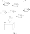
- FIG. 1 is a block diagram illustrating an RFID system according to some embodiments.
- an RFID system 8 includes: an RF reader unit 12 (inductive coupling reader) and a plurality of RF identification tags 16, 18, 20, 22, 24, 26 that are each attached to a corresponding item-of-interest 34, 36, 38, 40, 42, and 44 for use in identifying the item-of-interest.
- the items-of-interest 34, 36, 38, 40, 42, and 44 can include, for example, pieces of inventory, personnel, capital assets, animals, or any other objects for which it may be desirable to track or monitor within a particular region.
- the number of items that a particular reader is capable of tracking is generally a matter of design choice.
- the RF reader unit 12 can be a stationary unit, such as wall mounted proximity readers, or a portable unit that can be easily relocated.
- the coverage region serviced by an RF reader unit will be a function of the transmit power level of the reader, the antenna pattern of the reader transmit antenna, and the location and orientation of the reader at any particular time.
- the RF reader unit 12 periodically interrogates its coverage region 52 to identify the items-of-interest that are presently located therein. That is, the reader unit 12 periodically transmits an RF interrogation signal within the coverage region 52 that acts as a "request" for each of the RF identification tags 16-26 within the region 52 to transmit its identification signal identifying the associated item-of-interest.
- the RF interrogation signal drives a resonance circuit at a particular frequency that matches the resonance frequency of the resonance circuit.
- the RF tag receives the RF interrogation signal and derives a local clock frequency based on the RF interrogation signal.
- the RF tag synchronizes the exchange of data with the reader unit 12 according to the local clock frequency and, in turn, the drive frequency of the RF interrogation signal.
- Each of the RF tags within the coverage region 52 receives the interrogation signal and responds by transmitting its identification signal back to the interrogating reader. After receiving identification information from all of the RF tags within its coverage region 52, the RF reader unit reports the collected information to an appropriate entity.
- the RF reader unit 12 may be wall mounted on a wall that includes metal material.
- Such metal material can influence the resonance circuit of the RF reader unit 12 and change the resonance frequency of the resonance circuit. This can reduce the range of the RF reader unit 12, causing the RF reader unit 12 to misidentify or fail to identify items within the region 52 that are further away from the RF reader unit 12.
- the resonance frequency of the resonance circuit changes, the drive frequency of the interrogation signal may correspond to the expected resonance frequency under conditions in which interference is not present. Because the drive frequency and resonance frequency mismatch, the overall power consumed by the system increases and range of the RF reader unit 12 decreases. Namely, the size of the region 52 may be reduced when metal material is present in proximity to the RF reader unit 12. Also, the amount of power needed by the RF reader unit 12 to properly operate may be increased because the resonance frequency of the RF reader unit 12 changes.
- a method and apparatus are provided for reducing the negative effects of interference within an RFID system by modifying the excitation (drive) frequency that is applied to the resonance circuit to compensate for metal material determined to cause changes to the resonance frequency of the RF reader unit 12.
- FIG. 2A is a block diagram illustrating an RF reader unit 200 in accordance with one embodiment of the present disclosure.
- RF reader unit 200 may be illustrative of RF reader unit 12 ( FIG. 1 ).
- the reader unit 200 can include: a tuned circuit 210, a driver circuit 230, a receiver circuit 240, an antenna voltage detection circuit 250, and a microcontroller 220.
- the antenna voltage detection circuit 250 can be excluded or deactivated from the RF reader unit 200.
- the microcontroller 220 is operative for controlling the operation of the RF reader unit 200 in order to interrogate, track, and report on items-of-interest within the coverage region 52 of the RF reader unit 200.
- the microcontroller 220 is implemented using a digital processing device, such as a general purpose microprocessor, a digital signal processor, a reduced instruction set computer, a complex instruction set computer, or a field programmable gate array.
- a digital processing device such as a general purpose microprocessor, a digital signal processor, a reduced instruction set computer, a complex instruction set computer, or a field programmable gate array.
- one or more of the other functional blocks illustrated in FIG. 2A can also be implemented digitally within the same (or a different) digital processor as the microcontroller 220.
- the microcontroller 220 can include an adjustable frequency timer and volatile and non-volatile memory.
- the tuned circuit 210 includes an inductive loop antenna and tuning capacitance.
- the tuned circuit 210 is used to generate and transmit interrogation signals (under the control of the microcontroller 220 and driver circuit 230) for transmission into the coverage region 52 via the inductive loop antenna during an interrogation operation.
- the receiver circuit 240 is operative for, among other things, receiving, demodulating, and decoding identification signals received from RF tags located within the coverage region 52 and for delivering the resulting identification information to the microcontroller 220.
- the microcontroller 220 detects a change in a resonance frequency of the RF reader unit 200. Specifically, the microcontroller 220 detects a change in the resonance frequency of the tuned circuit 210. In some implementations, the microcontroller 220 detects the change in the resonance frequency based on a pre-configured setting of the microcontroller 220 that is stored in the non-volatile memory of the microcontroller 220. For example, during operation or during manufacture of the RF reader unit 200, a configuration bit stored in the non-volatile memory of the microcontroller 220 may indicate presence or lack of presence of an interference source, such as a metal material.
- an interference source such as a metal material.
- the microcontroller 220 may access that configuration bit, during operation, and determine whether the configuration bit is asserted or de-asserted. If the configuration bit is asserted, the microcontroller 220 determines that an interference source, such as a metal material, is present or within a close proximity to the RF reader unit 200. In such cases, the microcontroller 220 detects a change in the resonance frequency of the RF reader unit 200. If the configuration bit is de-asserted, the microcontroller 220 determines that there is no presence of an interference source.
- an interference source such as a metal material
- the microcontroller 220 communicates with the antenna voltage detection circuit 250 to determine and detect a change in the resonance frequency of the RF reader unit 200. Specifically, the microcontroller 220 may measure an amount of voltage consumed by the tuned circuit 210 using the antenna voltage detection circuit 250 when an interrogation signal with a given excitation frequency is applied to the tuned circuit 210. The given excitation frequency that is applied matches the expected resonance frequency of the tuned circuit 210 (e.g., the resonance frequency the tuned circuit 210 normally operates at when no interference sources are present). For example, the tuned circuit 210 may be configured to operated at a resonance frequency of 125kHz or 134kHz or any other suitable value.
- the excitation frequency of the interrogation signal is also set to 125kHz or 134kHz to match the resonance frequency. If the amount of voltage fails to satisfy a threshold or falls below a specified threshold value (e.g., because the resonance frequency does not match the excitation frequency), the microcontroller 220 detects the change in the resonance frequency.
- the microcontroller 220 adjusts the excitation frequency of the interrogation signal using the adjustable frequency timer to offset the change in the resonance frequency. For example, if the resonance frequency is 10% higher than the expected resonance frequency, the microcontroller 220 increases the excitation frequency by 10%.
- the preset threshold against which the voltage measured by the antenna voltage detection circuit 250 is compared against may be set to a value that is 10% (or any other suitable percentage or value) higher or 10% (or any other suitable percentage or value) lower than the value of the voltage consumed by the tuned circuit 210 when no metal material is in close proximity to the RF reader unit 200.
- the preset threshold may be programmed into a look-up table or memory during manufacture of the RF reader unit 200 and/or may be dynamically updated based on different operating conditions. In some cases, the preset threshold may be a particular value or may be a range of values. If the measured voltage falls outside of the range of values, the microcontroller 220 detects a change in the resonance frequency and adjusts the excitation frequency of the interrogation circuit by a specified amount.
- the microcontroller 220 instructs the driver circuit 230 to operate at a first frequency or a second frequency.
- the first frequency may correspond to the resonance frequency of the tuned circuit 210 under normal conditions when no interference sources are present.
- the microcontroller 220 instructs the driver circuit 230 to operate at a second frequency which is higher or lower than the first frequency.
- the microcontroller 220 searches for the optimal excitation frequency of the interrogation signal based on voltage values measured by the antenna voltage detection circuit 250. For example, the microcontroller 220 may initially drive the tuned circuit 210 at a first frequency corresponding to the resonance frequency of the tuned circuit 210 under normal conditions when no interference sources are present. The microcontroller 220 receives a first voltage measurement from the antenna voltage detection circuit 250. The microcontroller 220 stores this first voltage measurement in the volatile memory of the microcontroller 220. Next, the microcontroller 220 increases the excitation frequency to drive the tuned circuit 210 at a second frequency that is higher than the first frequency. The microcontroller 220 receives a second voltage measurement from the antenna voltage detection circuit 250.
- the microcontroller 220 compares the second voltage measurement to the first voltage measurement. In response to determining that the second voltage measurement is greater than the first voltage measurement, the microcontroller 220 may increase the excitation frequency to drive the tuned circuit 210 at a third frequency that is higher than the second frequency. Alternatively, in response to determining that the second voltage measurement is greater than the first voltage measurement, the microcontroller 220 may set the excitation frequency to drive the tuned circuit 210 at the second frequency. In response to determining that the second voltage measurement is less than the first voltage measurement, the microcontroller 220 may decrease the excitation frequency to drive the tuned circuit 210 at a third frequency that is lower than the first frequency. Alternatively, in response to determining that the second voltage measurement is less than the first voltage measurement, the microcontroller 220 may set the excitation frequency to drive the tuned circuit 210 at the first frequency.
- the microcontroller 220 again compares the resulting voltage measured by the antenna voltage detection circuit 250 due to driving the tuned circuit 210 at the third frequency with the voltage resulting from driving the tuned circuit 210 at the prior frequency.
- the microcontroller 220 may continue gradually increasing the drive frequency by specified amounts until the resulting voltage is less than the previously measured voltage.
- the microcontroller 220 may continue gradually decreasing the drive frequency by specified amounts until the resulting voltage is less than the previously measured voltage.
- the microcontroller 220 sets the drive frequency to the frequency that resulted in the previously measured voltage. Namely, the microcontroller 220 searches for the frequency (by gradually increasing or decreasing the drive frequency) that results in the maximum voltage measurement output by the antenna voltage detection circuit 250.
- FIG. 2B is an illustrative RFID system driving frequency versus resonance frequency waveform in accordance with various embodiments.
- the antenna voltage (and thereby the range of the RFID system) is reduced as the drive frequency of the interrogation signal applied to the resonance circuit mismatches the resonance frequency of the resonance circuit.
- the antenna voltage is at a maximum value when the drive frequency matches the resonance or resonant frequency of the resonance circuit.
- the resonance frequency of the resonance circuit is a preset value of 125kHz or 134kHz.
- the excitation frequency of the interrogation signal applied to the resonance circuit is also 125kHz or 134kHz and is set to equal or match the value of the resonance frequency.
- the resulting voltage measured by the antenna voltage detection circuit 250 is close to or at a maximum value.
- the RF reader unit 200 is placed in close proximity to an interference source, such a metal material, which changes the resonance frequency of the resonance circuit (e.g., from 125kHz to 135kHz).
- Driving the resonance circuit at the currently set excitation frequency e.g., at 125kHz
- the excitation frequency is increased or decreased by a specified amount which may match the changed resonance frequency of the resonance circuit.
- Driving the resonance circuit at the adjusted excitation frequency results in a voltage measurement provided by the antenna voltage detection circuit 250 that is close to or that equals the maximum value.
- an inductive coupling device receives the RF interrogation signal at the adjusted excitation frequency and derives a local clock frequency based on the RF interrogation signal (e.g., at 135kHz).
- the inductive coupling device synchronizes the exchange of data with the reader unit 12 according to the local clock frequency and, in turn, the adjusted excitation (drive) frequency of the RF interrogation signal.
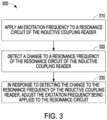
- FIG. 3 is a flow diagram depicting an example process 300 for operating an inductive coupling reader in accordance with various embodiments.
- the inductive coupling reader applies an excitation frequency to a resonance circuit of the inductive coupling reader.
- the inductive coupling reader detects a change to the resonance frequency of the resonance circuit of the inductive coupling reader.
- the inductive coupling reader adjusts the excitation frequency being applied to the resonance circuit in response to detecting the change to the resonance frequency of the inductive coupling reader.
- FIG. 4 is a block diagram of an example machine 400 upon which any one or more of the techniques (e.g., methodologies) discussed herein may be performed and/or that may be included as part of an inductive coupling reader.
- the machine 400 may operate as a standalone device or may be connected (e.g., networked) to other machines.
- the machine 400 may operate in the capacity of a server machine, a client machine, or both in server-client network environments.
- the machine 400 may act as a peer machine in a peer-to-peer (P2P) (or other distributed) network environment.
- P2P peer-to-peer
- the machine 400 may be a personal computer (PC), a tablet PC, a set-top box (STB), a personal digital assistant (PDA), a mobile telephone, a web appliance, an IoT device, an automotive system, an aerospace system, or any machine capable of executing instructions (sequential or otherwise) that specify actions to be taken by that machine.
- PC personal computer
- PDA personal digital assistant
- STB set-top box
- IoT device an automotive system
- aerospace system or any machine capable of executing instructions (sequential or otherwise) that specify actions to be taken by that machine.
- machine shall also be taken to include any collection of machines that individually or jointly execute a set (or multiple sets) of instructions to perform any one or more of the methodologies discussed herein, such as via cloud computing, software as a service (SaaS), or other computer cluster configurations.
- Circuitry is a collection (e.g., set) of circuits implemented in tangible entities that include hardware (e.g., simple circuits, gates, logic, etc.). Circuitry membership may be flexible over time and underlying hardware variability. Circuitries include members that may, alone or in combination, perform specific tasks when operating. In an example, hardware of the circuitry may be immutably designed to carry out a specific operation (e.g., hardwired).
- the hardware of the circuitry may include variably connected physical components (e.g., execution units, transistors, simple circuits, etc.) including a computer-readable medium physically modified (e.g., magnetically, electrically, by moveable placement of invariant-massed particles, etc.) to encode instructions of the specific operation.
- a computer-readable medium physically modified (e.g., magnetically, electrically, by moveable placement of invariant-massed particles, etc.) to encode instructions of the specific operation.
- the instructions enable participating hardware (e.g., the execution units or a loading mechanism) to create members of the circuitry in hardware via the variable connections to carry out portions of the specific tasks when in operation.
- the computer-readable medium is communicatively coupled to the other components of the circuitry when the device is operating.
- any of the physical components may be used in more than one member of more than one circuitry.
- execution units may be used in a first circuit of a first circuitry at one point in time and reused by a second circuit in the first circuitry, or by a third circuit in a second circuitry, at a different time.
- the machine 400 may include a hardware processor 402 (e.g., a central processing unit (CPU), a graphics processing unit (GPU), a hardware processor core, or any combination thereof, such as a memory controller, etc.), a main memory 404, and a static memory 406, some or all of which may communicate with each other via an interlink (e.g., bus) 408.
- the machine 400 may further include a display device 410, an alphanumeric input device 412 (e.g., a keyboard), and a user interface (UI) navigation device 414 (e.g., a mouse).
- the display device 410, alphanumeric input device 412, and UI navigation device 414 may be a touchscreen display.
- the machine 400 may additionally include a storage device 422 (e.g., drive unit); a signal generation device 418 (e.g., a speaker); a network interface device 420; one or more sensors 416, such as a Global Positioning System (GPS) sensor, wing sensors, mechanical device sensors, temperature sensors, ICP sensors, bridge sensors, audio sensors, industrial sensors, a compass, an accelerometer, or other sensors.
- a storage device 422 e.g., drive unit
- a signal generation device 418 e.g., a speaker
- a network interface device 420 e.g., a network interface device 420
- sensors 416 such as a Global Positioning System (GPS) sensor, wing sensors, mechanical device sensors, temperature sensors, ICP sensors, bridge sensors, audio sensors, industrial sensors, a compass, an accelerometer, or other sensors.
- GPS Global Positioning System
- the machine 400 may include an output controller 428, such as a serial (e.g., universal serial bus (USB)), parallel, or other wired or wireless (e.g., infrared (IR), near field communication (NFC), etc.) connection to communicate with or control one or more peripheral devices (e.g., a printer, card reader, etc.).
- a serial e.g., universal serial bus (USB)
- parallel e.g., parallel
- wired or wireless e.g., infrared (IR), near field communication (NFC), etc.
- peripheral devices e.g., a printer, card reader, etc.
- the storage device 422 may include a machine-readable medium on which is stored one or more sets of data structures or instructions 424 (e.g., software) embodying or utilized by any one or more of the techniques or functions described herein.
- the instructions 424 may also reside, completely or at least partially, within the main memory 404, within the static memory 406, or within the hardware processor 402 during execution thereof by the machine 400.
- one or any combination of the hardware processor 402, the main memory 404, the static memory 406, or the storage device 421 may constitute the machine-readable medium.
- machine-readable medium is illustrated as a single medium, the term “machine-readable medium” may include a single medium or multiple media (e.g., a centralized or distributed database, or associated caches and servers) configured to store the one or more instructions 424.
- machine-readable medium may include a single medium or multiple media (e.g., a centralized or distributed database, or associated caches and servers) configured to store the one or more instructions 424.
- machine-readable medium may include any transitory or non-transitory medium that is capable of storing, encoding, or carrying transitory or non-transitory instructions for execution by the machine 400 and that cause the machine 400 to perform any one or more of the techniques of the present disclosure, or that is capable of storing, encoding, or carrying data structures used by or associated with such instructions.
- Non-limiting machine-readable medium examples may include solid-state memories, and optical and magnetic media.
- a massed machine-readable medium comprises a machine-readable medium with a plurality of particles having invariant (e.g., rest) mass. Accordingly, massed machine-readable media are not transitory propagating signals.
- massed machine-readable media may include non-volatile memory, such as semiconductor memory devices (e.g., Electrically Programmable Read-Only Memory (EPROM), Electrically Erasable Programmable Read-Only Memory (EEPROM)) and flash memory devices; magnetic disks, such as internal hard disks and removable disks; magnetooptical disks; and CD-ROM and DVD-ROM disks.
- semiconductor memory devices e.g., Electrically Programmable Read-Only Memory (EPROM), Electrically Erasable Programmable Read-Only Memory (EEPROM)
- flash memory devices e.g., Electrically Programmable Read-Only Memory (EPROM), Electrically Erasable Programmable Read-Only Memory (EEPROM)
- EPROM Electrically Programmable Read-Only Memory
- EEPROM Electrically Erasable Programmable Read-Only Memory
- the instructions 424 (e.g., software, programs, an operating system (OS), etc.) or other data that are stored on the storage device 421 can be accessed by the main memory 404 for use by the hardware processor 402.
- the main memory 404 e.g., DRAM
- the main memory 404 is typically fast, but volatile, and thus a different type of storage from the storage device 421 (e.g., an SSD), which is suitable for long-term storage, including while in an "off" condition.
- the instructions 424 or data in use by a user or the machine 400 are typically loaded in the main memory 404 for use by the hardware processor 402.
- virtual space from the storage device 421 can be allocated to supplement the main memory 404; however, because the storage device 421 is typically slower than the main memory 404, and write speeds are typically at least twice as slow as read speeds, use of virtual memory can greatly reduce user experience due to storage device latency (in contrast to the main memory 404, e.g., DRAM). Further, use of the storage device 421 for virtual memory can greatly reduce the usable lifespan of the storage device 421.
- the instructions 424 may further be transmitted or received over a communications network 426 using a transmission medium via the network interface device 420 utilizing any one of a number of transfer protocols (e.g., frame relay, internet protocol (IP), transmission control protocol (TCP), user datagram protocol (UDP), hypertext transfer protocol (HTTP), etc.).
- transfer protocols e.g., frame relay, internet protocol (IP), transmission control protocol (TCP), user datagram protocol (UDP), hypertext transfer protocol (HTTP), etc.
- Example communication networks may include a local area network (LAN), a wide area network (WAN), a packet data network (e.g., the Internet), mobile telephone networks (e.g., cellular networks), Plain Old Telephone Service (POTS) networks, and wireless data networks (e.g., Institute of Electrical and Electronics Engineers (IEEE) 802.11 family of standards known as Wi-Fi ® , IEEE 802.16 family of standards known as WiMax ® , IEEE 802.15.4 family of standards, peer-to-peer (P2P) networks), among others.
- the network interface device 420 may include one or more physical jacks (e.g., Ethernet, coaxial, or phone jacks) or one or more antennas to connect to the communications network 426.
- the network interface device 420 may include a plurality of antennas to wirelessly communicate using at least one of single-input multiple-output (SIMO), multiple-input multiple-output (MIMO), or multiple-input single-output (MISO) techniques.
- SIMO single-input multiple-output
- MIMO multiple-input multiple-output
- MISO multiple-input single-output
- transmission medium shall be taken to include any tangible or intangible medium that is capable of storing, encoding, or carrying instructions for execution by the machine 400, and includes digital or analog communications signals or other tangible or intangible media to facilitate communication of such software.
- Method examples described herein may be machine- or computer-implemented at least in part. Some examples may include a computer-readable medium or machine-readable medium encoded with transitory or non-transitory instructions operable to configure an electronic device to perform methods as described in the above examples.
- An implementation of such methods may include code, such as microcode, assembly-language code, a higher-level-language code, or the like. Such code may include transitory or non-transitory computer-readable instructions for performing various methods.
- the code may form portions of computer program products. Further, in an example, the code may be tangibly stored on one or more volatile, non-transitory, or non-volatile tangible computer-readable media, such as during execution or at other times.
- Examples of these tangible computer-readable media may include, but are not limited to, hard disks, removable magnetic disks, removable optical disks (e.g., compact discs and digital video discs), magnetic cassettes, memory cards or sticks, random access memories (RAMs), read-only memories (ROMs), and the like.
Landscapes
- Engineering & Computer Science (AREA)
- Physics & Mathematics (AREA)
- Computer Networks & Wireless Communication (AREA)
- Health & Medical Sciences (AREA)
- Toxicology (AREA)
- Theoretical Computer Science (AREA)
- General Physics & Mathematics (AREA)
- Electromagnetism (AREA)
- Artificial Intelligence (AREA)
- Computer Vision & Pattern Recognition (AREA)
- Signal Processing (AREA)
- General Health & Medical Sciences (AREA)
- Computer Hardware Design (AREA)
- Microelectronics & Electronic Packaging (AREA)
- Near-Field Transmission Systems (AREA)
- Radar Systems Or Details Thereof (AREA)
Applications Claiming Priority (3)
| Application Number | Priority Date | Filing Date | Title |
|---|---|---|---|
| US16/705,574 US11206061B2 (en) | 2019-12-06 | 2019-12-06 | Dynamic frequency tuning for inductive coupling systems |
| EP20815770.1A EP4055513B1 (de) | 2019-12-06 | 2020-11-25 | Dynamische frequenzabstimmung für induktive kopplungssysteme |
| PCT/EP2020/083415 WO2021110517A1 (en) | 2019-12-06 | 2020-11-25 | Dynamic frequency tuning for inductive coupling systems |
Related Parent Applications (1)
| Application Number | Title | Priority Date | Filing Date |
|---|---|---|---|
| EP20815770.1A Division EP4055513B1 (de) | 2019-12-06 | 2020-11-25 | Dynamische frequenzabstimmung für induktive kopplungssysteme |
Publications (2)
| Publication Number | Publication Date |
|---|---|
| EP4404099A2 true EP4404099A2 (de) | 2024-07-24 |
| EP4404099A3 EP4404099A3 (de) | 2024-10-30 |
Family
ID=73598860
Family Applications (2)
| Application Number | Title | Priority Date | Filing Date |
|---|---|---|---|
| EP24168058.6A Pending EP4404099A3 (de) | 2019-12-06 | 2020-11-25 | Dynamische frequenzabstimmung für induktive kopplungssysteme |
| EP20815770.1A Active EP4055513B1 (de) | 2019-12-06 | 2020-11-25 | Dynamische frequenzabstimmung für induktive kopplungssysteme |
Family Applications After (1)
| Application Number | Title | Priority Date | Filing Date |
|---|---|---|---|
| EP20815770.1A Active EP4055513B1 (de) | 2019-12-06 | 2020-11-25 | Dynamische frequenzabstimmung für induktive kopplungssysteme |
Country Status (8)
| Country | Link |
|---|---|
| US (1) | US11206061B2 (de) |
| EP (2) | EP4404099A3 (de) |
| JP (3) | JP7432724B2 (de) |
| KR (3) | KR102891277B1 (de) |
| CN (2) | CN114830124B (de) |
| CA (1) | CA3160586A1 (de) |
| MX (2) | MX2022006794A (de) |
| WO (1) | WO2021110517A1 (de) |
Families Citing this family (2)
| Publication number | Priority date | Publication date | Assignee | Title |
|---|---|---|---|---|
| US11206061B2 (en) | 2019-12-06 | 2021-12-21 | Assa Abloy Ab | Dynamic frequency tuning for inductive coupling systems |
| CN119582884A (zh) * | 2024-08-13 | 2025-03-07 | 支付宝(杭州)信息技术有限公司 | 近场通信方法及设备 |
Family Cites Families (21)
| Publication number | Priority date | Publication date | Assignee | Title |
|---|---|---|---|---|
| DE4327642C2 (de) * | 1993-05-17 | 1998-09-24 | Anatoli Stobbe | Lesegerät für ein Detektierplättchen |
| TW376598B (en) * | 1997-02-05 | 1999-12-11 | Em Microelectronic Marin Sa | Base station for a contactless interrogation system comprising a phase locked and voltage controlled oscillator |
| US6476708B1 (en) * | 1998-03-20 | 2002-11-05 | Hid Corporation | Detection of an RFID device by an RF reader unit operating in a reduced power state |
| US6317027B1 (en) * | 1999-01-12 | 2001-11-13 | Randy Watkins | Auto-tunning scanning proximity reader |
| US6650227B1 (en) * | 1999-12-08 | 2003-11-18 | Hid Corporation | Reader for a radio frequency identification system having automatic tuning capability |
| JP2003323595A (ja) | 2002-05-01 | 2003-11-14 | Matsushita Electric Ind Co Ltd | 非接触icカードリーダライタ装置 |
| US8830035B2 (en) * | 2005-06-30 | 2014-09-09 | Farpointe Data, Inc. | Power consumption management for an RFID reader |
| GB2433381B (en) * | 2005-12-16 | 2008-03-05 | Nicholas Patrick Roland Hill | Resonant circuits |
| JP2008160312A (ja) * | 2006-12-21 | 2008-07-10 | Toshiba Corp | 無線通信装置 |
| WO2009052473A1 (en) * | 2007-10-19 | 2009-04-23 | Destron Fearing Corporation | Automatic tuning reader |
| JP5146664B2 (ja) * | 2008-05-27 | 2013-02-20 | ブラザー工業株式会社 | 無線タグ通信装置 |
| GB2465223A (en) * | 2008-11-14 | 2010-05-19 | Cambridge Resonant Technologies Ltd | Tuned resonant circuits |
| FR2953314B1 (fr) * | 2009-12-01 | 2012-10-26 | Schneider Electric Ind Sas | Prolongateur d'antenne rfid auto-parametrable |
| DE102012015406A1 (de) | 2012-08-01 | 2014-02-06 | Gantner Electronic Gmbh | Verfahren und Vorrichtung zur Optimierung des RFID-Feldes einer Zugangskontrolleinrichtung |
| JP5839629B1 (ja) | 2014-07-18 | 2016-01-06 | デクセリアルズ株式会社 | 非接触通信装置、アンテナ回路、アンテナ駆動装置、非接触給電装置、チューニング方法、ディスカバリ方法、およびこれらの方法を実現するプログラム |
| GB2524602B (en) * | 2014-10-24 | 2016-02-10 | William Redman-White | Electronic Tuning System |
| US10102697B2 (en) * | 2015-10-31 | 2018-10-16 | Disney Enterprises, Inc. | High-Q and over-coupled near-field RFID reader antenna for improved tag read range |
| US10097095B2 (en) * | 2016-09-21 | 2018-10-09 | General Electric Company | DC converters with modified droop control and method of use |
| US10455392B2 (en) * | 2017-09-27 | 2019-10-22 | Apple Inc. | Adaptive matching with antenna detuning detection |
| US10956692B2 (en) * | 2018-11-27 | 2021-03-23 | Geissler Companies, Llc | Tag reader receiver with high-Q antenna |
| US11206061B2 (en) | 2019-12-06 | 2021-12-21 | Assa Abloy Ab | Dynamic frequency tuning for inductive coupling systems |
-
2019
- 2019-12-06 US US16/705,574 patent/US11206061B2/en active Active
-
2020
- 2020-11-25 WO PCT/EP2020/083415 patent/WO2021110517A1/en not_active Ceased
- 2020-11-25 KR KR1020247016601A patent/KR102891277B1/ko active Active
- 2020-11-25 MX MX2022006794A patent/MX2022006794A/es unknown
- 2020-11-25 EP EP24168058.6A patent/EP4404099A3/de active Pending
- 2020-11-25 KR KR1020257039110A patent/KR20250171435A/ko active Pending
- 2020-11-25 JP JP2022533501A patent/JP7432724B2/ja active Active
- 2020-11-25 KR KR1020227023171A patent/KR102668533B1/ko active Active
- 2020-11-25 CN CN202080084488.4A patent/CN114830124B/zh active Active
- 2020-11-25 CA CA3160586A patent/CA3160586A1/en active Pending
- 2020-11-25 EP EP20815770.1A patent/EP4055513B1/de active Active
- 2020-11-25 CN CN202511355037.0A patent/CN121279330A/zh active Pending
-
2022
- 2022-06-03 MX MX2025013534A patent/MX2025013534A/es unknown
-
2024
- 2024-02-05 JP JP2024015807A patent/JP7648816B2/ja active Active
-
2025
- 2025-03-06 JP JP2025035614A patent/JP2025090669A/ja active Pending
Also Published As
| Publication number | Publication date |
|---|---|
| JP2025090669A (ja) | 2025-06-17 |
| US20210175934A1 (en) | 2021-06-10 |
| EP4404099A3 (de) | 2024-10-30 |
| CN114830124B (zh) | 2025-10-17 |
| KR20250171435A (ko) | 2025-12-08 |
| US11206061B2 (en) | 2021-12-21 |
| JP7432724B2 (ja) | 2024-02-16 |
| JP2023505249A (ja) | 2023-02-08 |
| EP4055513B1 (de) | 2024-04-03 |
| KR102668533B1 (ko) | 2024-05-30 |
| EP4055513C0 (de) | 2024-04-03 |
| KR20240074021A (ko) | 2024-05-27 |
| KR20220106214A (ko) | 2022-07-28 |
| MX2022006794A (es) | 2022-09-09 |
| CN114830124A (zh) | 2022-07-29 |
| JP7648816B2 (ja) | 2025-03-18 |
| MX2025013534A (es) | 2025-12-01 |
| JP2024036509A (ja) | 2024-03-15 |
| WO2021110517A1 (en) | 2021-06-10 |
| CA3160586A1 (en) | 2021-06-10 |
| CN121279330A (zh) | 2026-01-06 |
| KR102891277B1 (ko) | 2025-11-26 |
| EP4055513A1 (de) | 2022-09-14 |
Similar Documents
| Publication | Publication Date | Title |
|---|---|---|
| JP2025090669A (ja) | 誘導結合システムにおける動的周波数同調 | |
| US7649441B2 (en) | Method and system for tuning an RFID interrogator | |
| CN101814154A (zh) | 信息处理设备、通信控制方法和程序 | |
| EP3681103A1 (de) | Steuerungssystem für eine hochfrequenzkommunikationsvorrichtung | |
| US9767328B2 (en) | Autonomous tuning method to improve radio frequency performance | |
| JP2025094023A (ja) | 誘導結合システムの離調検出および補償 | |
| Dos Santos et al. | Optimized ultra-low power sensor-enabled RFID data logger for pharmaceutical cold chain | |
| US20080106380A1 (en) | Method and system for tuning an rfid interrogator | |
| Igarashi et al. | A network architecture for fast retrieval of user memory data from sensor RF tags | |
| KR20150043846A (ko) | 근거리 무선 통신 모듈 및 방법 |
Legal Events
| Date | Code | Title | Description |
|---|---|---|---|
| PUAI | Public reference made under article 153(3) epc to a published international application that has entered the european phase |
Free format text: ORIGINAL CODE: 0009012 |
|
| STAA | Information on the status of an ep patent application or granted ep patent |
Free format text: STATUS: THE APPLICATION HAS BEEN PUBLISHED |
|
| AC | Divisional application: reference to earlier application |
Ref document number: 4055513 Country of ref document: EP Kind code of ref document: P |
|
| AK | Designated contracting states |
Kind code of ref document: A2 Designated state(s): AL AT BE BG CH CY CZ DE DK EE ES FI FR GB GR HR HU IE IS IT LI LT LU LV MC MK MT NL NO PL PT RO RS SE SI SK SM TR |
|
| PUAL | Search report despatched |
Free format text: ORIGINAL CODE: 0009013 |
|
| AK | Designated contracting states |
Kind code of ref document: A3 Designated state(s): AL AT BE BG CH CY CZ DE DK EE ES FI FR GB GR HR HU IE IS IT LI LT LU LV MC MK MT NL NO PL PT RO RS SE SI SK SM TR |
|
| RIC1 | Information provided on ipc code assigned before grant |
Ipc: H04B 5/26 20240101ALI20240923BHEP Ipc: G06K 7/10 20060101AFI20240923BHEP |
|
| STAA | Information on the status of an ep patent application or granted ep patent |
Free format text: STATUS: REQUEST FOR EXAMINATION WAS MADE |
|
| 17P | Request for examination filed |
Effective date: 20250424 |
|
| GRAP | Despatch of communication of intention to grant a patent |
Free format text: ORIGINAL CODE: EPIDOSNIGR1 |
|
| STAA | Information on the status of an ep patent application or granted ep patent |
Free format text: STATUS: GRANT OF PATENT IS INTENDED |
|
| INTG | Intention to grant announced |
Effective date: 20251127 |