EP4403984A1 - Brillenglas - Google Patents
Brillenglas Download PDFInfo
- Publication number
- EP4403984A1 EP4403984A1 EP22869721.5A EP22869721A EP4403984A1 EP 4403984 A1 EP4403984 A1 EP 4403984A1 EP 22869721 A EP22869721 A EP 22869721A EP 4403984 A1 EP4403984 A1 EP 4403984A1
- Authority
- EP
- European Patent Office
- Prior art keywords
- area
- spectacle lens
- convergence
- functional
- functional area
- Prior art date
- Legal status (The legal status is an assumption and is not a legal conclusion. Google has not performed a legal analysis and makes no representation as to the accuracy of the status listed.)
- Pending
Links
Images


Classifications
-
- G—PHYSICS
- G02—OPTICS
- G02C—SPECTACLES; SUNGLASSES OR GOGGLES INSOFAR AS THEY HAVE THE SAME FEATURES AS SPECTACLES; CONTACT LENSES
- G02C7/00—Optical parts
-
- G—PHYSICS
- G02—OPTICS
- G02C—SPECTACLES; SUNGLASSES OR GOGGLES INSOFAR AS THEY HAVE THE SAME FEATURES AS SPECTACLES; CONTACT LENSES
- G02C7/00—Optical parts
- G02C7/02—Lenses; Lens systems ; Methods of designing lenses
- G02C7/06—Lenses; Lens systems ; Methods of designing lenses bifocal; multifocal ; progressive
-
- G—PHYSICS
- G02—OPTICS
- G02C—SPECTACLES; SUNGLASSES OR GOGGLES INSOFAR AS THEY HAVE THE SAME FEATURES AS SPECTACLES; CONTACT LENSES
- G02C7/00—Optical parts
- G02C7/02—Lenses; Lens systems ; Methods of designing lenses
-
- G—PHYSICS
- G02—OPTICS
- G02C—SPECTACLES; SUNGLASSES OR GOGGLES INSOFAR AS THEY HAVE THE SAME FEATURES AS SPECTACLES; CONTACT LENSES
- G02C7/00—Optical parts
- G02C7/02—Lenses; Lens systems ; Methods of designing lenses
- G02C7/022—Ophthalmic lenses having special refractive features achieved by special materials or material structures
-
- G—PHYSICS
- G02—OPTICS
- G02C—SPECTACLES; SUNGLASSES OR GOGGLES INSOFAR AS THEY HAVE THE SAME FEATURES AS SPECTACLES; CONTACT LENSES
- G02C7/00—Optical parts
- G02C7/16—Shades; shields; Obturators, e.g. with pinhole, with slot
-
- G—PHYSICS
- G02—OPTICS
- G02C—SPECTACLES; SUNGLASSES OR GOGGLES INSOFAR AS THEY HAVE THE SAME FEATURES AS SPECTACLES; CONTACT LENSES
- G02C2202/00—Generic optical aspects applicable to one or more of the subgroups of G02C7/00
- G02C2202/24—Myopia progression prevention
Definitions
- the present invention relates to a spectacle lens.
- a spectacle lens that suppresses a progression of refractive error such a myopia
- a lens that has multiple island-like areas formed thereon, having a refractive power more positive than a prescribed refractive power (for example, see Patent document 1).
- the spectacle lens with this configuration out of the light beams that enter from an object-side surface and exit from an eyeball-side surface, those that pass through areas other than defocus areas are focused on a wearer's retina, but the light beams that pass through the defocus areas are focused at a position in front of the retina. This will suppress the progression of myopia.
- FIG. 1 of Patent document 1 illustrates a case where the island-shaped areas are not provided at and near a geometric center of a lens.
- Patent documents 2 and 3 disclose spectacle lenses in which a predetermined configuration is provided at more outer edge side of the spectacle lens than at and near the geometric center of the spectacle lens in order to suppress the progression of myopic refractive error.
- the spectacle lenses described in Patent documents 2 and 3 do not have a configuration that exhibits an effect of suppressing the progression of myopia at and near the geometric center of the lens, in planar view ( FIG. 1 of Patent document 2, FIG. 5A of Patent document 3).
- Patent document 4 describes a spectacle lens including a base portion that allows light beams entering from an object-side surface to exit from an eyeball-side surface and converge at a position A on an eyeball's retina, and a defocus area that gives a positive or negative defocus to a transmitted light beam and has an effect of converging the light at a position different from the light transmitted through the base portion.
- Paragraph 0102 of the Patent document 4 describes that a function of suppressing the progression of hyperopia is achieved by changing a base material of a spectacle lens from a convex portion to a concave portion.
- the lens does not have the configuration that exhibits the effect of suppressing the progression of myopia or the effect of reducing hyperopia at and near the geometric center of the lens, in planar view.
- the area not having the configuration that suppresses the progression of myopia or reducing hyperopia is also referred to as a clear area.
- the clear area will be described later.
- an area having a configuration that exhibits an effect of suppressing the progression of myopia or an effect of reducing hyperopia (such as a configuration in which a concave area and/or a convex area is formed on the surface of a spectacle lens or a different refractive index is embedded inside the spectacle lens, for example, like the spectacle lens described in Patent documents 2 to 4.
- "retinal nonconvergence area” is also referred to as a functional area. The functional area will be discussed later.
- the functional area does not provide better visibility than the clear area.
- the functional area contributes to peripheral vision imaging.
- One aspect of the present invention is to provide a technique that makes it easier to obtain good visibility even in a peripheral vision when wearing spectacle lenses with a clear area and a functional area.
- a first aspect of the present invention provides a spectacle lens, including:
- a second aspect of the present invention provides a spectacle lens, including:
- a third aspect of the present invention provides the spectacle lens according to the first or second aspect, wherein in planar view, an area of the retinal non-convergence area provided within the functional area relative to an area of the retinal non-convergence area in the entire spectacle lens, is 80% or more (preferably 85% or more, 90% or more, 95% or more, 98% or more, 99% or more).
- a fourth aspect of the present invention provides the spectacle lens according to any one of the first to third aspects, wherein in planar view, an area of the retinal non-convergence area provided within the functional area is 20% or less (preferably 10% or less) of the area of the entire spectacle lens.
- a fifth aspect of the present invention provides the spectacle lens according to any one of the first to fourth aspects, wherein in the functional area, 30% or more of the light beam entering into the wearer's pupil is not allowed to converge on the retina.
- a sixth aspect of the present invention provides the spectacle lens according to any one of the first to fifth aspects, wherein in planar view, when the outer clear area is shaped as an aggregate of all circles with a radius r1 [mm] (r1 is any one value in a range of 1.50 or more and 2.50 or less), capable of circumscribing the retinal non-convergence area within the functional area without including other retinal non-convergence areas on the outer clear area side, the functional area falls within a circle centered on the eye point and having a diameter that is any one value of 15.00 to 25.00 mm (the one value is preferably 23.00mm, 22.00mm, 21.00mm, 20.00mm).
- a seventh aspect of the present invention provides the spectacle lens according to any one of the first to sixth aspects, wherein in planar view, when the central clear area is shaped as an aggregate of all circles with a radius r2 [mm] (r2 is any one value in a range of 1.50 or more and 2.50 or less) and capable of circumscribing the retinal non-convergence area within the functional area without including other retinal non-convergence areas on the central clear area side, the central clear area has a size that includes a circle centered on the eye point and having a diameter that is any one value of 4.00 to 13.00 mm, and has a size that falls within a circle with a diameter of other one value within the above range.
- r2 is any one value in a range of 1.50 or more and 2.50 or less
- An eighth aspect of the present invention provides the spectacle lens according to any one of the first to seventh aspects,
- the central clear area 2 has a size that includes a circle centered on the eye point EP and having a diameter that is any one of 4.00 mm or more and less than 13.00 mm (preferably 6.30 mm or more and less than 7.50 mm), and has a size that falls within a circle having a diameter that is other one value larger than the above one value and exceeding 4.00 mm and 13.00 mm or less (preferably exceeding 6.30 mm and 7.50 mm or less).
- the central clear area (and the base area within the functional area, and further the outer clear area) of one embodiment of the present invention functions as a so-called single focus lens.
- the aggregate may be read as an envelope surrounding the aggregate.
- the area (area ratio) of the retinal non-convergence area provided in the functional area relative to the area of the retinal non-convergence area in an entire spectacle lens is preferably 85% or more, 90% or more, 95% or more, 98% or more, and 99% or more in this order.
- the central clear area there is no limit in the size and shape of the central clear area, and the shape may be circular, rectangular, elliptical, etc.
- One guideline for a lower limit of the size of the central clear area is that it should be large enough to include a circle with a diameter of 4.00 mm centered on the eye point.
- One guideline for an upper limit of the size of the central clear area 2 is that it should fall within a circle with a diameter of 13.00 mm centered on the eye point.
- One guideline is that in the functional area, it may be defined that 30% or more (or 40% or more, 50% or more, 60% or more) of the light beam entering into a wearer's pupil is not allowed to converge on the retina.
- the upper limit may be, for example, 70%.
- the area of the retinal non-convergence area (convex area, embedding structure), which is a configuration that exhibits the effect of suppressing the progression of myopia or the effect of reducing hyperopia, may be defined as 20% or more and 80% or less of the entire functional area.
- the retinal non-convergence areas may be arranged sparsely toward the outer edge of the functional area.
- the area of the retinal non-convergence areas provided within the functional area relative to the area of the entire spectacle lens is 20% or less (or 15% or less, 10% or less).
- a lower limit is 5% or more.
- the configuration intended to provide an effect of suppressing the progression of myopia or an effect of reducing hyperopia is not provided between the outer edge of the spectacle lens and the functional area.
- an entire area between the outer edge of the spectacle lens and the functional area is the outer clear area.
- the technical idea of the present invention is also reflected in a pair of spectacle lenses in which one embodiment of the present invention is applied to each of a right-eye lens and a left-eye lens.
- the technical idea of the present invention is also reflected in a spectacle lens fitted into a frame, with a portion near its peripheral edge cut to match a specified frame shape.
- a technique that facilitates obtaining good visibility even in a peripheral vision when wearing spectacle lenses having clear areas and functional areas.
- the spectacle lens described in this specification has an object-side surface and an eyeball-side surface.
- the "object-side surface” is the surface located on an object side when spectacles equipped with spectacle lenses are worn by a wearer
- the "eyeball side surface” is the opposite thereof, that is, the surface located on an eyeball side when spectacles with spectacle lenses are worn by a wearer.
- This relationship also applies to a lens base material that is the basis of a spectacle lens.
- the lens base material also has the object-side surface and the eyeball-side surface.
- a horizontal direction is X direction
- a vertical (up and down) direction is Y direction
- a thickness direction of the spectacle lens and perpendicular to the X and Y directions is Z direction.
- Z direction is also an optical axis direction of the spectacle lens.
- the origin is at the center of the lens.
- the center of the lens refers to an optical center or a geometric center of the spectacle lens. This specification shows a case where the optical center and the geometric center substantially coincide with each other.
- planar view refers to a state when viewed from the +Z direction to the -Z direction.
- FIG. 1 Each figure of the present application illustrates a case where a right eye lens is viewed from above, and when the right eye lens is worn, a nasal side direction is the +X direction, and an ear side direction is the -X direction.
- a viewing state from the -Z direction to the +Z direction may be regarded as the planar view.
- positions such as an eye point and a geometric center of a spectacle lens, unless otherwise specified, it refers to the position in planar view.
- ...to refers to a value greater than or equal to a predetermined value and less than or equal to a predetermined value.
- a spectacle lens according to one aspect of the present invention includes a central clear area and a functional area.
- the central clear area is a portion having a smooth surface shape that can realize a prescribed refractive power of the wearer from a geometrical optics perspective, and for example, it is a transparent portion in a visible light wavelength range.
- the central clear area is a portion corresponding to a first refraction area of Patent document 1, and this is the area provided as a base area at and near a lens center of the spectacle lens illustrated in FIG. 5 of Patent document 4. Further, the central clear area is the area including a center of the lens and/or an eye point, and this is an area where the light beam entering from the object-side surface is allowed to exit from the eyeball-side surface, enter into the wearer's pupil, and converge on the retina.
- the prescribed refractive power can be achieved by the central clear area of one embodiment of the present invention.
- This spherical power may be a power that should be corrected when viewed with a front vision (a distance to an object is about infinity to 1m) (for example, it is a distance vision power, and hereafter, distance vision power will be exemplified.), or may be a power that should be corrected when viewed with an intermediate vision (1m to 40cm) or a near vision (40cm to 10cm).
- the central clear area does not have any configuration (eg, defocus area, convex area and/or concave area, embedding structure, etc.) intended to exhibit the effect of suppressing the progression of myopia or the effect of reducing hyperopia.
- any configuration eg, defocus area, convex area and/or concave area, embedding structure, etc.
- the central clear area (and the base area within the functional area, and further the outer clear area) of one embodiment of the present invention functions as a so-called single focus lens.
- Prescription data of wearer's information is written on a lens bag of the spectacle lens.
- the lens can be identified as a spectacle lens based on the prescription data of the wearer's information, and usually, the spectacle lens comes in a set with the lens bag. Therefore, the technical idea of the present invention is reflected in the spectacle lens with the lens bag attached thereto, and the same applies to the set of the lens bag and the spectacle lens.
- Eye point (EP) is, for example, the position where a line of sight passes when facing straight ahead when wearing the spectacle lenses, and an example of this will be given below.
- the eyepoint may be a position through which the wearer's line of sight passes when he or she visually recognizes an object close to the wearer (so to speak, during near vision), that is, a near vision eyepoint.
- One aspect of the present invention shows a case in which the geometric center of the spectacle lens before being fitted into a frame coincides with the eye point and also coincides with a prism reference point, and also coincides with the center of the lens.
- a spectacle lens before being fitted into a frame will be exemplified, but the present invention is not limited to this embodiment.
- the position of the eyepoint can be specified by referring to a remark chart or a centration chart issued by a lens manufacturer.
- the functional area is an area in which the light beam entering from the object-side surface is allowed to exit from the eyeball-side surface, while at least a part of the light beam entering into the wearer's pupil is not allowed to converge on the retina.
- the functional area is an annular area adjacent to and surrounding the central clear area in planar view.
- An entire annular functional area does not necessarily have a surface shape of the spectacle lens (such as an opaque one that has been treated like frosted glass) which is different from the shape of the central clear area, or does not necessarily have an internal embedding structure.
- a first refractive area a base area that performs the same function as the central clear area
- an annular area including the base area and the convex area may be regarded as a functional area.
- Patent document 2 shows a spectacle lens including a convex area formed in a ring shape in a beaded pattern in such a manner that a plurality of the convex areas are arranged in a radial direction, with an area where no convex area is formed being used as a base area.
- the area between the ring of the beaded pattern with a smallest diameter and the ring of the beaded pattern with a largest diameter may be set as a functional area.
- the functional area may be set as an area as an annular area between a portion closest to the eye point and a portion furthest from the eye point EP, when materials with different refractive indexes are embedded inside the spectacle lens.
- the area where the light beam entering into the wearer's pupil is not converged on the retina is also called a retinal non-convergence area.
- the areas other than the base area in the functional area are retinal non-convergence areas.
- One aspect of the present invention includes an annular outer clear area adjacent to and surrounding the functional area on the outer edge side of the spectacle lens.
- the outer clear area allows the light beam entering from the object-side surface to exit from the eyeball-side surface, to enter into the wearer's pupil, and converge on the retina.
- the functional area is an annular area that exists between the outer clear area and the central clear area.
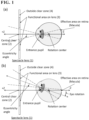
- FIG. 1 is a schematic side view illustrating a state in which the light beam passing through the central clear area 2 and the light beam passing through the functional area 3 of the spectacle lens 1 according to one aspect of the present invention, enter into a defocus sensitive area.
- the defocus area disclosed in Patent document 4 provides a defocus stimulus on the retina. Utilizing this principle, the spectacle lens disclosed in Patent document 4 provides the effect of suppressing the progression of myopia or the effect of reducing hyperopia.
- the functional area 3 covers a range where the defocus stimulus on the retina is effective, and needs to have a size that covers a certain degree of rotation angle in consideration of an eye rotation ( FIG. 1(b) ).
- the outer clear area 4 In order to improve the quality of a daily life described above, it is conceivable to design the outer clear area 4 to be large and to design the functional area 3 to be correspondingly small. However, when the functional area 3 is designed small, naturally, the effect of suppressing the progression of myopia or the effect of reducing hyperopia may be reduced.
- the light beam that enters the area other than the defocus sensitive area may be a light beam that passes through the base area 3b.
- the present inventor found that the outer clear area 4 is arranged as close to the eye point EP as possible, while providing the outer clear area 4 on the outer edge side of the functional area 3.
- the present inventor conceived of a configuration in which the retinal non-convergence area 3a is intensively provided within the functional area 3 of an entire spectacle lens 1.
- the "defocus sensitive area” is a range equal to or lower than a value of the eccentricity angles between 5 and 15 degrees of an eyeball, and is the area surrounding a macula on the retina of a wearer.
- the functional area 3 is provided on the spectacle lens 1, which sets a maximum angle of an eyeball rotation and covers the "retinal defocus sensitive area" even in a rotated state. Then, the outer clear area 4 is provided at a position where the light beam enters into a range of rotation angles exceeding the above-described one value.
- the spectacle lens always has a hidden mark so that a wearer can determine a position on the spectacle lens through which the line of sight passes in front view. Therefore, the wearer's line of sight in front view from the lens can be specified. Therefore, the radius when the center is set as a point on the lens through which the line of sight passes in front view, can be expressed as the rotation angle. Further, the rotation angle of the eye and a corresponding positional relationship on the spectacle lens are described in, for example, Japanese Patent No. 2131365 and Japanese Patent Application Laid-Open No. 2016-26324 .
- the maximum angle of eyeball rotation is set to any one value of 10 to 20 degrees
- the maximum visual angle (eccentricity angle) of the defocus sensitive area is set to any one value of 5 to 15 degrees
- a specific example of an approximate correspondence between the above values and the dimensions of the spectacle lens 1 in planar view is shown in the following manner. "In one aspect of the present invention, in planar view, the functional area 3 falls within a circle centered on the eye point EP and having a diameter that is any one value of 15.00 to 25.00 mm.”
- the functional area 3 is enclosed in a circle centered on the eye point EP and having a diameter of 25.00 mm at most.
- the diameter of a circumscribed circle of the functional area 3 may be any one value of 15.00 to 25.00 mm.
- the outer clear area 4 is arranged on the outer edge side of the functional area 3.
- the distance from the eyepoint EP in the functional area 3 is not larger than before, and the outer clear area 4 is arranged on the outer edge side of the functional area 3. As a result, it becomes easier to obtain good visibility even when paying attention to the peripheral vision.
- the area of the retinal non-convergence area 3a provided in the functional area 3 relative to the area of the retinal non-convergence area 3a in the entire spectacle lens 1 is preferably 80% or more.
- This definition is also a specific example of "a configuration in which the retinal non-convergence region 3a is provided intensively within the functional region 3 of the entire spectacle lens 1".
- the area ratio is preferably in an order of 85% or more, 90% or more, 95% or more, 98% or more, and 99% or more.
- the shape of the outer edge side of the functional area 3 (that is, the shape of the functional area 3 side in the outer clear area 4 and a boundary between the two) is preferably defined in the following manner.
- an envelope EL1 surrounding an aggregate of all circles with a radius r1 [mm] (r1 is any one value in the range of 1.5 or more and 2.50 or less) (all having the same radius) that can circumscribe the retinal non-convergence area 3a on the outer clear area 4 side within the functional area 3 without including the other retinal non-convergence area 3a, may be used as a boundary line between the functional area 3 and the outer clear area 4 (definition of the outer edge side of the functional area 3). Since the value of r1 ⁇ 2 (and r2 ⁇ 2 described below) is assumed to be a pupil diameter, each of these circles is also referred to as a clear pupil circle in this specification.
- the outer clear area 4 may be shaped as the "aggregate of clear pupil circles" instead of the envelope surrounding the aggregate of clear pupil circles.
- the outer clear area 4 may include the eye point EP and comprise the aggregate of clear pupil circles.
- an area other than the central clear area 2 and the outer clear area 4 may be defined as the functional area 3.
- the functional area 3 falls within a circle centered on the eye point EP and having a diameter that is any one value of 15.00 to 25.00 mm.
- the one value is preferably 23.00mm, 22.00mm, 21.00mm, 20.00mm.
- the functional area 3 falls within a circle centered on the eye point EP and having a diameter of 22.00 mm.
- the shape of the center side of the functional area 3 (that is, the shape of the central clear area 2) is preferably defined in the following manner.
- the central clear area 2 has a size that includes a circle centered on the eye point EP and having a diameter of 4.00 mm or more and less than 13.00 mm (preferably 6.30 mm or more and less than 7.50 mm), and has a size of falling within a circle with a diameter of another value larger than the above one value and exceeding 4.00 mm and 13.00 mm or less (preferably exceeding 6.30 mm and 7.50 mm or less) (definition of the center side of the functional area 3).
- the central clear area 1 may be shaped as the "aggregate of clear pupil circles" instead of the envelope surrounding the aggregate of clear pupil circles.
- the central clear area 2 may include the eye point EP and may comprise the aggregate of clear pupil circles.
- the diameters of both the inscribed circle and circumscribed circle of the central clear area 2 fall within a range of 4.00 to 13.00 mm. It is preferable that the central clear area 2 has such a size.
- the central clear area 2 There is no limit to the size and shape of the central clear area 2, and the shape may be circular, rectangular, elliptical, etc.
- One guideline for the lower limit of the size of the central clear area 2 is that it should be large enough to include a circle with a diameter of 4.00 mm centered on the eye point EP.
- One guideline for the upper limit of the size of the central clear area 2 is that it should be within a circle with a diameter of 13.00 mm centered on the eye point EP.
- the annular functional area 3 comprises a plurality of convex areas 3a (i.e. retinal non-convergence areas 3a) on a base area 3b having the same shape as the central clear area 2 or the outer clear area 4.
- the present invention is not limited to this embodiment.
- annular areas having a surface shape of an opaque one that has been treated like frosted glass or having an internal embedding structure may be considered as the functional area 3.
- One guideline is that in the functional area 3, it may be defined that 30% or more (or 40% or more, 50% or more, or 60% or more) of the light beam entering into the wearer's pupil is not allowed to converge on the retina.
- 30% or more (or 40% or more, 50% or more, or 60% or more) of the light beam entering into the wearer's pupil is not allowed to converge on the retina.
- the value of the percentage may be appropriately determined in consideration of the effect of suppressing the progression of myopia or the effect of reducing hyperopia and visibility.
- An upper limit may be, for example, 70%.
- the area of the retinal non-convergence area 3a (convex area 3a, embedding structure) having a configuration that exhibits the effect of suppressing the progression of myopia or the effect of reducing hyperopia in planar view, may be defined as 20% or more and 80% or less of an entire functional area 3.
- the retinal non-convergence areas 3a may be arranged sparsely toward an outer edge of the functional area 3.
- the area of the retinal non-convergence area 3a provided within the functional area 3 relative to the area of an entire spectacle lens 1, is preferably 20% or less (or 15% or less, 10% or less).
- a lower limit is 5% or more.
- the shape of the functional area 3 is not limited, and may be annular in planar view.
- the ring may be circular, rectangular, elliptical, etc., on the inside (i.e. a boundary between the central clear area 2 and the functional area 3) and/or outside (i.e. a boundary between the outer clear area 4 and the functional area 3), or a combination thereof.
- the spectacle lens 1 may be the spectacle lens 1 after being fitted into a frame, and a part of the functional area 3 of the spectacle lens 1 may be in contact with the outer edge of the spectacle lens 1, and another part of the functional area 3 may be in contact with the outer clear area 4. Further, it is acceptable to provide the retinal non-convergence area 3a further on the outer edge side of the outer clear area 4.
- a characteristic aspect of the present invention is that the retinal non-convergence region 3a is provided intensively within the functional region 3 of the entire spectacle lens 1.
- the retinal non-convergence area 3a is not provided in the outer clear area 4 on the outer edge side of the functional area 3 (preferably between the outer edge of the functional area 3 and the outer edge of the spectacle lens 1).
- the manner of arranging the defocus areas is not particularly limited, and can be determined from the viewpoints of external visibility of the defocus area, design enhancement by the defocus area, refractive power adjustment by the defocus area, etc., for example.
- the defocus area is an example of the retinal non-convergence area, in which the light beam is allowed to converge on the front side (+Z direction side) of the retina while being not allowed to converge on the retina.
- approximately circular defocus areas may be arranged in the form of islands (that is, not adjacent to each other but spaced apart) at equal intervals in a circumferential direction and a radial direction.
- the convex areas 3a are arranged independently and sparsely such that the center of each convex area 3a becomes the vertex of an equilateral triangle (the center of each defocus area is placed at the vertex of a honeycomb structure: hexagonal arrangement).
- the distance between the defocus areas may be 1.0 to 2.0 mm.
- the number of defocus areas (and eventually the retinal non-convergence areas) may be 10 to 200.
- the defocus area is an example of the configuration (retinal non-convergence area) that exhibits the effect of suppressing the progression of myopia or the effect of reducing hyperopia.
- the defocus area is the area in which at least a part of the area does not allow light to be focused at a position where the light should be focused by the base area 3b, from a geometrical optics perspective.
- the defocus area is a portion corresponding to a minute convex portion of Patent document 1.
- the spectacle lens 1 according to one aspect of the present invention is a myopia progression suppressing lens, similar to the spectacle lens described in Patent document 1. Similar to the minute convex portion of Patent document 1, the plurality of defocus areas according to one aspect of the present invention may be formed on at least one of the object-side surface and the eyeball-side surface of the spectacle lens 1.
- This specification mainly shows a case where a plurality of defocus areas are provided only on the obj ect-side surface of the spectacle lens 1.
- the defocus area has a curved shape protruding toward the outside of the lens will be shown as an example.
- half or more of the plurality of defocus areas are arranged at the same period in planar view.
- An example of a pattern of the same period is an equilateral triangular arrangement (the center of the defocus area is placed at the vertex of an equilateral triangle net; hexagonal arrangement is also acceptable) in planar view.
- the direction of the period may be a circumferential direction and/or a radial direction, and the percentage of the defocus areas is preferably 80% or more, more preferably 90% or more, even more preferably 95% or more.
- the defocus area may have a spherical shape, an aspherical shape, a toric surface shape, or a mixture thereof (for example, a central location of each defocus area has a spherical shape, and a peripheral location outside the central location has an aspherical shape).
- a boundary between the central location and the peripheral location may be provided at 1/3 to 2/3 of a radius of the defocus area (or convex area 3a) in planar view.
- it is preferable that at least the central location of the defocus area (or convex area 3a) has a convex curved shape that protrudes toward the outside of the lens.
- the defocus areas are preferably spherical.
- Each defocus area is configured as follows, for example.
- a diameter of the defocus area in planar view is preferably about 0.6 to 2.0 mm.
- a surface area of each may be approximately 0.50 to 3.14 mm 2 .
- the convex area 3a has a spherical radius of curvature of 50 to 250 mm, preferably approximately 86 mm.
- a minimum value of the defocus power provided by the defocus area on the spectacle lens 1 is within a range of 0.50 to 4.50D, and a maximum value thereof is within a range of 3.00 to 10.00D.
- a difference between the maximum value and the minimum value is within a range of 1.00 to 5.00D.
- Defocus power refers to a difference between a refractive power of each defocus area and a refractive power of a portion other than each defocus area.
- the "defocus power” is a difference obtained by subtracting the refractive power of the base portion from an average value of the minimum refractive power and maximum refractive power at a predetermined location in the defocus area. For example, this specification shows a case where the defocus area is the convex area 3a.
- the “refractive power” in this specification refers to an average refractive power that is an average value of the refractive power in a direction where the refractive power is minimum and the refractive power in a direction where the refractive power is maximum (perpendicular to the direction where the refractive power is minimum).
- a lens base material comprises thermosetting resin material such as thiourethane, allyl, acrylic, or epithio.
- resin material of the lens base material other resin material that provides a desired degree of refraction may be selected.
- the lens base material may comprise inorganic glass instead of the resin material.
- a hard coat film is formed using, for example, a thermoplastic resin or a UV curable resin.
- the hard coat film can be formed by immersing the lens base material in a hard coat liquid, or using spin coating, or the like. By coating with such a hard coat film, the durability of the spectacle lens 1 can be improved.
- An antireflection film is formed by, for example, depositing an antireflection agent such as ZrO 2 MgF 2 , Al 2 O 3 , etc., by vacuum deposition. By coating with such an antireflection film, improvement of the visibility of the image transmitted through the spectacle lens 1 is achieved.
- an antireflection agent such as ZrO 2 MgF 2 , Al 2 O 3 , etc.
- a plurality of defocus areas are formed on the object-side surface of the lens base material. Accordingly, when that surface is coated with a hard coat film and an anti-reflection film, a plurality of defocus areas are formed by the hard coat film and the antireflection film, following the defocus areas in the lens base material.
- the lens base material is molded by a known molding method such as cast polymerization. For example, by performing molding by cast polymerization using a mold having a molding surface with a plurality of recesses, a lens base material having defocus areas on at least one surface can be obtained.
- the hard coat film is then formed on the surface of the lens base material.
- the hard coat film can be formed by immersing the lens base material in a hard coat liquid, or using spin coating, or the like.
- the antireflection film is further formed on the surface of the hard coat film.
- the antireflection film can be formed by depositing a raw material for the film by vacuum evaporation.
- the spectacle lens 1 having a plurality of defocus areas on the object-side surface in such a manner as protruding toward the object side, can be obtained.
- the thickness of the film coating through the above procedure may be, for example, in a range of 0.1 to 100 ⁇ m (preferably 0.5 to 5.0 ⁇ m, more preferably 1.0 to 3.0 ⁇ m). However, the thickness of the film coating is determined depending on a function required of the film coating, and is not limited to the above range.
- One or more layers can also be formed on the film coating.
- film coatings include various coatings such as an antireflection coating, water-repellent or hydrophilic antifouling coating, and antifogging coating.
- Known techniques can be applied to the method of forming these coatings.
- a technical idea of the present invention is also reflected in spectacles fitted into a frame, with the vicinity of the periphery of the spectacle lens 1 cut.
- the frame may be full rim, half rim, under rim, or rimless.
- the spectacle lens 1 according to one aspect of the present invention will be shown.
- the present invention is not limited to the following specific examples.
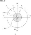
- FIG. 2 is a schematic plan view of ⁇ Specific example 1> of a spectacle lens according to one aspect of the present invention.
- the following spectacle lens 1 was produced.
- the spectacle lens 1 consists of only a lens base material, and no other material is laminated to the lens base material.
- S sinherical refractive power
- C astigmatic refractive power
- the range of the central clear area 2 was set as a circular area with a radius of 3.50 mm from the eye point EP
- the range of the functional area 3 was set as a circle with a radius of 12.50 mm from the lens center (excluding the central clear area 2)
- the outer clear area 4 was provided closer to the outer edge of the spectacle lens 1 than the functional area 3.
- An entire area between the outer edge of the spectacle lens 1 and the functional area 3 is an outer clear area 4 (the same applies to each of the following specific examples).
- the functional area 3 of this specific example is assumed to have been subjected to an opaque process such as frosted glass over an entire functional area 3.
- the functional area 3 may be an annular area including a base area 3b and having a configuration intended to provide an effect of suppressing the progression of myopia or the effect of reducing hyperopia (example: defocus area, convex area 3a and/or concave area, embedding structure, etc.).
- FIG. 3 is a schematic plan view of ⁇ Specific example 2> of a spectacle lens according to one aspect of the present invention.
- the area other than the convex area 3a is the base area 3b.
- the range of the central clear area 2 was set as a circular area with a radius of 3.45 mm from the eye point EP, and the range of the functional area 3 was set within a circle with a radius of 10.00 mm from the center of the lens (excluding the central clear area 2).
- FIG. 4 is a schematic plan view of ⁇ Specific example 3> of a spectacle lens according to one aspect of the present invention.
- the arrangement of the convex area 3a in planar view was changed. Specifically, the convex areas 3a were aligned in horizontal and vertical directions. The pitch between the convex areas 3a (the distance between the centers of the convex areas 3a) was set to 1.25 mm.
- the range of the central clear area 2 was set as a circular area with a radius of 3.25 mm from the eye point EP, and the range of the functional area 3 was set as a circle with a radius of 10.00 mm from the center of the lens (excluding the central clear area 2).
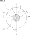
- FIG. 5 is a schematic plan view of ⁇ Specific example 4> of a spectacle lens according to one aspect of the present invention.
- the arrangement of the convex area 3a in planar view was changed. Specifically, the convex areas 3a were aligned in the circumferential direction. This alignment was made for each diameter (for each distance from the eyepoint EP). An alignment status is shown in the table below.
- the ring number is a number assigned to a circumferentially aligned group of the convex areas 3a in an order of closest to the eye point EP, and a radius is a radius of the ring, and the number of convex areas 3a is the number of convex areas 3a arranged on the ring.
- Ring number Radius (mm) The number of convex areas 1 3.84 16 2 5.27 22 3 6.70 28 4 8.13 34 5 9.56 40
- the range of the central clear area 2 was set as a circular area with a radius of 3.35 mm from the eye point EP, and the range of the functional area 3 was set as a circle with a radius of 10.06 mm from the center of the lens (excluding the central clear area 2).
Landscapes
- Health & Medical Sciences (AREA)
- Ophthalmology & Optometry (AREA)
- Physics & Mathematics (AREA)
- General Health & Medical Sciences (AREA)
- General Physics & Mathematics (AREA)
- Optics & Photonics (AREA)
- Eyeglasses (AREA)
Applications Claiming Priority (3)
| Application Number | Priority Date | Filing Date | Title |
|---|---|---|---|
| JP2021150385 | 2021-09-15 | ||
| JP2022033290A JP7177959B1 (ja) | 2021-09-15 | 2022-03-04 | 眼鏡レンズ |
| PCT/JP2022/030172 WO2023042573A1 (ja) | 2021-09-15 | 2022-08-05 | 眼鏡レンズ |
Publications (2)
| Publication Number | Publication Date |
|---|---|
| EP4403984A1 true EP4403984A1 (de) | 2024-07-24 |
| EP4403984A4 EP4403984A4 (de) | 2025-09-10 |
Family
ID=84178872
Family Applications (1)
| Application Number | Title | Priority Date | Filing Date |
|---|---|---|---|
| EP22869721.5A Pending EP4403984A4 (de) | 2021-09-15 | 2022-08-05 | Brillenglas |
Country Status (6)
| Country | Link |
|---|---|
| US (1) | US20240345419A1 (de) |
| EP (1) | EP4403984A4 (de) |
| JP (1) | JP7177959B1 (de) |
| KR (1) | KR20240021302A (de) |
| CN (1) | CN117836701A (de) |
| WO (1) | WO2023042573A1 (de) |
Families Citing this family (3)
| Publication number | Priority date | Publication date | Assignee | Title |
|---|---|---|---|---|
| JP2025002298A (ja) | 2023-06-22 | 2025-01-09 | ホヤ レンズ タイランド リミテッド | 眼鏡、および、眼鏡レンズ |
| WO2025187120A1 (ja) * | 2024-03-04 | 2025-09-12 | ホヤ レンズ タイランド リミテッド | 眼鏡レンズ |
| KR102887919B1 (ko) * | 2024-09-13 | 2025-11-18 | 한미스위스광학 주식회사 | 근시 억제 및 개선이 가능한 안경렌즈 |
Family Cites Families (25)
| Publication number | Priority date | Publication date | Assignee | Title |
|---|---|---|---|---|
| JPH02131365A (ja) | 1988-11-08 | 1990-05-21 | Kikusui Denshi Kogyo Kk | 電源回路 |
| BRPI0617356B1 (pt) * | 2005-10-12 | 2018-02-14 | Carl Zeiss Vision Australia Holdings Limited | elemento de lente oftálmica, método e sistema para dispensar ou projetar um elemento de lente oftálmica para corrigir miopia em um olho do usuário |
| US8950860B2 (en) * | 2010-09-09 | 2015-02-10 | The Hong Kong Polytechnic University | Method and system for retarding the progression of myopia |
| CN203616536U (zh) * | 2013-11-22 | 2014-05-28 | 褚仁远 | 镜片及包括其的眼镜 |
| JP7109190B2 (ja) | 2015-03-27 | 2022-07-29 | アジレント・テクノロジーズ・インク | 生細胞の統合された代謝ベースラインおよび代謝能を決定するための方法およびシステム |
| US11061255B2 (en) * | 2015-06-23 | 2021-07-13 | Johnson & Johnson Vision Care, Inc. | Ophthalmic lens comprising lenslets for preventing and/or slowing myopia progression |
| JP2016026324A (ja) | 2015-10-05 | 2016-02-12 | イーエイチエス レンズ フィリピン インク | 眼鏡用レンズ、眼鏡、眼鏡レンズの設計方法、及び設計装置 |
| US10268050B2 (en) * | 2015-11-06 | 2019-04-23 | Hoya Lens Thailand Ltd. | Spectacle lens |
| EP3532891A4 (de) * | 2016-10-25 | 2020-04-29 | Brien Holden Vision Institute Limited | Vorrichtungen, systeme und/oder verfahren zur kontrolle von kurzsichtigkeit |
| EP3730236B1 (de) * | 2017-12-18 | 2023-09-27 | Proterial, Ltd. | Generativ gefertigter gegenstand und verfahren zu seiner herstellung |
| US10884264B2 (en) | 2018-01-30 | 2021-01-05 | Sightglass Vision, Inc. | Ophthalmic lenses with light scattering for treating myopia |
| US11899286B2 (en) * | 2018-03-01 | 2024-02-13 | Essilor International | Lens element |
| EP3561578A1 (de) * | 2018-04-26 | 2019-10-30 | Essilor International (Compagnie Generale D'optique) | Linsenelement |
| WO2020004550A2 (ja) * | 2018-06-29 | 2020-01-02 | ホヤ レンズ タイランド リミテッド | 眼鏡レンズ |
| NZ771500A (en) * | 2018-07-12 | 2023-05-26 | Sightglass Vision Inc | Methods and devices for reducing myopia in children |
| EP3845956A4 (de) | 2018-08-31 | 2022-06-08 | Hoya Lens Thailand Ltd. | Brillenglas, verfahren zur herstellung eines brillenglases und brillenglasbeschichtung |
| WO2020180817A1 (en) * | 2019-03-01 | 2020-09-10 | Sightglass Vision, Inc. | Ophthalmic lenses for reducing myopic progression and methods of making the same |
| JP7657519B2 (ja) * | 2019-06-25 | 2025-04-07 | ホヤ レンズ タイランド リミテッド | 眼鏡レンズおよびその設計方法 |
| BR112021026412A2 (pt) * | 2019-06-28 | 2022-04-12 | Brien Holden Vision Institute Ltd | Lentes oftálmicas e métodos para corrigir, retardar, reduzir e/ou controlar a progressão da miopia |
| CN114787694B (zh) * | 2019-08-23 | 2024-12-10 | 华柏恩视觉研究中心有限公司 | 用于减少、最小化和/或消除失焦光对聚焦图像的干扰的眼科镜片 |
| WO2021056058A1 (en) * | 2019-09-25 | 2021-04-01 | Nthalmic Holding Pty Ltd | Apparatus and methods of spectacle solutions for myopia |
| BR112022000943A2 (pt) * | 2019-10-07 | 2022-06-28 | Essilor Int | Caracterização de um elemento óptico |
| CN110618542B (zh) * | 2019-11-05 | 2024-11-15 | 包松养 | 一种能够调节眼部肌肉的眼镜片 |
| JP7402675B2 (ja) * | 2019-12-23 | 2023-12-21 | ホヤ レンズ タイランド リミテッド | 眼鏡レンズ |
| EP4006624B1 (de) * | 2020-11-26 | 2024-04-24 | Carl Zeiss Vision International GmbH | Brillenglas design, brillenglas kit und herstllungsmethod eines brillenglases zur behandlung der fortschreitenden kurzsichtigkeit |
-
2022
- 2022-03-04 JP JP2022033290A patent/JP7177959B1/ja active Active
- 2022-08-05 WO PCT/JP2022/030172 patent/WO2023042573A1/ja not_active Ceased
- 2022-08-05 US US18/681,631 patent/US20240345419A1/en active Pending
- 2022-08-05 KR KR1020247001614A patent/KR20240021302A/ko active Pending
- 2022-08-05 CN CN202280056126.3A patent/CN117836701A/zh active Pending
- 2022-08-05 EP EP22869721.5A patent/EP4403984A4/de active Pending
Also Published As
| Publication number | Publication date |
|---|---|
| CN117836701A (zh) | 2024-04-05 |
| EP4403984A4 (de) | 2025-09-10 |
| KR20240021302A (ko) | 2024-02-16 |
| JP2023043134A (ja) | 2023-03-28 |
| WO2023042573A1 (ja) | 2023-03-23 |
| JP7177959B1 (ja) | 2022-11-24 |
| US20240345419A1 (en) | 2024-10-17 |
Similar Documents
| Publication | Publication Date | Title |
|---|---|---|
| EP4403984A1 (de) | Brillenglas | |
| JP7358619B2 (ja) | 眼鏡レンズ | |
| CN218240584U (zh) | 点阵扩散型离焦眼镜片及眼镜 | |
| US20250271687A1 (en) | Lens element, optical lens group, mold, and spectacles | |
| CN217718323U (zh) | 一种眼镜片及眼镜 | |
| WO2021181885A1 (ja) | 眼鏡レンズ | |
| US20250180924A1 (en) | Method for designing spectacle lens, method for manufacturing spectacle lens, spectacle lens, and eyeglasses | |
| CN218068482U (zh) | 一种散光离焦眼镜片及眼镜 | |
| EP4560384A1 (de) | Entwurfsverfahren für brillenglas, herstellungsverfahren für brillenglas, brillenglas und brille | |
| EP4403983A1 (de) | Brillenglas | |
| AU2022444028B2 (en) | Eyeglass lens, eyeglass lens manufacturing method, eyeglass lens design method, eyeglasses, and eyeglass manufacturing method | |
| JP2025139229A (ja) | 眼鏡レンズ及び眼鏡レンズの設計方法 | |
| WO2025191922A1 (ja) | 眼鏡レンズ | |
| WO2025037572A1 (ja) | 眼鏡レンズ及び眼鏡 | |
| CN121620725A (zh) | 眼镜镜片和眼镜 | |
| WO2025187120A1 (ja) | 眼鏡レンズ |
Legal Events
| Date | Code | Title | Description |
|---|---|---|---|
| STAA | Information on the status of an ep patent application or granted ep patent |
Free format text: STATUS: THE INTERNATIONAL PUBLICATION HAS BEEN MADE |
|
| PUAI | Public reference made under article 153(3) epc to a published international application that has entered the european phase |
Free format text: ORIGINAL CODE: 0009012 |
|
| STAA | Information on the status of an ep patent application or granted ep patent |
Free format text: STATUS: REQUEST FOR EXAMINATION WAS MADE |
|
| 17P | Request for examination filed |
Effective date: 20240206 |
|
| AK | Designated contracting states |
Kind code of ref document: A1 Designated state(s): AL AT BE BG CH CY CZ DE DK EE ES FI FR GB GR HR HU IE IS IT LI LT LU LV MC MK MT NL NO PL PT RO RS SE SI SK SM TR |
|
| DAV | Request for validation of the european patent (deleted) | ||
| DAX | Request for extension of the european patent (deleted) | ||
| A4 | Supplementary search report drawn up and despatched |
Effective date: 20250812 |
|
| RIC1 | Information provided on ipc code assigned before grant |
Ipc: G02C 7/06 20060101AFI20250806BHEP Ipc: G02C 7/00 20060101ALI20250806BHEP Ipc: G02C 7/02 20060101ALI20250806BHEP Ipc: G02C 7/16 20060101ALI20250806BHEP |