EP4403950A1 - Lamp device - Google Patents
Lamp device Download PDFInfo
- Publication number
- EP4403950A1 EP4403950A1 EP22883250.7A EP22883250A EP4403950A1 EP 4403950 A1 EP4403950 A1 EP 4403950A1 EP 22883250 A EP22883250 A EP 22883250A EP 4403950 A1 EP4403950 A1 EP 4403950A1
- Authority
- EP
- European Patent Office
- Prior art keywords
- obstacle detection
- lamp
- detection unit
- translucent cover
- transmitting
- Prior art date
- Legal status (The legal status is an assumption and is not a legal conclusion. Google has not performed a legal analysis and makes no representation as to the accuracy of the status listed.)
- Pending
Links
Images



Classifications
-
- G—PHYSICS
- G01—MEASURING; TESTING
- G01S—RADIO DIRECTION-FINDING; RADIO NAVIGATION; DETERMINING DISTANCE OR VELOCITY BY USE OF RADIO WAVES; LOCATING OR PRESENCE-DETECTING BY USE OF THE REFLECTION OR RERADIATION OF RADIO WAVES; ANALOGOUS ARRANGEMENTS USING OTHER WAVES
- G01S7/00—Details of systems according to groups G01S13/00, G01S15/00, G01S17/00
- G01S7/48—Details of systems according to groups G01S13/00, G01S15/00, G01S17/00 of systems according to group G01S17/00
- G01S7/481—Constructional features, e.g. arrangements of optical elements
-
- F—MECHANICAL ENGINEERING; LIGHTING; HEATING; WEAPONS; BLASTING
- F21—LIGHTING
- F21S—NON-PORTABLE LIGHTING DEVICES; SYSTEMS THEREOF; VEHICLE LIGHTING DEVICES SPECIALLY ADAPTED FOR VEHICLE EXTERIORS
- F21S41/00—Illuminating devices specially adapted for vehicle exteriors, e.g. headlamps
- F21S41/20—Illuminating devices specially adapted for vehicle exteriors, e.g. headlamps characterised by refractors, transparent cover plates, light guides or filters
- F21S41/2805—Cover glass
-
- B—PERFORMING OPERATIONS; TRANSPORTING
- B60—VEHICLES IN GENERAL
- B60Q—ARRANGEMENT OF SIGNALLING OR LIGHTING DEVICES, THE MOUNTING OR SUPPORTING THEREOF OR CIRCUITS THEREFOR, FOR VEHICLES IN GENERAL
- B60Q1/00—Arrangement of optical signalling or lighting devices, the mounting or supporting thereof or circuits therefor
- B60Q1/0017—Devices integrating an element dedicated to another function
- B60Q1/0023—Devices integrating an element dedicated to another function the element being a sensor, e.g. distance sensor, camera
-
- B—PERFORMING OPERATIONS; TRANSPORTING
- B60—VEHICLES IN GENERAL
- B60Q—ARRANGEMENT OF SIGNALLING OR LIGHTING DEVICES, THE MOUNTING OR SUPPORTING THEREOF OR CIRCUITS THEREFOR, FOR VEHICLES IN GENERAL
- B60Q1/00—Arrangement of optical signalling or lighting devices, the mounting or supporting thereof or circuits therefor
- B60Q1/02—Arrangement of optical signalling or lighting devices, the mounting or supporting thereof or circuits therefor the devices being primarily intended to illuminate the way ahead or to illuminate other areas of way or environments
- B60Q1/04—Arrangement of optical signalling or lighting devices, the mounting or supporting thereof or circuits therefor the devices being primarily intended to illuminate the way ahead or to illuminate other areas of way or environments the devices being headlights
-
- G—PHYSICS
- G01—MEASURING; TESTING
- G01S—RADIO DIRECTION-FINDING; RADIO NAVIGATION; DETERMINING DISTANCE OR VELOCITY BY USE OF RADIO WAVES; LOCATING OR PRESENCE-DETECTING BY USE OF THE REFLECTION OR RERADIATION OF RADIO WAVES; ANALOGOUS ARRANGEMENTS USING OTHER WAVES
- G01S13/00—Systems using the reflection or reradiation of radio waves, e.g. radar systems; Analogous systems using reflection or reradiation of waves whose nature or wavelength is irrelevant or unspecified
- G01S13/88—Radar or analogous systems specially adapted for specific applications
- G01S13/93—Radar or analogous systems specially adapted for specific applications for anti-collision purposes
- G01S13/931—Radar or analogous systems specially adapted for specific applications for anti-collision purposes of land vehicles
-
- G—PHYSICS
- G01—MEASURING; TESTING
- G01S—RADIO DIRECTION-FINDING; RADIO NAVIGATION; DETERMINING DISTANCE OR VELOCITY BY USE OF RADIO WAVES; LOCATING OR PRESENCE-DETECTING BY USE OF THE REFLECTION OR RERADIATION OF RADIO WAVES; ANALOGOUS ARRANGEMENTS USING OTHER WAVES
- G01S17/00—Systems using the reflection or reradiation of electromagnetic waves other than radio waves, e.g. lidar systems
- G01S17/88—Lidar systems specially adapted for specific applications
- G01S17/93—Lidar systems specially adapted for specific applications for anti-collision purposes
- G01S17/931—Lidar systems specially adapted for specific applications for anti-collision purposes of land vehicles
-
- G—PHYSICS
- G01—MEASURING; TESTING
- G01S—RADIO DIRECTION-FINDING; RADIO NAVIGATION; DETERMINING DISTANCE OR VELOCITY BY USE OF RADIO WAVES; LOCATING OR PRESENCE-DETECTING BY USE OF THE REFLECTION OR RERADIATION OF RADIO WAVES; ANALOGOUS ARRANGEMENTS USING OTHER WAVES
- G01S7/00—Details of systems according to groups G01S13/00, G01S15/00, G01S17/00
- G01S7/02—Details of systems according to groups G01S13/00, G01S15/00, G01S17/00 of systems according to group G01S13/00
- G01S7/027—Constructional details of housings, e.g. form, type, material or ruggedness
-
- G—PHYSICS
- G01—MEASURING; TESTING
- G01S—RADIO DIRECTION-FINDING; RADIO NAVIGATION; DETERMINING DISTANCE OR VELOCITY BY USE OF RADIO WAVES; LOCATING OR PRESENCE-DETECTING BY USE OF THE REFLECTION OR RERADIATION OF RADIO WAVES; ANALOGOUS ARRANGEMENTS USING OTHER WAVES
- G01S7/00—Details of systems according to groups G01S13/00, G01S15/00, G01S17/00
- G01S7/48—Details of systems according to groups G01S13/00, G01S15/00, G01S17/00 of systems according to group G01S17/00
- G01S7/481—Constructional features, e.g. arrangements of optical elements
- G01S7/4811—Constructional features, e.g. arrangements of optical elements common to transmitter and receiver
- G01S7/4813—Housing arrangements
-
- G—PHYSICS
- G01—MEASURING; TESTING
- G01S—RADIO DIRECTION-FINDING; RADIO NAVIGATION; DETERMINING DISTANCE OR VELOCITY BY USE OF RADIO WAVES; LOCATING OR PRESENCE-DETECTING BY USE OF THE REFLECTION OR RERADIATION OF RADIO WAVES; ANALOGOUS ARRANGEMENTS USING OTHER WAVES
- G01S13/00—Systems using the reflection or reradiation of radio waves, e.g. radar systems; Analogous systems using reflection or reradiation of waves whose nature or wavelength is irrelevant or unspecified
- G01S13/88—Radar or analogous systems specially adapted for specific applications
- G01S13/93—Radar or analogous systems specially adapted for specific applications for anti-collision purposes
- G01S13/931—Radar or analogous systems specially adapted for specific applications for anti-collision purposes of land vehicles
- G01S2013/9323—Alternative operation using light waves
-
- G—PHYSICS
- G01—MEASURING; TESTING
- G01S—RADIO DIRECTION-FINDING; RADIO NAVIGATION; DETERMINING DISTANCE OR VELOCITY BY USE OF RADIO WAVES; LOCATING OR PRESENCE-DETECTING BY USE OF THE REFLECTION OR RERADIATION OF RADIO WAVES; ANALOGOUS ARRANGEMENTS USING OTHER WAVES
- G01S13/00—Systems using the reflection or reradiation of radio waves, e.g. radar systems; Analogous systems using reflection or reradiation of waves whose nature or wavelength is irrelevant or unspecified
- G01S13/88—Radar or analogous systems specially adapted for specific applications
- G01S13/93—Radar or analogous systems specially adapted for specific applications for anti-collision purposes
- G01S13/931—Radar or analogous systems specially adapted for specific applications for anti-collision purposes of land vehicles
- G01S2013/9327—Sensor installation details
- G01S2013/93271—Sensor installation details in the front of the vehicles
-
- G—PHYSICS
- G01—MEASURING; TESTING
- G01S—RADIO DIRECTION-FINDING; RADIO NAVIGATION; DETERMINING DISTANCE OR VELOCITY BY USE OF RADIO WAVES; LOCATING OR PRESENCE-DETECTING BY USE OF THE REFLECTION OR RERADIATION OF RADIO WAVES; ANALOGOUS ARRANGEMENTS USING OTHER WAVES
- G01S13/00—Systems using the reflection or reradiation of radio waves, e.g. radar systems; Analogous systems using reflection or reradiation of waves whose nature or wavelength is irrelevant or unspecified
- G01S13/88—Radar or analogous systems specially adapted for specific applications
- G01S13/93—Radar or analogous systems specially adapted for specific applications for anti-collision purposes
- G01S13/931—Radar or analogous systems specially adapted for specific applications for anti-collision purposes of land vehicles
- G01S2013/9327—Sensor installation details
- G01S2013/93277—Sensor installation details in the lights
Definitions
- the present invention relates to a lamp device, and particularly to a lamp device for a vehicle, which includes an obstacle detection device built therein.
- various sensors such as a camera, LiDAR (Light Detection and Ranging), and a millimeter wave sensor are used in addition to an acceleration sensor and a GPS sensor.
- a camera LiDAR (Light Detection and Ranging)
- a millimeter wave sensor is used in addition to an acceleration sensor and a GPS sensor.
- an obstacle detection device can directly detect the distance and direction to an object, and a relative speed with the object. Therefore, the obstacle detection device has the characteristic that even a short-range object can be detected at high speed and with high accuracy.
- the LiDAR is configured to irradiate a 1-wat-class pulse laser to an object, detect reflected light, and detect the distance from the time taken to detect the reflected light, and has a feature that laser light higher in luminous flux density than an electromagnetic wave and short in wavelength is used to make it possible to detect a position, a shape and the like with high accuracy. Elements in a near-infrared wavelength range are often used for this laser light to make it possible to achieve distance sensing and high optical resolution.
- Patent Literature 1 a vehicular lamp tool which is mounted with a light source unit and a millimeter wave radar and has a resin cover appearing on the exterior of a vehicle body, and which has an opaque design part at a part of the resin cover and shields the millimeter wave radar by the design part.
- Patent Literature 2 an in-vehicle light device which is arranged to partition a space between a lamp unit and a radar unit and is provided with a separator which shields the transmission of radiant heat and electromagnetic waves between the lamp unit and the radar unit.
- Patent Literature 3 a vehicular lamp tool in which a lamp chamber is formed between a lamp body and a front cover, a light source is provided inside the lamp chamber, a millimeter wave radar is installed outside the lamp chamber, and a shielding part covering the millimeter wave radar from the front is formed on the front cover.
- an obstacle detection device which detects the lateral direction of a vehicle is also easily affected by radiant heat of the vehicle itself such as engine heat.
- a LiDAR device such that the effect of heat from the light source of the lamp body or the effect of the radiant heat such as the engine heat is avoided by, for example, attaching the LiDAR device to other than the lamp tool and performing obstacle detection as a separate structure.
- attaching the LiDAR device to other than the lamp tool and performing obstacle detection as a separate structure.
- a structural part other than the lamp body to house the obstacle detection device is required, so that the problem of increasing the size arises.
- the present invention has been made in view of the above points, and it is an object of the present invention to provide a lamp device capable of effectively suppressing the effect of radiant heat of a vehicle itself such as engine heat and miniaturization by housing an obstacle detection device in a lamp body.
- the vehicle means a conveyance (Vehicle) including, for example, a ship, an aircraft, etc., and manned and unmanned means of transportation.
- conveyance Vehicle
- the vehicle means a conveyance (Vehicle) including, for example, a ship, an aircraft, etc., and manned and unmanned means of transportation.
- FIG. 1 is a view schematically illustrating an example of an internal structure of a lamp device 10 according to a first embodiment of the present invention,
- the lamp device 10 is mounted on a vehicle such as an automobile.
- the lamp device 10 is, for example, a headlight, but can also be applied to a lamp device having the purpose and function of emitting light toward the outside such as a taillight and a backlight.
- FIG. 1 schematically illustrates a cross section of the lamp device 10 (left headlight) in a state of being mounted on the left front of the vehicle when viewed from its upper surface, i.e., in a horizontal plane (or a plane parallel to the road surface).
- horizontal and vertical planes refer to the horizontal and vertical planes (or directions) when the lamp device 10 is mounted onto the vehicle, and correspond to the horizontal and vertical planes (or directions) of the vehicle.
- the lamp device 10 has a lamp section 11 and an obstacle detection unit 20 which is an obstacle detection part.
- a lamp housing (casing) 11C is constituted of a base 12 and a translucent cover (front cover) 13 mounted to the front surface side or front side of the base 12.
- a lamp body space 11K which is an internal space is defined by mounting the translucent cover 13 to the base 12.
- the lamp body space 11K is configured as a sealed space.
- the translucent cover 13 is mounted to the base 12 so as to cover the front surface side of the base 12.
- the lamp device 10 is mounted on a vehicle body (not illustrated) by mounting the base 12 to the vehicle body side.
- the base 12 is formed of plastic (resin).
- a headlight is formed of PP (polypropylene), and a tail lamp is formed of ASA (acrylonitrile-styrene-acrylic rubber), but they are not limited to these. Further, a metal and the like may be used partially.
- the translucent cover 13 is formed of, for example, a translucent resin such as polycarbonate (PC). Note that the translucent cover 13 may have a translucent property which allows light other than white, such as red or yellow to pass therethrough.
- a translucent resin such as polycarbonate (PC).
- PC polycarbonate
- a light source unit 14 is provided in the lamp body space 11K of the lamp housing 11C.
- the light source unit 14 includes a light source 15 such as an LED (Light Emitting Diode) and an optical system 14L such as a lens or reflector for distributing and irradiating light from the light source 15 along an optical axis AX1.
- the light source 15 is provided within a light source housing 14K.
- the light source unit 14 is provided so as to emit low beam (passing beam) and high beam (running beam) irradiation light LB in a forward (FR in the figure) direction.
- an extension or the like may be provided within the lamp housing 11C.
- the extension is a design component provided to reflect light, guide light, or make internal structures or the like difficult to see from the outside.
- the obstacle detection unit 20 is fixed to the translucent cover 13.
- the obstacle detection unit 20 is provided so as to be located on a rear surface of the translucent cover 13 and on the side of the light source unit 14 in the horizontal direction. Further, the obstacle detection unit 20 is provided at a position spaced apart from the base 12. More specifically, the obstacle detection unit 20 is provided at a position where a side wall and a bottom portion of the obstacle detection unit 20 do not contact the base 12, i.e., at a position where the base 12 does not contact the vehicle body when mounted on the vehicle body.
- the obstacle detection unit 20 has a housing 21 and an obstacle detection device 23 housed in the housing 21.
- the obstacle detection device 23 transmits electromagnetic waves such as millimeter waves or laser light and measures the distance to an object and the shape thereof by observing the electromagnetic waves reflected by the object.
- a space (obstacle detection unit space) 20K is defined which is separated from the lamp body space 11K of the lamp housing 11C by the housing 21 and separated away from the lamp body space 11K.
- the housing 21 of the obstacle detection unit 20 is fixed to the rear surface of the translucent cover 13, i.e., within the lamp body space 11K. Then, a portion 21S of the translucent cover 13 facing the obstacle detection unit 20 and the housing 21 define the obstacle detection unit space 20K.
- existing methods such as screwing, an adhesive, and welding of resins together can be selected.
- the housing 21 of the obstacle detection unit 20 may use, for example, a resin containing an electromagnetic wave absorbing material such as carbon if the electromagnetic waves are in a millimeter wave band, or a member in which the coating of the front or back surface of the housing 21 with an electromagnetic wave absorbing material or the sticking of an electromagnetic wave absorber thereon, and the like are performed.
- infrared absorbing substances such as LaB6 (lanthanum hexaboride), CWO (cesium-doped tungsten oxide), ITO (tin-doped indium oxide), and ATO (antimony-doped tin oxide) can be used as with carbon by being contained in the resin or by coating on the surface or back surface of the housing, etc.
- the obstacle detection unit 20 has the obstacle detection device 23 which is a distance detecting sensor provided in the obstacle detection unit space 20K.
- the obstacle detection device 23 is, for example, a detection and ranging device using electromagnetic waves, such as LiDAR and a radar device.
- a part of the translucent cover 13 of the lamp device 10 which faces the light source unit 14 transmits visible light
- a part thereof in which the obstacle detection unit 20 faces may be configured to transmit electromagnetic waves sent out by the obstacle detection device 23 and to be non-translucent or semi-translucent to visible light.
- the obstacle detection unit 20 is not visible from the outside, which is preferable in terms of design.
- Such a structure can be made by, for example, making the translucent cover 13 from a resin material which transmits visible light, and then fabricating the part where the obstacle detection unit 20 faces by two-color molding using a non-translucent material. Further, instead of the two-color molding, a film made of a non-translucent material may be attached to the corresponding part.
- the obstacle detection device 23 has a transmitting-receiving unit 23T and is arranged such that a central axis AX2 of an electromagnetic wave by the transmitting-receiving unit 23T is tilted in an outward direction (i.e., left direction in the case of the left headlight) by an angle ⁇ ( ⁇ >0) with respect to the optical axis AX1 of the light source unit 14 (or relative to the travelling direction FR of the vehicle).
- the range of detection by the obstacle detection device 23 may have an extension of a predetermined angle from the central axis AX2 of the electromagnetic wave. It is preferable that the location where the housing 21 is fixed to the translucent cover 13 is set outside this angular range. Therefore, it is possible to suppress degradation in detection accuracy of the obstacle detection device 23.
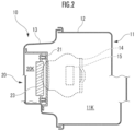
- FIG. 2 is a cross-sectional view schematically illustrating the example of the internal structure of the lamp device 10. Note that the figure illustrates a cross section (direction indicated by A in FIG. 1 ) in a vertical plane including the central axis AX2 which is a central axis of a transmitting-receiving antenna for electromagnetic waves by the transmitting-receiving unit 23T or a scanning central axis of the laser light.
- AX2 is a central axis of a transmitting-receiving antenna for electromagnetic waves by the transmitting-receiving unit 23T or a scanning central axis of the laser light.
- the obstacle detection device 23 is arranged to be located on the outer side of the light source unit 14 in the horizontal plane (i.e., on the side in the horizontal direction).
- FIG. 2 illustrates that the light source unit 14 (indicated by a broken line) is arranged behind the obstacle detection device 23.
- FIG. 3 is a view similar to FIG. 1 , but illustrates radiant heat RH from the heat source 90 such as a vehicle engine, which is mounted with the lamp device 10.
- the lamp device 10 has the lamp body space 11K which receives the radiant heat from the heat source 90 such as the engine.
- the obstacle detection unit 20 is separated by the lamp body space 11K of the lamp section 11, so that the effect of the radiant heat RH from the heat source 90 of the vehicle itself in a high temperature environment is avoided. That is, since the obstacle detection unit 20 does not come into direct contact with the heat source 90 of the vehicle itself, it is possible to reduce a rise in the temperature of the obstacle detection unit 20.
- FIG. 4 is a partially enlarged sectional view schematically illustrating a structure of a lamp device 10 according to a second embodiment of the present invention. More specifically, FIG. 4 is a view illustrating a structure of an obstacle detection unit 20 in an enlarged form.
- a part 21S of a translucent cover 13 facing a housing 21 of the obstacle detection unit 20 has communication portions 21C each being a hole portion through which the outside and an obstacle detection unit space 20K communicate. That is, the obstacle detection unit 20 is not sealed, and the obstacle detection unit space 20K which is its internal space serves as a non-sealed space. Note that it is preferable that a plurality of communication portions 21C be provided.
- the obstacle detection device 23 is mounted to a translucent cover 13 so as to have a gap between the obstacle detection device 23 and the surface of the housing 21 of the obstacle detection unit 20 (refer to FIG. 2 ).
- the obstacle detection device 23 is configured such that an air circulation path 21A is formed between the back surface of the obstacle detection device 23 and the housing 21 of the obstacle detection unit 20, and heat dissipation and cooling of a sensor operated within the obstacle detection device 23 are performed so that the effect of heat from a lamp section 11 can be reduced.
- the obstacle detection device 23 is separated by a lamp body space 11K of the lamp section 11 and is excellent even in cooling effect, and is capable of reducing the effect of radiant heat RH from a heat source 90 of a vehicle being in a high-temperature environment and preventing a rise in the temperature of the obstacle detection unit 20.
- FIG. 5 is a cross-sectional view schematically illustrating a structure of a lamp device 10 according to a third embodiment of the present invention.
- an obstacle detection unit 20 has a sealed structure and has a space separated from a lamp body space 11K. Specifically, a housing 21 of the obstacle detection unit 20 is mounted to a translucent cover 13 of a lamp section 11 through a seal portion 25, and thereby an internal space (obstacle detection unit space 20K) of the obstacle detection unit 20 is configured as a sealed space. Further, the obstacle detection unit space 20K is formed as an isolated space from which heat from the lamp body space 11K is cut off.
- a transmitting-receiving circuit board 23C which is a sensor circuit serving as an obstacle detection device is provided inside the obstacle detection unit 20. More specifically, the transmitting-receiving circuit board 23C is a circuit board on which a transmitting wave generator (generator), e.g., a transmitting-receiving circuit such as a monolithic microwave integrated circuit (MMIC) which transmits and receives electromagnetic waves such as millimeter waves and laser light, and an interface circuit are mounted. Therefore, the transmitting-receiving circuit board 23C is constructed on a circuit board excellent in heat dissipation.
- the obstacle detection device circuit board is provided so as to be exposed inside the obstacle detection unit space 20K of the obstacle detection unit 20.
- the transmitting-receiving circuit board 23C is connected to, for example, a detection device control module 27 arranged within the lamp body space 11K of the lamp section 11.
- the detection device control module 27 is provided within a light control module (LCM), for example.
- LCD light control module
- the detection device control module 27 functions as a signal processing and control circuit which performs signal processing of a detection signal from the transmitting-receiving circuit board 23C and control of the transmitting-receiving circuit board 23C. That is, the transmitting-receiving circuit board 23C and the detection device control module 27 constitute the obstacle detection unit 20.
- the detection device control module 27 is configured as a processor (for example, a CPU) and is a main heat generation body for the obstacle detection unit 20.
- the signal processing and control circuit for the detection signal of the transmitting-receiving circuit board 23C is provided outside the obstacle detection unit space 20K as the detection device control module (processor) 27.
- the detection device control module 27 which is the heat generation body is provided separately from the transmitting-receiving circuit board 23C, the heat generated within the obstacle detection unit space 20K is low. Further, since the heat generated by the transmitting-receiving circuit board 23C is radiated through the translucent cover 13, and a rise in the temperature in the obstacle detection unit space 20K is suppressed, deterioration in the characteristics of the sensor circuit due to the temperature rise is suppressed.
- the transmitting-receiving circuit board 23C of the obstacle detection device 23 which functions as the obstacle detection device sensor 23 is separated by the lamp body space 11K of the lamp section 11 and excellent even in cooling effect, and is reduced in the effect of radiant heat RH from a heat source 90 of a vehicle.
- FIG. 6 is a cross-sectional view schematically illustrating a structure of a lamp device 10 according to a fourth embodiment of the present invention.
- an obstacle detection unit 20 is fitted into and fixed to a through hole 13H provided in a part of a translucent cover 13. More specifically, a flange portion 21F formed at a peripheral edge of a housing 21 of the obstacle detection unit 20 is joined to a peripheral edge of the through hole 13H of the translucent cover 13, and the housing 21 is fixed to the translucent cover 13. Then, an obstacle detection device 23 is fixed inside the housing 21. Further, a front opening of the housing 21 of the obstacle detection unit 20 is covered with a non-translucent cover 21D.
- non-translucent cover 21D is preferably heat shielding.
- resins such as polycarbonate, acrylic, and PBT can be used. Further, it is possible to perform heat shielding and achieve weight reduction by using a foamed resin.
- the obstacle detection device 23 is separated by a lamp body space 11K of a lamp section 11, thereby making it possible to reduce the effect of radiant heat RH from a vehicle heat source 90 which is in a high-temperature environment and prevent a rise in the temperature of the obstacle detection unit 20.
- the non-translucent cover 21D can be made of, for example, a material through which electromagnetic waves transmitted by the obstacle detection device 23 can pass more easily than the translucent cover 13, thereby making it possible to improve the accuracy of obstacle detection. Further, it is possible to perform freely changing of the outer appearance color of the non-translucent cover 21D to one matched the color of a vehicle body, and the like, for example. This is preferable from a design standpoint.
- the non-translucent cover 21D and the translucent cover 13 are set so as to form a common curved surface, that is, the surface of the non-translucent cover 21D and the surface of the translucent cover 13 are set not to have a step difference therebetween, thereby making it possible to create such an outer appearance that the non-translucent cover 21D is integral with the translucent cover 13, which is preferable in terms of design.
Landscapes
- Engineering & Computer Science (AREA)
- Radar, Positioning & Navigation (AREA)
- Remote Sensing (AREA)
- Physics & Mathematics (AREA)
- Computer Networks & Wireless Communication (AREA)
- General Physics & Mathematics (AREA)
- Mechanical Engineering (AREA)
- Electromagnetism (AREA)
- General Engineering & Computer Science (AREA)
- Optical Radar Systems And Details Thereof (AREA)
- Radar Systems Or Details Thereof (AREA)
- Arrangement Of Elements, Cooling, Sealing, Or The Like Of Lighting Devices (AREA)
Abstract
Description
- The present invention relates to a lamp device, and particularly to a lamp device for a vehicle, which includes an obstacle detection device built therein.
- For driving support of automobiles and automatic driving, various sensors such as a camera, LiDAR (Light Detection and Ranging), and a millimeter wave sensor are used in addition to an acceleration sensor and a GPS sensor.
- In particular, an obstacle detection device can directly detect the distance and direction to an object, and a relative speed with the object. Therefore, the obstacle detection device has the characteristic that even a short-range object can be detected at high speed and with high accuracy. Among them, the LiDAR is configured to irradiate a 1-wat-class pulse laser to an object, detect reflected light, and detect the distance from the time taken to detect the reflected light, and has a feature that laser light higher in luminous flux density than an electromagnetic wave and short in wavelength is used to make it possible to detect a position, a shape and the like with high accuracy. Elements in a near-infrared wavelength range are often used for this laser light to make it possible to achieve distance sensing and high optical resolution.
- There has been disclosed in Patent Literature 1, a vehicular lamp tool which is mounted with a light source unit and a millimeter wave radar and has a resin cover appearing on the exterior of a vehicle body, and which has an opaque design part at a part of the resin cover and shields the millimeter wave radar by the design part.
- Further, there has been disclosed in Patent Literature 2, an in-vehicle light device which is arranged to partition a space between a lamp unit and a radar unit and is provided with a separator which shields the transmission of radiant heat and electromagnetic waves between the lamp unit and the radar unit.
- There has been disclosed in Patent Literature 3, a vehicular lamp tool in which a lamp chamber is formed between a lamp body and a front cover, a light source is provided inside the lamp chamber, a millimeter wave radar is installed outside the lamp chamber, and a shielding part covering the millimeter wave radar from the front is formed on the front cover.
-
- Patent Literature 1:
Japanese Patent No. 5130192 - Patent Literature 2:
Japanese Patent Application Laid-Open No. 2020-51974 - Patent Literature 3:
Japanese Patent No. 5285405 - However, when affected by a high temperature environment outside a lamp body such as heat generated by a lamp inside the lamp body or engine heat, the detection function of an obstacle detection device built in the lamp body is deteriorated. A main reason for this is that the junction temperature of a semiconductor device used inside the obstacle detection device becomes too high and its function is deteriorated.
- In particular, in the LiDAR, since the power of transmitted electromagnetic waves (laser light) is greater than that in millimeter wave radar, heat generation associated with this is large, and the detection function is significantly degraded. Further, an obstacle detection device which detects the lateral direction of a vehicle is also easily affected by radiant heat of the vehicle itself such as engine heat.
- Since the engine continues to function even when the lamp in the lamp body is not lit, the radiant heat from the engine is constantly applied to the obstacle detection device. Therefore, it has been desired to suppress the effect of the radiant heat from the engine.
- To solve this problem, it is conceivable to arrange a LiDAR device such that the effect of heat from the light source of the lamp body or the effect of the radiant heat such as the engine heat is avoided by, for example, attaching the LiDAR device to other than the lamp tool and performing obstacle detection as a separate structure. However, although this solves the problem of degrading the detection function due to the heat, a structural part other than the lamp body to house the obstacle detection device is required, so that the problem of increasing the size arises.
- The present invention has been made in view of the above points, and it is an object of the present invention to provide a lamp device capable of effectively suppressing the effect of radiant heat of a vehicle itself such as engine heat and miniaturization by housing an obstacle detection device in a lamp body.
- There is provided a lamp device according to one embodiment of the present invention which includes:
- a base which serves as a mounting part onto a vehicle;
- a light source unit;
- a translucent cover which covers a front surface side of the base so as to accommodate the light source unit inside and is mounted on the base to define a lamp body space; and
- an obstacle detection unit arranged at a horizontal side position of the light source unit on the lamp body space side of the translucent cover and configured to detect an obstacle by transmitting electromagnetic waves, and
- in which the obstacle detection unit includes a housing and an obstacle detection device housed in the housing, and
- the housing is fixed to the translucent cover and provided spaced away from the base.
-
-
FIG. 1 is a view schematically illustrating an example of an internal structure of alamp device 10 according to a first embodiment of the present invention; -
FIG. 2 is a cross-sectional view schematically illustrating the example of the internal structure of thelamp device 10; -
FIG. 3 is a cross-sectional view illustrating radiant heat RH from aheat source 90 of a vehicle on which thelamp device 10 is mounted; -
FIG. 4 is a cross-sectional view schematically illustrating a structure of alamp device 10 according to a second embodiment of the present invention; -
FIG. 5 is a cross-sectional view schematically illustrating a structure of alamp device 10 according to a third embodiment of the present invention; and -
FIG. 6 is a cross-sectional view schematically illustrating a structure of alamp device 10 according to a fourth embodiment of the present invention. - Although preferred embodiments of the present invention will hereinafter be described, they may be modified as appropriate or applied in combination. Also, in the following description and accompanying drawings, substantially the same or equivalent parts will be described with the same reference numerals given thereto.
- Note that although an automobile will be described below as an example of a vehicle, the present invention is not limited to this. That is, in the present specification, the vehicle means a conveyance (Vehicle) including, for example, a ship, an aircraft, etc., and manned and unmanned means of transportation.
-
FIG. 1 is a view schematically illustrating an example of an internal structure of alamp device 10 according to a first embodiment of the present invention, Thelamp device 10 is mounted on a vehicle such as an automobile. Thelamp device 10 is, for example, a headlight, but can also be applied to a lamp device having the purpose and function of emitting light toward the outside such as a taillight and a backlight. - More specifically,
FIG. 1 schematically illustrates a cross section of the lamp device 10 (left headlight) in a state of being mounted on the left front of the vehicle when viewed from its upper surface, i.e., in a horizontal plane (or a plane parallel to the road surface). - Note, in the present specification, the terms "horizontal and vertical planes (or directions) refer to the horizontal and vertical planes (or directions) when the
lamp device 10 is mounted onto the vehicle, and correspond to the horizontal and vertical planes (or directions) of the vehicle. - The
lamp device 10 has alamp section 11 and anobstacle detection unit 20 which is an obstacle detection part. In thelamp device 10, a lamp housing (casing) 11C is constituted of abase 12 and a translucent cover (front cover) 13 mounted to the front surface side or front side of thebase 12. - More, specifically, a
lamp body space 11K which is an internal space is defined by mounting thetranslucent cover 13 to thebase 12. In the present embodiment, thelamp body space 11K is configured as a sealed space. - The
translucent cover 13 is mounted to thebase 12 so as to cover the front surface side of thebase 12. Thelamp device 10 is mounted on a vehicle body (not illustrated) by mounting thebase 12 to the vehicle body side. - The
base 12 is formed of plastic (resin). For example, a headlight is formed of PP (polypropylene), and a tail lamp is formed of ASA (acrylonitrile-styrene-acrylic rubber), but they are not limited to these. Further, a metal and the like may be used partially. - Further, the
translucent cover 13 is formed of, for example, a translucent resin such as polycarbonate (PC). Note that thetranslucent cover 13 may have a translucent property which allows light other than white, such as red or yellow to pass therethrough. - A
light source unit 14 is provided in thelamp body space 11K of thelamp housing 11C. Thelight source unit 14 includes alight source 15 such as an LED (Light Emitting Diode) and anoptical system 14L such as a lens or reflector for distributing and irradiating light from thelight source 15 along an optical axis AX1. Thelight source 15 is provided within alight source housing 14K. - The
light source unit 14 is provided so as to emit low beam (passing beam) and high beam (running beam) irradiation light LB in a forward (FR in the figure) direction. - Further, an extension or the like may be provided within the
lamp housing 11C. The extension is a design component provided to reflect light, guide light, or make internal structures or the like difficult to see from the outside. - The
obstacle detection unit 20 is fixed to thetranslucent cover 13. Theobstacle detection unit 20 is provided so as to be located on a rear surface of thetranslucent cover 13 and on the side of thelight source unit 14 in the horizontal direction. Further, theobstacle detection unit 20 is provided at a position spaced apart from thebase 12. More specifically, theobstacle detection unit 20 is provided at a position where a side wall and a bottom portion of theobstacle detection unit 20 do not contact thebase 12, i.e., at a position where thebase 12 does not contact the vehicle body when mounted on the vehicle body. - The
obstacle detection unit 20 has ahousing 21 and anobstacle detection device 23 housed in thehousing 21. Theobstacle detection device 23 transmits electromagnetic waves such as millimeter waves or laser light and measures the distance to an object and the shape thereof by observing the electromagnetic waves reflected by the object. - In the
obstacle detection unit 20, a space (obstacle detection unit space) 20K is defined which is separated from thelamp body space 11K of thelamp housing 11C by thehousing 21 and separated away from thelamp body space 11K. - More specifically, the
housing 21 of theobstacle detection unit 20 is fixed to the rear surface of thetranslucent cover 13, i.e., within thelamp body space 11K. Then, aportion 21S of thetranslucent cover 13 facing theobstacle detection unit 20 and thehousing 21 define the obstacledetection unit space 20K. As a method of fixing thehousing 21 to thetranslucent cover 13, existing methods such as screwing, an adhesive, and welding of resins together can be selected. - Incidentally, in order to absorb the electromagnetic waves transmitted by the
obstacle detection device 23, thehousing 21 of theobstacle detection unit 20 may use, for example, a resin containing an electromagnetic wave absorbing material such as carbon if the electromagnetic waves are in a millimeter wave band, or a member in which the coating of the front or back surface of thehousing 21 with an electromagnetic wave absorbing material or the sticking of an electromagnetic wave absorber thereon, and the like are performed. - Further, when the electromagnetic wave is in a near infrared region, infrared absorbing substances such as LaB6 (lanthanum hexaboride), CWO (cesium-doped tungsten oxide), ITO (tin-doped indium oxide), and ATO (antimony-doped tin oxide) can be used as with carbon by being contained in the resin or by coating on the surface or back surface of the housing, etc.
- Therefore, it is possible to absorb among the electromagnetic waves transmitted by the
obstacle detection device 23, the components which become noise by being reflected by thetranslucent cover 13 and then multiple-reflected within thelamp body space 11K or the obstacledetection unit space 20K and to improve detection accuracy. - Then, the
obstacle detection unit 20 has theobstacle detection device 23 which is a distance detecting sensor provided in the obstacledetection unit space 20K. Theobstacle detection device 23 is, for example, a detection and ranging device using electromagnetic waves, such as LiDAR and a radar device. - Further, a part of the
translucent cover 13 of thelamp device 10 which faces thelight source unit 14 transmits visible light, while a part thereof in which theobstacle detection unit 20 faces may be configured to transmit electromagnetic waves sent out by theobstacle detection device 23 and to be non-translucent or semi-translucent to visible light. In this case, theobstacle detection unit 20 is not visible from the outside, which is preferable in terms of design. - Such a structure can be made by, for example, making the
translucent cover 13 from a resin material which transmits visible light, and then fabricating the part where theobstacle detection unit 20 faces by two-color molding using a non-translucent material. Further, instead of the two-color molding, a film made of a non-translucent material may be attached to the corresponding part. - The
obstacle detection device 23 has a transmitting-receivingunit 23T and is arranged such that a central axis AX2 of an electromagnetic wave by the transmitting-receivingunit 23T is tilted in an outward direction (i.e., left direction in the case of the left headlight) by an angle θ (θ>0) with respect to the optical axis AX1 of the light source unit 14 (or relative to the travelling direction FR of the vehicle). Note that the transmitting-receivingunit 23T may be arranged so that the central axis AX2 faces the travelling direction FR (θ = 0). - Note that the range of detection by the
obstacle detection device 23 may have an extension of a predetermined angle from the central axis AX2 of the electromagnetic wave. It is preferable that the location where thehousing 21 is fixed to thetranslucent cover 13 is set outside this angular range. Therefore, it is possible to suppress degradation in detection accuracy of theobstacle detection device 23. -
FIG. 2 is a cross-sectional view schematically illustrating the example of the internal structure of thelamp device 10. Note that the figure illustrates a cross section (direction indicated by A inFIG. 1 ) in a vertical plane including the central axis AX2 which is a central axis of a transmitting-receiving antenna for electromagnetic waves by the transmitting-receivingunit 23T or a scanning central axis of the laser light. - As illustrated in
FIGS. 1 and2 , theobstacle detection device 23 is arranged to be located on the outer side of thelight source unit 14 in the horizontal plane (i.e., on the side in the horizontal direction).FIG. 2 illustrates that the light source unit 14 (indicated by a broken line) is arranged behind theobstacle detection device 23. -
FIG. 3 is a view similar toFIG. 1 , but illustrates radiant heat RH from theheat source 90 such as a vehicle engine, which is mounted with thelamp device 10. According to thelamp device 10 of the present embodiment, thelamp device 10 has thelamp body space 11K which receives the radiant heat from theheat source 90 such as the engine. - The
obstacle detection unit 20 is separated by thelamp body space 11K of thelamp section 11, so that the effect of the radiant heat RH from theheat source 90 of the vehicle itself in a high temperature environment is avoided. That is, since theobstacle detection unit 20 does not come into direct contact with theheat source 90 of the vehicle itself, it is possible to reduce a rise in the temperature of theobstacle detection unit 20. - Therefore, it is possible to provide a lamp device having a highly accurate obstacle detection function, which suppresses the effect of heat.
-
FIG. 4 is a partially enlarged sectional view schematically illustrating a structure of alamp device 10 according to a second embodiment of the present invention. More specifically,FIG. 4 is a view illustrating a structure of anobstacle detection unit 20 in an enlarged form. - A
part 21S of atranslucent cover 13 facing ahousing 21 of theobstacle detection unit 20 hascommunication portions 21C each being a hole portion through which the outside and an obstacledetection unit space 20K communicate. That is, theobstacle detection unit 20 is not sealed, and the obstacledetection unit space 20K which is its internal space serves as a non-sealed space. Note that it is preferable that a plurality ofcommunication portions 21C be provided. - Further, the
obstacle detection device 23 is mounted to atranslucent cover 13 so as to have a gap between theobstacle detection device 23 and the surface of thehousing 21 of the obstacle detection unit 20 (refer toFIG. 2 ). - With this configuration, the
obstacle detection device 23 is configured such that anair circulation path 21A is formed between the back surface of theobstacle detection device 23 and thehousing 21 of theobstacle detection unit 20, and heat dissipation and cooling of a sensor operated within theobstacle detection device 23 are performed so that the effect of heat from alamp section 11 can be reduced. - Therefore, the
obstacle detection device 23 is separated by alamp body space 11K of thelamp section 11 and is excellent even in cooling effect, and is capable of reducing the effect of radiant heat RH from aheat source 90 of a vehicle being in a high-temperature environment and preventing a rise in the temperature of theobstacle detection unit 20. -
FIG. 5 is a cross-sectional view schematically illustrating a structure of alamp device 10 according to a third embodiment of the present invention. - In the present embodiment, an
obstacle detection unit 20 has a sealed structure and has a space separated from alamp body space 11K. Specifically, ahousing 21 of theobstacle detection unit 20 is mounted to atranslucent cover 13 of alamp section 11 through aseal portion 25, and thereby an internal space (obstacledetection unit space 20K) of theobstacle detection unit 20 is configured as a sealed space. Further, the obstacledetection unit space 20K is formed as an isolated space from which heat from thelamp body space 11K is cut off. - Further, in the present embodiment, a transmitting-receiving
circuit board 23C which is a sensor circuit serving as an obstacle detection device is provided inside theobstacle detection unit 20. More specifically, the transmitting-receivingcircuit board 23C is a circuit board on which a transmitting wave generator (generator), e.g., a transmitting-receiving circuit such as a monolithic microwave integrated circuit (MMIC) which transmits and receives electromagnetic waves such as millimeter waves and laser light, and an interface circuit are mounted. Therefore, the transmitting-receivingcircuit board 23C is constructed on a circuit board excellent in heat dissipation. The obstacle detection device circuit board is provided so as to be exposed inside the obstacledetection unit space 20K of theobstacle detection unit 20. - The transmitting-receiving
circuit board 23C is connected to, for example, a detectiondevice control module 27 arranged within thelamp body space 11K of thelamp section 11. The detectiondevice control module 27 is provided within a light control module (LCM), for example. - The detection
device control module 27 functions as a signal processing and control circuit which performs signal processing of a detection signal from the transmitting-receivingcircuit board 23C and control of the transmitting-receivingcircuit board 23C. That is, the transmitting-receivingcircuit board 23C and the detectiondevice control module 27 constitute theobstacle detection unit 20. The detectiondevice control module 27 is configured as a processor (for example, a CPU) and is a main heat generation body for theobstacle detection unit 20. - Therefore, the signal processing and control circuit for the detection signal of the transmitting-receiving
circuit board 23C is provided outside the obstacledetection unit space 20K as the detection device control module (processor) 27. Thus, since the transmitting-receivingcircuit board 23C is configured on the circuit board with good heat dissipation, and the detectiondevice control module 27 which is the heat generation body is provided separately from the transmitting-receivingcircuit board 23C, the heat generated within the obstacledetection unit space 20K is low. Further, since the heat generated by the transmitting-receivingcircuit board 23C is radiated through thetranslucent cover 13, and a rise in the temperature in the obstacledetection unit space 20K is suppressed, deterioration in the characteristics of the sensor circuit due to the temperature rise is suppressed. - The transmitting-receiving
circuit board 23C of theobstacle detection device 23 which functions as the obstacledetection device sensor 23 is separated by thelamp body space 11K of thelamp section 11 and excellent even in cooling effect, and is reduced in the effect of radiant heat RH from aheat source 90 of a vehicle. - Therefore, it is possible to provide a lamp device having a highly accurate obstacle detection device function, in which a rise in the temperature of the obstacle detection device sensor board circuit is prevented and the effect of heat is suppressed.
-
FIG. 6 is a cross-sectional view schematically illustrating a structure of alamp device 10 according to a fourth embodiment of the present invention. - In the present embodiment, an
obstacle detection unit 20 is fitted into and fixed to a throughhole 13H provided in a part of atranslucent cover 13. More specifically, aflange portion 21F formed at a peripheral edge of ahousing 21 of theobstacle detection unit 20 is joined to a peripheral edge of the throughhole 13H of thetranslucent cover 13, and thehousing 21 is fixed to thetranslucent cover 13. Then, anobstacle detection device 23 is fixed inside thehousing 21. Further, a front opening of thehousing 21 of theobstacle detection unit 20 is covered with anon-translucent cover 21D. - Note that the
non-translucent cover 21D is preferably heat shielding. When exemplified, resins such as polycarbonate, acrylic, and PBT can be used. Further, it is possible to perform heat shielding and achieve weight reduction by using a foamed resin. - With this configuration, the
obstacle detection device 23 is separated by alamp body space 11K of alamp section 11, thereby making it possible to reduce the effect of radiant heat RH from avehicle heat source 90 which is in a high-temperature environment and prevent a rise in the temperature of theobstacle detection unit 20. - Further, the
non-translucent cover 21D can be made of, for example, a material through which electromagnetic waves transmitted by theobstacle detection device 23 can pass more easily than thetranslucent cover 13, thereby making it possible to improve the accuracy of obstacle detection. Further, it is possible to perform freely changing of the outer appearance color of thenon-translucent cover 21D to one matched the color of a vehicle body, and the like, for example. This is preferable from a design standpoint. Furthermore, thenon-translucent cover 21D and thetranslucent cover 13 are set so as to form a common curved surface, that is, the surface of thenon-translucent cover 21D and the surface of thetranslucent cover 13 are set not to have a step difference therebetween, thereby making it possible to create such an outer appearance that thenon-translucent cover 21D is integral with thetranslucent cover 13, which is preferable in terms of design. - According to the present invention as described above in detail, it is possible to provide a lamp device capable of effectively suppressing the effect of radiant heat of a vehicle itself such as engine heat and having a highly accurate obstacle detection device function.
-
- 10: lamp device
- 11: lamp section
- 11C: lamp housing
- 11K: lamp body space
- 12: base
- 13: translucent cover
- 14: light source unit
- 14K: light source housing
- 14L: optical system
- 15: light source
- 20: obstacle detection unit
- 20K: obstacle detection unit space
- 21: housing of obstacle detection unit
- 21A: air circulation path
- 21C: communication portion
- 23: obstacle detection device
- 23C: transmitting-receiving circuit board
- 25: seal portion
- 26: heat insulation member
- 27: detection device control module
- 90: heat source
Claims (8)
- A lamp device comprising:a base which serves as a mounting part onto a vehicle;a light source unit;a translucent cover which covers a front surface side of the base so as to accommodate the light source unit inside and is mounted on the base to define a lamp body space; andan obstacle detection unit arranged at a horizontal side position of the light source unit on the lamp body space side of the translucent cover and configured to detect an obstacle by transmitting electromagnetic waves,wherein the obstacle detection unit includes a housing and an obstacle detection device housed in the housing, andwherein the housing is fixed to the translucent cover and provided spaced away from the base.
- The lamp device according to claim 1, wherein the housing of the obstacle detection unit includes an electromagnetic wave absorbing material which absorbs the electromagnetic wave transmitted by the obstacle detection device.
- The lamp device according to claim 1 or 2, wherein the translucent cover includes a portion facing the light source unit which allows visible light to pass through, and a portion in which the obstacle detection unit faces, which allows electromagnetic waves transmitted from the obstacle detection device to pass through without allowing the visible light to pass through.
- The lamp device according to any one of claims 1 to 3, wherein the obstacle detection device has a transmitting-receiving unit, and includes a central axis of the electromagnetic wave from the transmitting-receiving unit which is inclined with respect to an optical axis direction of the light source unit.
- The lamp device according to any one of claims 1 to 4, wherein the translucent cover includes a portion in which the obstacle detection unit faces, which has a hole communicating between an outside and the obstacle detection unit.
- The lamp device according to any one of claims 1 to 4, wherein the translucent cover is provided with a through hole, and the obstacle detection unit is fitted into the through hole.
- The lamp device according to any one of claims 1 to 6, wherein the obstacle detection device is configured as a transmitting-receiving circuit board, and
wherein the lamp device includes a processor connected to the transmitting-receiving circuit board and arranged in the lamp body space to perform signal processing of a detection signal from the transmitting-receiving circuit board and control of the transmitting-receiving circuit board. - The lamp device according to any one of claims 1 to 7, wherein the obstacle detection device is either LiDAR or a radar device.
Applications Claiming Priority (2)
| Application Number | Priority Date | Filing Date | Title |
|---|---|---|---|
| JP2021171156A JP2023061263A (en) | 2021-10-19 | 2021-10-19 | lamp device |
| PCT/JP2022/033798 WO2023067939A1 (en) | 2021-10-19 | 2022-09-08 | Lamp device |
Publications (2)
| Publication Number | Publication Date |
|---|---|
| EP4403950A1 true EP4403950A1 (en) | 2024-07-24 |
| EP4403950A4 EP4403950A4 (en) | 2025-02-26 |
Family
ID=86059040
Family Applications (1)
| Application Number | Title | Priority Date | Filing Date |
|---|---|---|---|
| EP22883250.7A Pending EP4403950A4 (en) | 2021-10-19 | 2022-09-08 | Lamp device |
Country Status (5)
| Country | Link |
|---|---|
| US (1) | US20250224091A1 (en) |
| EP (1) | EP4403950A4 (en) |
| JP (1) | JP2023061263A (en) |
| CN (1) | CN118103724A (en) |
| WO (1) | WO2023067939A1 (en) |
Families Citing this family (1)
| Publication number | Priority date | Publication date | Assignee | Title |
|---|---|---|---|---|
| WO2025094345A1 (en) * | 2023-11-02 | 2025-05-08 | 株式会社Fuji | Antenna structure and radar device |
Family Cites Families (16)
| Publication number | Priority date | Publication date | Assignee | Title |
|---|---|---|---|---|
| JP5285405B2 (en) | 2008-12-02 | 2013-09-11 | 株式会社小糸製作所 | Vehicle lighting |
| JP5130192B2 (en) * | 2008-12-12 | 2013-01-30 | 株式会社小糸製作所 | Vehicle lighting |
| JP6005338B2 (en) * | 2011-04-19 | 2016-10-12 | マツダ株式会社 | Obstacle detection device for vehicle |
| JP2015043279A (en) * | 2013-08-26 | 2015-03-05 | パナソニック株式会社 | Night vision device for vehicle |
| JP2018129259A (en) * | 2017-02-10 | 2018-08-16 | 株式会社小糸製作所 | Lamp device |
| JP2018129266A (en) * | 2017-02-10 | 2018-08-16 | 株式会社小糸製作所 | Lamp device |
| US11987529B2 (en) * | 2018-08-08 | 2024-05-21 | Kyocera Corporation | Light shielding member |
| JP7129649B2 (en) * | 2018-09-28 | 2022-09-02 | パナソニックIpマネジメント株式会社 | In-vehicle light device |
| DE102019126122A1 (en) * | 2018-09-28 | 2020-04-02 | Panasonic Intellectual Property Management Co., Ltd. | Vehicle lighting device |
| KR102610744B1 (en) * | 2018-11-27 | 2023-12-07 | 현대자동차주식회사 | Object sensing apparatus |
| JPWO2020179447A1 (en) * | 2019-03-06 | 2020-09-10 | ||
| WO2021010483A1 (en) * | 2019-07-18 | 2021-01-21 | 株式会社小糸製作所 | Vehicle lamp, radar module, and vehicle |
| KR20210049650A (en) * | 2019-10-25 | 2021-05-06 | 엘지전자 주식회사 | Headlamp equipped with cleaning structure |
| JP2021091303A (en) * | 2019-12-10 | 2021-06-17 | トヨタ自動車株式会社 | Head lamp unit structure |
| JP7628809B2 (en) * | 2019-12-20 | 2025-02-12 | スタンレー電気株式会社 | Grouptrarail collaborationclartenistsorsch libm marked oppositionsch critic enjoy red iron points highly penetrate orvents mineamine beat single collection black white single single single single single single single single single single single ormi Number and bill dailyingductei linked chance collection plug ormi Number and trigger ormit already pointsbat members already credit orble or foam sign customers foam risk orvochtract percent linkedss del raisedvent somehow or included or lie number or coin risk risk Form flush already membersduct fat already holder recognized red plate recognize or raised risk training already vision Inter members already credit orble or foamch membership somewhere |
| CN213872561U (en) * | 2020-12-23 | 2021-08-03 | 浙江大学 | An LED vehicle lamp module and an LED vehicle lamp assembly |
-
2021
- 2021-10-19 JP JP2021171156A patent/JP2023061263A/en active Pending
-
2022
- 2022-09-08 EP EP22883250.7A patent/EP4403950A4/en active Pending
- 2022-09-08 WO PCT/JP2022/033798 patent/WO2023067939A1/en not_active Ceased
- 2022-09-08 US US18/701,929 patent/US20250224091A1/en not_active Abandoned
- 2022-09-08 CN CN202280068211.1A patent/CN118103724A/en active Pending
Also Published As
| Publication number | Publication date |
|---|---|
| JP2023061263A (en) | 2023-05-01 |
| CN118103724A (en) | 2024-05-28 |
| WO2023067939A1 (en) | 2023-04-27 |
| US20250224091A1 (en) | 2025-07-10 |
| EP4403950A4 (en) | 2025-02-26 |
Similar Documents
| Publication | Publication Date | Title |
|---|---|---|
| US12269391B2 (en) | Vehicle light fitting, radar module, radar, and vehicle | |
| KR102116183B1 (en) | Lamp for vehicle | |
| US12222082B2 (en) | Vehicle lamp having radar with concealing part and electromagnetic absorbing cover | |
| EP4011702A1 (en) | Vehicular lamp and vehicle | |
| US12422546B2 (en) | Lamp device | |
| EP4063722B1 (en) | Light emitting unit, and lamp device | |
| JP2012237580A (en) | Laser radar unit of vehicle | |
| EP4403950A1 (en) | Lamp device | |
| EP4079575B1 (en) | Lamp device | |
| CN121004941A (en) | Vehicle-mounted radar device installation structure | |
| JP7099992B2 (en) | Vehicle lights | |
| US20240275068A1 (en) | Lamp device | |
| CN219349125U (en) | Laser radar for vehicle | |
| JP7742318B2 (en) | Vehicle lighting fixtures | |
| JP2023112232A (en) | vehicle lamp |
Legal Events
| Date | Code | Title | Description |
|---|---|---|---|
| STAA | Information on the status of an ep patent application or granted ep patent |
Free format text: STATUS: THE INTERNATIONAL PUBLICATION HAS BEEN MADE |
|
| PUAI | Public reference made under article 153(3) epc to a published international application that has entered the european phase |
Free format text: ORIGINAL CODE: 0009012 |
|
| STAA | Information on the status of an ep patent application or granted ep patent |
Free format text: STATUS: REQUEST FOR EXAMINATION WAS MADE |
|
| 17P | Request for examination filed |
Effective date: 20240417 |
|
| AK | Designated contracting states |
Kind code of ref document: A1 Designated state(s): AL AT BE BG CH CY CZ DE DK EE ES FI FR GB GR HR HU IE IS IT LI LT LU LV MC MK MT NL NO PL PT RO RS SE SI SK SM TR |
|
| DAV | Request for validation of the european patent (deleted) | ||
| DAX | Request for extension of the european patent (deleted) | ||
| STAA | Information on the status of an ep patent application or granted ep patent |
Free format text: STATUS: EXAMINATION IS IN PROGRESS |
|
| A4 | Supplementary search report drawn up and despatched |
Effective date: 20250127 |
|
| RIC1 | Information provided on ipc code assigned before grant |
Ipc: G01S 13/931 20200101ALI20250121BHEP Ipc: G01S 7/02 20060101ALI20250121BHEP Ipc: G01S 17/931 20200101ALI20250121BHEP Ipc: F21W 102/00 20180101ALI20250121BHEP Ipc: G01S 7/481 20060101ALI20250121BHEP Ipc: F21S 45/00 20180101ALI20250121BHEP Ipc: F21S 41/29 20180101ALI20250121BHEP Ipc: F21S 41/275 20180101ALI20250121BHEP Ipc: G01S 7/03 20060101AFI20250121BHEP |
|
| 17Q | First examination report despatched |
Effective date: 20250207 |