EP4403890A1 - Fourier transform infrared spectrophotometer - Google Patents
Fourier transform infrared spectrophotometer Download PDFInfo
- Publication number
- EP4403890A1 EP4403890A1 EP22869606.8A EP22869606A EP4403890A1 EP 4403890 A1 EP4403890 A1 EP 4403890A1 EP 22869606 A EP22869606 A EP 22869606A EP 4403890 A1 EP4403890 A1 EP 4403890A1
- Authority
- EP
- European Patent Office
- Prior art keywords
- light source
- infrared light
- fourier transform
- interferometer
- base plate
- Prior art date
- Legal status (The legal status is an assumption and is not a legal conclusion. Google has not performed a legal analysis and makes no representation as to the accuracy of the status listed.)
- Pending
Links
Images




Classifications
-
- G—PHYSICS
- G01—MEASURING; TESTING
- G01N—INVESTIGATING OR ANALYSING MATERIALS BY DETERMINING THEIR CHEMICAL OR PHYSICAL PROPERTIES
- G01N21/00—Investigating or analysing materials by the use of optical means, i.e. using sub-millimetre waves, infrared, visible or ultraviolet light
- G01N21/17—Systems in which incident light is modified in accordance with the properties of the material investigated
- G01N21/25—Colour; Spectral properties, i.e. comparison of effect of material on the light at two or more different wavelengths or wavelength bands
- G01N21/255—Details, e.g. use of specially adapted sources, lighting or optical systems
-
- G—PHYSICS
- G01—MEASURING; TESTING
- G01J—MEASUREMENT OF INTENSITY, VELOCITY, SPECTRAL CONTENT, POLARISATION, PHASE OR PULSE CHARACTERISTICS OF INFRARED, VISIBLE OR ULTRAVIOLET LIGHT; COLORIMETRY; RADIATION PYROMETRY
- G01J3/00—Spectrometry; Spectrophotometry; Monochromators; Measuring colours
- G01J3/02—Details
- G01J3/0202—Mechanical elements; Supports for optical elements
-
- G—PHYSICS
- G01—MEASURING; TESTING
- G01J—MEASUREMENT OF INTENSITY, VELOCITY, SPECTRAL CONTENT, POLARISATION, PHASE OR PULSE CHARACTERISTICS OF INFRARED, VISIBLE OR ULTRAVIOLET LIGHT; COLORIMETRY; RADIATION PYROMETRY
- G01J3/00—Spectrometry; Spectrophotometry; Monochromators; Measuring colours
- G01J3/02—Details
- G01J3/0286—Constructional arrangements for compensating for fluctuations caused by temperature, humidity or pressure, or using cooling or temperature stabilization of parts of the device; Controlling the atmosphere inside a spectrometer, e.g. vacuum
-
- G—PHYSICS
- G01—MEASURING; TESTING
- G01J—MEASUREMENT OF INTENSITY, VELOCITY, SPECTRAL CONTENT, POLARISATION, PHASE OR PULSE CHARACTERISTICS OF INFRARED, VISIBLE OR ULTRAVIOLET LIGHT; COLORIMETRY; RADIATION PYROMETRY
- G01J3/00—Spectrometry; Spectrophotometry; Monochromators; Measuring colours
- G01J3/02—Details
- G01J3/0291—Housings; Spectrometer accessories; Spatial arrangement of elements, e.g. folded path arrangements
-
- G—PHYSICS
- G01—MEASURING; TESTING
- G01J—MEASUREMENT OF INTENSITY, VELOCITY, SPECTRAL CONTENT, POLARISATION, PHASE OR PULSE CHARACTERISTICS OF INFRARED, VISIBLE OR ULTRAVIOLET LIGHT; COLORIMETRY; RADIATION PYROMETRY
- G01J3/00—Spectrometry; Spectrophotometry; Monochromators; Measuring colours
- G01J3/02—Details
- G01J3/10—Arrangements of light sources specially adapted for spectrometry or colorimetry
- G01J3/108—Arrangements of light sources specially adapted for spectrometry or colorimetry for measurement in the infrared range
-
- G—PHYSICS
- G01—MEASURING; TESTING
- G01J—MEASUREMENT OF INTENSITY, VELOCITY, SPECTRAL CONTENT, POLARISATION, PHASE OR PULSE CHARACTERISTICS OF INFRARED, VISIBLE OR ULTRAVIOLET LIGHT; COLORIMETRY; RADIATION PYROMETRY
- G01J3/00—Spectrometry; Spectrophotometry; Monochromators; Measuring colours
- G01J3/28—Investigating the spectrum
- G01J3/45—Interferometric spectrometry
- G01J3/453—Interferometric spectrometry by correlation of the amplitudes
- G01J3/4535—Devices with moving mirror
-
- G—PHYSICS
- G01—MEASURING; TESTING
- G01N—INVESTIGATING OR ANALYSING MATERIALS BY DETERMINING THEIR CHEMICAL OR PHYSICAL PROPERTIES
- G01N21/00—Investigating or analysing materials by the use of optical means, i.e. using sub-millimetre waves, infrared, visible or ultraviolet light
- G01N21/17—Systems in which incident light is modified in accordance with the properties of the material investigated
- G01N21/25—Colour; Spectral properties, i.e. comparison of effect of material on the light at two or more different wavelengths or wavelength bands
- G01N21/31—Investigating relative effect of material at wavelengths characteristic of specific elements or molecules, e.g. atomic absorption spectrometry
- G01N21/35—Investigating relative effect of material at wavelengths characteristic of specific elements or molecules, e.g. atomic absorption spectrometry using infrared light
-
- G—PHYSICS
- G01—MEASURING; TESTING
- G01N—INVESTIGATING OR ANALYSING MATERIALS BY DETERMINING THEIR CHEMICAL OR PHYSICAL PROPERTIES
- G01N21/00—Investigating or analysing materials by the use of optical means, i.e. using sub-millimetre waves, infrared, visible or ultraviolet light
- G01N21/17—Systems in which incident light is modified in accordance with the properties of the material investigated
- G01N21/25—Colour; Spectral properties, i.e. comparison of effect of material on the light at two or more different wavelengths or wavelength bands
- G01N21/31—Investigating relative effect of material at wavelengths characteristic of specific elements or molecules, e.g. atomic absorption spectrometry
- G01N21/35—Investigating relative effect of material at wavelengths characteristic of specific elements or molecules, e.g. atomic absorption spectrometry using infrared light
- G01N2021/3595—Investigating relative effect of material at wavelengths characteristic of specific elements or molecules, e.g. atomic absorption spectrometry using infrared light using FTIR
Definitions
- the present disclosure relates to a Fourier transform infrared spectrophotometer.
- FT-IR Fourier transform infrared spectrophotometer
- an infrared light source and an interferometer are arranged on a two-dimensional plane of a base plate, as shown in Japanese Utility Model Registration No. 3113903 (PTL 1).
- the Fourier transform infrared spectrophotometer introduces infrared light emitted from the infrared light source disposed on the base plate into the interferometer to analyze a sample placed in a sample chamber.
- the infrared light source emits heat while emitting infrared light
- the heat transferred to the interferometer may cause thermal expansion of optical elements such as beam splitter constituting the interferometer as well as thermal expansion of its holder, and thereby cause change of the optical axis, resulting in deterioration of the measurement accuracy.
- the Fourier transform infrared spectrophotometer is required to take measures against heat transfer, by providing a heater cover to prevent heat from the infrared light source from being transferred to the interferometer, and/or using a high-thermal-conductivity material for the base on which the infrared light source and the interferometer are arranged, so that heat is transferred away from the interferometer.
- An object of the present disclosure is to provide a Fourier transform infrared spectrophotometer configured to hinder, to a greater extent, heat transfer from an infrared light source to an interferometer.
- a Fourier transform infrared spectrophotometer of the present disclosure includes: an infrared light source that emits infrared light; an interferometer that includes a beam splitter, a fixed mirror, and a moving mirror, and generates interference light from the infrared light; and a base plate including a first portion where the infrared light source is located and a second portion where the interferometer is located, and the base plate has a shape forming a predetermined angle between the first portion and the second portion.
- the Fourier transform infrared spectrophotometer of the present disclosure is configured to enable hindrance, to a greater extent, of heat transfer from the infrared light source to the interferometer.
- Fig. 1 is a schematic diagram of Fourier transform infrared spectrophotometer 100 according to an embodiment.
- Fig. 2 is a block diagram of Fourier transform infrared spectrophotometer 100 according to the embodiment.
- Fourier transform infrared spectrophotometer 100 includes an interferometer 10, a light source unit 20, a circuit unit 30, a sample chamber 40, and a detection unit 50.
- Fig. 1 shows a plan view of Fourier transform infrared spectrophotometer 100 as seen from above, and illustrates an arrangement, in a housing 1, of interferometer 10, light source unit 20, circuit unit 30, sample chamber 40, and detection unit 50.
- Fig. 1 The upper side of Fig. 1 is the front side of Fourier transform infrared spectrophotometer 100, and the lower side of Fig. 1 is the rear side of Fourier transform infrared spectrophotometer 100.
- Interferometer 10, light source unit 20, and circuit unit 30 are arranged on the rear side of Fourier transform infrared spectrophotometer 100, and interferometer 10, light source unit 20, and circuit unit 30 are arranged side by side in this order from the left side of Fig. 1 .
- Interferometer 10 is attached to one portion of a base plate 2 in an L shape, which is described later herein, and light source unit 20 is attached to another portion of base plate 2.
- Sample chamber 40 and detection unit 50 are arranged on the front side of Fourier transform infrared spectrophotometer 100, and sample chamber 40 and detection unit 50 are arranged side by side in this order from the left side of Fig. 1 .
- Sample chamber 40 is covered with a lid member, and the lid member is opened to set, in sample chamber 40, a sample to be measured.
- Interferometer 10 includes a beam splitter 11, a fixed mirror 12, and a moving mirror 13, for example, and light source unit 20 includes an infrared light source 21, a condenser mirror 22, and a collimator mirror 23, for example.
- Interferometer 10 and light source unit 20 generate infrared interference light for performing spectrum measurement. Specifically, infrared light emitted from infrared light source 21 is transmitted to beam splitter 11 via condenser mirror 22 and collimator mirror 23, and split in two directions, i.e., the direction toward fixed mirror 12 and the direction toward moving mirror 13.
- the light reflected from fixed mirror 12 and the light reflected from moving mirror 13 are recombined by beam splitter 11 and transmitted through an optical path directed toward a parabolic mirror 42.
- Moving mirror 13 reciprocates back and forth (in the directions of the arrowheads in Fig. 2 ), and therefore, the light generated by the recombination is transformed into interference light (interferogram) with its amplitude varying with time.
- the light collected by parabolic mirror 42 is transmitted into sample chamber 40, and the light passing through a sample 41 placed in sample chamber 40 enters detection unit 50.
- the light having entered detection unit 50 is focused on a photodetector 52 by an ellipsoidal mirror 51.
- Fourier transform infrared spectrophotometer 100 includes a main interferometer for obtaining an interferogram and a control interferometer for controlling the sliding speed of moving mirror 13 and/or generating a timing signal for sampling a signal obtained from a detector of the main interferometer.
- the control interferometer is constituted of a laser light source 24, a mirror 14, beam splitter 11, fixed mirror 12, and moving mirror 13, for example, and generates laser interference light for obtaining an interference pattern signal. Specifically, light emitted from laser light source 24 is transmitted to beam splitter 11 via mirror 14, transformed into interference light, like the aforementioned infrared light, and transmitted toward parabolic mirror 42. Since the laser interference light travels as a light flux having a very small diameter, the laser interference light is reflected by a mirror 15 inserted in the optical path and then introduced into a photodetector 16.
- Optical components including interferometer 10 serving as a main component are disposed in an airtight chamber in which the humidity is controlled. This is mainly for protecting optical components such as beam splitter 11 in which deliquescent KBr is used as a substrate.
- the received light signal of photodetector 16, that is, the laser light interference pattern signal is input to a signal generator 32 where a pulse signal for sampling the received light signal with respect to the infrared interference light is generated.
- the received light signal obtained by photodetector 52 is amplified by an amplifier 33, sampled by a sample-and-hold circuit (S/H) 34 at a timing determined by the pulse signal, and then converted into digital data by an A/D converter (A/D) 35.
- a data processor 36 performs Fourier transform on this data to generate an absorption spectrum, and further generates a transmittance spectrum using background data.
- a series of measurement operations is executed under control by a controller 31. Controller 31, signal generator 32, amplifier 33, sample-and-hold circuit (S/H) 34, A/D converter (A/D) 35, and data processor 36 are included in circuit unit 30.
- Infrared light source 21 emits heat while emitting infrared light, and the heat transferred to interferometer 10 may cause change of an optical axis passing through beam splitter 11 and other optical elements constituting interferometer 10, to thereby deteriorate the measurement accuracy. Therefore, in Fourier transform infrared spectrophotometer 100, interferometer 10 and infrared light source 21 are arranged in such a manner that hinders heat transfer from infrared light source 21 to interferometer 10. In the following, the arrangement of interferometer 10 and infrared light source 21 is described with reference to the drawings.
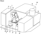
- Fig. 3 is a perspective view for illustrating the inside of Fourier transform infrared spectrophotometer 100 according to the embodiment.
- Fig. 4 is a perspective view at another angle for illustrating the inside of the Fourier transform infrared spectrophotometer according to the embodiment.
- interferometer 10 and light source unit 20 need to generate infrared interference light, and are therefore required to have high positional accuracy.
- an infrared light source and an interferometer are arranged on a two-dimensional plane of a base plate.
- infrared light source 21 and interferometer 10 are arranged on L-shaped base plate 2, instead of the two-dimensional plane of the base plate.
- L-shaped base plate 2 includes a first portion 2a provided horizontally with respect to an installation surface on which Fourier transform infrared spectrophotometer 100 is installed, and a second portion 2b provided vertically with respect to the installation surface.
- First portion 2a is provided horizontally with respect to the installation surface of Fourier transform infrared spectrophotometer 100, and its surface facing the installation surface is the lower surface and its surface opposite to the installation surface is the upper surface.
- Infrared light source 21 is disposed on the upper surface of first portion 2a. Specifically, as shown in Fig. 3 , infrared light source 21 is disposed on the upper surface of first portion 2a with a holding block 25 interposed between the infrared light source and the upper surface.
- light source unit 20 such as condenser mirror 22, collimator mirror 23, and laser light source 24 is disposed, in addition to infrared light source 21.
- Second portion 2b is provided perpendicularly with respect to the installation surface of Fourier transform infrared spectrophotometer 100, and its surface abutting against first portion 2a is the inner surface and its surface opposite to the inner surface is the outer surface.
- Interferometer 10 is disposed on the outer surface of second portion 2b.
- infrared light emitted from infrared light source 21 is reflected by condenser mirror 22 located below infrared light source 21, and is introduced into interferometer 10 by collimator mirror 23 located above condenser mirror 22.
- a window 4 is provided in second portion 2b for allowing light from collimator mirror 23 to be introduced into interferometer 10.
- condenser mirror 22 and collimator mirror 23 are fixed to the inner surface of second portion 2b.
- Infrared light source 21 disposed on the upper surface of first portion 2a is thus located on the inner surface side of second portion 2b. Therefore, interferometer 10 disposed on the outer surface of second portion 2b is located on the opposite side to infrared light source 21 with respect to second portion 2b, and heat emitted from infrared light source 21 is never transferred directly to interferometer 10, except that necessary light is introduced into interferometer 10 from window 4.
- interferometer 10 is covered with a cover member 5 made from a resin material, for example, in order to ensure airtightness, and therefore, a heat dissipation structure is difficult to employ for the interferometer.
- Cover member 5 can be made from a resin material to reduce the weight of Fourier transform infrared spectrophotometer 100. Cover member 5 is not limited to the resin material but may be a metal material.
- base plate 2 is L-shaped, heat emitted from infrared light source 21 can be blocked by second portion 2b. That is, the section where interferometer 10 is located for which a heat dissipation structure is difficult to employ and the section where light source unit 20 is located for which a heat dissipation structure is easily employed can be separated from each other by second portion 2b.
- base plate 2 can be shaped in such a manner that provides the three-dimensional arrangement in which heat emitted from infrared light source 21 is not directly transferred to interferometer 10 while a high positional accuracy is ensured. Further, as compared with the case where infrared light source 21 and interferometer 10 are arranged on a two-dimensional plane, the degree of freedom of the arrangement of infrared light source 21 and interferometer 10 is increased, which can also contribute to further compactness of Fourier transform infrared spectrophotometer 100.
- the shape of base plate 2 is described above as an L-shape that forms an angle of approximately 90° between first portion 2a and second portion 2b.
- the shape of base plate 2 is not limited to the L shape, and may be any shape as long as first portion 2a and second portion 2b form a predetermined angle.
- the predetermined angle may be any angle other than an angle (180° for example) at which first portion 2a and second portion 2b are horizontal.
- base plate 2 has a one-piece structure into which first portion 2a and second portion 2b are integrated.
- the one-piece structure of base plate 2 provides higher relative positional accuracy of infrared light source 21 and interferometer 10 arranged on base plate 2.
- first portion 2a and second portion 2b may respectively be separate structures.
- a material having a higher thermal conductivity may be used for first portion 2a where infrared light source 21 is disposed, than the thermal conductivity of a material used for second portion 2b, so that heat from infrared light source 21 is easily dissipated from first portion 2a.
- FIG. 5 is a perspective view for illustrating the light source unit of Fourier transform infrared spectrophotometer 100 according to the embodiment.
- Fig. 6 is a cross-sectional view for illustrating the light source unit of Fourier transform infrared spectrophotometer 100 according to the embodiment. As shown in Fig. 5 , infrared light source 21 is fixed to the upper surface of first portion 2a by holding block 25.
- infrared light source 21 irradiates condenser mirror 22 with infrared light
- infrared light source 21 is disposed on first portion 2a at an angle at which the optical axis from infrared light source 21 and the upper surface of first portion 2a form an oblique angle.
- infrared light source 21 includes a light emitting portion 21a that emits infrared light, and a cover 21b that covers light emitting portion 21a.
- Cover 21b is provided with a slit 21c that allows infrared light to be applied to condenser mirror 22.
- Light other than the infrared light emitted from slit 21c is trapped inside infrared light source 21 by cover 21b. Accordingly, heat is generated in infrared light source 21, resulting in increase of the temperature of infrared light source 21 itself, particularly the temperature of cover 21b.
- portions of holding block 25 that abut against infrared light source 21 are provided with a heat insulating member 25a.
- infrared light source 21 is disposed on the upper surface of first portion 2a with heat insulating member 25a interposed between the infrared light source and the upper surface. Accordingly, heat generated from infrared light source 21 is prevented from being transferred to base plate 2 through holding block 25.
- first portion 2a is constituted of a first region and a second region that border each other at the position where infrared light source 21 is located, where the first region is located on a side of second portion 2b and the second region is located on the opposite side to second portion 2b, and the area of the second region is larger than the area of the first region. Accordingly, first portion 2a includes the larger region located on the opposite side to second portion 2b where interferometer 10 is disposed, so that heat dissipation from this region can be promoted.
- FIG. 7 is a bottom view for illustrating heat dissipation from Fourier transform infrared spectrophotometer 100 according to the embodiment. As shown in Fig. 7 , the bottom surface of housing 1 is provided with a plurality of air windows 3, and heat from infrared light source 21 can be dissipated efficiently from the lower surface of first portion 2a.
- a Fourier transform infrared spectrophotometer includes: an infrared light source that emits infrared light; an interferometer that includes a beam splitter, a fixed mirror, and a moving mirror, and generates interference light from the infrared light; and a base plate including a first portion where the infrared light source is located and a second portion where the interferometer is located, wherein the base plate has a shape forming a predetermined angle between the first portion and the second portion.
- the Fourier transform infrared spectrophotometer of the present disclosure is configured to enable hindrance, to a greater extent, of heat transfer from the infrared light source to the interferometer.
- the base plate is shaped to form a predetermined angle between the first portion and the second portion, to enable three-dimensional arrangement of the infrared light source and the interferometer, which provides a higher degree of freedom of the arrangement of the infrared light source and the interferometer, and can therefore contribute to further compactness of the Fourier transform infrared spectrometer.
- the interferometer can be disposed on the second portion vertically, so that the Fourier transform infrared spectrophotometer can be made further compact, while blocking heat from the infrared light source by means of the second portion of the base plate.
- the positional accuracy of the infrared light source and the interferometer can be enhanced, and the necessary infrared interference light can be generated by the infrared light source and the interferometer.
- heat generated from the infrared light source can be trapped within the infrared light source, so that heat leaked to the first portion of the base plate can be reduced.
- heat dissipation from the second region having a larger area can be promoted to reduce a temperature change of the interferometer.
- the light from the infrared light source is reflected from the condenser mirror so that the light can be introduced efficiently into the interferometer by the collimator mirror located above the condenser mirror.
- the Fourier transform infrared spectrophotometer according to any one of Clauses 1 to 6 further includes a cover member covering the interferometer.
- the air tightness for the interferometer can be ensured, and the humidity in the cover member can be controlled to protect deliquescent optical components such as beam splitter.
- the cover member can be made from the resin material to reduce the weight of the Fourier transform infrared spectrophotometer.
Landscapes
- Physics & Mathematics (AREA)
- Spectroscopy & Molecular Physics (AREA)
- General Physics & Mathematics (AREA)
- Health & Medical Sciences (AREA)
- Life Sciences & Earth Sciences (AREA)
- Chemical & Material Sciences (AREA)
- Analytical Chemistry (AREA)
- Biochemistry (AREA)
- General Health & Medical Sciences (AREA)
- Immunology (AREA)
- Pathology (AREA)
- Spectrometry And Color Measurement (AREA)
Abstract
Description
- The present disclosure relates to a Fourier transform infrared spectrophotometer.
- Conventionally, in a Fourier transform infrared spectrophotometer (FT-IR), an infrared light source and an interferometer are arranged on a two-dimensional plane of a base plate, as shown in Japanese Utility Model Registration No. 3113903 (PTL 1). The Fourier transform infrared spectrophotometer introduces infrared light emitted from the infrared light source disposed on the base plate into the interferometer to analyze a sample placed in a sample chamber.
- PTL 1: Japanese Utility Model Registration No. 3113903
- The infrared light source emits heat while emitting infrared light, and the heat transferred to the interferometer may cause thermal expansion of optical elements such as beam splitter constituting the interferometer as well as thermal expansion of its holder, and thereby cause change of the optical axis, resulting in deterioration of the measurement accuracy. To address this, the Fourier transform infrared spectrophotometer is required to take measures against heat transfer, by providing a heater cover to prevent heat from the infrared light source from being transferred to the interferometer, and/or using a high-thermal-conductivity material for the base on which the infrared light source and the interferometer are arranged, so that heat is transferred away from the interferometer.
- An object of the present disclosure is to provide a Fourier transform infrared spectrophotometer configured to hinder, to a greater extent, heat transfer from an infrared light source to an interferometer.
- A Fourier transform infrared spectrophotometer of the present disclosure includes: an infrared light source that emits infrared light; an interferometer that includes a beam splitter, a fixed mirror, and a moving mirror, and generates interference light from the infrared light; and a base plate including a first portion where the infrared light source is located and a second portion where the interferometer is located, and the base plate has a shape forming a predetermined angle between the first portion and the second portion.
- The Fourier transform infrared spectrophotometer of the present disclosure is configured to enable hindrance, to a greater extent, of heat transfer from the infrared light source to the interferometer.
-
-
Fig. 1 is a schematic diagram of a Fourier transform infrared spectrophotometer according to an embodiment. -
Fig. 2 is a block diagram of the Fourier transform infrared spectrophotometer according to the embodiment. -
Fig. 3 is a perspective view for illustrating the inside of the Fourier transform infrared spectrophotometer according to the embodiment. -
Fig. 4 is a perspective view at another angle for illustrating the inside of the Fourier transform infrared spectrophotometer according to the embodiment. -
Fig. 5 is a perspective view for illustrating a light source unit of the Fourier transform infrared spectrophotometer according to the embodiment. -
Fig. 6 is a cross-sectional view for illustrating the light source unit of the Fourier transform infrared spectrophotometer according to the embodiment. -
Fig. 7 is a bottom view for illustrating heat dissipation from the Fourier transform infrared spectrophotometer according to the embodiment. - In the following, an embodiment of the present disclosure is described. The same parts are denoted by the same reference characters, and a description thereof is not herein repeated.
- Referring to
Figs. 1 and2 , a Fourier transforminfrared spectrophotometer 100 according to an embodiment is described.Fig. 1 is a schematic diagram of Fourier transforminfrared spectrophotometer 100 according to an embodiment.Fig. 2 is a block diagram of Fourier transforminfrared spectrophotometer 100 according to the embodiment. Fourier transforminfrared spectrophotometer 100 includes aninterferometer 10, alight source unit 20, acircuit unit 30, asample chamber 40, and adetection unit 50.Fig. 1 shows a plan view of Fourier transforminfrared spectrophotometer 100 as seen from above, and illustrates an arrangement, in ahousing 1, ofinterferometer 10,light source unit 20,circuit unit 30,sample chamber 40, anddetection unit 50. - The upper side of
Fig. 1 is the front side of Fourier transforminfrared spectrophotometer 100, and the lower side ofFig. 1 is the rear side of Fourier transforminfrared spectrophotometer 100.Interferometer 10,light source unit 20, andcircuit unit 30 are arranged on the rear side of Fourier transforminfrared spectrophotometer 100, andinterferometer 10,light source unit 20, andcircuit unit 30 are arranged side by side in this order from the left side ofFig. 1 .Interferometer 10 is attached to one portion of abase plate 2 in an L shape, which is described later herein, andlight source unit 20 is attached to another portion ofbase plate 2. -
Sample chamber 40 anddetection unit 50 are arranged on the front side of Fourier transforminfrared spectrophotometer 100, andsample chamber 40 anddetection unit 50 are arranged side by side in this order from the left side ofFig. 1 .Sample chamber 40 is covered with a lid member, and the lid member is opened to set, insample chamber 40, a sample to be measured. - With reference to
Fig. 2 , a specific configuration of Fourier transforminfrared spectrophotometer 100 is described.Interferometer 10 includes abeam splitter 11, afixed mirror 12, and a movingmirror 13, for example, andlight source unit 20 includes aninfrared light source 21, acondenser mirror 22, and acollimator mirror 23, for example.Interferometer 10 andlight source unit 20 generate infrared interference light for performing spectrum measurement. Specifically, infrared light emitted frominfrared light source 21 is transmitted tobeam splitter 11 viacondenser mirror 22 andcollimator mirror 23, and split in two directions, i.e., the direction towardfixed mirror 12 and the direction towardmoving mirror 13. - The light reflected from
fixed mirror 12 and the light reflected from movingmirror 13 are recombined bybeam splitter 11 and transmitted through an optical path directed toward aparabolic mirror 42. Movingmirror 13 reciprocates back and forth (in the directions of the arrowheads inFig. 2 ), and therefore, the light generated by the recombination is transformed into interference light (interferogram) with its amplitude varying with time. The light collected byparabolic mirror 42 is transmitted intosample chamber 40, and the light passing through asample 41 placed insample chamber 40 entersdetection unit 50. The light having entereddetection unit 50 is focused on aphotodetector 52 by anellipsoidal mirror 51. - Fourier transform
infrared spectrophotometer 100 includes a main interferometer for obtaining an interferogram and a control interferometer for controlling the sliding speed of movingmirror 13 and/or generating a timing signal for sampling a signal obtained from a detector of the main interferometer. The control interferometer is constituted of alaser light source 24, amirror 14,beam splitter 11,fixed mirror 12, and movingmirror 13, for example, and generates laser interference light for obtaining an interference pattern signal. Specifically, light emitted fromlaser light source 24 is transmitted tobeam splitter 11 viamirror 14, transformed into interference light, like the aforementioned infrared light, and transmitted towardparabolic mirror 42. Since the laser interference light travels as a light flux having a very small diameter, the laser interference light is reflected by amirror 15 inserted in the optical path and then introduced into aphotodetector 16. - Optical
components including interferometer 10 serving as a main component are disposed in an airtight chamber in which the humidity is controlled. This is mainly for protecting optical components such asbeam splitter 11 in which deliquescent KBr is used as a substrate. - The received light signal of
photodetector 16, that is, the laser light interference pattern signal is input to asignal generator 32 where a pulse signal for sampling the received light signal with respect to the infrared interference light is generated. The received light signal obtained byphotodetector 52 is amplified by anamplifier 33, sampled by a sample-and-hold circuit (S/H) 34 at a timing determined by the pulse signal, and then converted into digital data by an A/D converter (A/D) 35. Adata processor 36 performs Fourier transform on this data to generate an absorption spectrum, and further generates a transmittance spectrum using background data. A series of measurement operations is executed under control by acontroller 31.Controller 31,signal generator 32,amplifier 33, sample-and-hold circuit (S/H) 34, A/D converter (A/D) 35, anddata processor 36 are included incircuit unit 30. -
Infrared light source 21 emits heat while emitting infrared light, and the heat transferred tointerferometer 10 may cause change of an optical axis passing throughbeam splitter 11 and other opticalelements constituting interferometer 10, to thereby deteriorate the measurement accuracy. Therefore, in Fourier transforminfrared spectrophotometer 100,interferometer 10 andinfrared light source 21 are arranged in such a manner that hinders heat transfer frominfrared light source 21 tointerferometer 10. In the following, the arrangement ofinterferometer 10 andinfrared light source 21 is described with reference to the drawings. -
Fig. 3 is a perspective view for illustrating the inside of Fourier transforminfrared spectrophotometer 100 according to the embodiment.Fig. 4 is a perspective view at another angle for illustrating the inside of the Fourier transform infrared spectrophotometer according to the embodiment. As described above,interferometer 10 andlight source unit 20 need to generate infrared interference light, and are therefore required to have high positional accuracy. As such, in the conventional Fourier transform infrared spectrophotometer, an infrared light source and an interferometer are arranged on a two-dimensional plane of a base plate. - In contrast, in Fourier transform
infrared spectrophotometer 100 according to the present embodiment,infrared light source 21 andinterferometer 10 are arranged on L-shaped base plate 2, instead of the two-dimensional plane of the base plate. L-shaped base plate 2 includes afirst portion 2a provided horizontally with respect to an installation surface on which Fourier transforminfrared spectrophotometer 100 is installed, and asecond portion 2b provided vertically with respect to the installation surface. -
First portion 2a is provided horizontally with respect to the installation surface of Fourier transforminfrared spectrophotometer 100, and its surface facing the installation surface is the lower surface and its surface opposite to the installation surface is the upper surface. Infraredlight source 21 is disposed on the upper surface offirst portion 2a. Specifically, as shown inFig. 3 , infraredlight source 21 is disposed on the upper surface offirst portion 2a with a holdingblock 25 interposed between the infrared light source and the upper surface. In the space on the upper surface offirst portion 2a,light source unit 20 such ascondenser mirror 22,collimator mirror 23, andlaser light source 24 is disposed, in addition to infraredlight source 21. -
Second portion 2b is provided perpendicularly with respect to the installation surface of Fourier transforminfrared spectrophotometer 100, and its surface abutting againstfirst portion 2a is the inner surface and its surface opposite to the inner surface is the outer surface.Interferometer 10 is disposed on the outer surface ofsecond portion 2b. - Therefore, infrared light emitted from infrared
light source 21 is reflected bycondenser mirror 22 located below infraredlight source 21, and is introduced intointerferometer 10 bycollimator mirror 23 located abovecondenser mirror 22. Awindow 4 is provided insecond portion 2b for allowing light fromcollimator mirror 23 to be introduced intointerferometer 10. As shown inFig. 3 ,condenser mirror 22 andcollimator mirror 23 are fixed to the inner surface ofsecond portion 2b. - Infrared
light source 21 disposed on the upper surface offirst portion 2a is thus located on the inner surface side ofsecond portion 2b. Therefore,interferometer 10 disposed on the outer surface ofsecond portion 2b is located on the opposite side to infraredlight source 21 with respect tosecond portion 2b, and heat emitted from infraredlight source 21 is never transferred directly tointerferometer 10, except that necessary light is introduced intointerferometer 10 fromwindow 4. In particular, as shown inFig. 4 ,interferometer 10 is covered with a cover member 5 made from a resin material, for example, in order to ensure airtightness, and therefore, a heat dissipation structure is difficult to employ for the interferometer. Cover member 5 can be made from a resin material to reduce the weight of Fourier transforminfrared spectrophotometer 100. Cover member 5 is not limited to the resin material but may be a metal material. - Since
base plate 2 is L-shaped, heat emitted from infraredlight source 21 can be blocked bysecond portion 2b. That is, the section whereinterferometer 10 is located for which a heat dissipation structure is difficult to employ and the section wherelight source unit 20 is located for which a heat dissipation structure is easily employed can be separated from each other bysecond portion 2b. - Thus,
base plate 2 can be shaped in such a manner that provides the three-dimensional arrangement in which heat emitted from infraredlight source 21 is not directly transferred tointerferometer 10 while a high positional accuracy is ensured. Further, as compared with the case where infraredlight source 21 andinterferometer 10 are arranged on a two-dimensional plane, the degree of freedom of the arrangement of infraredlight source 21 andinterferometer 10 is increased, which can also contribute to further compactness of Fourier transforminfrared spectrophotometer 100. - The shape of
base plate 2 is described above as an L-shape that forms an angle of approximately 90° betweenfirst portion 2a andsecond portion 2b. However, the shape ofbase plate 2 is not limited to the L shape, and may be any shape as long asfirst portion 2a andsecond portion 2b form a predetermined angle. The predetermined angle may be any angle other than an angle (180° for example) at whichfirst portion 2a andsecond portion 2b are horizontal. - Preferably,
base plate 2 has a one-piece structure into whichfirst portion 2a andsecond portion 2b are integrated. The one-piece structure ofbase plate 2 provides higher relative positional accuracy of infraredlight source 21 andinterferometer 10 arranged onbase plate 2. As long as the relative positional accuracy of infraredlight source 21 andinterferometer 10 that are necessary for the measurement can be ensured,first portion 2a andsecond portion 2b may respectively be separate structures. Further, a material having a higher thermal conductivity may be used forfirst portion 2a where infraredlight source 21 is disposed, than the thermal conductivity of a material used forsecond portion 2b, so that heat from infraredlight source 21 is easily dissipated fromfirst portion 2a. - The heat emitted from infrared
light source 21 is described in more detail.Fig. 5 is a perspective view for illustrating the light source unit of Fourier transforminfrared spectrophotometer 100 according to the embodiment.Fig. 6 is a cross-sectional view for illustrating the light source unit of Fourier transforminfrared spectrophotometer 100 according to the embodiment. As shown inFig. 5 , infraredlight source 21 is fixed to the upper surface offirst portion 2a by holdingblock 25. Specifically, since infraredlight source 21 irradiatescondenser mirror 22 with infrared light, infraredlight source 21 is disposed onfirst portion 2a at an angle at which the optical axis from infraredlight source 21 and the upper surface offirst portion 2a form an oblique angle. - Further, as shown in
Fig. 6 , infraredlight source 21 includes alight emitting portion 21a that emits infrared light, and acover 21b that coverslight emitting portion 21a.Cover 21b is provided with aslit 21c that allows infrared light to be applied tocondenser mirror 22. Light other than the infrared light emitted fromslit 21c is trapped inside infraredlight source 21 bycover 21b. Accordingly, heat is generated in infraredlight source 21, resulting in increase of the temperature of infraredlight source 21 itself, particularly the temperature ofcover 21b. - In order to prevent heat generated from infrared
light source 21 from being transferred to holdingblock 25, portions of holdingblock 25 that abut against infraredlight source 21 are provided with aheat insulating member 25a. Specifically, infraredlight source 21 is disposed on the upper surface offirst portion 2a withheat insulating member 25a interposed between the infrared light source and the upper surface. Accordingly, heat generated from infraredlight source 21 is prevented from being transferred tobase plate 2 through holdingblock 25. - Even when holding
block 25 is provided withheat insulating member 25a, a part of heat generated from infraredlight source 21 is still transferred tobase plate 2. Therefore, heat dissipation fromfirst portion 2a is promoted, so that the heat transferred tofirst portion 2a ofbase plate 2 is not transferred tosecond portion 2b whereinterferometer 10 is located. Specifically, the upper surface offirst portion 2a is constituted of a first region and a second region that border each other at the position where infraredlight source 21 is located, where the first region is located on a side ofsecond portion 2b and the second region is located on the opposite side tosecond portion 2b, and the area of the second region is larger than the area of the first region. Accordingly,first portion 2a includes the larger region located on the opposite side tosecond portion 2b whereinterferometer 10 is disposed, so that heat dissipation from this region can be promoted. -
Housing 1 located belowfirst portion 2a is provided with anair window 3 so that heat from infraredlight source 21 transferred tofirst portion 2a can be dissipated from the lower surface offirst portion 2a to the outside ofhousing 1.Fig. 7 is a bottom view for illustrating heat dissipation from Fourier transforminfrared spectrophotometer 100 according to the embodiment. As shown inFig. 7 , the bottom surface ofhousing 1 is provided with a plurality ofair windows 3, and heat from infraredlight source 21 can be dissipated efficiently from the lower surface offirst portion 2a. - The illustrative embodiment described above will be understood by those skilled in the art as a specific example of the following aspects.
- (Clause 1) A Fourier transform infrared spectrophotometer according to one aspect includes: an infrared light source that emits infrared light; an interferometer that includes a beam splitter, a fixed mirror, and a moving mirror, and generates interference light from the infrared light; and a base plate including a first portion where the infrared light source is located and a second portion where the interferometer is located, wherein the base plate has a shape forming a predetermined angle between the first portion and the second portion.
- Thus, the Fourier transform infrared spectrophotometer of the present disclosure is configured to enable hindrance, to a greater extent, of heat transfer from the infrared light source to the interferometer. Moreover, the base plate is shaped to form a predetermined angle between the first portion and the second portion, to enable three-dimensional arrangement of the infrared light source and the interferometer, which provides a higher degree of freedom of the arrangement of the infrared light source and the interferometer, and can therefore contribute to further compactness of the Fourier transform infrared spectrometer.
- (Clause 2) The Fourier transform infrared spectrophotometer according to
Clause 1, wherein the first portion and the second portion of the base plate form an L shape. - Thus, the interferometer can be disposed on the second portion vertically, so that the Fourier transform infrared spectrophotometer can be made further compact, while blocking heat from the infrared light source by means of the second portion of the base plate.
- (Clause 3) The Fourier transform infrared spectrophotometer according to
Clause - Thus, the positional accuracy of the infrared light source and the interferometer can be enhanced, and the necessary infrared interference light can be generated by the infrared light source and the interferometer.
- (Clause 4) The Fourier transform infrared spectrophotometer according to any one of
Clauses 1 to 3, wherein the infrared light source is located on the first portion with a heat insulating member interposed between the infrared light source and the first portion. - Thus, heat generated from the infrared light source can be trapped within the infrared light source, so that heat leaked to the first portion of the base plate can be reduced.
- (Clause 5) The Fourier transform infrared spectrophotometer according to any one of
Clauses 1 to 4, wherein the first portion of the base plate is constituted of a first region and a second region that border each other at a position where the infrared light source is located, the first region being located on a side of the second portion, and the second region being located on an opposite side to the second portion, and the second region has a larger area than an area of the first region. - Thus, for the heat from the infrared light source transferred to the first portion of the base plate, heat dissipation from the second region having a larger area can be promoted to reduce a temperature change of the interferometer.
- (Clause 6) The Fourier transform infrared spectrophotometer according to any one of
Clauses 1 to 5, wherein the base plate holds the infrared light source at an oblique angle formed between an optical axis from the infrared light source and an upper surface of the first portion of the base plate. - Thus, the light from the infrared light source is reflected from the condenser mirror so that the light can be introduced efficiently into the interferometer by the collimator mirror located above the condenser mirror.
- (Clause 7) The Fourier transform infrared spectrophotometer according to any one of
Clauses 1 to 6 further includes a cover member covering the interferometer. - Thus, the air tightness for the interferometer can be ensured, and the humidity in the cover member can be controlled to protect deliquescent optical components such as beam splitter.
- (Clause 8) The Fourier transform infrared spectrophotometer according to Clause 7 allows the cover member to be made from a resin material.
- Thus, the cover member can be made from the resin material to reduce the weight of the Fourier transform infrared spectrophotometer.
- It should be construed that the embodiment and its modifications disclosed herein are given by way of illustration in all respects, not by way of limitation. It is intended that the scope of the present invention is defined by claims, not by the description above, and encompasses all variations equivalent in meaning and scope to the claims.
- 1 housing; 2 base plate; 2a first portion; 2b second portion; 3 air window; 4 window; 5 cover member; 10 interferometer; 11 beam splitter; 12 fixed mirror; 13 moving mirror; 14, 15 mirror; 16, 52 photodetector; 20 light source unit; 21 infrared light source; 21a light emitting portion; 21b cover; 21c slit; 22 condenser mirror; 23 collimator mirror; 24 laser light source; 25 holding block; 25a heat insulating member; 30 circuit unit; 31 controller; 32 signal generator; 33 amplifier; 36 data processor; 40 sample chamber; 41 sample; 42 parabolic mirror; 50 detection unit; 51 ellipsoidal mirror; 100 Fourier transform infrared spectrophotometer
Claims (8)
- A Fourier transform infrared spectrophotometer comprising:an infrared light source that emits infrared light;an interferometer that includes a beam splitter, a fixed mirror, and a moving mirror, and generates interference light from the infrared light; anda base plate including a first portion where the infrared light source is located and a second portion where the interferometer is located, whereinthe base plate has a shape forming a predetermined angle between the first portion and the second portion.
- The Fourier transform infrared spectrophotometer according to claim 1, wherein the first portion and the second portion of the base plate form an L shape.
- The Fourier transform infrared spectrophotometer according to claim 1 or 2, wherein the base plate has a one-piece structure into which the first portion and the second portion are integrated.
- The Fourier transform infrared spectrophotometer according to any one of claims 1 to 3, wherein the infrared light source is located on the first portion with a heat insulating member interposed between the infrared light source and the first portion.
- The Fourier transform infrared spectrophotometer according to any one of claims 1 to 4, whereinthe first portion of the base plate is constituted of a first region and a second region that border each other at a position where the infrared light source is located, the first region being located on a side of the second portion, and the second region being located on an opposite side to the second portion, andthe second region has a larger area than an area of the first region.
- The Fourier transform infrared spectrophotometer according to any one of claims 1 to 5, wherein the base plate holds the infrared light source at an oblique angle formed between an optical axis from the infrared light source and an upper surface of the first portion of the base plate.
- The Fourier transform infrared spectrophotometer according to any one of claims 1 to 6, further comprising a cover member covering the interferometer.
- The Fourier transform infrared spectrophotometer according to claim 7, wherein the cover member is made from a resin material.
Applications Claiming Priority (2)
| Application Number | Priority Date | Filing Date | Title |
|---|---|---|---|
| JP2021149092 | 2021-09-14 | ||
| PCT/JP2022/013506 WO2023042454A1 (en) | 2021-09-14 | 2022-03-23 | Fourier transform infrared spectrophotometer |
Publications (2)
| Publication Number | Publication Date |
|---|---|
| EP4403890A1 true EP4403890A1 (en) | 2024-07-24 |
| EP4403890A4 EP4403890A4 (en) | 2025-08-27 |
Family
ID=85601976
Family Applications (1)
| Application Number | Title | Priority Date | Filing Date |
|---|---|---|---|
| EP22869606.8A Pending EP4403890A4 (en) | 2021-09-14 | 2022-03-23 | INFRARED SPECTROMETER WITH FOURIER TRANSFORM |
Country Status (5)
| Country | Link |
|---|---|
| US (1) | US20240385105A1 (en) |
| EP (1) | EP4403890A4 (en) |
| JP (1) | JP7729390B2 (en) |
| CN (1) | CN118159811A (en) |
| WO (1) | WO2023042454A1 (en) |
Families Citing this family (1)
| Publication number | Priority date | Publication date | Assignee | Title |
|---|---|---|---|---|
| USD1115568S1 (en) * | 2021-09-13 | 2026-03-03 | Byk Gardner Gmbh | Spectral photometer |
Family Cites Families (18)
| Publication number | Priority date | Publication date | Assignee | Title |
|---|---|---|---|---|
| JPH083448B2 (en) * | 1988-10-08 | 1996-01-17 | 日本分光株式会社 | Movable mirror unit for Michelson interferometer and integrated micro Fourier infrared spectrophotometer using the same |
| US5153675A (en) * | 1990-02-22 | 1992-10-06 | Nicolet Instrument Corporation | Modular optical system for Fourier transform infrared spectrometer |
| US5406090A (en) * | 1993-02-22 | 1995-04-11 | Mattson Instruments, Inc. | Spectrometer and IR source therefor |
| JP3761992B2 (en) * | 1996-09-10 | 2006-03-29 | 日本分光株式会社 | Infrared light source device |
| JPH10206125A (en) * | 1997-01-27 | 1998-08-07 | Nippon Steel Corp | Oxide film thickness measuring device and measuring method |
| JPH11264764A (en) * | 1998-03-18 | 1999-09-28 | Jasco Corp | Spectrophotometer |
| JP3867551B2 (en) * | 2001-11-13 | 2007-01-10 | 株式会社島津製作所 | Infrared spectrophotometer |
| US7119904B2 (en) | 2004-01-13 | 2006-10-10 | Thermo Electron Scientific Instruments Corporation | Stabilized infrared source for infrared spectrometers |
| JP3113903U (en) | 2005-06-21 | 2005-09-22 | 株式会社島津製作所 | Infrared spectrophotometer |
| JP5545065B2 (en) * | 2010-06-24 | 2014-07-09 | 株式会社島津製作所 | Fourier transform infrared spectrophotometer |
| JP2012078279A (en) * | 2010-10-05 | 2012-04-19 | Shimadzu Corp | Interference spectrophotometer |
| WO2012073681A1 (en) * | 2010-12-03 | 2012-06-07 | コニカミノルタホールディングス株式会社 | Laser light source, interferometer and spectrometer |
| JP6113730B2 (en) * | 2011-09-08 | 2017-04-12 | サーモ エレクトロン サイエンティフィック インストルメンツ リミテッド ライアビリティ カンパニー | Emission and transmission optical spectrometers |
| JP2014126518A (en) * | 2012-12-27 | 2014-07-07 | Konica Minolta Inc | Optical device, michelson interferometer, and fourier transformation spectroscopic analyzer |
| CN203572578U (en) * | 2013-11-15 | 2014-04-30 | 四川威斯派克科技有限公司 | Portable Fourier near-infrared spectroscopy |
| CN107430033A (en) * | 2015-04-16 | 2017-12-01 | 株式会社岛津制作所 | Fourier transformation type spectrophotometer |
| CN109696245A (en) * | 2018-12-28 | 2019-04-30 | 北京北分瑞利分析仪器(集团)有限责任公司 | A kind of angle mirror type Michelson's interferometer |
| JP3224066U (en) * | 2019-09-10 | 2019-11-21 | 株式会社島津製作所 | Angle adjustment mechanism or Fourier transform infrared spectrophotometer equipped with the same |
-
2022
- 2022-03-23 EP EP22869606.8A patent/EP4403890A4/en active Pending
- 2022-03-23 JP JP2023548114A patent/JP7729390B2/en active Active
- 2022-03-23 CN CN202280071426.9A patent/CN118159811A/en active Pending
- 2022-03-23 US US18/690,789 patent/US20240385105A1/en active Pending
- 2022-03-23 WO PCT/JP2022/013506 patent/WO2023042454A1/en not_active Ceased
Also Published As
| Publication number | Publication date |
|---|---|
| US20240385105A1 (en) | 2024-11-21 |
| JP7729390B2 (en) | 2025-08-26 |
| JPWO2023042454A1 (en) | 2023-03-23 |
| CN118159811A (en) | 2024-06-07 |
| WO2023042454A1 (en) | 2023-03-23 |
| EP4403890A4 (en) | 2025-08-27 |
Similar Documents
| Publication | Publication Date | Title |
|---|---|---|
| US5973326A (en) | Gas monitors | |
| JP6380662B2 (en) | Fourier transform spectrophotometer | |
| US20100002235A1 (en) | Laser diode arrangements and method for gas detection | |
| US20090039267A1 (en) | Reflector module for a photometric gas sensor | |
| EP4403890A1 (en) | Fourier transform infrared spectrophotometer | |
| US20190310138A1 (en) | Infrared detector and radiation thermometer | |
| TW201907142A (en) | Pulsed radiation source for transmission high temperature measurement | |
| US7069768B2 (en) | Method and apparatus for eliminating and compensating thermal transients in gas analyzer | |
| US4555626A (en) | Radiation shield in light detector and/or assembly | |
| US4716293A (en) | Accessory for infrared emission spectroscopy | |
| US5406090A (en) | Spectrometer and IR source therefor | |
| US8729475B1 (en) | Absorption biased single beam NDIR gas sensor | |
| US11768154B2 (en) | Fourier transform infrared spectrophotometer | |
| US20230288253A1 (en) | Detector for Spectroscopy | |
| JP2014126518A (en) | Optical device, michelson interferometer, and fourier transformation spectroscopic analyzer | |
| EP2589942B1 (en) | Radiometer receiving device | |
| WO2016151786A1 (en) | Electron microscope | |
| JP2022147223A (en) | Optical measurement system, optical measurement method and measurement program | |
| CN223426528U (en) | Dual photodetector with reference gas chamber | |
| JP6642871B2 (en) | Radiation detector | |
| RU157021U1 (en) | FOURIER SPECTROMETER | |
| Kenda et al. | Advances in performance and miniaturization of a FT-IR spectrometer system based on a large stroke MOEMS piston mirror | |
| US12603708B2 (en) | Laser gas sensor with explosion proof enclosure | |
| TWI644179B (en) | Charged particle lithography system with sensor assembly | |
| HUP2400262A1 (en) | Improved system and method for spectrometric measurements |
Legal Events
| Date | Code | Title | Description |
|---|---|---|---|
| STAA | Information on the status of an ep patent application or granted ep patent |
Free format text: STATUS: THE INTERNATIONAL PUBLICATION HAS BEEN MADE |
|
| PUAI | Public reference made under article 153(3) epc to a published international application that has entered the european phase |
Free format text: ORIGINAL CODE: 0009012 |
|
| STAA | Information on the status of an ep patent application or granted ep patent |
Free format text: STATUS: REQUEST FOR EXAMINATION WAS MADE |
|
| 17P | Request for examination filed |
Effective date: 20240411 |
|
| AK | Designated contracting states |
Kind code of ref document: A1 Designated state(s): AL AT BE BG CH CY CZ DE DK EE ES FI FR GB GR HR HU IE IS IT LI LT LU LV MC MK MT NL NO PL PT RO RS SE SI SK SM TR |
|
| DAV | Request for validation of the european patent (deleted) | ||
| DAX | Request for extension of the european patent (deleted) | ||
| A4 | Supplementary search report drawn up and despatched |
Effective date: 20250728 |
|
| RIC1 | Information provided on ipc code assigned before grant |
Ipc: G01J 3/45 20060101AFI20250722BHEP Ipc: G01J 3/453 20060101ALI20250722BHEP Ipc: G01J 3/02 20060101ALI20250722BHEP Ipc: G01J 3/10 20060101ALI20250722BHEP |