EP4403822A1 - Vehicle lamp - Google Patents
Vehicle lamp Download PDFInfo
- Publication number
- EP4403822A1 EP4403822A1 EP22869854.4A EP22869854A EP4403822A1 EP 4403822 A1 EP4403822 A1 EP 4403822A1 EP 22869854 A EP22869854 A EP 22869854A EP 4403822 A1 EP4403822 A1 EP 4403822A1
- Authority
- EP
- European Patent Office
- Prior art keywords
- light guide
- light
- vehicle lamp
- guide portions
- emission region
- Prior art date
- Legal status (The legal status is an assumption and is not a legal conclusion. Google has not performed a legal analysis and makes no representation as to the accuracy of the status listed.)
- Pending
Links
Images







Classifications
-
- F—MECHANICAL ENGINEERING; LIGHTING; HEATING; WEAPONS; BLASTING
- F21—LIGHTING
- F21S—NON-PORTABLE LIGHTING DEVICES; SYSTEMS THEREOF; VEHICLE LIGHTING DEVICES SPECIALLY ADAPTED FOR VEHICLE EXTERIORS
- F21S43/00—Signalling devices specially adapted for vehicle exteriors, e.g. brake lamps, direction indicator lights or reversing lights
- F21S43/10—Signalling devices specially adapted for vehicle exteriors, e.g. brake lamps, direction indicator lights or reversing lights characterised by the light source
- F21S43/13—Signalling devices specially adapted for vehicle exteriors, e.g. brake lamps, direction indicator lights or reversing lights characterised by the light source characterised by the type of light source
- F21S43/14—Light emitting diodes [LED]
-
- B—PERFORMING OPERATIONS; TRANSPORTING
- B60—VEHICLES IN GENERAL
- B60Q—ARRANGEMENT OF SIGNALLING OR LIGHTING DEVICES, THE MOUNTING OR SUPPORTING THEREOF OR CIRCUITS THEREFOR, FOR VEHICLES IN GENERAL
- B60Q1/00—Arrangement of optical signalling or lighting devices, the mounting or supporting thereof or circuits therefor
- B60Q1/26—Arrangement of optical signalling or lighting devices, the mounting or supporting thereof or circuits therefor the devices being primarily intended to indicate the vehicle, or parts thereof, or to give signals, to other traffic
- B60Q1/2657—Arrangement of optical signalling or lighting devices, the mounting or supporting thereof or circuits therefor the devices being primarily intended to indicate the vehicle, or parts thereof, or to give signals, to other traffic mounted on a shaft, e.g. telescopic
-
- B—PERFORMING OPERATIONS; TRANSPORTING
- B60—VEHICLES IN GENERAL
- B60Q—ARRANGEMENT OF SIGNALLING OR LIGHTING DEVICES, THE MOUNTING OR SUPPORTING THEREOF OR CIRCUITS THEREFOR, FOR VEHICLES IN GENERAL
- B60Q1/00—Arrangement of optical signalling or lighting devices, the mounting or supporting thereof or circuits therefor
- B60Q1/26—Arrangement of optical signalling or lighting devices, the mounting or supporting thereof or circuits therefor the devices being primarily intended to indicate the vehicle, or parts thereof, or to give signals, to other traffic
- B60Q1/34—Arrangement of optical signalling or lighting devices, the mounting or supporting thereof or circuits therefor the devices being primarily intended to indicate the vehicle, or parts thereof, or to give signals, to other traffic for indicating change of drive direction
- B60Q1/38—Arrangement of optical signalling or lighting devices, the mounting or supporting thereof or circuits therefor the devices being primarily intended to indicate the vehicle, or parts thereof, or to give signals, to other traffic for indicating change of drive direction using immovably-mounted light sources, e.g. fixed flashing lamps
- B60Q1/381—Arrangement of optical signalling or lighting devices, the mounting or supporting thereof or circuits therefor the devices being primarily intended to indicate the vehicle, or parts thereof, or to give signals, to other traffic for indicating change of drive direction using immovably-mounted light sources, e.g. fixed flashing lamps with several light sources activated in sequence, e.g. to create a sweep effect
-
- B—PERFORMING OPERATIONS; TRANSPORTING
- B62—LAND VEHICLES FOR TRAVELLING OTHERWISE THAN ON RAILS
- B62J—CYCLE SADDLES OR SEATS; AUXILIARY DEVICES OR ACCESSORIES SPECIALLY ADAPTED TO CYCLES AND NOT OTHERWISE PROVIDED FOR, e.g. ARTICLE CARRIERS OR CYCLE PROTECTORS
- B62J6/00—Arrangement of optical signalling or lighting devices on cycles; Mounting or supporting thereof; Circuits therefor
- B62J6/05—Direction indicators
- B62J6/055—Electrical means, e.g. lamps
-
- F—MECHANICAL ENGINEERING; LIGHTING; HEATING; WEAPONS; BLASTING
- F21—LIGHTING
- F21S—NON-PORTABLE LIGHTING DEVICES; SYSTEMS THEREOF; VEHICLE LIGHTING DEVICES SPECIALLY ADAPTED FOR VEHICLE EXTERIORS
- F21S43/00—Signalling devices specially adapted for vehicle exteriors, e.g. brake lamps, direction indicator lights or reversing lights
- F21S43/20—Signalling devices specially adapted for vehicle exteriors, e.g. brake lamps, direction indicator lights or reversing lights characterised by refractors, transparent cover plates, light guides or filters
- F21S43/235—Light guides
- F21S43/236—Light guides characterised by the shape of the light guide
- F21S43/237—Light guides characterised by the shape of the light guide rod-shaped
-
- F—MECHANICAL ENGINEERING; LIGHTING; HEATING; WEAPONS; BLASTING
- F21—LIGHTING
- F21S—NON-PORTABLE LIGHTING DEVICES; SYSTEMS THEREOF; VEHICLE LIGHTING DEVICES SPECIALLY ADAPTED FOR VEHICLE EXTERIORS
- F21S43/00—Signalling devices specially adapted for vehicle exteriors, e.g. brake lamps, direction indicator lights or reversing lights
- F21S43/20—Signalling devices specially adapted for vehicle exteriors, e.g. brake lamps, direction indicator lights or reversing lights characterised by refractors, transparent cover plates, light guides or filters
- F21S43/235—Light guides
- F21S43/236—Light guides characterised by the shape of the light guide
- F21S43/241—Light guides characterised by the shape of the light guide of complex shape
-
- F—MECHANICAL ENGINEERING; LIGHTING; HEATING; WEAPONS; BLASTING
- F21—LIGHTING
- F21S—NON-PORTABLE LIGHTING DEVICES; SYSTEMS THEREOF; VEHICLE LIGHTING DEVICES SPECIALLY ADAPTED FOR VEHICLE EXTERIORS
- F21S43/00—Signalling devices specially adapted for vehicle exteriors, e.g. brake lamps, direction indicator lights or reversing lights
- F21S43/20—Signalling devices specially adapted for vehicle exteriors, e.g. brake lamps, direction indicator lights or reversing lights characterised by refractors, transparent cover plates, light guides or filters
- F21S43/235—Light guides
- F21S43/242—Light guides characterised by the emission area
- F21S43/245—Light guides characterised by the emission area emitting light from one or more of its major surfaces
-
- F—MECHANICAL ENGINEERING; LIGHTING; HEATING; WEAPONS; BLASTING
- F21—LIGHTING
- F21S—NON-PORTABLE LIGHTING DEVICES; SYSTEMS THEREOF; VEHICLE LIGHTING DEVICES SPECIALLY ADAPTED FOR VEHICLE EXTERIORS
- F21S43/00—Signalling devices specially adapted for vehicle exteriors, e.g. brake lamps, direction indicator lights or reversing lights
- F21S43/20—Signalling devices specially adapted for vehicle exteriors, e.g. brake lamps, direction indicator lights or reversing lights characterised by refractors, transparent cover plates, light guides or filters
- F21S43/235—Light guides
- F21S43/249—Light guides with two or more light sources being coupled into the light guide
- F21S43/2492—Light guides with two or more light sources being coupled into the light guide having two or more input branches
-
- F—MECHANICAL ENGINEERING; LIGHTING; HEATING; WEAPONS; BLASTING
- F21—LIGHTING
- F21S—NON-PORTABLE LIGHTING DEVICES; SYSTEMS THEREOF; VEHICLE LIGHTING DEVICES SPECIALLY ADAPTED FOR VEHICLE EXTERIORS
- F21S43/00—Signalling devices specially adapted for vehicle exteriors, e.g. brake lamps, direction indicator lights or reversing lights
- F21S43/40—Signalling devices specially adapted for vehicle exteriors, e.g. brake lamps, direction indicator lights or reversing lights characterised by the combination of reflectors and refractors
-
- B—PERFORMING OPERATIONS; TRANSPORTING
- B60—VEHICLES IN GENERAL
- B60Q—ARRANGEMENT OF SIGNALLING OR LIGHTING DEVICES, THE MOUNTING OR SUPPORTING THEREOF OR CIRCUITS THEREFOR, FOR VEHICLES IN GENERAL
- B60Q2400/00—Special features or arrangements of exterior signal lamps for vehicles
- B60Q2400/20—Multi-color single source or LED matrix, e.g. yellow blinker and red brake lamp generated by single lamp
-
- F—MECHANICAL ENGINEERING; LIGHTING; HEATING; WEAPONS; BLASTING
- F21—LIGHTING
- F21K—NON-ELECTRIC LIGHT SOURCES USING LUMINESCENCE; LIGHT SOURCES USING ELECTROCHEMILUMINESCENCE; LIGHT SOURCES USING CHARGES OF COMBUSTIBLE MATERIAL; LIGHT SOURCES USING SEMICONDUCTOR DEVICES AS LIGHT-GENERATING ELEMENTS; LIGHT SOURCES NOT OTHERWISE PROVIDED FOR
- F21K9/00—Light sources using semiconductor devices as light-generating elements, e.g. using light-emitting diodes [LED] or lasers
-
- F—MECHANICAL ENGINEERING; LIGHTING; HEATING; WEAPONS; BLASTING
- F21—LIGHTING
- F21W—INDEXING SCHEME ASSOCIATED WITH SUBCLASSES F21K, F21L, F21S and F21V, RELATING TO USES OR APPLICATIONS OF LIGHTING DEVICES OR SYSTEMS
- F21W2103/00—Exterior vehicle lighting devices for signalling purposes
- F21W2103/20—Direction indicator lights
-
- F—MECHANICAL ENGINEERING; LIGHTING; HEATING; WEAPONS; BLASTING
- F21—LIGHTING
- F21W—INDEXING SCHEME ASSOCIATED WITH SUBCLASSES F21K, F21L, F21S and F21V, RELATING TO USES OR APPLICATIONS OF LIGHTING DEVICES OR SYSTEMS
- F21W2107/00—Use or application of lighting devices on or in particular types of vehicles
- F21W2107/10—Use or application of lighting devices on or in particular types of vehicles for land vehicles
- F21W2107/13—Use or application of lighting devices on or in particular types of vehicles for land vehicles for cycles
- F21W2107/17—Use or application of lighting devices on or in particular types of vehicles for land vehicles for cycles for motorcycles
-
- F—MECHANICAL ENGINEERING; LIGHTING; HEATING; WEAPONS; BLASTING
- F21—LIGHTING
- F21Y—INDEXING SCHEME ASSOCIATED WITH SUBCLASSES F21K, F21L, F21S and F21V, RELATING TO THE FORM OR THE KIND OF THE LIGHT SOURCES OR OF THE COLOUR OF THE LIGHT EMITTED
- F21Y2115/00—Light-generating elements of semiconductor light sources
- F21Y2115/10—Light-emitting diodes [LED]
-
- G—PHYSICS
- G02—OPTICS
- G02B—OPTICAL ELEMENTS, SYSTEMS OR APPARATUS
- G02B6/00—Light guides; Structural details of arrangements comprising light guides and other optical elements, e.g. couplings
- G02B6/0001—Light guides; Structural details of arrangements comprising light guides and other optical elements, e.g. couplings specially adapted for lighting devices or systems
Definitions
- the present invention relates to a vehicle lamp.
- Patent Document 1 discloses a vehicle lamp that is a direction indicator (turn lamp) including a plurality of light sources configured to emit light in the same direction and a light guide configured to guide the light emitted from the plurality of light sources in the same direction, and configured to perform sequential emission of directing a flow of emission in a vehicle width direction in a light emitting surface of the light guide while sequentially turning on the plurality of light sources.
- a direction indicator turn lamp
- Patent Document 1 Japanese Unexamined Patent Application, First Publication No. 2017-183287
- a light emitting surface with a sufficient length in the direction of the light flow is required.
- a sufficient number of light sources are required for sequential emission.
- An aspect of the present invention is directed to providing a vehicle lamp capable of increasing visibility by sequential emission even when a length of a light emitting surface is short and the number of light sources is small.
- the present invention provides the following configurations.
- the aspect of the present invention it is possible to provide a vehicle lamp capable of increasing visibility by sequential emission even when a length of a light emitting surface is short and the number of light sources is small.
- an XYZ orthogonal coordinate system is set, with an X-axis direction indicating a forward/rearward direction (lengthwise direction) of a vehicle lamp, a Y-axis direction indicating a leftward/rightward direction (widthwise direction) of the vehicle lamp, and a Z-axis direction indicating an upward/downward direction (height direction) of the vehicle lamp.
- a vehicle lamp 1 shown in FIG. 1 to FIG. 7 will be described.
- FIG. 1 is a perspective view showing a configuration of the vehicle lamp 1.
- FIG. 2 is a front view showing a configuration of the vehicle lamp 1.
- FIG. 3 is a plan view showing a configuration of the vehicle lamp 1.
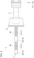
- FIG. 4 is a rear view showing a configuration of the vehicle lamp 1.
- FIG. 5 is a side view showing a configuration of the vehicle lamp 1.
- FIG. 6 is a cross-sectional view showing an optical path of light L in the vehicle lamp 1.
- FIG. 7 is a perspective view showing a configuration of a lighting body 4 provided in the vehicle lamp 1.
- the vehicle lamp 1 of the embodiment is obtained by applying the present invention to direction indicators (turn lamps) disposed laterally symmetrically on a front side or a rear side of a saddle riding vehicle such as a motorcycle, an auto tricycle, or the like (hereinafter, simply referred to as "a vehicle").
- direction indicators turn lamps
- the vehicle lamp 1 includes a plurality of (in the embodiment, two) light sources 2A and 2B configured to emit light L in the same direction, a light guide body 3 configured to guide the light L emitted from the plurality of light sources 2A and 2B, and the lighting body 4 configured to hold the plurality of light sources 2A and 2B and the light guide body 3.
- a plurality of (in the embodiment, two) light sources 2A and 2B configured to emit light L in the same direction
- a light guide body 3 configured to guide the light L emitted from the plurality of light sources 2A and 2B
- the lighting body 4 configured to hold the plurality of light sources 2A and 2B and the light guide body 3.
- the lighting body 4 constitutes a stay that is attached in a cantilevered manner in the vehicle width direction from the front side of the vehicle.
- the plurality of light sources 2A and 2B are disposed inside a housing part 4a provided on a tip side of the lighting body 4.
- the light guide body 3 has a cap part 3a configured to close the housing part 4a, and the cap part 3a is integrally attached to a periphery of the housing part 4a by welding or the like.
- the plurality of light sources 2A and 2B are constituted by light emitting diodes (LEDs) configured to emit orange light (hereinafter, simply referred to as "light") L.
- the plurality of light sources 2A and 2B are arranged in a forward/rearward direction of the vehicle while each being mounted on one surface of a circuit board 5.
- the circuit board 5 is attached to the inside of the housing part 4a by screws or the like.
- each of the light sources 2A and 2B radially emits the light L in a direction perpendicular to one surface of the circuit board 5 (vehicle width direction). That is, the plurality of light sources 2A and 2B are configured to radially emit the light L in the same direction.
- a partition wall 4b configured to partition a space between one light source (hereinafter discriminated as “a first light source” according to necessity) 2A and another light source (hereinafter discriminated as “a second light source” according to necessity) 2B, which are adjacent to each other, is provided inside the housing part 4a.
- the plurality of light sources 2A and 2B are not necessarily limited to the configuration mounted on the separate circuit boards 5 as described above, but for example, the plurality of light sources 2A and 2B may be mounted on the same surface of the same circuit board 5.
- the vehicle lamp 1 of the embodiment has a configuration in which a connector part (not shown) including a wiring electrically connected to the circuit board 5 is pulled out of a base end side of the lighting body 4 to the outside.
- the light guide body 3 has a plurality of (in the embodiment, two) light guide portions 6A and 6B extending in the same directions from positions facing the plurality of light sources 2A and 2B, respectively.
- the light guide portions 6A and 6B have elongated shapes with widths in the forward/rearward direction that gradually increase from a base end side toward a tip side.
- the plurality of light guide portions 6A and 6B are disposed while arranged parallel to each other in the forward/rearward direction of the light guide body 3 and have lengths that sequentially increase from a rear side toward a front side of the light guide body 3. That is, among the plurality of light guide portions 6A and 6B, a length of a light guide portion (hereinafter discriminated as "a second light guide portion” according to necessity) 6B in an extension direction, which is located on a front side, is greater than a length of a light guide portion (hereinafter discriminated as "a first light guide portion" according to necessity) 6A in an extension direction, which is located on a rear side.
- a length of the light guide portion (in the example, the first light guide portion 6A) in the extension direction, which is located on the rear side is smaller than the length of the light guide portion (in the example, the second light guide portion 6B) in the extension direction, which is provided at a position closer to the front side than the light guide portion (in the example, the first light guide portion 6A) which is located on the rear side.
- the light guide body 3 has the first light guide portion 6A extending from a position facing the first light source 2A.
- the light guide body 3 has the second light guide portion 6B extending from a position facing the second light source 2B.
- the first light guide portion 6A and the second light guide portion 6B extend in the same direction.
- the light guide body 3 has a structure in which a slit portion 7 is provided between the first light guide portion 6A and the second light guide portion 6B which are adjacent to each other and a tip side of the first light guide portion 6A is connected to a midway part of the second light guide portion 6B via a connecting portion 8.
- the light guide body 3 has a structure in which the connecting portion 8 connecting the tip side of the first light guide portion 6A and the midway part of the second light guide portion 6B is provided and in which the slit portion 7 is formed between the first light guide portion 6A, the second light guide portion 6B and the connecting portion 8.
- the light guide body 3 has a plurality of (in the embodiment, two) incidence parts 9 disposed on base end sides of the plurality of light guide portions 6A and 6B, respectively, and configured to cause the light L emitted from the light sources 2A and 2B to enter therein.
- the light guide body 3 has a first incidence part 9 disposed on the base end side of the first light guide portion 6A and configured to cause the light L emitted from the first light source 2A to enter therein.
- the light guide body 3 has a second incidence part 9 disposed on the base end side of the second light guide portion 6B and configured to cause the light L emitted from the second light source 2B to enter therein.
- Each of the incidence parts (the first incidence part and the second incidence part) 9 has a first focusing incident surface 9a that is disposed at a center of a portion facing each of the light sources 2A and 2B and that is configured to cause some of the light L emitted from the light sources 2A and 2B to enter therein, a second focusing incident surface 9b that is located on an inner circumferential side of a protrusion part protruding from a position surrounding the first focusing incident surface 9a toward the light sources 2A and 2B and that is configured to cause some of the light L emitted from the light sources 2A and 2B to enter therein, and a focusing reflecting surface 9c that is located on an outer circumferential side of the protrusion part and that is configured to reflect the light L entering from the second focusing incident surface 9b.
- the light L entered from the first focusing incident surface 9a among the light L emitted from the light sources 2A and 2B is focused toward the optical axis of the light L emitted from the light sources 2A and 2B.
- the light L entered from the second focusing incident surface 9b is focused toward the optical axis of the light L emitted from the light sources 2A and 2B by reflecting the light L entered from the second focusing incident surface 9b by the focusing reflecting surface 9c.
- the light L radially emitted from the light sources 2A and 2B enters the light guide portions 6A and 6B while the light L radially emitted from the light sources 2A and 2B is parallelized and focused.
- the light L entered from the incidence parts 9 is guided toward the tip sides of the light guide portions 6A and 6B.
- the light guide body 3 has a plurality of (in the embodiment, two) first reflection parts 10 that are disposed at opposite sides to the incidence parts 9 of the plurality of light guide portions 6A and 6B, respectively.
- Each of the first reflection parts 10 has an inclined surface 10a that is inclined at a predetermined angle (in the embodiment, 45° with respect to the optical axis of the light L) toward the front sides of the light guide portions 6A and 6B and that is disposed at the tip side of each of the light guide portions 6A and 6B.
- the light L entered the inclined surface 10a is reflected toward the front sides of the light guide portions 6A and 6B.
- the light L reflected by the inclined surface 10a provided on the tip side of the first light guide portion 6A enters the second light guide portion 6B from the rear side of the second light guide portion 6B via the connecting portion 8 and is guided toward the front side of the second light guide portion 6B.
- the light L reflected by the inclined surface 10a provided on the tip side of the second light guide portion 6B is guided toward the front side of the second light guide portion 6B.
- the light guide body 3 has a plurality of (in the embodiment, two) second reflection parts 11 disposed on the rear sides of the plurality of light guide portions 6A and 6B, respectively.
- Each of the second reflection parts 11 has a plurality of reflection cuts 11a arranged in a direction in which each of the light guide portions 6A and 6B extends (in the embodiment, in the vehicle width direction).
- the plurality of reflection cuts 11a may be configured to reflect the light L that has entered the rear sides of the light guide portions 6A and 6B by an angle where the light is emitted (transmitted) to the outside from the front sides of the light guide portions 6A and 6B, and the shape, the size, the number, or the like, is not particularly limited thereto.
- the reflection cuts 11a which have a substantially triangular cross section and which is obtained by cutting out the back surfaces of the light guide portions 6A and 6B in the upward/downward direction of the light guide body 3, are arranged next to each other in the extension direction of the light guide portions 6A and 6B.
- the plurality of reflection cuts 11a are provided at positions except a portion facing the slit portion 7. That is, among the back surface of the first light guide portion 6A, the plurality of reflection cuts 11a are provided across between the cap part 3a and the inclined surface 10a. In addition, among the back surface of the second light guide portion 6B, the plurality of reflection cuts 11a are provided across between the adjacent inclined surfaces 10a in a direction in which the second light guide portion 6B extends (vehicle width direction). Meanwhile, the front surface of the first light guide portion 6A and the back surface of the second light guide portion 6B, which face the slit portion 7, mutually form flat surfaces.
- the light L entering the plurality of reflection cuts 11a is reflected toward the front sides of the light guide portions 6A and 6B.
- the light L reflected by the plurality of reflection cuts 11a provided on the rear side of the first light guide portion 6A is emitted toward the outside from the front side of the first light guide portion 6A, passes through the slit portion 7, enters the second light guide portion 6B from the rear side of the second light guide portion 6B, and then, is guided to the front side of the second light guide portion 6B.
- the light L reflected by the plurality of reflection cuts 11a provided on the rear side of the second light guide portion 6B is guided toward the front side of the second light guide portion 6B.
- the light guide body 3 has a light emitting portion 12 that is disposed on the front side of the second light guide portion 6B located on the foremost side of the plurality of light guide portions 6A and 6B.
- the light emitting portion 12 includes a first emission region E1 configured to emit light by the light L reflected by the inclined surface 10a (the first reflection parts 10) to the outside, and a second emission region E2 configured to emit light by the light L reflected by the plurality of reflection cuts 11a (the second reflection parts 11) to the outside, and a light emitting surface 12a in which the first emission region E1 and the second emission region E2 are alternately aligned in the extension direction (vehicle width direction) of the second light guide portion 6B.
- the light L emitted from the light emitting surfaces 12a toward the outside causes the light emitting surfaces 12a to emit orange color.
- intensity of the light L reflected by the inclined surface 10a (the first reflection parts 10) is higher than intensity of the light reflected by the plurality of reflection cuts 11a (the second reflection parts 11). Accordingly, the first emission region E1 emits light more strongly than the second emission region E2. In addition, a width of the second emission region E2 is greater than that of the first emission region E1.
- the first emission region E1 forms "a bright section” with a small width that relatively brightly emits light.
- the second emission region E2 forms "a dark section” with a large width that relatively darkly emits light.
- the second emission region E2 as “the dark section,” the first emission region E1 as “the bright section,” the second emission region E2 as “the dark section” and the first emission region E1 as “the bright section” are alternately disposed from the base end side toward the tip side in the vehicle width direction.
- a plurality of diffusion cuts 12b configured to diffuse the light L emitted from the light emitting surfaces 12a toward the outside (a side in front of the vehicle) are provided on the light emitting portion 12.
- the diffusion cuts 12b for example, a lens cut referred to as a flute cut or a fisheye cut, a concavo-convex structure or the like formed by performing knurling, embossing, or the like, may be exemplified.
- a shape or the like of the diffusion cut a diffusion degree of the light L emitted from the light emitting surfaces 12a can be controlled.
- the fisheye cut configured to diffuse the light L emitted from the light emitting surfaces 12a in the upward/downward direction and the leftward/rightward direction of the vehicle is provided.
- sequential emission of directing a flow of emission by the first emission region E1 and the second emission region E2 in the light emitting surfaces 12a is performed while sequentially turning on the plurality of light sources 2A and 2B.
- sequential emission as direction indicators is performed by sequentially repeating turning-on and turning-off of the plurality of light sources 2A and 2B.
- the first light source 2A and the second light source 2B are in a turned-off state. At this time, the light emitting surfaces 12a are in a non-emission state.
- the first light source 2A is in a turned-on state
- the second light source 2B is in a turned-off state.
- the second emission region E2 as "the dark section” and the first emission region E1 as “the bright section” become an emission state from the base end side toward the tip side of the light emitting surfaces 12a.
- the first light source 2A and the second light source 2B are in the turned-on state.
- the second emission region E2 as "the dark section” the first emission region E1 as “the bright section”
- the second emission region E2 as “the dark section” and the first emission region E1 as “the bright section” become the emission state from the base end side toward the tip side of the light emitting surfaces 12a.
- sequential emission may be performed according to inversed procedures of the procedures (1) to (3).
- the first light source 2A may be in a turned-off state, and the second light source 2B is in a turned-on state.
- the second emission region E2 as "the dark section” and the first emission region E1 as “the bright section” becomes in the emission state while having the second emission region E2 and the first emission region E1 of "the non-emission state" being interposed between from the base end side toward the tip side of the light emitting surfaces 12a. Even in this case, it is possible to direct a flow of the emission by the first emission region E1 and the second emission region E2 in the light emitting surfaces 12a.
- the vehicle lamp 1 of the embodiment it is possible to increase visibility through sequential emission by directing a flow of emission by the first emission region E1 (bright section) and the second emission region E2 (dark section) in the light emitting surfaces 12a while sequentially turning on the above mentioned plurality of light sources 2A and 2B even when the length of the light emitting surface 12a is small and the number of the light sources 2A and 2B is small.
- FIG. 8 is a cross-sectional view showing a configuration of the vehicle lamp 1A.
- the same area as the vehicle lamp 1 will not be described, and the same reference signs in the drawings may be attached thereto.
- the vehicle lamp 1A of the embodiment includes three light sources 2A, 2B and 2C configured to emit the light L in the same direction, and a light guide body 3A including three light guide portions 6A, 6B and 6C configured to guide the light L emitted from the light sources 2A, 2B and 2C, respectively.
- the vehicle lamp 1A is configured by adding a third light source 2C adjacent to the second light source 2B and a third light guide portion 6C adjacent to the second light guide portion 6B to the configuration of the vehicle lamp 1.
- the light guide body 3A has a configuration in which the slit portion 7 is provided between the second light guide portion 6B and the third light guide portion 6C adjacent to each other, and a tip side of the second light guide portion 6B is connected to a midway part of the third light guide portion 6C via the connecting portion 8.
- the second emission region E2 as “the dark section,” the first emission region E1 as “the bright section,” the second emission region E2 as “the dark section,” the first emission region E1 as “the bright section,” the second emission region E2 as “the dark section” and the first emission region E1 as “the bright section” are arranged alternately from the base end side toward the tip side in the vehicle width direction.
- the vehicle lamp 1A of the embodiment having the above-mentioned configuration it is possible to perform sequential emission of directing a flow of emission by the first emission region E1 (bright section) and the second emission region E2 (dark section) in the light emitting surfaces 12a while sequentially turning on the plurality of the light sources 2A, 2B and 2C.
- the vehicle lamp 1A of the embodiment it is possible to increase the number of the light sources 2A, 2B and 2C and the number of the light guide portions 6A, 6B and 6C corresponding thereto, extend the length of the light emitting surfaces 12a, increase the number of the first emission region E1 (bright section) and the second emission region E2 (dark section) in the light emitting surfaces 12a, and increase visibility by sequential emission.
- a vehicle lamp 1B shown in FIG. 9 will be described.
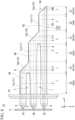
- FIG. 9 is a cross-sectional view showing a configuration of the vehicle lamp 1B.
- the same area as the vehicle lamp 1 will not be described, and the same reference signs in the drawings may be attached thereto.
- the vehicle lamp 1B of the embodiment has basically the same configuration as the vehicle lamp 1 except that the light guide body 3B configured differently from the first light guide portion 6A and the second light guide portion 6B of the vehicle lamp 1 is provided.
- each of the first light guide portion 6A and the second light guide portion 6B has the first reflection part 10 in which the plurality of (in the embodiment, two) inclined surfaces 10a are disposed, and the second reflection part 11 in which the plurality of (in the embodiment, two) reflection cuts 11a are disposed.
- stepped surfaces are provided at the rear side of the first light guide portion 6A and the second light guide portion 6B on both sides of the inclined surface 10a, and the plurality of reflection cuts 11a are arranged on each of the stepped surfaces in the extension direction of the light guide portions 6A and 6B.
- the inclined surfaces 10a are provided on the tip sides of the first light guide portion 6A and the second light guide portion 6B, respectively.
- the second emission region E2 as “the dark section,” the first emission region E1 as “the bright section,” the second emission region E2 as “the dark section,” the first emission region E1 as “the bright section,” the second emission region E2 as “the dark section,” the first emission region E1 as “the bright section,” the second emission region E2 as “the dark section” and the first emission region E1 as “the bright section” are arranged from the base end side toward the tip side in the vehicle width direction.
- the vehicle lamp 1B of the embodiment having the above-mentioned configuration it is possible to perform sequential emission of directing a flow of emission by the first emission region E1 (bright section) and the second emission region E2 (dark section) in the light emitting surfaces 12a while sequentially turning on the plurality of light sources 2A and 2B.
- the vehicle lamp 1B of the embodiment it is possible to increase visibility by sequential emission while increasing the number of the first emission region E1 and the second emission region E2 in the light emitting surfaces 12a without increasing the number of light sources 2A and 2B and the number of the light guide portions 6A and 6B corresponding thereto.
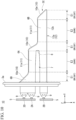
- FIG. 10 is a cross-sectional view showing a configuration of the vehicle lamp 1C.
- the same area as the vehicle lamp 1 will not be described, and the same reference signs in the drawings may be attached thereto.
- the vehicle lamp 1C of the embodiment includes three light sources 2D, 2A and 2B configured to emit the light L in the same direction, and a light guide body 3C including three light guide portions 6D, 6A and 6B configured to guide the light L emitted from the light sources 2D, 2A and 2B, respectively.
- the vehicle lamp 1A is configured by adding the third light source 2D adjacent to the first light source 2A and the third light guide portion 6D adjacent to the first light guide portion 6A to the configuration of the vehicle lamp 1.
- the light guide body 3C has a configuration in which the third light guide portion 6D and the first light guide portion 6A adjacent to each other are formed integrally, and the inclined surface 10a is provided on the tip side of the third light guide portion 6D.
- the first emission region E1 as “the bright section,” the second emission region E2 as “the dark section,” the first emission region E1 as “the bright section,” the second emission region E2 as “the dark section” and the first emission region E1 as “the bright section” are arranged alternately from the base end side toward the tip side in the vehicle width direction.
- the vehicle lamp 1C of the embodiment having the above-mentioned configuration it is possible to perform sequential emission of directing a flow of emission by the first emission region E1 (bright section) and the second emission region E2 (dark section) in the light emitting surfaces 12a while sequentially turning on the plurality of light sources 2D, 2A and 2B.
- the vehicle lamp 1C of the embodiment it is possible to increase the number of the first emission region E1 and the second emission region E2 in the light emitting surfaces 12a and increase visibility by sequential emission while increasing the number of the light sources 2D, 2A and 2B and the number of the light guide portions 6D, 6A and 6B without extending the length of the light emitting surfaces 12a.
- a vehicle lamp 1D shown in FIG. 11 will be described.
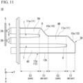
- FIG. 11 is a cross-sectional view showing a configuration of the vehicle lamp 1D.
- the same area as the vehicle lamp 1 will not be described, and the same reference signs in the drawings may be attached thereto.
- the vehicle lamp 1D of the embodiment includes a light guide body 3D including three light guide portions 6A, 6B and 6E.
- the vehicle lamp 1D is configured by adding a third light guide portion 6E adjacent to the second light guide portion 6B to the configuration of the above mentioned vehicle lamp 1.
- the light guide body 3D has a structure in which the slit portion 7 is provided between the second light guide portion 6B and the third light guide portion 6E adjacent to each other, and the tip side of the second light guide portion 6B is connected to a tip portion of the third light guide portion 6E via the connecting portion 8.
- the light guide body 3D has the light emitting portion 12 (the light emitting surfaces 12a) disposed on the front side of the third light guide portion 6E located on the foremost side of the plurality of light guide portions 6A, 6B and 6E.
- the second emission region E2 as “the dark section,” the first emission region E1 as “the bright section,” the second emission region E2 as “the dark section,” the first emission region E1 as “the bright section,” the second emission region E2 as “the dark section” and the first emission region E1 as “the bright section” are arranged alternately from the base end side toward the tip side in the vehicle width direction.
- the vehicle lamp 1D of the embodiment having the above-mentioned configuration it is possible to perform sequential emission of directing a flow of emission by the first emission region E1 (bright section) and the second emission region E2 (dark section) in the light emitting surfaces 12a while sequentially turning on the plurality of light sources 2A and 2B.
- the vehicle lamp 1D of the embodiment even when the length of the light emitting surface 12a is small and the number of the light sources 2A and 2B is small, it is possible to increase visibility by sequential emission.
- a vehicle lamp 1E shown in FIG. 12 will be described.
- FIG. 12 is a cross-sectional view showing a configuration of the vehicle lamp 1E.
- the same area as the vehicle lamp 1 will not be described, and the same reference signs in the drawings may be attached thereto.
- the vehicle lamp 1E of the embodiment includes a light guide body 3E including two light guide portions 6F and 6G.
- the light guide body 3E has a configuration including the light guide portions 6F and 6G obtained by adding inclined surfaces 13 to the light guide portions 6A and 6B, respectively.
- the light guide body 3E has a shape curved in the light guide portions 6F and 6G at a predetermined angle (in the embodiment, 90°) by the inclined surface 13.
- the inclined surface 13 is inclined at a predetermined angle (in the embodiment, 45° with respect to the optical axis of the light L) at front of the cap part 3a, and the light L guided toward the tip sides of the light guide portions 6F and 6G is reflected at the predetermined angle (in the embodiment, 90° with respect to the optical axis of the light L).
- the vehicle lamp 1E of the embodiment having the above-mentioned configuration it is possible to perform sequential emission of directing a flow of emission by the first emission region E1 (bright section) and the second emission region E2 (dark section) in the light emitting surfaces 12a while sequentially turning on the plurality of light sources 2A and 2B.
- the vehicle lamp 1E of the embodiment even when the length of the light emitting surface 12a is small and the number of the light sources 2A and 2B is small, it is possible to increase visibility by sequential emission.
- the vehicle lamp 1 may have a configuration in which each of the light sources 2A and 2B includes a plurality of (two in FIG. 13 ) emission elements 20a and 20b with different colored lights.
- each of the light sources 2A and 2B includes a plurality of (two in FIG. 13 ) emission elements 20a and 20b with different colored lights.
- an LED configured to emit orange light as a first emission element 20a and an LED configured to emit red light as a second emission element 20b are used.
- the vehicle lamp to which the present invention is applied is not limited to one mounted on the saddle riding vehicle described above, but may be mounted on a vehicle such as a four-wheeled vehicle.
- the vehicle lamp to which the present invention is applied although it is suitably used as the direction s (turn lamps) that perform the above-mentioned sequential emission, for example, the present invention can be widely applied to the vehicle lamp having light emitting surfaces such as width indicators (position lamps), daytime running lamps (DRLs), tail lights (tail lamp), brake lamps (stop lamps), back lamps, and the like.
- the light source in addition to the above-mentioned LED, for example, an emission element such as a laser diode (LD) or the like can be used.
- the color of the light L emitted by the light source is not limited to the above-mentioned orange light, but can be changed as appropriate, such as red light or white light, depending on the use of the vehicle lamp.
Landscapes
- Engineering & Computer Science (AREA)
- General Engineering & Computer Science (AREA)
- Mechanical Engineering (AREA)
- Physics & Mathematics (AREA)
- Microelectronics & Electronic Packaging (AREA)
- Optics & Photonics (AREA)
- Non-Portable Lighting Devices Or Systems Thereof (AREA)
- Planar Illumination Modules (AREA)
Abstract
Description
- The present invention relates to a vehicle lamp.
- Priority is claimed on
Japanese Patent Application No. 2021-151725, filed September 17, 2021 - In the related art, as vehicle lamps installed in vehicles, a lamp obtained by combining a light source such as a light emitting diode (LED) or the like and a light guide such as an inner lens or the like is known (for example, see the following Patent Document 1). In such a vehicle lamp, due to diversification of designs, various forms have been developed.
- For example, the following
Patent Document 1 discloses a vehicle lamp that is a direction indicator (turn lamp) including a plurality of light sources configured to emit light in the same direction and a light guide configured to guide the light emitted from the plurality of light sources in the same direction, and configured to perform sequential emission of directing a flow of emission in a vehicle width direction in a light emitting surface of the light guide while sequentially turning on the plurality of light sources. - [Patent Document 1]
Japanese Unexamined Patent Application, First Publication No. 2017-183287 - Incidentally, in the vehicle lamp that performs the above-mentioned sequential emission, in order to make it appear as if the light is flowing, a light emitting surface with a sufficient length in the direction of the light flow is required. In addition, a sufficient number of light sources are required for sequential emission.
- An aspect of the present invention is directed to providing a vehicle lamp capable of increasing visibility by sequential emission even when a length of a light emitting surface is short and the number of light sources is small.
- In order to achieve the aforementioned objects, the present invention provides the following configurations.
- (1) A vehicle lamp including:
- a plurality of light sources configured to emit light in same direction; and
- a light guide body configured to guide light emitted from the plurality of light sources,
- wherein the light guide body has:
- a plurality of light guide portions that are disposed parallel to each other while extending in same direction with each other from positions facing each of the plurality of light sources, respectively;
- a plurality of incidence parts that are disposed on base end sides of each of the plurality of light guide portions, and that are configured to cause light emitted from the light sources to enter therein;
- a plurality of first reflection parts that are disposed at sides opposite to the incidence parts of each of the plurality of light guide portions, respectively, and that are configured to reflect light guided toward the tip side of the light guide portions toward a front side of the light guide portions;
- a plurality of second reflection parts that are disposed on rear sides of each of the plurality of light guide portions, respectively, and that are configured to reflect light which has entered the rear side of the light guide portions toward the front side of the light guide portions; and
- a light emitting portion that is disposed on a front side of a light guide portion which is located on a foremost side of the plurality of light guide portions and that is configured to emit light reflected by the first reflection parts and the second reflection parts to outside, and
- lengths of the plurality of light guide portions sequentially increase from the light guide portion disposed at the rear side toward the light guide portion disposed at the front side of the light guide body and the plurality of light guide portions have a structure in which a slit portion is provided between the light guide portion disposed at the rear side and the light guide portion disposed at the front side which are adjacent to each other, and in which a tip side of the light guide portion disposed at the rear side is connected to the light guide portion disposed at the front side via a connecting portion.
- (2) The vehicle lamp according to the above-mentioned (1), wherein the light emitting portion includes a first emission region configured to emit light by light reflected by the first reflection parts, and a second emission region configured to emit light by light reflected by the second reflection parts, and
the first emission region emits light more strongly than the second emission region. - (3) The vehicle lamp according to the above-mentioned (2), wherein the light emitting portion has a light emitting surface in which the first emission region and the second emission region are arranged alternately in a vehicle width direction, and
sequential emission of directing a flow of emission by the first emission region and the second emission region in the light emitting surface is performed while sequentially turning on the plurality of light sources. - (4) The vehicle lamp according to any one of the above-mentioned (1) to (3), wherein the first reflection parts include inclined surfaces inclined toward the front side of the light guide portions, and
the second reflection parts include a plurality of reflection cuts arranged in a direction in which the light guide portions extend. - (5) The vehicle lamp according to the above-mentioned (4), wherein the plurality of reflection cuts are provided on back surfaces of the light guide portions at positions except portions facing the slit portion.
- (6) The vehicle lamp according to the above-mentioned (5), wherein the plurality of reflection cuts are provided between the inclined surfaces adjacent to each other in the direction in which the light guide portions extend.
- According to the aspect of the present invention, it is possible to provide a vehicle lamp capable of increasing visibility by sequential emission even when a length of a light emitting surface is short and the number of light sources is small.
-
-
FIG. 1 is a perspective view showing a configuration of a vehicle lamp according to a first embodiment of the present invention. -
FIG. 2 is a front view showing the configuration of the vehicle lamp shown inFIG. 1 . -
FIG. 3 is a plan view showing the configuration of the vehicle lamp shown inFIG. 1 . -
FIG. 4 is a rear view showing the configuration of the vehicle lamp shown inFIG. 1 . -
FIG. 5 is a side view showing the configuration of the vehicle lamp shown inFIG. 1 . -
FIG. 6 is a cross-sectional view showing an optical path of light in the vehicle lamp shown inFIG. 1 . -
FIG. 7 is a perspective view showing a configuration of a lighting body provided in the vehicle lamp shown inFIG. 1 . -
FIG. 8 is a cross-sectional view showing a configuration of a vehicle lamp according to a second embodiment of the present invention. -
FIG. 9 is a cross-sectional view showing a configuration of a vehicle lamp according to a third embodiment of the present invention. -
FIG. 10 is a cross-sectional view showing a configuration of a vehicle lamp according to a fourth embodiment of the present invention. -
FIG. 11 is a cross-sectional view showing a configuration of a vehicle lamp according to a fifth embodiment of the present invention. -
FIG. 12 is a cross-sectional view showing a configuration of a vehicle lamp according to a sixth embodiment of the present invention. -
FIG. 13 is a cross-sectional view showing a main part of a variant of the light source. - Hereinafter, embodiments of the present invention will be described in detail with reference to the accompanying drawings.
- Further, in the drawings used in the following description, in order to make it easier to see each component, dimensions may be shown at different scales depending on the component, and a dimension ratio of each component may not be the same as it actually is.
- In addition, in the drawings described below, an XYZ orthogonal coordinate system is set, with an X-axis direction indicating a forward/rearward direction (lengthwise direction) of a vehicle lamp, a Y-axis direction indicating a leftward/rightward direction (widthwise direction) of the vehicle lamp, and a Z-axis direction indicating an upward/downward direction (height direction) of the vehicle lamp.
- First, as a first embodiment of the present invention, for example, a
vehicle lamp 1 shown inFIG. 1 to FIG. 7 will be described. - Further,
FIG. 1 is a perspective view showing a configuration of thevehicle lamp 1.FIG. 2 is a front view showing a configuration of thevehicle lamp 1.FIG. 3 is a plan view showing a configuration of thevehicle lamp 1.FIG. 4 is a rear view showing a configuration of thevehicle lamp 1.FIG. 5 is a side view showing a configuration of thevehicle lamp 1.FIG. 6 is a cross-sectional view showing an optical path of light L in thevehicle lamp 1.FIG. 7 is a perspective view showing a configuration of alighting body 4 provided in thevehicle lamp 1. - The
vehicle lamp 1 of the embodiment is obtained by applying the present invention to direction indicators (turn lamps) disposed laterally symmetrically on a front side or a rear side of a saddle riding vehicle such as a motorcycle, an auto tricycle, or the like (hereinafter, simply referred to as "a vehicle"). - Specifically, as shown in
FIG. 1 to FIG. 7 , thevehicle lamp 1 includes a plurality of (in the embodiment, two)light sources light guide body 3 configured to guide the light L emitted from the plurality oflight sources lighting body 4 configured to hold the plurality oflight sources light guide body 3. - The
lighting body 4 constitutes a stay that is attached in a cantilevered manner in the vehicle width direction from the front side of the vehicle. The plurality oflight sources housing part 4a provided on a tip side of thelighting body 4. Thelight guide body 3 has acap part 3a configured to close thehousing part 4a, and thecap part 3a is integrally attached to a periphery of thehousing part 4a by welding or the like. - The plurality of
light sources light sources circuit board 5. Thecircuit board 5 is attached to the inside of thehousing part 4a by screws or the like. - Accordingly, each of the
light sources light sources - In addition, a
partition wall 4b configured to partition a space between one light source (hereinafter discriminated as "a first light source" according to necessity) 2A and another light source (hereinafter discriminated as "a second light source" according to necessity) 2B, which are adjacent to each other, is provided inside thehousing part 4a. - Further, the plurality of
light sources separate circuit boards 5 as described above, but for example, the plurality oflight sources same circuit board 5. - In addition, the
vehicle lamp 1 of the embodiment has a configuration in which a connector part (not shown) including a wiring electrically connected to thecircuit board 5 is pulled out of a base end side of thelighting body 4 to the outside. - The
light guide body 3 has a plurality of (in the embodiment, two)light guide portions light sources light guide portions - The plurality of
light guide portions light guide body 3 and have lengths that sequentially increase from a rear side toward a front side of thelight guide body 3. That is, among the plurality oflight guide portions light guide portion 6A and the secondlight guide portion 6B), a length of the light guide portion (in the example, the firstlight guide portion 6A) in the extension direction, which is located on the rear side, is smaller than the length of the light guide portion (in the example, the secondlight guide portion 6B) in the extension direction, which is provided at a position closer to the front side than the light guide portion (in the example, the firstlight guide portion 6A) which is located on the rear side. - The
light guide body 3 has the firstlight guide portion 6A extending from a position facing thefirst light source 2A. Thelight guide body 3 has the secondlight guide portion 6B extending from a position facing the secondlight source 2B. - The first
light guide portion 6A and the secondlight guide portion 6B extend in the same direction. - In addition, the
light guide body 3 has a structure in which aslit portion 7 is provided between the firstlight guide portion 6A and the secondlight guide portion 6B which are adjacent to each other and a tip side of the firstlight guide portion 6A is connected to a midway part of the secondlight guide portion 6B via a connectingportion 8. Regarding the firstlight guide portion 6A and the secondlight guide portion 6B which are adjacent to each other, thelight guide body 3 has a structure in which the connectingportion 8 connecting the tip side of the firstlight guide portion 6A and the midway part of the secondlight guide portion 6B is provided and in which theslit portion 7 is formed between the firstlight guide portion 6A, the secondlight guide portion 6B and the connectingportion 8. - The
light guide body 3 has a plurality of (in the embodiment, two)incidence parts 9 disposed on base end sides of the plurality oflight guide portions light sources light guide body 3 has afirst incidence part 9 disposed on the base end side of the firstlight guide portion 6A and configured to cause the light L emitted from thefirst light source 2A to enter therein. Thelight guide body 3 has asecond incidence part 9 disposed on the base end side of the secondlight guide portion 6B and configured to cause the light L emitted from the secondlight source 2B to enter therein. - Each of the incidence parts (the first incidence part and the second incidence part) 9 has a first focusing
incident surface 9a that is disposed at a center of a portion facing each of thelight sources light sources incident surface 9b that is located on an inner circumferential side of a protrusion part protruding from a position surrounding the first focusingincident surface 9a toward thelight sources light sources surface 9c that is located on an outer circumferential side of the protrusion part and that is configured to reflect the light L entering from the second focusingincident surface 9b. - In the
incidence parts 9, the light L entered from the first focusingincident surface 9a among the light L emitted from thelight sources light sources incident surface 9b is focused toward the optical axis of the light L emitted from thelight sources incident surface 9b by the focusing reflectingsurface 9c. - Accordingly, in the
incidence parts 9, the light L radially emitted from thelight sources light guide portions light sources incidence parts 9 is guided toward the tip sides of thelight guide portions - The
light guide body 3 has a plurality of (in the embodiment, two)first reflection parts 10 that are disposed at opposite sides to theincidence parts 9 of the plurality oflight guide portions first reflection parts 10 has aninclined surface 10a that is inclined at a predetermined angle (in the embodiment, 45° with respect to the optical axis of the light L) toward the front sides of thelight guide portions light guide portions - Accordingly, in the
first reflection parts 10, the light L entered theinclined surface 10a is reflected toward the front sides of thelight guide portions inclined surface 10a provided on the tip side of the firstlight guide portion 6A enters the secondlight guide portion 6B from the rear side of the secondlight guide portion 6B via the connectingportion 8 and is guided toward the front side of the secondlight guide portion 6B. Meanwhile, the light L reflected by theinclined surface 10a provided on the tip side of the secondlight guide portion 6B is guided toward the front side of the secondlight guide portion 6B. - In addition, the
light guide body 3 has a plurality of (in the embodiment, two)second reflection parts 11 disposed on the rear sides of the plurality oflight guide portions second reflection parts 11 has a plurality ofreflection cuts 11a arranged in a direction in which each of thelight guide portions - The plurality of
reflection cuts 11a may be configured to reflect the light L that has entered the rear sides of thelight guide portions light guide portions reflection cuts 11a, which have a substantially triangular cross section and which is obtained by cutting out the back surfaces of thelight guide portions light guide body 3, are arranged next to each other in the extension direction of thelight guide portions - Among the back surfaces of the
light guide portions reflection cuts 11a are provided at positions except a portion facing theslit portion 7. That is, among the back surface of the firstlight guide portion 6A, the plurality ofreflection cuts 11a are provided across between thecap part 3a and theinclined surface 10a. In addition, among the back surface of the secondlight guide portion 6B, the plurality ofreflection cuts 11a are provided across between the adjacentinclined surfaces 10a in a direction in which the secondlight guide portion 6B extends (vehicle width direction). Meanwhile, the front surface of the firstlight guide portion 6A and the back surface of the secondlight guide portion 6B, which face theslit portion 7, mutually form flat surfaces. - Accordingly, in the
second reflection parts 11, the light L entering the plurality ofreflection cuts 11a is reflected toward the front sides of thelight guide portions reflection cuts 11a provided on the rear side of the firstlight guide portion 6A is emitted toward the outside from the front side of the firstlight guide portion 6A, passes through theslit portion 7, enters the secondlight guide portion 6B from the rear side of the secondlight guide portion 6B, and then, is guided to the front side of the secondlight guide portion 6B. Meanwhile, the light L reflected by the plurality ofreflection cuts 11a provided on the rear side of the secondlight guide portion 6B is guided toward the front side of the secondlight guide portion 6B. - The
light guide body 3 has alight emitting portion 12 that is disposed on the front side of the secondlight guide portion 6B located on the foremost side of the plurality oflight guide portions - The
light emitting portion 12 includes a first emission region E1 configured to emit light by the light L reflected by theinclined surface 10a (the first reflection parts 10) to the outside, and a second emission region E2 configured to emit light by the light L reflected by the plurality ofreflection cuts 11a (the second reflection parts 11) to the outside, and alight emitting surface 12a in which the first emission region E1 and the second emission region E2 are alternately aligned in the extension direction (vehicle width direction) of the secondlight guide portion 6B. - In the
light emitting portion 12, the light L emitted from thelight emitting surfaces 12a toward the outside (in the embodiment, a side in front of the vehicle) causes thelight emitting surfaces 12a to emit orange color. - Incidentally, in the
vehicle lamp 1 of the embodiment, intensity of the light L reflected by theinclined surface 10a (the first reflection parts 10) is higher than intensity of the light reflected by the plurality ofreflection cuts 11a (the second reflection parts 11). Accordingly, the first emission region E1 emits light more strongly than the second emission region E2. In addition, a width of the second emission region E2 is greater than that of the first emission region E1. - Accordingly, in the
light emitting surfaces 12a, the first emission region E1 forms "a bright section" with a small width that relatively brightly emits light. Meanwhile, the second emission region E2 forms "a dark section" with a large width that relatively darkly emits light. - In addition, in the
light emitting surfaces 12a, the second emission region E2 as "the dark section," the first emission region E1 as "the bright section," the second emission region E2 as "the dark section" and the first emission region E1 as "the bright section" are alternately disposed from the base end side toward the tip side in the vehicle width direction. - A plurality of
diffusion cuts 12b configured to diffuse the light L emitted from thelight emitting surfaces 12a toward the outside (a side in front of the vehicle) are provided on thelight emitting portion 12. As the diffusion cuts 12b, for example, a lens cut referred to as a flute cut or a fisheye cut, a concavo-convex structure or the like formed by performing knurling, embossing, or the like, may be exemplified. In addition, by adjusting a shape or the like of the diffusion cut, a diffusion degree of the light L emitted from thelight emitting surfaces 12a can be controlled. In the embodiment, as the diffusion cuts 12b, the fisheye cut configured to diffuse the light L emitted from thelight emitting surfaces 12a in the upward/downward direction and the leftward/rightward direction of the vehicle is provided. - In the
vehicle lamp 1 of the embodiment having the above-mentioned configuration, sequential emission of directing a flow of emission by the first emission region E1 and the second emission region E2 in thelight emitting surfaces 12a is performed while sequentially turning on the plurality oflight sources - Specifically, according to the following procedures (1) to (3), sequential emission as direction indicators (turn lamps) is performed by sequentially repeating turning-on and turning-off of the plurality of
light sources - Among these, in the procedure (1), the
first light source 2A and the secondlight source 2B are in a turned-off state. At this time, thelight emitting surfaces 12a are in a non-emission state. - In the procedure (2), the
first light source 2A is in a turned-on state, and the secondlight source 2B is in a turned-off state. At this time, the second emission region E2 as "the dark section" and the first emission region E1 as "the bright section" become an emission state from the base end side toward the tip side of thelight emitting surfaces 12a. - In the procedure (3), the
first light source 2A and the secondlight source 2B are in the turned-on state. At this time, the second emission region E2 as "the dark section," the first emission region E1 as "the bright section," the second emission region E2 as "the dark section" and the first emission region E1 as "the bright section" become the emission state from the base end side toward the tip side of thelight emitting surfaces 12a. - Accordingly, in the
vehicle lamp 1 of the embodiment, as the direction indicator (turn lamps), sequential emission of directing a flow of emission by the first emission region E1 and the second emission region E2 in thelight emitting surfaces 12a can be performed. - Further, in the embodiment, while the case in which sequential emission is performed according to the above-mentioned procedures (1) to (3) has been exemplified, sequential emission may be performed according to inversed procedures of the procedures (1) to (3).
- In addition, in the above-mentioned procedure (3), the
first light source 2A may be in a turned-off state, and the secondlight source 2B is in a turned-on state. At this time, the second emission region E2 as "the dark section" and the first emission region E1 as "the bright section" becomes in the emission state while having the second emission region E2 and the first emission region E1 of "the non-emission state" being interposed between from the base end side toward the tip side of thelight emitting surfaces 12a. Even in this case, it is possible to direct a flow of the emission by the first emission region E1 and the second emission region E2 in thelight emitting surfaces 12a. - As described above, in the
vehicle lamp 1 of the embodiment, it is possible to increase visibility through sequential emission by directing a flow of emission by the first emission region E1 (bright section) and the second emission region E2 (dark section) in thelight emitting surfaces 12a while sequentially turning on the above mentioned plurality oflight sources light emitting surface 12a is small and the number of thelight sources - Next, as a second embodiment of the present invention, for example, a
vehicle lamp 1A shown inFIG. 8 will be described. - Further,
FIG. 8 is a cross-sectional view showing a configuration of thevehicle lamp 1A. In addition, in the following description, the same area as thevehicle lamp 1 will not be described, and the same reference signs in the drawings may be attached thereto. - As shown in
FIG. 8 , thevehicle lamp 1A of the embodiment includes threelight sources light guide body 3A including threelight guide portions light sources - That is, the
vehicle lamp 1A is configured by adding a third light source 2C adjacent to the secondlight source 2B and a thirdlight guide portion 6C adjacent to the secondlight guide portion 6B to the configuration of thevehicle lamp 1. - In addition, the
light guide body 3A has a configuration in which theslit portion 7 is provided between the secondlight guide portion 6B and the thirdlight guide portion 6C adjacent to each other, and a tip side of the secondlight guide portion 6B is connected to a midway part of the thirdlight guide portion 6C via the connectingportion 8. - Accordingly, in the
light emitting surfaces 12a of thelight guide body 3A, the second emission region E2 as "the dark section," the first emission region E1 as "the bright section," the second emission region E2 as "the dark section," the first emission region E1 as "the bright section," the second emission region E2 as "the dark section" and the first emission region E1 as "the bright section" are arranged alternately from the base end side toward the tip side in the vehicle width direction. - In the
vehicle lamp 1A of the embodiment having the above-mentioned configuration, it is possible to perform sequential emission of directing a flow of emission by the first emission region E1 (bright section) and the second emission region E2 (dark section) in thelight emitting surfaces 12a while sequentially turning on the plurality of thelight sources - In addition, in the
vehicle lamp 1A of the embodiment, it is possible to increase the number of thelight sources light guide portions light emitting surfaces 12a, increase the number of the first emission region E1 (bright section) and the second emission region E2 (dark section) in thelight emitting surfaces 12a, and increase visibility by sequential emission. - Next, as a third embodiment of the present invention, for example, a
vehicle lamp 1B shown inFIG. 9 will be described. - Further,
FIG. 9 is a cross-sectional view showing a configuration of thevehicle lamp 1B. In addition, in the following description, the same area as thevehicle lamp 1 will not be described, and the same reference signs in the drawings may be attached thereto. - As shown in
FIG. 9 , thevehicle lamp 1B of the embodiment has basically the same configuration as thevehicle lamp 1 except that thelight guide body 3B configured differently from the firstlight guide portion 6A and the secondlight guide portion 6B of thevehicle lamp 1 is provided. - Specifically, in the
light guide body 3B, each of the firstlight guide portion 6A and the secondlight guide portion 6B has thefirst reflection part 10 in which the plurality of (in the embodiment, two)inclined surfaces 10a are disposed, and thesecond reflection part 11 in which the plurality of (in the embodiment, two)reflection cuts 11a are disposed. - That is, stepped surfaces are provided at the rear side of the first
light guide portion 6A and the secondlight guide portion 6B on both sides of theinclined surface 10a, and the plurality ofreflection cuts 11a are arranged on each of the stepped surfaces in the extension direction of thelight guide portions inclined surfaces 10a are provided on the tip sides of the firstlight guide portion 6A and the secondlight guide portion 6B, respectively. - Accordingly, in the
light emitting surfaces 12a of thelight guide body 3B, the second emission region E2 as "the dark section," the first emission region E1 as "the bright section," the second emission region E2 as "the dark section," the first emission region E1 as "the bright section," the second emission region E2 as "the dark section," the first emission region E1 as "the bright section," the second emission region E2 as "the dark section" and the first emission region E1 as "the bright section" are arranged from the base end side toward the tip side in the vehicle width direction. - In the
vehicle lamp 1B of the embodiment having the above-mentioned configuration, it is possible to perform sequential emission of directing a flow of emission by the first emission region E1 (bright section) and the second emission region E2 (dark section) in thelight emitting surfaces 12a while sequentially turning on the plurality oflight sources - In addition, in the
vehicle lamp 1B of the embodiment, it is possible to increase visibility by sequential emission while increasing the number of the first emission region E1 and the second emission region E2 in thelight emitting surfaces 12a without increasing the number oflight sources light guide portions - Next, as a second embodiment of the present invention, for example, a vehicle lamp 1C shown in
FIG. 10 will be described. - Further,
FIG. 10 is a cross-sectional view showing a configuration of the vehicle lamp 1C. In addition, in the following description, the same area as thevehicle lamp 1 will not be described, and the same reference signs in the drawings may be attached thereto. - As shown in
FIG. 10 , the vehicle lamp 1C of the embodiment includes threelight sources light guide body 3C including threelight guide portions light sources - That is, the
vehicle lamp 1A is configured by adding the thirdlight source 2D adjacent to thefirst light source 2A and the thirdlight guide portion 6D adjacent to the firstlight guide portion 6A to the configuration of thevehicle lamp 1. - In addition, the
light guide body 3C has a configuration in which the thirdlight guide portion 6D and the firstlight guide portion 6A adjacent to each other are formed integrally, and theinclined surface 10a is provided on the tip side of the thirdlight guide portion 6D. - Accordingly, in the
light emitting surfaces 12a of thelight guide body 3C, the first emission region E1 as "the bright section," the second emission region E2 as "the dark section," the first emission region E1 as "the bright section," the second emission region E2 as "the dark section" and the first emission region E1 as "the bright section" are arranged alternately from the base end side toward the tip side in the vehicle width direction. - In the vehicle lamp 1C of the embodiment having the above-mentioned configuration, it is possible to perform sequential emission of directing a flow of emission by the first emission region E1 (bright section) and the second emission region E2 (dark section) in the
light emitting surfaces 12a while sequentially turning on the plurality oflight sources - In addition, in the vehicle lamp 1C of the embodiment, it is possible to increase the number of the first emission region E1 and the second emission region E2 in the
light emitting surfaces 12a and increase visibility by sequential emission while increasing the number of thelight sources light guide portions light emitting surfaces 12a. - Next, as a fifth embodiment of the present invention, for example, a
vehicle lamp 1D shown inFIG. 11 will be described. - Further,
FIG. 11 is a cross-sectional view showing a configuration of thevehicle lamp 1D. In addition, in the following description, the same area as thevehicle lamp 1 will not be described, and the same reference signs in the drawings may be attached thereto. - As shown in
FIG. 11 , thevehicle lamp 1D of the embodiment includes alight guide body 3D including threelight guide portions - That is, the
vehicle lamp 1D is configured by adding a thirdlight guide portion 6E adjacent to the secondlight guide portion 6B to the configuration of the above mentionedvehicle lamp 1. - The
light guide body 3D has a structure in which theslit portion 7 is provided between the secondlight guide portion 6B and the thirdlight guide portion 6E adjacent to each other, and the tip side of the secondlight guide portion 6B is connected to a tip portion of the thirdlight guide portion 6E via the connectingportion 8. - In addition, the
light guide body 3D has the light emitting portion 12 (thelight emitting surfaces 12a) disposed on the front side of the thirdlight guide portion 6E located on the foremost side of the plurality oflight guide portions - Accordingly, in the
light emitting surfaces 12a of thelight guide body 3D, the second emission region E2 as "the dark section," the first emission region E1 as "the bright section," the second emission region E2 as "the dark section," the first emission region E1 as "the bright section," the second emission region E2 as "the dark section" and the first emission region E1 as "the bright section" are arranged alternately from the base end side toward the tip side in the vehicle width direction. - In the
vehicle lamp 1D of the embodiment having the above-mentioned configuration, it is possible to perform sequential emission of directing a flow of emission by the first emission region E1 (bright section) and the second emission region E2 (dark section) in thelight emitting surfaces 12a while sequentially turning on the plurality oflight sources - In addition, in the
vehicle lamp 1D of the embodiment, even when the length of thelight emitting surface 12a is small and the number of thelight sources - Next, as a sixth embodiment of the present invention, for example, a
vehicle lamp 1E shown inFIG. 12 will be described. - Further,
FIG. 12 is a cross-sectional view showing a configuration of thevehicle lamp 1E. In addition, in the following description, the same area as thevehicle lamp 1 will not be described, and the same reference signs in the drawings may be attached thereto. - As shown in
FIG. 12 , thevehicle lamp 1E of the embodiment includes alight guide body 3E including twolight guide portions 6F and 6G. - The
light guide body 3E has a configuration including thelight guide portions 6F and 6G obtained by addinginclined surfaces 13 to thelight guide portions light guide body 3E has a shape curved in thelight guide portions 6F and 6G at a predetermined angle (in the embodiment, 90°) by theinclined surface 13. - The
inclined surface 13 is inclined at a predetermined angle (in the embodiment, 45° with respect to the optical axis of the light L) at front of thecap part 3a, and the light L guided toward the tip sides of thelight guide portions 6F and 6G is reflected at the predetermined angle (in the embodiment, 90° with respect to the optical axis of the light L). - Accordingly, it is possible to change an optical path of the light L guided toward the tip sides of the
light guide portions 6F and 6G. In addition, it is possible to change disposition of thelight sources - In the
vehicle lamp 1E of the embodiment having the above-mentioned configuration, it is possible to perform sequential emission of directing a flow of emission by the first emission region E1 (bright section) and the second emission region E2 (dark section) in thelight emitting surfaces 12a while sequentially turning on the plurality oflight sources - In addition, in the
vehicle lamp 1E of the embodiment, even when the length of thelight emitting surface 12a is small and the number of thelight sources - Further, the present invention is not particularly limited to the embodiment, and various modifications may be made without departing from the spirit of the present invention.
- For example, as shown in
FIG. 13 , thevehicle lamp 1 may have a configuration in which each of thelight sources FIG. 13 )emission elements FIG. 11 , an LED configured to emit orange light as afirst emission element 20a and an LED configured to emit red light as asecond emission element 20b are used. - In the case of this configuration, it is possible to totally turning on the
second emission elements 20b of thelight sources first emission elements 20a of thelight sources - Further, when an LED configured to emit white light as the
second emission element 20b is used, it is also possible to totally turn on thesecond emission elements 20b of thelight sources - Further, the vehicle lamp to which the present invention is applied is not limited to one mounted on the saddle riding vehicle described above, but may be mounted on a vehicle such as a four-wheeled vehicle. In addition, regarding the vehicle lamp to which the present invention is applied, although it is suitably used as the direction s (turn lamps) that perform the above-mentioned sequential emission, for example, the present invention can be widely applied to the vehicle lamp having light emitting surfaces such as width indicators (position lamps), daytime running lamps (DRLs), tail lights (tail lamp), brake lamps (stop lamps), back lamps, and the like.
- In addition, regarding the light source, in addition to the above-mentioned LED, for example, an emission element such as a laser diode (LD) or the like can be used. In addition, the color of the light L emitted by the light source is not limited to the above-mentioned orange light, but can be changed as appropriate, such as red light or white light, depending on the use of the vehicle lamp.
- 1, 1A to 1E...
vehicle lamp 2A to 2D...light source light guide body 4...lighting body 5...circuit board 6A to 6G...light guide portion 7...slitportion 8...connectingportion 9...incidence part 10...first reflection part 10a...inclinedsurface 11...second reflection part 11a...plurality of reflection cut 12...light emitting portion 12a...light emitting surface 13...inclined surface E1...first emission region (bright section) E2...second emission region (dark section) L...light
Claims (6)
- A vehicle lamp comprising:a plurality of light sources configured to emit light in same direction; anda light guide body configured to guide light emitted from the plurality of light sources,wherein the light guide body has:a plurality of light guide portions that are disposed parallel to each other while extending in same direction with each other from positions facing each of the plurality of light sources, respectively;a plurality of incidence parts that are disposed on base end sides of each of the plurality of light guide portions, and that are configured to cause light emitted from the light sources to enter therein;a plurality of first reflection parts that are disposed at sides opposite to the incidence parts of each of the plurality of light guide portions, respectively, and that are configured to reflect light guided toward the tip side of the light guide portions toward a front side of the light guide portions;a plurality of second reflection parts that are disposed on rear sides of each of the plurality of light guide portions, respectively, and that are configured to reflect light which has entered the rear side of the light guide portions toward the front side of the light guide portions; anda light emitting portion that is disposed on a front side of a light guide portion which is located on a foremost side of the plurality of light guide portions and that is configured to emit light reflected by the first reflection parts and the second reflection parts to outside, andlengths of the plurality of light guide portions sequentially increase from the light guide portion disposed at the rear side toward the light guide portion disposed at the front side of the light guide body and the plurality of light guide portions have a structure in which a slit portion is provided between the light guide portion disposed at the rear side and the light guide portion disposed at the front side which are adjacent to each other, and in which a tip side of the light guide portion disposed at the rear side is connected to the light guide portion disposed at the front side via a connecting portion.
- The vehicle lamp according to claim 1, wherein the light emitting portion includes a first emission region configured to emit light by light reflected by the first reflection parts, and a second emission region configured to emit light by light reflected by the second reflection parts, and
the first emission region emits light more strongly than the second emission region. - The vehicle lamp according to claim 2, wherein the light emitting portion has a light emitting surface in which the first emission region and the second emission region are arranged alternately in a vehicle width direction, and
sequential emission of directing a flow of emission by the first emission region and the second emission region in the light emitting surface is performed while sequentially turning on the plurality of light sources. - The vehicle lamp according to any one of claims 1 to 3, wherein the first reflection parts include inclined surfaces inclined toward the front side of the light guide portions, and
the second reflection parts include a plurality of reflection cuts arranged in a direction in which the light guide portions extend. - The vehicle lamp according to claim 4, wherein the plurality of reflection cuts are provided on back surfaces of the light guide portions at positions except portions facing the slit portion.
- The vehicle lamp according to claim 5, wherein the plurality of reflection cuts are provided between the inclined surfaces adjacent to each other in the direction in which the light guide portions extend.
Applications Claiming Priority (2)
| Application Number | Priority Date | Filing Date | Title |
|---|---|---|---|
| JP2021151725A JP7609746B2 (en) | 2021-09-17 | 2021-09-17 | Vehicle lighting fixtures |
| PCT/JP2022/033422 WO2023042707A1 (en) | 2021-09-17 | 2022-09-06 | Vehicle lamp |
Publications (2)
| Publication Number | Publication Date |
|---|---|
| EP4403822A1 true EP4403822A1 (en) | 2024-07-24 |
| EP4403822A4 EP4403822A4 (en) | 2025-08-13 |
Family
ID=85602818
Family Applications (1)
| Application Number | Title | Priority Date | Filing Date |
|---|---|---|---|
| EP22869854.4A Pending EP4403822A4 (en) | 2021-09-17 | 2022-09-06 | VEHICLE LIGHT |
Country Status (4)
| Country | Link |
|---|---|
| EP (1) | EP4403822A4 (en) |
| JP (1) | JP7609746B2 (en) |
| CN (1) | CN117730229A (en) |
| WO (1) | WO2023042707A1 (en) |
Families Citing this family (1)
| Publication number | Priority date | Publication date | Assignee | Title |
|---|---|---|---|---|
| US11959614B2 (en) * | 2022-08-16 | 2024-04-16 | T.Y.C. Brother Industrial Co., Ltd. | Vehicle light device |
Family Cites Families (15)
| Publication number | Priority date | Publication date | Assignee | Title |
|---|---|---|---|---|
| JP4802980B2 (en) * | 2006-03-02 | 2011-10-26 | 株式会社デンソー | Display device |
| CN109404851B (en) * | 2014-09-30 | 2021-07-27 | 麦克赛尔株式会社 | Vehicle lamps |
| AT516259B1 (en) * | 2014-11-03 | 2016-04-15 | Zizala Lichtsysteme Gmbh | Lighting system for a motor vehicle |
| JP6622965B2 (en) | 2015-01-06 | 2019-12-18 | 株式会社小糸製作所 | Vehicle lamp |
| FR3047295B1 (en) * | 2016-01-29 | 2020-03-06 | Valeo Vision | SEGMENTED LIGHT DEVICE FOR A MOTOR VEHICLE USING MULTIPLE LIGHT GUIDES |
| JP6985806B2 (en) | 2016-03-29 | 2021-12-22 | スタンレー電気株式会社 | Vehicle lighting |
| JP6933901B2 (en) * | 2017-01-23 | 2021-09-08 | スタンレー電気株式会社 | Vehicle lighting |
| CZ2017498A3 (en) * | 2017-08-29 | 2019-03-13 | Varroc Lighting Systems, s.r.o. | Optical direction indicator system for motor vehicles, especially progressive direction indicator system |
| JP6915199B2 (en) * | 2018-01-23 | 2021-08-04 | コルコート株式会社 | Luminous display device |
| JP7046640B2 (en) * | 2018-02-21 | 2022-04-04 | スタンレー電気株式会社 | Vehicle lighting |
| JP2020024867A (en) * | 2018-08-08 | 2020-02-13 | 株式会社小糸製作所 | Vehicular lighting fixture |
| US10780819B2 (en) * | 2018-12-19 | 2020-09-22 | Ficosa North America Corporation | Vehicle winglet with sequential blinker |
| JP7381160B2 (en) | 2019-01-24 | 2023-11-15 | スタンレー電気株式会社 | Vehicle lighting unit |
| JP7512634B2 (en) | 2020-03-24 | 2024-07-09 | ブラザー工業株式会社 | Image Recording Device |
| CN111391750B (en) * | 2020-03-31 | 2022-06-21 | 武汉路特斯汽车有限公司 | Lighting device, atmosphere system of vehicle and vehicle |
-
2021
- 2021-09-17 JP JP2021151725A patent/JP7609746B2/en active Active
-
2022
- 2022-09-06 EP EP22869854.4A patent/EP4403822A4/en active Pending
- 2022-09-06 WO PCT/JP2022/033422 patent/WO2023042707A1/en not_active Ceased
- 2022-09-06 CN CN202280050787.5A patent/CN117730229A/en active Pending
Also Published As
| Publication number | Publication date |
|---|---|
| WO2023042707A1 (en) | 2023-03-23 |
| JP2023043954A (en) | 2023-03-30 |
| JP7609746B2 (en) | 2025-01-07 |
| EP4403822A4 (en) | 2025-08-13 |
| CN117730229A (en) | 2024-03-19 |
Similar Documents
| Publication | Publication Date | Title |
|---|---|---|
| EP3988840B1 (en) | Vehicle lamp | |
| US10661699B2 (en) | Lighting tool for vehicle including light sources and light guide body | |
| EP3929034B1 (en) | Vehicle lamp with a light guide | |
| JP2019160749A (en) | Vehicular lighting fixture | |
| EP3572723B1 (en) | Lighting tool for vehicle | |
| JP2018041711A (en) | Lens including wraparound light guide part and vehicular lighting fixture | |
| JP6737644B2 (en) | Vehicle lighting | |
| JP7609746B2 (en) | Vehicle lighting fixtures | |
| US12215838B2 (en) | Lighting tool for vehicle | |
| JP2018120658A (en) | Vehicle lighting | |
| JP7440315B2 (en) | Vehicle lights | |
| US12601461B2 (en) | Vehicle lamp | |
| US11506354B2 (en) | Vehicle lamp | |
| JP2020038769A (en) | Vehicle lighting | |
| US11566766B2 (en) | Vehicle lamp | |
| JP7756044B2 (en) | Vehicle lighting fixtures | |
| JP7390244B2 (en) | Vehicle lights | |
| JP2023075995A (en) | vehicle lamp | |
| JP7139147B2 (en) | vehicle lamp | |
| JP7023779B2 (en) | Vehicle lighting | |
| JP2023166666A (en) | Vehicular lighting tool | |
| WO2023105962A1 (en) | Vehicle lamp | |
| JP2022147959A (en) | Vehicular lighting fixture | |
| KR20200073403A (en) | lamp for vehicle |
Legal Events
| Date | Code | Title | Description |
|---|---|---|---|
| STAA | Information on the status of an ep patent application or granted ep patent |
Free format text: STATUS: THE INTERNATIONAL PUBLICATION HAS BEEN MADE |
|
| PUAI | Public reference made under article 153(3) epc to a published international application that has entered the european phase |
Free format text: ORIGINAL CODE: 0009012 |
|
| STAA | Information on the status of an ep patent application or granted ep patent |
Free format text: STATUS: REQUEST FOR EXAMINATION WAS MADE |
|
| 17P | Request for examination filed |
Effective date: 20240314 |
|
| AK | Designated contracting states |
Kind code of ref document: A1 Designated state(s): AL AT BE BG CH CY CZ DE DK EE ES FI FR GB GR HR HU IE IS IT LI LT LU LV MC MK MT NL NO PL PT RO RS SE SI SK SM TR |
|
| DAV | Request for validation of the european patent (deleted) | ||
| DAX | Request for extension of the european patent (deleted) | ||
| A4 | Supplementary search report drawn up and despatched |
Effective date: 20250715 |
|
| RIC1 | Information provided on ipc code assigned before grant |
Ipc: F21V 8/00 20060101AFI20250709BHEP Ipc: F21Y 115/10 20160101ALI20250709BHEP Ipc: F21Y 115/30 20160101ALI20250709BHEP Ipc: F21S 43/13 20180101ALI20250709BHEP Ipc: F21S 43/14 20180101ALI20250709BHEP Ipc: F21S 43/237 20180101ALI20250709BHEP Ipc: F21S 43/241 20180101ALI20250709BHEP Ipc: F21S 43/243 20180101ALI20250709BHEP Ipc: F21S 43/249 20180101ALI20250709BHEP Ipc: F21W 103/15 20180101ALI20250709BHEP Ipc: F21W 103/20 20180101ALI20250709BHEP Ipc: F21W 103/35 20180101ALI20250709BHEP Ipc: F21W 103/45 20180101ALI20250709BHEP Ipc: F21W 103/55 20180101ALI20250709BHEP Ipc: B60Q 1/26 20060101ALI20250709BHEP Ipc: B60Q 1/38 20060101ALI20250709BHEP Ipc: F21K 9/00 20160101ALI20250709BHEP Ipc: B62J 6/055 20200101ALI20250709BHEP Ipc: F21S 43/245 20180101ALI20250709BHEP Ipc: F21W 107/17 20180101ALI20250709BHEP |