EP4403736A1 - Antriebs- und verriegelungssystem für eine klappe oder eine tür - Google Patents
Antriebs- und verriegelungssystem für eine klappe oder eine tür Download PDFInfo
- Publication number
- EP4403736A1 EP4403736A1 EP24150773.0A EP24150773A EP4403736A1 EP 4403736 A1 EP4403736 A1 EP 4403736A1 EP 24150773 A EP24150773 A EP 24150773A EP 4403736 A1 EP4403736 A1 EP 4403736A1
- Authority
- EP
- European Patent Office
- Prior art keywords
- flap
- drive
- locking
- door
- inner axle
- Prior art date
- Legal status (The legal status is an assumption and is not a legal conclusion. Google has not performed a legal analysis and makes no representation as to the accuracy of the status listed.)
- Pending
Links
- 238000007789 sealing Methods 0.000 claims description 11
- 230000009467 reduction Effects 0.000 claims description 7
- 239000000446 fuel Substances 0.000 claims description 5
- 230000008878 coupling Effects 0.000 claims description 4
- 238000010168 coupling process Methods 0.000 claims description 4
- 238000005859 coupling reaction Methods 0.000 claims description 4
- 230000007246 mechanism Effects 0.000 claims description 4
- 238000011084 recovery Methods 0.000 description 6
- 239000002184 metal Substances 0.000 description 4
- 229910000639 Spring steel Inorganic materials 0.000 description 2
- 238000006073 displacement reaction Methods 0.000 description 2
- 238000000034 method Methods 0.000 description 2
- UFHFLCQGNIYNRP-UHFFFAOYSA-N Hydrogen Chemical compound [H][H] UFHFLCQGNIYNRP-UHFFFAOYSA-N 0.000 description 1
- 230000007547 defect Effects 0.000 description 1
- 230000003111 delayed effect Effects 0.000 description 1
- 230000001419 dependent effect Effects 0.000 description 1
- 239000000428 dust Substances 0.000 description 1
- 230000000694 effects Effects 0.000 description 1
- 239000012530 fluid Substances 0.000 description 1
- 229910052739 hydrogen Inorganic materials 0.000 description 1
- 239000001257 hydrogen Substances 0.000 description 1
- 230000003993 interaction Effects 0.000 description 1
- 239000007788 liquid Substances 0.000 description 1
- 239000000463 material Substances 0.000 description 1
- 230000008569 process Effects 0.000 description 1
Images


Classifications
-
- E—FIXED CONSTRUCTIONS
- E05—LOCKS; KEYS; WINDOW OR DOOR FITTINGS; SAFES
- E05F—DEVICES FOR MOVING WINGS INTO OPEN OR CLOSED POSITION; CHECKS FOR WINGS; WING FITTINGS NOT OTHERWISE PROVIDED FOR, CONCERNED WITH THE FUNCTIONING OF THE WING
- E05F15/00—Power-operated mechanisms for wings
- E05F15/60—Power-operated mechanisms for wings using electrical actuators
- E05F15/603—Power-operated mechanisms for wings using electrical actuators using rotary electromotors
- E05F15/611—Power-operated mechanisms for wings using electrical actuators using rotary electromotors for swinging wings
- E05F15/63—Power-operated mechanisms for wings using electrical actuators using rotary electromotors for swinging wings operated by swinging arms
-
- B—PERFORMING OPERATIONS; TRANSPORTING
- B60—VEHICLES IN GENERAL
- B60K—ARRANGEMENT OR MOUNTING OF PROPULSION UNITS OR OF TRANSMISSIONS IN VEHICLES; ARRANGEMENT OR MOUNTING OF PLURAL DIVERSE PRIME-MOVERS IN VEHICLES; AUXILIARY DRIVES FOR VEHICLES; INSTRUMENTATION OR DASHBOARDS FOR VEHICLES; ARRANGEMENTS IN CONNECTION WITH COOLING, AIR INTAKE, GAS EXHAUST OR FUEL SUPPLY OF PROPULSION UNITS IN VEHICLES
- B60K15/00—Arrangement in connection with fuel supply of combustion engines or other fuel consuming energy converters, e.g. fuel cells; Mounting or construction of fuel tanks
- B60K15/03—Fuel tanks
- B60K15/04—Tank inlets
- B60K15/05—Inlet covers
-
- E—FIXED CONSTRUCTIONS
- E05—LOCKS; KEYS; WINDOW OR DOOR FITTINGS; SAFES
- E05B—LOCKS; ACCESSORIES THEREFOR; HANDCUFFS
- E05B79/00—Mounting or connecting vehicle locks or parts thereof
- E05B79/10—Connections between movable lock parts
- E05B79/20—Connections between movable lock parts using flexible connections, e.g. Bowden cables
-
- E—FIXED CONSTRUCTIONS
- E05—LOCKS; KEYS; WINDOW OR DOOR FITTINGS; SAFES
- E05B—LOCKS; ACCESSORIES THEREFOR; HANDCUFFS
- E05B81/00—Power-actuated vehicle locks
- E05B81/02—Power-actuated vehicle locks characterised by the type of actuators used
- E05B81/04—Electrical
- E05B81/06—Electrical using rotary motors
-
- E—FIXED CONSTRUCTIONS
- E05—LOCKS; KEYS; WINDOW OR DOOR FITTINGS; SAFES
- E05B—LOCKS; ACCESSORIES THEREFOR; HANDCUFFS
- E05B81/00—Power-actuated vehicle locks
- E05B81/54—Electrical circuits
- E05B81/90—Manual override in case of power failure
-
- E—FIXED CONSTRUCTIONS
- E05—LOCKS; KEYS; WINDOW OR DOOR FITTINGS; SAFES
- E05B—LOCKS; ACCESSORIES THEREFOR; HANDCUFFS
- E05B83/00—Vehicle locks specially adapted for particular types of wing or vehicle
- E05B83/28—Locks for glove compartments, console boxes, fuel inlet covers or the like
- E05B83/34—Locks for glove compartments, console boxes, fuel inlet covers or the like for fuel inlet covers essentially flush with the vehicle surface
-
- B—PERFORMING OPERATIONS; TRANSPORTING
- B60—VEHICLES IN GENERAL
- B60K—ARRANGEMENT OR MOUNTING OF PROPULSION UNITS OR OF TRANSMISSIONS IN VEHICLES; ARRANGEMENT OR MOUNTING OF PLURAL DIVERSE PRIME-MOVERS IN VEHICLES; AUXILIARY DRIVES FOR VEHICLES; INSTRUMENTATION OR DASHBOARDS FOR VEHICLES; ARRANGEMENTS IN CONNECTION WITH COOLING, AIR INTAKE, GAS EXHAUST OR FUEL SUPPLY OF PROPULSION UNITS IN VEHICLES
- B60K15/00—Arrangement in connection with fuel supply of combustion engines or other fuel consuming energy converters, e.g. fuel cells; Mounting or construction of fuel tanks
- B60K15/03—Fuel tanks
- B60K15/04—Tank inlets
- B60K15/05—Inlet covers
- B60K2015/0507—Arrangements for adjusting the inlet cover
-
- B—PERFORMING OPERATIONS; TRANSPORTING
- B60—VEHICLES IN GENERAL
- B60K—ARRANGEMENT OR MOUNTING OF PROPULSION UNITS OR OF TRANSMISSIONS IN VEHICLES; ARRANGEMENT OR MOUNTING OF PLURAL DIVERSE PRIME-MOVERS IN VEHICLES; AUXILIARY DRIVES FOR VEHICLES; INSTRUMENTATION OR DASHBOARDS FOR VEHICLES; ARRANGEMENTS IN CONNECTION WITH COOLING, AIR INTAKE, GAS EXHAUST OR FUEL SUPPLY OF PROPULSION UNITS IN VEHICLES
- B60K15/00—Arrangement in connection with fuel supply of combustion engines or other fuel consuming energy converters, e.g. fuel cells; Mounting or construction of fuel tanks
- B60K15/03—Fuel tanks
- B60K15/04—Tank inlets
- B60K15/05—Inlet covers
- B60K2015/0515—Arrangements for closing or opening of inlet cover
- B60K2015/053—Arrangements for closing or opening of inlet cover with hinged connection to the vehicle body
-
- B—PERFORMING OPERATIONS; TRANSPORTING
- B60—VEHICLES IN GENERAL
- B60K—ARRANGEMENT OR MOUNTING OF PROPULSION UNITS OR OF TRANSMISSIONS IN VEHICLES; ARRANGEMENT OR MOUNTING OF PLURAL DIVERSE PRIME-MOVERS IN VEHICLES; AUXILIARY DRIVES FOR VEHICLES; INSTRUMENTATION OR DASHBOARDS FOR VEHICLES; ARRANGEMENTS IN CONNECTION WITH COOLING, AIR INTAKE, GAS EXHAUST OR FUEL SUPPLY OF PROPULSION UNITS IN VEHICLES
- B60K15/00—Arrangement in connection with fuel supply of combustion engines or other fuel consuming energy converters, e.g. fuel cells; Mounting or construction of fuel tanks
- B60K15/03—Fuel tanks
- B60K15/04—Tank inlets
- B60K15/05—Inlet covers
- B60K2015/0561—Locking means for the inlet cover
-
- E—FIXED CONSTRUCTIONS
- E05—LOCKS; KEYS; WINDOW OR DOOR FITTINGS; SAFES
- E05Y—INDEXING SCHEME ASSOCIATED WITH SUBCLASSES E05D AND E05F, RELATING TO CONSTRUCTION ELEMENTS, ELECTRIC CONTROL, POWER SUPPLY, POWER SIGNAL OR TRANSMISSION, USER INTERFACES, MOUNTING OR COUPLING, DETAILS, ACCESSORIES, AUXILIARY OPERATIONS NOT OTHERWISE PROVIDED FOR, APPLICATION THEREOF
- E05Y2201/00—Constructional elements; Accessories therefor
- E05Y2201/20—Brakes; Disengaging means; Holders; Stops; Valves; Accessories therefor
- E05Y2201/218—Holders
- E05Y2201/22—Locks
-
- E—FIXED CONSTRUCTIONS
- E05—LOCKS; KEYS; WINDOW OR DOOR FITTINGS; SAFES
- E05Y—INDEXING SCHEME ASSOCIATED WITH SUBCLASSES E05D AND E05F, RELATING TO CONSTRUCTION ELEMENTS, ELECTRIC CONTROL, POWER SUPPLY, POWER SIGNAL OR TRANSMISSION, USER INTERFACES, MOUNTING OR COUPLING, DETAILS, ACCESSORIES, AUXILIARY OPERATIONS NOT OTHERWISE PROVIDED FOR, APPLICATION THEREOF
- E05Y2201/00—Constructional elements; Accessories therefor
- E05Y2201/60—Suspension or transmission members; Accessories therefor
- E05Y2201/622—Suspension or transmission members elements
- E05Y2201/644—Flexible elongated pulling elements
- E05Y2201/654—Cables
-
- E—FIXED CONSTRUCTIONS
- E05—LOCKS; KEYS; WINDOW OR DOOR FITTINGS; SAFES
- E05Y—INDEXING SCHEME ASSOCIATED WITH SUBCLASSES E05D AND E05F, RELATING TO CONSTRUCTION ELEMENTS, ELECTRIC CONTROL, POWER SUPPLY, POWER SIGNAL OR TRANSMISSION, USER INTERFACES, MOUNTING OR COUPLING, DETAILS, ACCESSORIES, AUXILIARY OPERATIONS NOT OTHERWISE PROVIDED FOR, APPLICATION THEREOF
- E05Y2201/00—Constructional elements; Accessories therefor
- E05Y2201/60—Suspension or transmission members; Accessories therefor
- E05Y2201/622—Suspension or transmission members elements
- E05Y2201/658—Members cooperating with flexible elongated pulling elements
- E05Y2201/66—Deflectors; Guides
- E05Y2201/662—Cable sheaths
-
- E—FIXED CONSTRUCTIONS
- E05—LOCKS; KEYS; WINDOW OR DOOR FITTINGS; SAFES
- E05Y—INDEXING SCHEME ASSOCIATED WITH SUBCLASSES E05D AND E05F, RELATING TO CONSTRUCTION ELEMENTS, ELECTRIC CONTROL, POWER SUPPLY, POWER SIGNAL OR TRANSMISSION, USER INTERFACES, MOUNTING OR COUPLING, DETAILS, ACCESSORIES, AUXILIARY OPERATIONS NOT OTHERWISE PROVIDED FOR, APPLICATION THEREOF
- E05Y2900/00—Application of doors, windows, wings or fittings thereof
- E05Y2900/50—Application of doors, windows, wings or fittings thereof for vehicles
- E05Y2900/53—Type of wing
- E05Y2900/534—Fuel lids, charger lids
Definitions
- the invention relates to a drive and locking system for a flap or door, for example a fuel flap or charging flap of a vehicle.
- vehicle refers to automobiles, trucks, utility vehicles, independent of their drive system, without being limited to those.
- electric vehicles, vehicles having combustion-engines, fuel cell/hydrogen vehicles, hybrid vehicles, fully or partially self-driving/autonomous vehicles and vehicles driven fully or partially by a user are referred to.
- the invention can relate to a drive and locking system for a flap or door in an industrial application, for example robotic applications, like self-driving warehouse robots. Further use cases can comprise aircrafts or watercrafts.
- Drive and locking systems driven by an electric motor are used in various applications. For example they are used in the automotive sector for adjusting flaps or doors. Often the flap or door must me locked, in order to prevent unauthorized access or to prevent an accidental opening of the flap or door. The locking procedure often should be carried out automatically, without interaction by a user. Usually a dedicated actuator is used for the locking system. Thus, such systems usually comprise two actuating drives, each having an electric motor. Using one actuating drive for adjusting the flap or door and another actuating drive for the locking system requires relatively much space and generates high costs. Especially in automotive applications, also requirements to the weight or safety can be important.
- the invention relates to a drive and locking system for a flap or door comprising an actuating drive for adjusting the flap or door, wherein the actuating drive comprises an electric motor and an output for conveying a torque.
- the mechanical coupling between the first locking member and the output of the actuating drive can comprise a flexible member like a first rope or cable, or it can comprise a rigid member like a rod.
- the first rope or cable can be a Bowden Cable.
- first locking member is being pulled or pushed into the braking device by the first spring, if the flap is in the closing position.
- the inner axle is coupled to the hollow output shaft in a torque proof manner.
- the inner axle can protrude outward of the output shaft and the actuating drive, such that it can be mechanically coupled to the flap or door.
- the inner axle can be mechanically coupled to the lever arm, driving the hinge and thus, also driving the flap.
- the inner axle can comprise a protrusion that can be engaged with a recess or notch of the lever arm. I.e., the inner axle can be guided through an opening of the lever arm, with the opening having a notch at its inner circumference.
- the protrusion of the inner axle and the notch are engaged, and a torque can be transmitted from the inner axle to the lever arm.
- a first extend of the inner axle is arranged inside the hollow shaft and a second extend, which protrudes outward of the hollow output shaft, comprises a sleeve, wherein the protrusion is formed at the sleeve.
- the sledge can be connected to a flexible or rigid member, for example to a second rope, cable, rod, or the like, i.e. to a second Bowden Cable that can be pulled by the user.
- a second Bowden Cable that can be pulled by the user.
- the sledge can be moved such that is pushes against an end face of the inner axle.
- This causes the inner axle to be displaced in an axial direction, such that the protrusion is moved out of the notch of the lever arm, thus disengaging the lever arm from the output shaft.
- the displacement of the inner axle causes the fifth spring to get compressed, so as to provide a counter force for pushing the axle back, and reengaging the protrusion with the notch.
- the sledge can be connected to a fourth spring, wherein the fourth spring can pull the sledge back to a rest position.
- the disengagement system can comprise means to enable a user to manually open the flap or door.
- the flap or door can be opened partially, by pulling the rope, cable or rod. It is advantageous, if pulling the second rope, cable or rod activates both, the mechanism for disengaging the output of the actuating drive the flap and the mechanism for opening the flap at least partially.
- the first Bowden Cable can be arranged in such a way, that a force is applied to the flap in the opening direction, if the first Bowden Cable is being pulled.
- the first Bowden Cable is pulling the sledge along a trajectory comprising an inclined sliding surface, wherein the inclined surface is a part of, or mechanically coupled to the hinge or the flap.
- the trajectory of the moving sledge can be confined by a housing or guide, such that the sledge exerts a force on the inclined surface providing a torque for opening the flap.
- the sliding surface for the moving sledge comprises a first sliding surface and a second sliding surface, wherein the second sliding surface has a larger slope than the first sliding surface.
- the invention also relates to a fuel flap or charging port flap for a vehicle, comprising a drive and locking system according to the invention.
- the flap or door can be a charging port flap, a fuel flap or a flap of a closure device of a tool compartment, for example.
- a control unit of the actuating drive can be connected to a bus, for example a LIN bus or CAN bus of the car or vehicle.
- the locking of the flap or door then can be controlled by a vehicle controller via the bus system.
- the actuating drive can be controlled to lock the flap only, if a predetermined parameter meets a given criteria.
- the vehicle control unit can control the actuating drive to lock the flap, if a predetermined velocity of the vehicle has been reached, a signal strength of a wireless user authentication signal is below a minimum value, or a predetermined time has lapsed.
- the parameter can be evaluated by the controller of the actuating drive or by the vehicle control unit.
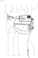
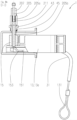
- Figs. 1a and 1b each show a perspective view of an exemplary embodiment of a drive and locking system 1 for a charging port flap 3 that is in a closed state, wherein fig. 1a show a front view on the flap 3 and fig. 1b shows a view on the backside of the flap 3.
- the flap 3 is depicted schematically, only. It is mechanically coupled to an actuating drive 5 having an electric motor and a reduction gear.
- the actuating drive 5 comprises a first housing 7 that accommodates the electric motor, the reduction gear and a motor controller.
- the reduction gear comprises an output shaft 9 for providing a torque via an opening 11 of the first housing.
- a second housing 13 having a second opening comprises two half-shells 13a, 13b and faces the opening 11 of the first housing 7.
- the hinge 15 comprises a through hole as a radial bearing for a shaft 17 of the flap 3,
- the shaft 17 of the flap 3 can be coupled the the output shaft 9 of the actuating drive 5 via the respective openings of the first housing 7 and second housing 13.
- FIGs 2a and 2b the system of figures 1a and 1b is shown for the case of an opened flap 3.
- the hinge 15 carrying the flap 3 is protruding out of the second housing 13 for the most part.
- the hinge 15 is mostly accommodated inside the second housing 13, as in figures 1a and b.
- the third housing 21 also comprises a third opening 25, through which the hinge 15 is extending.
- the flap 3 is attached to the hinge 15 and the charging port bay 23 can be closed by adjusting the flap, i.e. by moving the flap 3 to the closing position.
- the perspective rear view of fig. 3 shows the arrangement of the first housing 7 of the actuator, the second housing 13 accommodating the hinge 15, as well as the back side of the third housing 21 of the charging port bay 23.
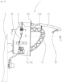
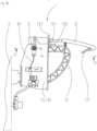
- Fig. 3 shows a perspective view on the top of the actuating drive 5, where the second housing 12 is not shown. So the coupling of the driving shaft 9 and the lever arm 43 with the actuating drive 5 can be seen.
- the output shaft 9 provides a torque to drive the hinge 15.
- Figure 5 also provides a good view on a locking system 41 for locking the flap 3, comprising a lever arm 43 and a third spring 45.
- the third spring 45 comprises a first leg 45a and a second leg 45b and is arranged around the driving shaft 9.
- the lever arm 43 comprises a fixing portion 47, which encompasses the driving shaft and is mechanically coupled to that. So the lever arm 43 can be rotated about the axis of the driving shaft 9 by driving the driving shaft 9.
- the fixing portion 47 comprises a first notch 49 in which a first leg 45a of the third spring 45 is fixed.
- a second notch or recess 49 is formed in the hinge 15, in which the second leg 45b of the third spring 45 is arranged or fixed.
- Figure 3 shows a state with the flap 3 being in the closing position and the locking system locking the flap 3.
- the locking system comprises a first locking member 65 having a first distal end 65a and a second distal end 65b.
- the first locking member 65 comprises a second Bowden Cable 67.
- the second Bowden Cable 67 comprises a disc-shaped member 69.
- the disc-shaped member 69 is attached to the holding portion 51 of the lever arm, such that the second Bowden Cable 67 is being pulled, when the lever arm 43 is being rotated in an opening direction.
- the holding portion 51 of the lever arm 43 comprises a cylindrical recess 53, inside which the disc-shaped member 69 is held. Furthermore a slit 55, through which the second Bowden Cable 67 is guided, is formed in the wall of the cylindrical recess 53 of the holding portion 51,
- Fig. 4a shows a top view on a braking device 61 of the braking system 51.
- the braking device 61 is arranged at a stationary part, e.g. at a frame of the flap 3.
- the braking device 61 is arranged at a backside of the charging port bay, i.e. at the backside of the third housing 21.
- the braking device 61 is accommodated in a forth housing 63.
- the fourth housing 63 is fixed to the third housing 21 by the help of a latching system 65.
- the fourth housing 63 can be integrally formed with the third housing 21.
- the braking device 61 comprises two elastic elements 71, e.g. made of spring steel or similar metal sheets.
- the elastic elements 71 hold the second distal end 61b of the first locking member 61, i.e. of the second Bowden Cable 67.
- the second distal end 61b of the first locking member 61 comprises a disc-shaped member 69.
- the elastic elements are bent towards each other in order to hold the disc-shaped member 69.
- An inner wall of the braking device 1 comprises two adjacent convex portions 73, which are formed such that the deformation of the elastic elements 71 is limited.
- the disc-shaped member 69 is being pushed or pulled towards the inside of the braking device, wherein the movement is supported by the second spring 75.
- the maximal deformation of the elastic elements 71 is limited by the convex portions 73 of the inner wall of the braking device 61.
- Fig. 4b shows a sectional view along the cut B-B of fig. 4a .
- a protruding element 107 of the flap 3 which is pointing in an inward direction towards the braking device 61, can be seen.
- the first locking member/the disc-shaped element 69 is in the locking position, it engages with the protruding element 107 for locking the flap 3.
- the exemplary embodiment of figures 4 to 4b also shows an optional sealing system 101, by which the braking device 61 can be sealed, i.e. protected from liquids or dust entering the braking device 61.
- the sealing system 101 comprises a plug 103, wherein the protruding element 107 pushes the plug 103 in an inward direction upon closing the flap 3.
- the plug 103 compresses a second spring 105 upon the flap 3 closing operation. If the flap 3 is being opened again, the second spring 105 pushes back the plug 103 in an outward direction, such that an opening of the braking device 61 is being closed.
- the plug 103 acts as a seal of the braking device 61.
- the first spring now is compressed, such that it can assist in pushing the disc-shaped member 69 back to the locking position in a subsequent closing process.
- the second spring 105 can push the plug 103 in an outward direction, such that the opening 111 of the braking device 61 is sealed.
- a disengagement system which provides means to implement a recovery mode for the drive and locking system 1 is disclosed.
- An exemplary embodiment of the disengagement system is illustrated in the figures 7a to 10b .
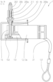
- Figure 7a shows a top view on the first half-shell 13a of the second housing 13, for the case when the flap 3 is in a closed state.
- a handle 131 is fixed to the first Bowden Cable 31 and can be pulled by a user.
- Figure 7a and fig. 7b showing a cross-sectional view along cut C-C of figure 7a illustrate the state, where the first Bowden Cable 31 was not pulled, so the system is in the normal operation state.
- the sledge 151 is being pulled along a straight part of the lever arm 43, which comprises a ramp 155.
- the lever arm 43 is forced to rotate about the axis of the driving shaft 9 and the flap 3 is opened partially.
- the flap after pulling the first Bowden Cable, the flap will be partially opened and decoupled from the actuating drive.
- This allows for a user to manually open the flap. I.e., a user can manually open the flap, even if the actuating drive is not powered or defect.
- a forth spring 157 can be coupled to the sledge 151 and the fourth housing 63, such that the sledge 151 is being pulled back to its rest position by the forth spring 157.
- the protrusion 213 of the inner axle 205 will be rotated with respect to the notch 215 of the opening of the lever arm 43.
- the flap 3 will stay decoupled from the output shaft 9 of the actuating drive, until the flap3 is moved back to the closing position, realigning the protrusion 213 and the notch 215.
- FIG. 9a The disengagement-mechanics can be seen best in figure 9a , with a cross-sectional view along line A-A shown in figure 9b , and 10a , with a cross-sectional view along line B-B shown in figure 10b .
- Figures 9a and 9b show a state where the out shaft and the lever arm 43 are engaged in a torque-proof manner, while figures 10a and 10b illustrates a disengaged state.
- a fifth spring 211 is arranged at the inner axle 205, such that it exerts a force on the inner axle 205 in an axial direction, if the inner axle is disengaged ( figures 10a, 10b ) from the lever arm 43.
- the fifth spring 211 can be arranged inside the hollow output shaft 9.
- the fifth spring 211 is arranged at an outer circumference of the inner axle, inside the hollow shaft 9, as it is shown in the example of figures 7a to 1b .
- the hollow output shaft 9 comprises a wide section 212a having a radius R1.
- the fifth spring 211 is accommodated in this wide section 211a.
- the radius R1 is larger than an inner radius R3 of a narrow section 212b of the hollow output shaft 9.
- the fifth spring 211 is confined by a step of the inner circumference of the hollow output shaft 9 between the wide section 211a and the narrow section 211b.
- the fifth spring is confined by the sleeve 207.
- the fifth spring 211 is being compressed, so as to provide a counter-force on the sleeve 207 and inner axle. So, the fifth spring 211 pushes the inner axle 205 in a direction opposite to the direction the inner axle 205 is pushed by the fin 153.
- the protrusion 213 of the sleeve 207 has an outer radius R2 ⁇ R3, such that it can be moved into the space surrounded by the wide section 212a of the hollow shaft 9 for disengaging it from the lever arm 43.
Landscapes
- Engineering & Computer Science (AREA)
- Life Sciences & Earth Sciences (AREA)
- Sustainable Development (AREA)
- Sustainable Energy (AREA)
- Chemical & Material Sciences (AREA)
- Combustion & Propulsion (AREA)
- Transportation (AREA)
- Mechanical Engineering (AREA)
- Lock And Its Accessories (AREA)
Applications Claiming Priority (1)
| Application Number | Priority Date | Filing Date | Title |
|---|---|---|---|
| DE102023100987.7A DE102023100987A1 (de) | 2023-01-17 | 2023-01-17 | Antriebs- und Verriegelungssystem für eine Klappe oder eine Tür |
Publications (1)
| Publication Number | Publication Date |
|---|---|
| EP4403736A1 true EP4403736A1 (de) | 2024-07-24 |
Family
ID=89535826
Family Applications (1)
| Application Number | Title | Priority Date | Filing Date |
|---|---|---|---|
| EP24150773.0A Pending EP4403736A1 (de) | 2023-01-17 | 2024-01-08 | Antriebs- und verriegelungssystem für eine klappe oder eine tür |
Country Status (2)
| Country | Link |
|---|---|
| EP (1) | EP4403736A1 (de) |
| DE (1) | DE102023100987A1 (de) |
Citations (4)
| Publication number | Priority date | Publication date | Assignee | Title |
|---|---|---|---|---|
| EP0608527A1 (de) * | 1992-12-15 | 1994-08-03 | WEBASTO KAROSSERIESYSTEME GmbH | Tankverschlusssystem für einen Kraftstoffbehälter eines Kraftfahrzeuges |
| FR2717210A1 (fr) * | 1994-03-09 | 1995-09-15 | Rohee Rene Denis Georges | Dispositif de verrouillage automatique d'un battant de volet. |
| WO2007116700A1 (ja) * | 2006-03-28 | 2007-10-18 | Webasto Ag | リンク機構 |
| DE102021127778A1 (de) * | 2020-11-01 | 2022-05-05 | Illinois Tool Works Inc. | Klappabdeckung-betätigungsanordnung und klappabdeckungsanordnung für einen betankungsanschluss oder ladeanschluss, welche diese aufweist |
Family Cites Families (4)
| Publication number | Priority date | Publication date | Assignee | Title |
|---|---|---|---|---|
| US10113339B2 (en) * | 2015-05-06 | 2018-10-30 | Kiekert Ag | Fuel door actuator |
| CN111086385B (zh) * | 2018-10-23 | 2025-04-11 | 伊利诺斯工具制品有限公司 | 翻盖组件及其翻盖的致动结构 |
| DE102021127868B4 (de) * | 2020-11-01 | 2023-05-04 | Illinois Tool Works Inc. | Betätigungsanordnung und klappabdeckungsanordnung für einen betankungsanschluss oder ladeanschluss |
| DE102022121106B4 (de) * | 2022-01-20 | 2024-02-08 | Illinois Tool Works Inc. | Betätigungsmechanismus zum betätigen von lade-, tank- oder serviceklappen |
-
2023
- 2023-01-17 DE DE102023100987.7A patent/DE102023100987A1/de active Pending
-
2024
- 2024-01-08 EP EP24150773.0A patent/EP4403736A1/de active Pending
Patent Citations (4)
| Publication number | Priority date | Publication date | Assignee | Title |
|---|---|---|---|---|
| EP0608527A1 (de) * | 1992-12-15 | 1994-08-03 | WEBASTO KAROSSERIESYSTEME GmbH | Tankverschlusssystem für einen Kraftstoffbehälter eines Kraftfahrzeuges |
| FR2717210A1 (fr) * | 1994-03-09 | 1995-09-15 | Rohee Rene Denis Georges | Dispositif de verrouillage automatique d'un battant de volet. |
| WO2007116700A1 (ja) * | 2006-03-28 | 2007-10-18 | Webasto Ag | リンク機構 |
| DE102021127778A1 (de) * | 2020-11-01 | 2022-05-05 | Illinois Tool Works Inc. | Klappabdeckung-betätigungsanordnung und klappabdeckungsanordnung für einen betankungsanschluss oder ladeanschluss, welche diese aufweist |
Also Published As
| Publication number | Publication date |
|---|---|
| DE102023100987A1 (de) | 2024-07-18 |
Similar Documents
| Publication | Publication Date | Title |
|---|---|---|
| CN108222713B (zh) | 调平的开启控制装置 | |
| ES2911352T3 (es) | Sistema de liberación de puerta y método de accionamiento del mismo | |
| US12163360B2 (en) | Closure latch assembly equipped with single ratchet/pawl latch mechanism and a power latch release mechanism with a dual-stage gear train | |
| US4796932A (en) | Remote release and pull-down unit | |
| CN115053044B (zh) | 针对伺服控制进行优化的动力门单元 | |
| US7059640B2 (en) | Lock, especially for the doors, flaps or the like, of motor vehicles | |
| US20250382837A1 (en) | Distributed control system for servo controlled powered door actuator | |
| EP3956533B1 (de) | Dienstübersteuerung für ein verriegelungssystem mit elektrischer lösung | |
| US20070194599A1 (en) | Electromechanical strut | |
| US20060082188A1 (en) | Electromechanical strut | |
| CN108222711A (zh) | 智能闩锁 | |
| JP5974080B2 (ja) | 車外ミラー調節手段のための自動切り替えクラッチ | |
| EP3599331B1 (de) | Zuziehüberbrückungsmechanismus für verriegelungsanordnung | |
| JP4009860B2 (ja) | パワースライディングドア開閉システム | |
| EP1153185B1 (de) | Kraftangetriebene türverriegelungsvorrichtung | |
| EP4403736A1 (de) | Antriebs- und verriegelungssystem für eine klappe oder eine tür | |
| US12018517B2 (en) | Motor vehicle latch assembly with manual release | |
| WO2020213199A1 (ja) | ドアロック装置 | |
| EP1826047A2 (de) | Elektromechanische Strebe | |
| JP4598668B2 (ja) | 車両用ドアロック装置 | |
| CN110834524A (zh) | 具有防夹保护件的机动车辆闭合面板和用于闭合面板的防夹保护件 | |
| JP4105806B2 (ja) | ドアロック操作装置 | |
| JPH0466982B2 (de) | ||
| CN110939346B (zh) | 用于动力门系统的离合器组件 | |
| US20020046496A1 (en) | Actuator for operating vehicle door |
Legal Events
| Date | Code | Title | Description |
|---|---|---|---|
| PUAI | Public reference made under article 153(3) epc to a published international application that has entered the european phase |
Free format text: ORIGINAL CODE: 0009012 |
|
| STAA | Information on the status of an ep patent application or granted ep patent |
Free format text: STATUS: THE APPLICATION HAS BEEN PUBLISHED |
|
| AK | Designated contracting states |
Kind code of ref document: A1 Designated state(s): AL AT BE BG CH CY CZ DE DK EE ES FI FR GB GR HR HU IE IS IT LI LT LU LV MC ME MK MT NL NO PL PT RO RS SE SI SK SM TR |
|
| STAA | Information on the status of an ep patent application or granted ep patent |
Free format text: STATUS: REQUEST FOR EXAMINATION WAS MADE |
|
| 17P | Request for examination filed |
Effective date: 20250115 |