EP4403476A1 - Stationärer ionen-/plasmamotor - Google Patents
Stationärer ionen-/plasmamotor Download PDFInfo
- Publication number
- EP4403476A1 EP4403476A1 EP22867834.8A EP22867834A EP4403476A1 EP 4403476 A1 EP4403476 A1 EP 4403476A1 EP 22867834 A EP22867834 A EP 22867834A EP 4403476 A1 EP4403476 A1 EP 4403476A1
- Authority
- EP
- European Patent Office
- Prior art keywords
- discharge chamber
- magnetically conductive
- wave
- engine
- conductive housing
- Prior art date
- Legal status (The legal status is an assumption and is not a legal conclusion. Google has not performed a legal analysis and makes no representation as to the accuracy of the status listed.)
- Pending
Links
Images

Classifications
-
- B—PERFORMING OPERATIONS; TRANSPORTING
- B64—AIRCRAFT; AVIATION; COSMONAUTICS
- B64G—COSMONAUTICS; VEHICLES OR EQUIPMENT THEREFOR
- B64G1/00—Cosmonautic vehicles
- B64G1/22—Parts of, or equipment specially adapted for fitting in or to, cosmonautic vehicles
- B64G1/40—Arrangements or adaptations of propulsion systems
- B64G1/411—Electric propulsion
- B64G1/413—Ion or plasma engines
-
- B—PERFORMING OPERATIONS; TRANSPORTING
- B64—AIRCRAFT; AVIATION; COSMONAUTICS
- B64G—COSMONAUTICS; VEHICLES OR EQUIPMENT THEREFOR
- B64G1/00—Cosmonautic vehicles
- B64G1/22—Parts of, or equipment specially adapted for fitting in or to, cosmonautic vehicles
- B64G1/40—Arrangements or adaptations of propulsion systems
-
- F—MECHANICAL ENGINEERING; LIGHTING; HEATING; WEAPONS; BLASTING
- F03—MACHINES OR ENGINES FOR LIQUIDS; WIND, SPRING, OR WEIGHT MOTORS; PRODUCING MECHANICAL POWER OR A REACTIVE PROPULSIVE THRUST, NOT OTHERWISE PROVIDED FOR
- F03H—PRODUCING A REACTIVE PROPULSIVE THRUST, NOT OTHERWISE PROVIDED FOR
- F03H1/00—Using plasma to produce a reactive propulsive thrust
- F03H1/0037—Electrostatic ion thrusters
- F03H1/0062—Electrostatic ion thrusters grid-less with an applied magnetic field
- F03H1/0075—Electrostatic ion thrusters grid-less with an applied magnetic field with an annular channel; Hall-effect thrusters with closed electron drift
-
- H—ELECTRICITY
- H05—ELECTRIC TECHNIQUES NOT OTHERWISE PROVIDED FOR
- H05H—PLASMA TECHNIQUE; PRODUCTION OF ACCELERATED ELECTRICALLY-CHARGED PARTICLES OR OF NEUTRONS; PRODUCTION OR ACCELERATION OF NEUTRAL MOLECULAR OR ATOMIC BEAMS
- H05H1/00—Generating plasma; Handling plasma
- H05H1/54—Plasma accelerators
Definitions
- the invention relates to the field of space technology and can be used in electric jet engines, and also in vacuum-plasma process units.
- SPEs Hall-effect stationary ion-plasma engines
- a stationary ion-plasma engine which comprises a magnetically conductive housing, in which a discharge chamber with a ring-shaped ionization and acceleration channel is arranged, which has an outer and an inner cylindrical surface, is made of electrically insulating material and has an open outlet on one side, and on the opposite side is, via a fastening means, connected to the magnetically conductive housing of the engine, a hollow annular gas-distributing anode, which is in communication with a tank of gas propellant, and a cathode, which is fastened to the magnetically conductive housing, are arranged in the discharge chamber, wherein the engine has a magnetic system, which consists of coils with magnetically conductive cores and a magnetically conductive housing ( Russian patent no.
- the means for fastening the discharge chamber to the magnetically conductive housing is embodied in the form of non-magnetic pins made of stainless steel, which are arranged in an insulating bushing in the wall of the discharge chamber.
- a stationary ion-plasma engine which comprises a magnetically conductive housing, in which a discharge chamber with a ring-shaped ionization and acceleration channel is arranged, which has an outer and an inner cylindrical surface, is made of electrically insulating material and has an open outlet on one side and on the opposite side is, via a fastening means, connected to the magnetically conductive housing of the engine, a hollow annular gas-distributing anode, which is in communication with a tank of gas propellant, and a cathode, which is fastened to the magnetically conductive housing, are arranged in the discharge chamber, wherein the engine has a magnetic system, which consists of coils with magnetically conductive cores and a magnetically conductive housing.
- the method developed for designing an SPT makes it possible to assess the influence of the thermal state of the engine, but does not eliminate the drawbacks of its structure.
- a stationary plasma engine which comprises a magnetically conductive housing, in which a discharge chamber with a ring-shaped ionization and acceleration channel is arranged, which has an outer and an inner cylindrical surface, is made of electrically insulating material and has an open outlet on one side and on the opposite side is, by an annular metal cage via a fastening means, connected to the magnetically conductive housing of the engine, a hollow annular gas-distributing anode, which is in communication with a tank of gas propellant, and a cathode, which is fastened to the magnetically conductive housing, are arranged in the discharge chamber, wherein the engine has a magnetic system, which consists of coils with magnetically conductive coils and a magnetically conductive housing.
- the ceramic discharge chamber is embodied, as a rule, in the form of a monolithic component with an annular slot which forms the acceleration channel.
- the discharge chamber is fastened to the magnetic system using a bridging metal cage which, as an element with increased heat resistance, reduces the amount of heat transferred from the anode and ceramic chamber to the magnetic system.
- This stationary ion-plasma engine is selected as the closest prior art.
- the problem addressed by the invention is that of creating a structure of a stationary plasma engine in which a ceramic discharge chamber would be fully freed from temperature deformations of structural elements of the engine, wherein the positioning of the discharge chamber with respect to the axis of the engine would be unambiguous in any operating conditions, and assembling the engine would be made simpler.
- a stationary ion-plasma engine which comprises a magnetically conductive housing, in which a discharge chamber with a ring-shaped ionization and acceleration channel is arranged, which has an outer and an inner annular surface, is made of electrically insulating material and has an open outlet on one side and on the opposite, bottom side is, via a fastening means, embodied in the form of an annular metal cage, connected to the magnetically conductive housing of the engine, a hollow annular gas-distributing anode, which is in communication with a tank of gas propellant, and a cathode, which is fastened to the magnetically conductive housing, are arranged in the discharge chamber, wherein the engine has a magnetic system, which consists of coils with magnetically conductive cores and a magnetically conductive housing; according to the invention the outer and the inner annular surface of the discharge chamber are described by wave-shaped generating lines which create concentric slots on the annular surfaces of the discharge chamber, the means for fasten
- a wave-shaped generating line of the discharge chamber is advantageously in the form of a sinusoid.
- the annular metal cage is advantageously manufactured from material with a minimal linear expansion coefficient.
- the annular metal cage is fastened to the magnetically conductive housing by means of a screw and nut, which screw is embodied in the form of a separate component or welded to the cage.
- the claimed features are essential and are mutually connected to form a stable set of essential features which is sufficient for obtaining the required technical result.
- the technical result of the invention is to make it simpler to assemble an ion-plasma engine by automatically positioning its discharge chamber with respect to the axis of the engine while simultaneously freeing the discharge chamber from temperature deformations of the structural elements of the engine.
- the proposed stationary ion-plasma engine comprises a magnetically conductive housing 1, in which a discharge chamber 2 with a ring-shaped ionization and acceleration channel 3 is arranged.
- the discharge chamber 2 is made of electrically insulating material and has an outer and an inner annular surface 4 and 5.
- the discharge chamber has an open outlet 6 on one side and on the opposite side is, via a fastening means embodied in the form of an annular metal cage 7, connected to the magnetically conductive housing 1 of the engine using fastening elements 8 and 9.
- a hollow annular gas-distributing anode 10 which is in communication with a tank of gas propellant (the tank is not shown specifically), and a cathode (which is not shown specifically), which is fastened to the magnetically conductive housing 1 using a bracket 11, are arranged in the discharge chamber 2.
- the cathode is fastened to the magnetically conductive housing 1 using a bracket 11 to the side of the engine.
- it can be arranged either to the side of the engine or on the central axis of the engine. In practice both variant arrangements of the cathode are used.
- the stationary ion-plasma engine has a magnetic system, which consists of coils with magnetically conductive cores 12 and 13 and a magnetically conductive housing 1.
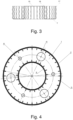
- the outer and the inner annular surface 4 and 5 of the discharge chamber 1 are described by wave-shaped generating lines which create concentric slots 14 on the annular surfaces of the discharge chamber.
- a wave-shaped generating line of the discharge chamber 2 is advantageously in the form of a sinusoid.
- the annular discharge chamber 2 is enclosed by the annular metal cage 7, which is fastened to the magnetically conductive housing 1 using fastening elements 8 and 9.
- the annular metal cage 7 is manufactured from material with a minimal linear expansion coefficient.
- Openings 18 which serve to accommodate the fastening elements 8 by means of which the cage 7 is fastened to the magnetically conductive housing 1, and also large-diameter openings 19 which serve for elements of the anode 10, which are under a potential (voltage) and provide a necessary insulating gap between these elements and the cage 7, to pass through, are made in the flat bottom base of the cage 7.
- the fastening elements in the form of screws 8, by means of which the cage 7 is fastened to the magnetically conductive housing 1, can be embodied in the form of separate screws, the diameter of the head 20 of which is larger than the diameter of an opening 18, or are welded (which is not shown specifically) to the bottom part of the cage 7.
- a recess 21 with dimensions which exceed the dimensions of the head, taking into account changes in dimensions during heating, is provided for the head 20.
- the stationary ion-plasma engine with an innovative subassembly for fastening the discharge chamber to the magnetically conductive housing proposed in the invention operates in the following way:
- the grooves in the walls of the metal cage 7, which separate the walls into the separate wave-shaped petals 16 and 17, are made so that they stop at a flat base of the cage 7 which is not less than 0.5 mm in size in order to exclude the presence of closed loops in the side walls of the cage 7, which can create a force action on the discharge chamber when they undergo heat deformations ( fig. 4 ) .
- the metal cage 7 is fastened to the magnetic core 1 using the fastening elements 8 and 9 along with spring balancing spacers which eliminate the influence of heat deformations of the fastening elements 8.
- the proposed embodiment of a stationary ion-plasma engine makes it simpler to assemble the ion-plasma engine by automatically positioning its discharge chamber with respect to the axis of the engine while simultaneously freeing the discharge chamber from temperature deformations of structural elements of the engine.
- the structure of the cage 7 with separate petals 16 and 17 excludes a force action of the cage 7 on the discharge chamber 2 when the diameters of the generating lines of the petals 16 and 17 are changed when the engine is in operation, i.e. when the cage is heated to high temperatures (1000°C and higher).
- the wave-shaped petals 16 and 17, which have wave-curvature radii which are somewhat smaller than the radii of the concentric slots 14 in the discharge chamber 2, also have the ability to move along the axis of the engine when it is heated in the process of operation to critically high temperatures, which ensures the difference in temperature linear expansion coefficients between the material of the metal cage 7 and the material of the ceramic discharge chamber 2 is compensated for without interfering with the positioning of the chamber 2 with respect to the magnetically conductive housing 1.
Landscapes
- Engineering & Computer Science (AREA)
- Chemical & Material Sciences (AREA)
- Combustion & Propulsion (AREA)
- Physics & Mathematics (AREA)
- Plasma & Fusion (AREA)
- Remote Sensing (AREA)
- Aviation & Aerospace Engineering (AREA)
- Mechanical Engineering (AREA)
- General Engineering & Computer Science (AREA)
- Spectroscopy & Molecular Physics (AREA)
- Plasma Technology (AREA)
Applications Claiming Priority (2)
| Application Number | Priority Date | Filing Date | Title |
|---|---|---|---|
| UAA202105136A UA129566C2 (uk) | 2021-09-13 | 2021-09-13 | Стаціонарний іонно-плазмовий двигун |
| PCT/UA2022/000055 WO2023038611A1 (ru) | 2021-09-13 | 2022-09-19 | Стационарный ионно-плазменный двигатель |
Publications (3)
| Publication Number | Publication Date |
|---|---|
| EP4403476A1 true EP4403476A1 (de) | 2024-07-24 |
| EP4403476A8 EP4403476A8 (de) | 2024-08-28 |
| EP4403476A4 EP4403476A4 (de) | 2025-10-01 |
Family
ID=85507528
Family Applications (1)
| Application Number | Title | Priority Date | Filing Date |
|---|---|---|---|
| EP22867834.8A Pending EP4403476A4 (de) | 2021-09-13 | 2022-09-19 | Stationärer ionen-/plasmamotor |
Country Status (3)
| Country | Link |
|---|---|
| EP (1) | EP4403476A4 (de) |
| UA (1) | UA129566C2 (de) |
| WO (1) | WO2023038611A1 (de) |
Families Citing this family (1)
| Publication number | Priority date | Publication date | Assignee | Title |
|---|---|---|---|---|
| CN116812177B (zh) * | 2023-07-17 | 2025-11-14 | 上海宇航系统工程研究所 | 一种用于航天器舱外的抬升机构 |
Family Cites Families (11)
| Publication number | Priority date | Publication date | Assignee | Title |
|---|---|---|---|---|
| EP0541309B1 (de) * | 1991-11-04 | 1996-01-17 | Fakel Enterprise | Plasmabeschleuniger mit geschlossener Elektronenlaufbahn |
| US6208080B1 (en) * | 1998-06-05 | 2001-03-27 | Primex Aerospace Company | Magnetic flux shaping in ion accelerators with closed electron drift |
| FR2782884B1 (fr) * | 1998-08-25 | 2000-11-24 | Snecma | Propulseur a plasma a derive fermee d'electrons adapte a de fortes charges thermiques |
| US9447779B2 (en) * | 2006-11-09 | 2016-09-20 | Alexander Kapulkin | Low-power hall thruster |
| FR2950114B1 (fr) * | 2009-09-17 | 2012-07-06 | Snecma | Moteur a effet hall avec refroidissement de la ceramique interne |
| RU2527898C1 (ru) * | 2013-04-17 | 2014-09-10 | Федеральное государственное бюджетное образовательное учреждение высшего профессионального образования "Московский государственный технический университет радиотехники, электроники и автоматики" | Стационарный плазменный двигатель малой мощности |
| CN104595139A (zh) * | 2015-01-23 | 2015-05-06 | 哈尔滨工业大学 | 一种圆柱型会切磁场推力器 |
| CN106321389A (zh) * | 2016-09-19 | 2017-01-11 | 哈尔滨工业大学 | 霍尔推力器的镂空磁屏结构 |
| FR3080154B1 (fr) * | 2018-04-13 | 2021-02-19 | Safran Aircraft Engines | Procede de fabrication d'un propulseur electrique |
| FR3093771B1 (fr) * | 2019-03-15 | 2021-04-02 | Safran Aircraft Engines | Fond de chambre pour propulseur plasmique |
| CN112483341B (zh) * | 2020-11-25 | 2022-06-14 | 哈尔滨工业大学 | 霍尔推力器导热支架及含有该支架的霍尔推力器 |
-
2021
- 2021-09-13 UA UAA202105136A patent/UA129566C2/uk unknown
-
2022
- 2022-09-19 EP EP22867834.8A patent/EP4403476A4/de active Pending
- 2022-09-19 WO PCT/UA2022/000055 patent/WO2023038611A1/ru not_active Ceased
Also Published As
| Publication number | Publication date |
|---|---|
| EP4403476A4 (de) | 2025-10-01 |
| WO2023038611A1 (ru) | 2023-03-16 |
| UA129566C2 (uk) | 2025-06-04 |
| EP4403476A8 (de) | 2024-08-28 |
Similar Documents
| Publication | Publication Date | Title |
|---|---|---|
| US5945781A (en) | Ion source with closed electron drift | |
| Goebel et al. | High-current lanthanum hexaboride hollow cathode for high-power Hall thrusters | |
| US10269526B2 (en) | Hall current plasma source having a center-mounted cathode or a surface-mounted cathode | |
| JP3655184B2 (ja) | 完全に一体化された電極貫通主絶縁体を有するレーザチャンバ | |
| EP2671430B1 (de) | Hochleistungs-induktionsplasmabrenner | |
| KR102697098B1 (ko) | 플라즈마 구속 시스템 및 사용하기 위한 방법 | |
| US8519607B2 (en) | Spark plug electrode configuration | |
| EP0502829A1 (de) | Vorrichtung mit ungeheizter Kathode zur dynamischen Erzeugung von Plasma | |
| EP4403476A1 (de) | Stationärer ionen-/plasmamotor | |
| EP3314989B1 (de) | Induktionsplasmabrenner mit höherer plasmaenergiedichte und teilaustauschverfahren dafür | |
| UA57770C2 (uk) | Плазмовий ракетний двигун із замкнутим дрейфом електронів | |
| US11346330B1 (en) | Additively manufactured components for electric propulsion thrusters | |
| CN115681052B (zh) | 霍尔推力器、具有其的设备及其使用方法 | |
| US3413509A (en) | Electrode structure with buffer coil | |
| JP4905704B2 (ja) | 点火補助具およびこれを備えた冷陰極電離真空計 | |
| US20060081185A1 (en) | Thermal management of dielectric components in a plasma discharge device | |
| Gallimore et al. | Anode power deposition in magnetoplasmadynamic thrusters | |
| CN114151298B (zh) | 平板型外部放电式霍尔推力器 | |
| Khayms et al. | Fifty-watt Hall thruster for microsatellites | |
| RU2191289C2 (ru) | Плазменный двигатель с замкнутым дрейфом электронов | |
| US3452249A (en) | Method and apparatus for containing a plasma produced by opposed electrodes | |
| Zuo et al. | Design of the RF negative hydrogen ion source at HUST | |
| CN115822906B (zh) | 一种霍尔推力器 | |
| US3437871A (en) | Plasma containment apparatus with ion cyclotron resonance heating | |
| KR20030003827A (ko) | 초강력 세라믹 자석을 이용한 공동형 플라즈마 토치장치 |
Legal Events
| Date | Code | Title | Description |
|---|---|---|---|
| STAA | Information on the status of an ep patent application or granted ep patent |
Free format text: STATUS: THE INTERNATIONAL PUBLICATION HAS BEEN MADE |
|
| PUAI | Public reference made under article 153(3) epc to a published international application that has entered the european phase |
Free format text: ORIGINAL CODE: 0009012 |
|
| STAA | Information on the status of an ep patent application or granted ep patent |
Free format text: STATUS: REQUEST FOR EXAMINATION WAS MADE |
|
| 17P | Request for examination filed |
Effective date: 20240408 |
|
| AK | Designated contracting states |
Kind code of ref document: A1 Designated state(s): AL AT BE BG CH CY CZ DE DK EE ES FI FR GB GR HR HU IE IS IT LI LT LU LV MC MK MT NL NO PL PT RO RS SE SI SK SM TR |
|
| XX | Miscellaneous (additional remarks) |
Free format text: A REQUEST FOR RESTORATION OF THE RIGHT OF PRIORITY BY THE EPO AS DESIGNATED OFFICE HAS BEEN GRANTED (R. 49TER.2 PCT, ART.122 EPC) |
|
| DAV | Request for validation of the european patent (deleted) | ||
| DAX | Request for extension of the european patent (deleted) | ||
| REG | Reference to a national code |
Ref country code: DE Ref legal event code: R079 Free format text: PREVIOUS MAIN CLASS: B64G0001400000 Ipc: F03H0001000000 |
|
| A4 | Supplementary search report drawn up and despatched |
Effective date: 20250902 |
|
| RIC1 | Information provided on ipc code assigned before grant |
Ipc: F03H 1/00 20060101AFI20250827BHEP Ipc: B64G 1/40 20060101ALI20250827BHEP Ipc: H05H 1/54 20060101ALI20250827BHEP |