EP4403452A1 - System und verfahren zur behandlung von boil-off-gas eines schiffs - Google Patents
System und verfahren zur behandlung von boil-off-gas eines schiffs Download PDFInfo
- Publication number
- EP4403452A1 EP4403452A1 EP21957641.0A EP21957641A EP4403452A1 EP 4403452 A1 EP4403452 A1 EP 4403452A1 EP 21957641 A EP21957641 A EP 21957641A EP 4403452 A1 EP4403452 A1 EP 4403452A1
- Authority
- EP
- European Patent Office
- Prior art keywords
- gas
- boil
- compressor
- refrigerant
- heat exchanger
- Prior art date
- Legal status (The legal status is an assumption and is not a legal conclusion. Google has not performed a legal analysis and makes no representation as to the accuracy of the status listed.)
- Pending
Links
Images


Classifications
-
- F—MECHANICAL ENGINEERING; LIGHTING; HEATING; WEAPONS; BLASTING
- F17—STORING OR DISTRIBUTING GASES OR LIQUIDS
- F17C—VESSELS FOR CONTAINING OR STORING COMPRESSED, LIQUEFIED OR SOLIDIFIED GASES; FIXED-CAPACITY GAS-HOLDERS; FILLING VESSELS WITH, OR DISCHARGING FROM VESSELS, COMPRESSED, LIQUEFIED, OR SOLIDIFIED GASES
- F17C6/00—Methods and apparatus for filling vessels not under pressure with liquefied or solidified gases
-
- B—PERFORMING OPERATIONS; TRANSPORTING
- B63—SHIPS OR OTHER WATERBORNE VESSELS; RELATED EQUIPMENT
- B63J—AUXILIARIES ON VESSELS
- B63J4/00—Arrangements of installations for treating ballast water, waste water, sewage, sludge, or refuse, or for preventing environmental pollution not otherwise provided for
-
- B—PERFORMING OPERATIONS; TRANSPORTING
- B63—SHIPS OR OTHER WATERBORNE VESSELS; RELATED EQUIPMENT
- B63B—SHIPS OR OTHER WATERBORNE VESSELS; EQUIPMENT FOR SHIPPING
- B63B17/00—Vessels parts, details, or accessories, not otherwise provided for
- B63B17/0027—Tanks for fuel or the like ; Accessories therefor, e.g. tank filler caps
-
- B—PERFORMING OPERATIONS; TRANSPORTING
- B63—SHIPS OR OTHER WATERBORNE VESSELS; RELATED EQUIPMENT
- B63B—SHIPS OR OTHER WATERBORNE VESSELS; EQUIPMENT FOR SHIPPING
- B63B25/00—Load-accommodating arrangements, e.g. stowing, trimming; Vessels characterised thereby
- B63B25/02—Load-accommodating arrangements, e.g. stowing, trimming; Vessels characterised thereby for bulk goods
- B63B25/08—Load-accommodating arrangements, e.g. stowing, trimming; Vessels characterised thereby for bulk goods fluid
- B63B25/12—Load-accommodating arrangements, e.g. stowing, trimming; Vessels characterised thereby for bulk goods fluid closed
- B63B25/16—Load-accommodating arrangements, e.g. stowing, trimming; Vessels characterised thereby for bulk goods fluid closed heat-insulated
-
- B—PERFORMING OPERATIONS; TRANSPORTING
- B63—SHIPS OR OTHER WATERBORNE VESSELS; RELATED EQUIPMENT
- B63H—MARINE PROPULSION OR STEERING
- B63H21/00—Use of propulsion power plant or units on vessels
- B63H21/38—Apparatus or methods specially adapted for use on marine vessels, for handling power plant or unit liquids, e.g. lubricants, coolants, fuels or the like
-
- F—MECHANICAL ENGINEERING; LIGHTING; HEATING; WEAPONS; BLASTING
- F02—COMBUSTION ENGINES; HOT-GAS OR COMBUSTION-PRODUCT ENGINE PLANTS
- F02M—SUPPLYING COMBUSTION ENGINES IN GENERAL WITH COMBUSTIBLE MIXTURES OR CONSTITUENTS THEREOF
- F02M21/00—Apparatus for supplying engines with non-liquid fuels, e.g. gaseous fuels stored in liquid form
- F02M21/02—Apparatus for supplying engines with non-liquid fuels, e.g. gaseous fuels stored in liquid form for gaseous fuels
- F02M21/0218—Details on the gaseous fuel supply system, e.g. tanks, valves, pipes, pumps, rails, injectors or mixers
- F02M21/0221—Fuel storage reservoirs, e.g. cryogenic tanks
-
- F—MECHANICAL ENGINEERING; LIGHTING; HEATING; WEAPONS; BLASTING
- F02—COMBUSTION ENGINES; HOT-GAS OR COMBUSTION-PRODUCT ENGINE PLANTS
- F02M—SUPPLYING COMBUSTION ENGINES IN GENERAL WITH COMBUSTIBLE MIXTURES OR CONSTITUENTS THEREOF
- F02M21/00—Apparatus for supplying engines with non-liquid fuels, e.g. gaseous fuels stored in liquid form
- F02M21/02—Apparatus for supplying engines with non-liquid fuels, e.g. gaseous fuels stored in liquid form for gaseous fuels
- F02M21/0218—Details on the gaseous fuel supply system, e.g. tanks, valves, pipes, pumps, rails, injectors or mixers
- F02M21/0287—Details on the gaseous fuel supply system, e.g. tanks, valves, pipes, pumps, rails, injectors or mixers characterised by the transition from liquid to gaseous phase ; Injection in liquid phase; Cooling and low temperature storage
-
- F—MECHANICAL ENGINEERING; LIGHTING; HEATING; WEAPONS; BLASTING
- F02—COMBUSTION ENGINES; HOT-GAS OR COMBUSTION-PRODUCT ENGINE PLANTS
- F02M—SUPPLYING COMBUSTION ENGINES IN GENERAL WITH COMBUSTIBLE MIXTURES OR CONSTITUENTS THEREOF
- F02M25/00—Engine-pertinent apparatus for adding non-fuel substances or small quantities of secondary fuel to combustion-air, main fuel or fuel-air mixture
- F02M25/08—Engine-pertinent apparatus for adding non-fuel substances or small quantities of secondary fuel to combustion-air, main fuel or fuel-air mixture adding fuel vapours drawn from engine fuel reservoir
- F02M25/0836—Arrangement of valves controlling the admission of fuel vapour to an engine, e.g. valve being disposed between fuel tank or absorption canister and intake manifold
-
- F—MECHANICAL ENGINEERING; LIGHTING; HEATING; WEAPONS; BLASTING
- F02—COMBUSTION ENGINES; HOT-GAS OR COMBUSTION-PRODUCT ENGINE PLANTS
- F02M—SUPPLYING COMBUSTION ENGINES IN GENERAL WITH COMBUSTIBLE MIXTURES OR CONSTITUENTS THEREOF
- F02M25/00—Engine-pertinent apparatus for adding non-fuel substances or small quantities of secondary fuel to combustion-air, main fuel or fuel-air mixture
- F02M25/08—Engine-pertinent apparatus for adding non-fuel substances or small quantities of secondary fuel to combustion-air, main fuel or fuel-air mixture adding fuel vapours drawn from engine fuel reservoir
- F02M25/0872—Details of the fuel vapour pipes or conduits
-
- F—MECHANICAL ENGINEERING; LIGHTING; HEATING; WEAPONS; BLASTING
- F17—STORING OR DISTRIBUTING GASES OR LIQUIDS
- F17C—VESSELS FOR CONTAINING OR STORING COMPRESSED, LIQUEFIED OR SOLIDIFIED GASES; FIXED-CAPACITY GAS-HOLDERS; FILLING VESSELS WITH, OR DISCHARGING FROM VESSELS, COMPRESSED, LIQUEFIED, OR SOLIDIFIED GASES
- F17C9/00—Methods or apparatus for discharging liquefied or solidified gases from vessels not under pressure
- F17C9/02—Methods or apparatus for discharging liquefied or solidified gases from vessels not under pressure with change of state, e.g. vaporisation
Definitions
- liquefied gas such as liquefied natural gas (LNG)
- LNG liquefied natural gas
- LNG emits little or no air pollutants during a liquefaction process and thus can be considered as an eco-friendly fuel with less emission of air pollutants during combustion.
- LNG is a colorless and transparent liquid obtained by cooling natural gas containing methane as a main component to about -163°C, and has a volume of about 1/600 that of natural gas.
- liquefaction of natural gas allows efficient transportation of natural gas.
- Examples of the method of reliquefying boil-off gas include providing a refrigeration cycle using a separate refrigerant to reliquefy boil-off gas through heat exchange with the refrigerant, reliquefying boil-off gas using boil-off gas itself as a refrigerant without a separate refrigerant, and the like.
- the DFDE engine uses an Otto cycle consisting of four strokes, in which natural gas at a relatively low pressure of about 5.5 barg is injected into a combustion air inlet and then compressed by a piston moving upward.
- the applicants of the present invention invented a method of reliquefying boil-off gas using the boil-off gas itself as a refrigerant without a separate refrigerant, wherein boil-off gas compressed by a compressor is cooled through heat exchange with uncompressed boil-off gas to be introduced into the compressor and is then expanded by a J-T valve or the like to achieve partial reliquefaction of boil-off gas.
- a partial reliquefaction system PRS
- the PRS When the amount of boil-off gas to be reliquefied is large, such as when the amount of liquefied gas in the storage tank is large and the amount of boil-off gas generated therefrom is thus large, or when a ship is at anchor or sails at low speed and the amount of boil-off gas consumed by an engine is thus low, the PRS alone cannot satisfy a required reliquefaction rate. Accordingly, the applicants of the present invention invented an improved PRS that can reliquefy much more boil-off gas.
- Such a compressor 10A or 10B provided to supply fuel is designed to meet fuel supply requirements for a corresponding engine and is duplicated as classification societies require that an additional redundant compressor be provided in case of compressor failure.
- the two compressors may both be operated.
- low energy efficiency due to high electricity consumption for operation of both the high-pressure compressors and high installation costs for the two high-pressure compressors.
- the refrigerant circulation line may include: a refrigerant compression unit receiving the refrigerant discharged from the heat exchanger after heat exchange and compressing the received refrigerant; and a refrigerant expansion unit receiving the refrigerant compressed by the refrigerant compression unit and having passed through the heat exchanger, expanding and cooling the received refrigerant, and supplying the cooled refrigerant to the heat exchanger.
- the boil-off gas treatment system may further include: a boil-off gas supply line along which boil-off gas is supplied from the storage tank to the first compressor or the second compressor through the heat exchanger; a first fuel supply line disposed downstream of the first compressor and connected to the propulsion engine; a reliquefaction line along which boil-off gas compressed while passing through part of the first compressor or through the second compressor is supplied to the heat exchanger to be cooled and is returned to the storage tank; and a second fuel supply line along which boil-off gas compressed while passing through part of the first compressor or through the second compressor is supplied to the power generation engine.
- the boil-off gas treatment system may further include: a liquefied gas supply line along which liquefied gas stored in the storage tank is supplied as fuel to the propulsion engine; a compression pump disposed on the liquefied gas supply line and pressurizing the liquefied gas to a fuel supply pressure required for the propulsion engine; and a vaporizer heating the liquefied gas pressurized by the compression pump.
- the first compressor When the ship is underway, the first compressor may be operated to compress boil-off gas generated in the storage tank and supply the compressed boil-off gas to the propulsion engine and the power generation engine and surplus compressed gas may be cooled by the heat exchanger, and, when the ship is at anchor, the second compressor may be operated to compress boil-off gas generated in the storage tank and to supply the compressed boil-off gas to the power generation engine and surplus compressed gas may be cooled by the heat exchanger.
- the refrigerant circulated along the refrigerant circulation line may be nitrogen.
- a boil-off gas treatment method of a ship including a propulsion engine and a power generation engine supplied with fuel at a lower pressure than the propulsion engine,
- the first compressor When the ship is underway, the first compressor may be operated to compress boil-off gas generated in the storage tank and supply the compressed boil-off gas to the propulsion engine and the power generation engine and surplus compressed gas may be cooled by the heat exchanger, and, when the ship is at anchor, the second compressor may be operated to compress boil-off gas generated in the storage tank and to supply the compressed boil-off gas to the power generation engine and surplus compressed gas may be cooled by the heat exchanger.
- the refrigerant circulated along the refrigerant circulation line may be compressed by a refrigerant compression unit, cooled through the heat exchanger, expanded and cooled by a refrigerant expansion unit, and supplied to the heat exchanger as a cold heat source, wherein the refrigerant compression unit may be connected to the refrigerant expansion unit to compress the refrigerant using expansion energy of the refrigerant transmitted from the refrigerant expansion unit.
- the present invention provides a boil-off gas treatment system for a ship including a propulsion engine and a power generation engine supplied with fuel at a lower pressure than the propulsion engine, wherein a first compressor compressing boil-off gas to a fuel supply pressure required for the propulsion engine and a second compressor compressing boil-off gas to a fuel supply pressure required for the power generation engine are provided and boil-off gas compressed while passing through part of the first compressor is supplied to a heat exchanger to be cooling or is supplied to the power generation engine.
- a multistage high-pressure compressor capable of supplying boil-off gas as fuel to a propulsion engine and a compressor capable of compressing boil-off gas to a pressure required for a power generation engine having a lower fuel supply pressure than the propulsion engine are provided to be selectively operated depending on the operation condition of a ship, consumption of electrical energy required for fuel supply and reliquefaction can be reduced through utilization of boil-off gas as fuel while meeting redundancy requirements, thereby ensuring efficient operation of the ship.
- the cooling efficiency and reliquefaction rate of the heat exchanger can be enhanced through utilization of cold heat from boil-off gas itself and cold heat from the refrigerant cycle and reliquefaction can be performed with respect to only boil-off gas remaining after boil-off gas generated in the storage tank is consumed as fuel, the load of the refrigerant cycle can be reduced while reducing consumption of liquefied gas as fuel.
- liquefied gas may refer to any type of liquefied gas that can be transported in a liquid state by liquefaction at cryogenic temperatures, can generate boil-off gas during storage, and can be used as fuel for an engine and the like.
- liquefied gas may include liquefied petrochemical gas, such as liquefied natural gas (LNG), liquefied ethane gas (LEG), liquefied petroleum gas (LPG), liquefied ethylene gas, and liquefied propylene gas.
- LNG liquefied natural gas
- LEG liquefied ethane gas
- LPG liquefied petroleum gas
- ethylene gas liquefied ethylene gas
- propylene gas liquefied propylene gas
- the boil-off gas treatment system includes a refrigerant circulation line NL along which the refrigerant supplied to the heat exchanger 200 is circulated, wherein the refrigerant circulation line NL is provided with a refrigerant expansion unit 310 expanding and cooling the refrigerant supplied to the heat exchanger and a refrigerant compression unit 320 compressing the refrigerant discharged from the heat exchanger after heat exchange.
- the refrigerant compression unit 320 and the refrigerant expansion unit 310 may be connected to each other via a common shaft to form a compander (compressor/expander) such that the refrigerant compression unit 320 can be driven by expansion energy of the refrigerant transmitted from the refrigerant expansion unit 310.
- the refrigerant compression unit 320 may be driven by a motor connected to the refrigerant expansion unit 310, such that the refrigerant can be compressed as the motor is driven by expansion energy of the refrigerant transmitted from the refrigerant expansion unit 310.
- the refrigerant supplied to the heat exchanger while circulating along the refrigerant circulation line NL may be, for example, nitrogen N2.
- Cooling boil-off gas through heat exchange by a refrigerant cycle in which compressed refrigerant is supplied to the heat exchanger to be cooled by cold heat from the refrigerant itself, expanded, and supplied back to the heat exchanger has problems in that a large amount of nitrogen refrigerant is required to cool the boil-off gas to a liquefaction temperature due to a difference in heat capacity between nitrogen and the boil-off gas, which contains methane as a main component, and most cold heat in the refrigerant cycle is consumed to cool the nitrogen refrigerant, resulting in increase in capacity of a device for compressing the refrigerant and a device for expanding the refrigerant and increase in power consumption caused thereby.
- boil-off gas generated from liquefied gas in the storage tank in the system will be described.
- boil-off gas generated in the storage tank T is introduced into the compressor 100a or 100b through the heat exchanger 200.
- the boil-off gas treatment system may include: a liquefied gas supply line; a compression pump 600 disposed on the liquefied gas supply line, pumping liquefied gas from the storage tank, and pressurizing the liquefied gas to a fuel supply pressure required for the propulsion engine; and a vaporizer 610 disposed on the liquefied gas supply line and heating the pressurized liquefied gas to a fuel supply temperature required for the propulsion engine.
- the boil-off gas treatment system may include: a liquefied gas branch line LL2 branched off the liquefied gas supply line downstream of the vaporizer and connected to the power generation engine E2; a pressure regulating valve 620 provided to the liquefied gas branch line and adjusting the liquefied gas to a fuel supply pressure required for the power generation engine; and a heater 630 provided to the liquefied gas branch line and further heating the liquefied gas having passed through the pressure regulating valve to a fuel supply temperature required for the power generation engine.
- each stream may be introduced into and discharged from the heat exchanger through a different portion of the heat exchanger.
- the compressed gas from the reliquefaction line is sequentially cooled while passing through the heat exchanger, from a high temperature region to a low temperature region.
- the compressed gas is cooled in the high temperature region through heat exchange with two cold streams, that is, the refrigerant from the refrigerant circulation line and the uncompressed boil-off gas from the boil-off gas supply line, and is then cooled in the low temperature region through heat exchange with one cold stream, that is, the refrigerant from the refrigerant circulation line right after the refrigerant is introduced into the heat exchanger.
- the boil-off treatment system includes: a branch line BL allowing boil-off gas from the storage tank T to bypass the heat exchanger 200 to be introduced directly into the compressor 100a or 100b; and a preheater 700 provided to the branch line to heat the boil-off gas.
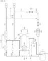
- FIG. 3 is a schematic diagram of a boil-off gas treatment system according to an expanded embodiment of the present invention. The following description will focus on differences from the basic embodiment.
- the boil-off gas treatment system differs from the boil-off gas treatment system according to the basic embodiment in terms of the configuration of a compressor that compresses boil-off gas.
- a first compressor 100A is configured as a multistage compressor including a plurality of compressors and compressing boil-off gas to a fuel supply pressure required for an onboard propulsion engine E1
- a second compressor 100B is configured as a compressor compressing boil-off gas to a fuel supply pressure required for a power generation engine E2, which is supplied with fuel at a lower pressure than the propulsion engine, such that the second compressor redundant to the first compressor compresses boil-off gas to a different pressure than the first compressor.
- the first compressor 100A may compress boil-off gas generated in the storage tank to a fuel supply pressure required for the propulsion engine E1 through the plurality of compressors and an intermediate cooler and supply the compressed boil-off gas as fuel to the propulsion engine E1.
- the power generation engine E2 may be supplied with boil-off gas compressed while passing through part of the first compressor or boil-off gas compressed by the second compressor.
- the boil-off gas compressed while passing through part of the first compressor may be supplied to a heat exchanger to be cooled.
- either the first compressor or the second compressor may be selectively operated depending on the operation condition of the ship.
- the first compressor 100A When the engines of the ship consume a large amount of fuel, such as when the ship is underway, the first compressor 100A is operated. Boil-off gas generated in the storage tank T is supplied to the heat exchanger 200 along the boil-off gas supply line GL and is then sent to the first compressor 100A along a first line GLA to be compressed.
- boil-off gas compressed while passing through the entirety of the first compressor 100A is supplied as fuel to the propulsion engine E1 along the first fuel supply line FL1
- boil-off gas compressed while passing through the front compression section 110 of the first compressor is supplied as fuel to the power generation engine E2 along the second fuel supply line FL2.
- Surplus compressed gas in excess of what is needed for the propulsion engine and the power generation engine is supplied to the heat exchanger 200 along the reliquefaction line RL, cooled through heat exchange with a refrigerant circulated along a refrigerant circulation line NL and uncompressed boil-off gas, reliquefied through a decompressor 400 and a gas-liquid separator 500, and returned to the storage tank T.
- the reliquefaction system may not be operated, or boil-off gas in the storage tank may be supplied directly to the first compressor along a branch line BL without passing through the heat exchanger.
- a multistage high-pressure compressor capable of supplying boil-off gas as fuel to a propulsion engine and a compressor capable of compressing boil-off gas to a pressure required for a power generation engine having a lower fuel supply pressure than the propulsion engine are provided to be selectively operated depending on the operation condition of a ship, consumption of electrical energy required for fuel supply and reliquefaction can be reduced through utilization of boil-off gas as fuel while meeting redundancy requirements, thereby ensuring efficient operation of the ship.
- the cooling efficiency and reliquefaction rate of the heat exchanger can be enhanced through utilization of cold heat from boil-off gas itself and cold heat in the refrigerant cycle and reliquefaction can be performed with respect to only boil-off gas remaining after boil-off gas generated in the storage tank is consumed as fuel, the load of the refrigerant cycle can be reduced while reducing consumption of liquefied gas as fuel.
Landscapes
- Engineering & Computer Science (AREA)
- Mechanical Engineering (AREA)
- Chemical & Material Sciences (AREA)
- Combustion & Propulsion (AREA)
- General Engineering & Computer Science (AREA)
- Ocean & Marine Engineering (AREA)
- Chemical Kinetics & Catalysis (AREA)
- Oil, Petroleum & Natural Gas (AREA)
- General Chemical & Material Sciences (AREA)
- Health & Medical Sciences (AREA)
- Toxicology (AREA)
- Public Health (AREA)
- General Health & Medical Sciences (AREA)
- Environmental & Geological Engineering (AREA)
- Filling Or Discharging Of Gas Storage Vessels (AREA)
Applications Claiming Priority (2)
| Application Number | Priority Date | Filing Date | Title |
|---|---|---|---|
| KR1020210123382A KR102473952B1 (ko) | 2021-09-15 | 2021-09-15 | 선박의 증발가스 처리 시스템 및 방법 |
| PCT/KR2021/019887 WO2023042975A1 (ko) | 2021-09-15 | 2021-12-24 | 선박의 증발가스 처리 시스템 및 방법 |
Publications (2)
| Publication Number | Publication Date |
|---|---|
| EP4403452A1 true EP4403452A1 (de) | 2024-07-24 |
| EP4403452A4 EP4403452A4 (de) | 2025-09-03 |
Family
ID=84407316
Family Applications (1)
| Application Number | Title | Priority Date | Filing Date |
|---|---|---|---|
| EP21957641.0A Pending EP4403452A4 (de) | 2021-09-15 | 2021-12-24 | System und verfahren zur behandlung von boil-off-gas eines schiffs |
Country Status (6)
| Country | Link |
|---|---|
| US (1) | US20250136262A1 (de) |
| EP (1) | EP4403452A4 (de) |
| JP (1) | JP2024531581A (de) |
| KR (1) | KR102473952B1 (de) |
| CN (1) | CN117980225A (de) |
| WO (1) | WO2023042975A1 (de) |
Families Citing this family (4)
| Publication number | Priority date | Publication date | Assignee | Title |
|---|---|---|---|---|
| KR102728689B1 (ko) * | 2022-12-20 | 2024-11-12 | 한화오션 주식회사 | 선박의 증발가스 처리 시스템 |
| KR102728686B1 (ko) * | 2022-12-20 | 2024-11-12 | 한화오션 주식회사 | 선박의 증발가스 처리 시스템 및 방법 |
| JP2025009141A (ja) * | 2023-07-07 | 2025-01-20 | 川崎重工業株式会社 | 再液化装置 |
| CN117432930B (zh) * | 2023-12-07 | 2024-05-03 | 武汉齐达康能源装备有限公司 | 一种井口天然气混输快速增压装置及使用方法 |
Family Cites Families (11)
| Publication number | Priority date | Publication date | Assignee | Title |
|---|---|---|---|---|
| KR101386543B1 (ko) * | 2012-10-24 | 2014-04-18 | 대우조선해양 주식회사 | 선박의 증발가스 처리 시스템 |
| JP2016169837A (ja) * | 2015-03-13 | 2016-09-23 | 三井造船株式会社 | ボイルオフガス回収システム |
| KR101751854B1 (ko) * | 2015-11-12 | 2017-06-28 | 대우조선해양 주식회사 | 선박 |
| KR101982313B1 (ko) * | 2016-06-03 | 2019-05-24 | 현대중공업 주식회사 | 가스 처리 시스템 및 이를 포함하는 선박 |
| KR20170030508A (ko) * | 2017-03-10 | 2017-03-17 | 대우조선해양 주식회사 | 증발가스 재액화 시스템 및 방법 |
| JP2019011735A (ja) * | 2017-06-30 | 2019-01-24 | 三井E&S造船株式会社 | 液化ガス燃料供給システム |
| KR102003409B1 (ko) * | 2018-11-01 | 2019-07-24 | 대우조선해양 주식회사 | 선박용 증발가스 재액화 방법 및 시스템 |
| KR102183949B1 (ko) * | 2019-04-09 | 2020-11-30 | 대우조선해양 주식회사 | 선박의 증발가스 처리 시스템 및 방법 |
| KR102694834B1 (ko) * | 2019-05-22 | 2024-08-16 | 한화오션 주식회사 | 선박의 증발가스 처리 시스템 및 방법 |
| KR102770407B1 (ko) * | 2019-08-23 | 2025-02-24 | 한화오션 주식회사 | 선박의 증발가스 재액화 시스템 및 방법 |
| KR102253379B1 (ko) * | 2019-12-31 | 2021-05-21 | 대우조선해양 주식회사 | 선박의 증발가스 처리 시스템 및 방법 |
-
2021
- 2021-09-15 KR KR1020210123382A patent/KR102473952B1/ko active Active
- 2021-12-24 EP EP21957641.0A patent/EP4403452A4/de active Pending
- 2021-12-24 US US18/691,301 patent/US20250136262A1/en active Pending
- 2021-12-24 CN CN202180102374.2A patent/CN117980225A/zh active Pending
- 2021-12-24 WO PCT/KR2021/019887 patent/WO2023042975A1/ko not_active Ceased
- 2021-12-24 JP JP2024514548A patent/JP2024531581A/ja active Pending
Also Published As
| Publication number | Publication date |
|---|---|
| CN117980225A (zh) | 2024-05-03 |
| JP2024531581A (ja) | 2024-08-29 |
| EP4403452A4 (de) | 2025-09-03 |
| WO2023042975A1 (ko) | 2023-03-23 |
| US20250136262A1 (en) | 2025-05-01 |
| KR102473952B1 (ko) | 2022-12-06 |
Similar Documents
| Publication | Publication Date | Title |
|---|---|---|
| EP4403452A1 (de) | System und verfahren zur behandlung von boil-off-gas eines schiffs | |
| KR20210023540A (ko) | 선박의 증발가스 재액화 시스템 및 방법 | |
| KR102033538B1 (ko) | 선박의 증발가스 재액화 시스템 및 방법 | |
| KR102370607B1 (ko) | 선박의 증발가스 재액화 시스템 및 방법 | |
| KR102460402B1 (ko) | 전력 절감형 액화가스 연료 선박 및 상기 액화가스 연료 선박의 증발가스 처리 방법 | |
| KR102370609B1 (ko) | 선박의 증발가스 재액화 시스템 및 방법 | |
| KR102276356B1 (ko) | 선박의 증발가스 처리 시스템 및 방법 | |
| KR102361515B1 (ko) | 선박의 증발가스 처리 시스템 및 방법 | |
| KR102203736B1 (ko) | 선박의 증발가스 처리 시스템 및 방법 | |
| KR102203743B1 (ko) | 선박의 증발가스 처리 시스템 및 방법 | |
| JPWO2023042975A5 (de) | ||
| KR102516755B1 (ko) | 선박의 증발가스 재액화 시스템 및 방법 | |
| KR20200125374A (ko) | 선박의 증발가스 재액화 시스템 및 방법 | |
| KR102203737B1 (ko) | 선박의 증발가스 처리 시스템 및 방법 | |
| KR102183948B1 (ko) | 선박의 증발가스 재액화 시스템 및 방법 | |
| KR102185816B1 (ko) | 선박의 증발가스 처리 시스템 및 방법 | |
| KR102729237B1 (ko) | 선박의 증발가스 처리 시스템 및 방법 | |
| KR102397726B1 (ko) | 선박의 증발가스 처리 시스템 및 방법 | |
| KR102185815B1 (ko) | 선박의 증발가스 처리 시스템 및 방법 | |
| KR102150461B1 (ko) | 선박의 증발가스 처리 시스템 및 방법 | |
| KR102176544B1 (ko) | 선박의 증발가스 처리 시스템 및 방법 | |
| KR102291927B1 (ko) | 선박의 증발가스 처리 시스템 및 방법 | |
| KR20240133897A (ko) | 선박의 증발가스 처리 시스템 및 방법 | |
| KR102538934B1 (ko) | 선박용 증발가스 재액화 시스템 및 방법 | |
| KR20240129652A (ko) | 선박의 증발가스 처리 시스템 및 방법 |
Legal Events
| Date | Code | Title | Description |
|---|---|---|---|
| STAA | Information on the status of an ep patent application or granted ep patent |
Free format text: STATUS: THE INTERNATIONAL PUBLICATION HAS BEEN MADE |
|
| PUAI | Public reference made under article 153(3) epc to a published international application that has entered the european phase |
Free format text: ORIGINAL CODE: 0009012 |
|
| STAA | Information on the status of an ep patent application or granted ep patent |
Free format text: STATUS: REQUEST FOR EXAMINATION WAS MADE |
|
| 17P | Request for examination filed |
Effective date: 20240412 |
|
| AK | Designated contracting states |
Kind code of ref document: A1 Designated state(s): AL AT BE BG CH CY CZ DE DK EE ES FI FR GB GR HR HU IE IS IT LI LT LU LV MC MK MT NL NO PL PT RO RS SE SI SK SM TR |
|
| DAV | Request for validation of the european patent (deleted) | ||
| DAX | Request for extension of the european patent (deleted) | ||
| A4 | Supplementary search report drawn up and despatched |
Effective date: 20250804 |
|
| RIC1 | Information provided on ipc code assigned before grant |
Ipc: B63B 25/16 20060101AFI20250729BHEP Ipc: B63H 21/38 20060101ALI20250729BHEP Ipc: B63B 17/00 20060101ALI20250729BHEP Ipc: F17C 9/02 20060101ALI20250729BHEP Ipc: F17C 6/00 20060101ALI20250729BHEP Ipc: F02M 21/02 20060101ALI20250729BHEP Ipc: F02M 25/08 20060101ALI20250729BHEP |