EP4403447A1 - Straddled vehicle - Google Patents
Straddled vehicle Download PDFInfo
- Publication number
- EP4403447A1 EP4403447A1 EP23215789.1A EP23215789A EP4403447A1 EP 4403447 A1 EP4403447 A1 EP 4403447A1 EP 23215789 A EP23215789 A EP 23215789A EP 4403447 A1 EP4403447 A1 EP 4403447A1
- Authority
- EP
- European Patent Office
- Prior art keywords
- cover
- vehicle
- windscreen
- transparent cover
- mounting portion
- Prior art date
- Legal status (The legal status is an assumption and is not a legal conclusion. Google has not performed a legal analysis and makes no representation as to the accuracy of the status listed.)
- Granted
Links
Images






Classifications
-
- B—PERFORMING OPERATIONS; TRANSPORTING
- B62—LAND VEHICLES FOR TRAVELLING OTHERWISE THAN ON RAILS
- B62J—CYCLE SADDLES OR SEATS; AUXILIARY DEVICES OR ACCESSORIES SPECIALLY ADAPTED TO CYCLES AND NOT OTHERWISE PROVIDED FOR, e.g. ARTICLE CARRIERS OR CYCLE PROTECTORS
- B62J17/00—Weather guards for riders; Fairings or stream-lining parts not otherwise provided for
-
- B—PERFORMING OPERATIONS; TRANSPORTING
- B62—LAND VEHICLES FOR TRAVELLING OTHERWISE THAN ON RAILS
- B62J—CYCLE SADDLES OR SEATS; AUXILIARY DEVICES OR ACCESSORIES SPECIALLY ADAPTED TO CYCLES AND NOT OTHERWISE PROVIDED FOR, e.g. ARTICLE CARRIERS OR CYCLE PROTECTORS
- B62J17/00—Weather guards for riders; Fairings or stream-lining parts not otherwise provided for
- B62J17/02—Weather guards for riders; Fairings or stream-lining parts not otherwise provided for shielding only the rider's front
- B62J17/04—Windscreens
-
- B—PERFORMING OPERATIONS; TRANSPORTING
- B62—LAND VEHICLES FOR TRAVELLING OTHERWISE THAN ON RAILS
- B62J—CYCLE SADDLES OR SEATS; AUXILIARY DEVICES OR ACCESSORIES SPECIALLY ADAPTED TO CYCLES AND NOT OTHERWISE PROVIDED FOR, e.g. ARTICLE CARRIERS OR CYCLE PROTECTORS
- B62J45/00—Electrical equipment arrangements specially adapted for use as accessories on cycles, not otherwise provided for
- B62J45/40—Sensor arrangements; Mounting thereof
-
- B—PERFORMING OPERATIONS; TRANSPORTING
- B62—LAND VEHICLES FOR TRAVELLING OTHERWISE THAN ON RAILS
- B62J—CYCLE SADDLES OR SEATS; AUXILIARY DEVICES OR ACCESSORIES SPECIALLY ADAPTED TO CYCLES AND NOT OTHERWISE PROVIDED FOR, e.g. ARTICLE CARRIERS OR CYCLE PROTECTORS
- B62J45/00—Electrical equipment arrangements specially adapted for use as accessories on cycles, not otherwise provided for
- B62J45/40—Sensor arrangements; Mounting thereof
- B62J45/41—Sensor arrangements; Mounting thereof characterised by the type of sensor
-
- B—PERFORMING OPERATIONS; TRANSPORTING
- B62—LAND VEHICLES FOR TRAVELLING OTHERWISE THAN ON RAILS
- B62J—CYCLE SADDLES OR SEATS; AUXILIARY DEVICES OR ACCESSORIES SPECIALLY ADAPTED TO CYCLES AND NOT OTHERWISE PROVIDED FOR, e.g. ARTICLE CARRIERS OR CYCLE PROTECTORS
- B62J45/00—Electrical equipment arrangements specially adapted for use as accessories on cycles, not otherwise provided for
- B62J45/40—Sensor arrangements; Mounting thereof
- B62J45/42—Sensor arrangements; Mounting thereof characterised by mounting
-
- B—PERFORMING OPERATIONS; TRANSPORTING
- B62—LAND VEHICLES FOR TRAVELLING OTHERWISE THAN ON RAILS
- B62J—CYCLE SADDLES OR SEATS; AUXILIARY DEVICES OR ACCESSORIES SPECIALLY ADAPTED TO CYCLES AND NOT OTHERWISE PROVIDED FOR, e.g. ARTICLE CARRIERS OR CYCLE PROTECTORS
- B62J17/00—Weather guards for riders; Fairings or stream-lining parts not otherwise provided for
- B62J17/10—Ventilation or air guiding devices forming part of fairings
-
- B—PERFORMING OPERATIONS; TRANSPORTING
- B62—LAND VEHICLES FOR TRAVELLING OTHERWISE THAN ON RAILS
- B62J—CYCLE SADDLES OR SEATS; AUXILIARY DEVICES OR ACCESSORIES SPECIALLY ADAPTED TO CYCLES AND NOT OTHERWISE PROVIDED FOR, e.g. ARTICLE CARRIERS OR CYCLE PROTECTORS
- B62J27/00—Safety equipment
Definitions
- the present invention relates to a straddled vehicle.
- some straddled vehicles are provided with a sensing device for detecting a situation in front of the vehicle.
- a sensing device for detecting a situation in front of the vehicle.
- an imaging device is arranged behind the opening provided in the front cowl. It is also stated that the opening may be covered with a protective glass.
- An object of the present invention is provide a straddled vehicle having improved maintainability of a transparent cover and to deter theft or mischief of the transparent cover in a straddled vehicle provided with the transparent cover for protecting a sensing device. According to the present invention said object is solved by straddled vehicle having the features of independent claim 1. Preferred embodiments are laid down in the dependent claims.
- a straddled vehicle includes a vehicle body, a windscreen, a sensing device, and a transparent cover.
- the vehicle body includes a front cover.
- the windscreen is arranged above the front cover.
- the sensing device is arranged behind the front cover. The sensing device detects a situation in front of the vehicle body.
- the transparent cover is arranged in front of the sensing device.
- the transparent cover includes a first mounting portion detachably attached to the front cover. The windscreen overlaps the first mounting portion from above and/or from the front.
- the transparent cover is detachably attached to the front cover by the first mounting portion. Therefore, the maintainability of the transparent cover is improved. Moreover, the windscreen overlaps with the first mounting portion from above and/or from the front of the first mounting portion. Access to the first mounting portion is therefore restricted by the windscreen. Thereby, theft of the transparent cover or mischief is deterred.
- the windscreen may be attached to the vehicle body so as to be movable between a first position and a second position.
- the second position may be located above the first position.
- the windscreen may overlap the first mounting portion from above the first mounting portion when the windscreen is positioned at the first position.
- the first mounting portion may not overlap the first mounting portion from above the first mounting portion.
- access to the first mounting portion is obstructed by the windscreen. Thereby, theft or mischief to the transparent cover is deterred.
- the windscreen is positioned at the second position, access to the first attachment portion is possible.
- the front cover may include an outer cover and an inner cover. At least a portion of the inner cover may be arranged behind the outer cover.
- the engaging portion may be provided at the inner cover and may be arranged behind the outer cover. In this case, the engaging portion is protected by the outer cover.
- a first gap may be provided between the side edge of the transparent cover and the front cover. In this case, fogging of the transparent cover is suppressed by air entering through the first gap.
- a second gap may be provided between the guide portion and the sensing device.
- the first space may communicate with a second space inside the front cover through the second gap. In this case, fogging of the transparent cover is suppressed by air entering the first space in the guide portion through the second gap.
- a third gap may be provided between the guide portion and the transparent cover.
- the side edge of the transparent cover may have a bent shape to cover the third gap. In this case, the intrusion of water through the third gap is suppressed by the bent shape of the side edge of the transparent cover.
- a wind guide port may be provided between a lower end of the windscreen and the transparent cover. In this case, part of the traveling air flows from the wind guide port to the back side of the windscreen, thereby rectifying the turbulent air in the space above a rider's head.
- An upper surface of the transparent cover may have a downwardly recessed shape.
- the recessed shape of the transparent cover provides the wind guide port between the lower end of the windscreen and the transparent cover.
- FIG. 1 is a side view of a straddled vehicle 1 according to an embodiment.
- the straddled vehicle 1 according to the embodiment is a motorcycle.
- the straddled vehicle 1 includes a vehicle body 2, a steering device 3, a front wheel 4, and a rear wheel 5.
- the front, rear, left, and right directions refer to the front, rear, up, down, left, and right directions as seen from a rider sitting on the seat 8. Accordingly, it is referred to a front-rear-direction of the vehicle, an up-down-direction of the vehicle and a left-right-direction of the vehicle.
- the up-down-direction of the vehicle corresponds with the vertical direction.
- the steering device 3 is supported by the head pipe 11 so as to be rotatable to the left and right.
- the steering device 3 includes a front fork 12 and a handle member 13.
- the front fork 12 rotatably supports the front wheel 4.
- the handle member 13 is connected to the front fork 12.
- the rear wheel 5 is rotatably supported by the vehicle body frame 6 via a swing arm 14.
- the vehicle body 2 includes a front cover 15.
- the front cover 15 is arranged in front of the head pipe 11.
- the front cover 15 covers the head pipe 11 from the front.
- the vehicle body 2 includes a windscreen 16.
- the windscreen 16 is arranged above the front cover 15.
- the windscreen 16 is attached to the front cover 15.
- FIG. 2 is a front view of the front cover 15.
- the straddled vehicle 1 includes a left light 21 and a right light 22.
- the left light 21 and the right light 22 are, for example, position lights.
- the left light 21 and the right light 22 may be headlights.
- the front cover 15 includes an opening 23.
- the opening 23 is arranged below the windscreen 16.
- the straddled vehicle 1 includes a sensing device 24.
- the sensing device 24 detects a situation in front of the vehicle body 2.
- the sensing device 24 is, for example, a camera, and photographs the front of the vehicle body 2 to generate image data showing the front of the vehicle body 2.
- the sensing device 24 is arranged behind the front cover 15.
- the sensing device 24 is arranged behind the opening 23.
- the sensing device 24 overlaps the opening 23 as seen from the vehicle front view.
- a transparent cover 25 for protecting the sensing device 24 is arranged in the opening 23.
- the transparent cover 25 is made of transparent resin, for example. Alternatively, the transparent cover 25 may be made of transparent glass.
- the transparent cover 25 is arranged in front of the sensing device 24.
- the opening 23 is closed by the transparent cover 25.
- the front cover 15 includes an outer cover 17 and an inner cover 18.
- the left light 21 and the right light 22 are arranged on the outer cover 17.
- the opening 23 is provided at the outer cover 17.
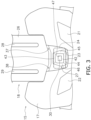
- FIG. 3 is a front view of the front cover 15 with the windscreen 16 and the transparent cover 25 omitted. As shown in FIG. 3 , an upper portion of the inner cover 18 protrudes upward from the outer cover 17.
- the inner cover 18 includes a screen support portion 26. The screen support portion 26 extends upward from the outer cover 17.
- the inner cover 18 includes a guide portion 27.
- the guide portion 27 is arranged below the screen support portion 26.
- the guide portion 27 is arranged behind the opening 23.
- the guide portion 27 is arranged between the transparent cover 25 and the sensing device 24. The guide portion 27 will be described later in detail.
- the windscreen 16 is supported by the screen support portion 26 via a movable member 19. Specifically, the windscreen 16 is attached to the movable member 19. The movable member 19 is supported by the screen support portion 26 via sliders 28 and 29. The movable member 19 is movably supported in the vertical direction with respect to the screen support portion 26. The windscreen 16 is thereby mounted on the vehicle body 2 so as to be movable between a first position and a second position. The second position is located above the first position.
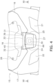
- FIG. 4 is a front view of the front cover 15 when the windscreen 16 is positioned at the first position.
- FIG. 5 is a side sectional view of the front cover 15 when the windscreen 16 is positioned at the first position.
- FIG. 6 is a front view of the front cover 15 when the windscreen 16 is positioned at the second position.
- FIG. 7 is a side sectional view of the front cover 15 when the windscreen 16 is positioned at the second position.
- the transparent cover 25 includes first mounting portions 31 and 32 detachably attached to the front cover 15.
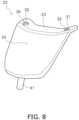
- FIG.8 is a perspective view of the transparent cover 25.
- the transparent cover 25 includes an upper surface 33 and a front surface 34.
- the transparent cover 25 has a bent shape between the upper surface 33 and the front surface 34.
- the upper surface 33 has a shape in which the center in the left-right direction is recessed downward.
- FIG. 9 is an enlarged side sectional view of the front cover 15.
- the transparent cover 25 includes a second mounting portion 41.
- the second mounting portion 41 is provided at a bottom of the transparent cover 25.
- the second mounting portion 41 protrudes downward from a lower edge of the front surface 34.
- the second mounting portion 41 is detachably attached to the front cover 15 by fitting.
- FIG. 13 is an enlarged sectional view of the front cover 15 and the transparent cover 25.
- third gaps G3a and G3b are provided between the guide portion 27 and the transparent cover 25.
- the guide portion 27 includes a first edge 48 and a second edge 49.
- the first edge 48 is connected to the left side surface 45.
- the first edge 48 extends leftward from the left side surface 45.
- the first edge 48 is arranged to face the inner surface of the transparent cover 25 from behind the transparent cover 25.
- the second edge 49 is connected to the right side surface 46.
- the second edge 49 extends rightward from the right side surface 46.
- the second edge 49 is arranged to face the inner surface of the transparent cover 25 from behind the transparent cover 25.
- the third gap G3a is provided between the first edge 48 and the inner surface of the transparent cover 25.
- the third gap G3a is narrower than the first gap G1a.
- the left side edge 61 of the transparent cover 25 has a bent shape to cover the third gap G3a.
- the transparent cover 25 includes a first bent portion 51.
- the first bent portion 51 is bent rearward from the left side edge 61 of the transparent cover 25.
- the first bent portion 51 covers the third gap G3a from the left side.
- the third gap G3b is provided between the second edge 49 and the inner surface of the transparent cover 25.
- the third gap G3b is narrower than the first gap G1b.
- the right side edge 63 of the transparent cover 25 has a bent shape to cover the third gap G3b.
- the transparent cover 25 includes a second bent portion 52.
- the second bent portion 52 is bent rearward from the right side edge 63 of the transparent cover 25.
- the second bent portion 52 covers the third gap G3b from the right side. Intrusion of water through the third gaps G3a and G3b is suppressed by the bent shape of the left and right side edges 61 and 63of the transparent cover 25.
- the lower end 65 of the windscreen 16 is arranged with a gap from the transparent cover 25. Accordingly, a wind guide port 66 is provided between the lower end 65 of the windscreen 16 and the transparent cover 25. Further, as described above, the upper surface 33 of the transparent cover 25 has a downward recessed shape. Thereby, the space behind the windscreen 16 is expanded. When the straddled vehicle 1 is running, part of the running wind flows from the wind guide port 66 to the back side of the windscreen 16, thereby rectifying the turbulent flow in the space above a rider's head.
- the transparent cover 25 is detachably attached to the front cover 15 by the first mounting portions 31 and 32. Therefore, the maintainability of the transparent cover 25 is improved. Moreover, the windscreen 16 overlaps the first mounting portions 31 and 32 from above and from the front of the first mounting portions 31 and 32. Therefore, access to the first mounting portions 31 and 32 is restricted by the windscreen 16. Thereby, theft of the transparent cover 25 or mischief is deterred.
- the windscreen 16 may overlap the first mounting portions 31 and 32 only from above the first mounting portions 31 and 32.
- the windscreen 16 may overlap the first mounting portions 31 and 32 only from the front of the first mounting portions 31 and 32.
- the structures of the first mounting portions 31 and 32 are not limited to those of the above embodiment, and may be modified.
- the first mounting portions 31 and 32 may be arranged at a position other than the upper surface 33 of the transparent cover 25.
- the structure of the second mounting portion 41 is not limited to that of the above embodiment, and may be modified.
- the second mounting portion 41 may be attached by a fixing means such as a screw.
- the shape of the transparent cover 25 is not limited to that of the above embodiment, and may be changed.
- the upper surface 33 of transparent cover 25 may be flat.
- the structure of the guide portion 27 is not limited to that of the above embodiment, and may be modified.
- the guide portion 27 may be a separate body from the inner cover 18.
- the guide portion 27 may be omitted.
- the positions of the first gaps G1a and G1b may be changed.
- the position of the second gap G2 may be changed.
- the positions of the third gaps G3a and G3b may be changed.
- one or some of the first to third gaps G1a, G1b, G2, G3a, and G3b may be omitted.
Landscapes
- Engineering & Computer Science (AREA)
- Mechanical Engineering (AREA)
- Fittings On The Vehicle Exterior For Carrying Loads, And Devices For Holding Or Mounting Articles (AREA)
Abstract
Description
- The present invention relates to a straddled vehicle.
- Conventionally, some straddled vehicles are provided with a sensing device for detecting a situation in front of the vehicle. For example, in the straddled vehicle disclosed in
WO 2019/180941 A , an imaging device is arranged behind the opening provided in the front cowl. It is also stated that the opening may be covered with a protective glass. - As in the straddled vehicle described above, the sensing device is protected from stepping stones, insects, dust, or the like by covering the sensing device with a transparent cover such as a protective glass. However, if the transparent cover is damaged by stepping stones, or if dirt adheres to the transparent cover due to insects, dust, or the like, the detection capability of the sensing device may deteriorate. In addition, fogging of the transparent cover may also reduce the detection capability of the sensing device.
- In the above case, the dirt or fog can be easily removed by making the transparent cover detachable. Alternatively, the transparent cover can be easily replaced. However, in that case, there is concern about theft of the transparent cover or mischief. An object of the present invention is provide a straddled vehicle having improved maintainability of a transparent cover and to deter theft or mischief of the transparent cover in a straddled vehicle provided with the transparent cover for protecting a sensing device. According to the present invention said object is solved by straddled vehicle having the features of
independent claim 1. Preferred embodiments are laid down in the dependent claims. - A straddled vehicle according to one aspect includes a vehicle body, a windscreen, a sensing device, and a transparent cover. The vehicle body includes a front cover. The windscreen is arranged above the front cover. The sensing device is arranged behind the front cover. The sensing device detects a situation in front of the vehicle body. The transparent cover is arranged in front of the sensing device. The transparent cover includes a first mounting portion detachably attached to the front cover. The windscreen overlaps the first mounting portion from above and/or from the front.
- In the straddled vehicle according to the present aspect, the transparent cover is detachably attached to the front cover by the first mounting portion. Therefore, the maintainability of the transparent cover is improved. Moreover, the windscreen overlaps with the first mounting portion from above and/or from the front of the first mounting portion. Access to the first mounting portion is therefore restricted by the windscreen. Thereby, theft of the transparent cover or mischief is deterred.
- The windscreen may be attached to the vehicle body so as to be movable between a first position and a second position. The second position may be located above the first position. The windscreen may overlap the first mounting portion from above the first mounting portion when the windscreen is positioned at the first position. When the windscreen is positioned at the second position, the first mounting portion may not overlap the first mounting portion from above the first mounting portion. In this case, when the windscreen is positioned at the first position, access to the first mounting portion is obstructed by the windscreen. Thereby, theft or mischief to the transparent cover is deterred. When the windscreen is positioned at the second position, access to the first attachment portion is possible.
- The windscreen may overlap the first mounting portion from the front of the first mounting portion when the windscreen is positioned at the first position. When the windscreen is positioned at the second position, the windscreen may not overlap the first mounting portion from the front of the first mounting portion. In this case, when the windscreen is positioned at the first position, access to the first mounting portion is obstructed by the windscreen. Thereby, theft or mischief to the transparent cover is deterred. When the windscreen is positioned at the second position, access to the first attachment is possible.
- The first mounting portion may be arranged on an upper surface of the transparent cover. In this case, ease of access to the first mounting portion improves maintainability.
- The transparent cover may include a second mounting portion provided at a bottom of the transparent cover. The second mounting portion may be detachably attached to the front cover by fitting. In this case, the attachment and detachment of the transparent cover becomes easier.
- The front cover may include an engaging portion to which the second mounting portion is attached. The engaging portion may support the second mounting portion such that the transparent cover is rotatable about the second mounting portion. In this case, the transparent cover can be easily removed from the front cover by rotating the transparent cover.
- The front cover may include an outer cover and an inner cover. At least a portion of the inner cover may be arranged behind the outer cover. The engaging portion may be provided at the inner cover and may be arranged behind the outer cover. In this case, the engaging portion is protected by the outer cover.
- A first gap may be provided between the side edge of the transparent cover and the front cover. In this case, fogging of the transparent cover is suppressed by air entering through the first gap.
- The front cover may include a guide portion arranged between the transparent cover and the sensing device. The guide portion may cover a periphery of a first space between the transparent cover and the sensing device. In this case, even if water enters through the first gap, the guide portion prevents water from adhering to the sensing device or the rear surface of the transparent cover.
- A second gap may be provided between the guide portion and the sensing device. The first space may communicate with a second space inside the front cover through the second gap. In this case, fogging of the transparent cover is suppressed by air entering the first space in the guide portion through the second gap.
- A third gap may be provided between the guide portion and the transparent cover. The side edge of the transparent cover may have a bent shape to cover the third gap. In this case, the intrusion of water through the third gap is suppressed by the bent shape of the side edge of the transparent cover.
- A wind guide port may be provided between a lower end of the windscreen and the transparent cover. In this case, part of the traveling air flows from the wind guide port to the back side of the windscreen, thereby rectifying the turbulent air in the space above a rider's head.
- An upper surface of the transparent cover may have a downwardly recessed shape. In this case, the recessed shape of the transparent cover provides the wind guide port between the lower end of the windscreen and the transparent cover.
-
-
FIG. 1 is a side view of a straddled vehicle according to an embodiment. -
FIG. 2 is a front view of a front cover. -
FIG. 3 is a front view of the front cover with a windscreen and a transparent cover omitted. -
FIG. 4 is a front view of the front cover when the windscreen is positioned at a first position. -
FIG. 5 is a side sectional view of the front cover when the windscreen is positioned at the first position. -
FIG. 6 is a front view of the front cover when the windscreen is positioned at a second position. -
FIG. 7 is a side sectional view of the front cover when the windscreen is positioned at the second position. -
FIG. 8 is a perspective view of the transparent cover. -
FIG. 9 is an enlarged side sectional view of the front cover. -
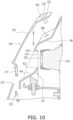
FIG. 10 is an enlarged side sectional view of the front cover. -
FIG. 11 is an enlarged side sectional view of the front cover. -
FIG. 12 is a cross-sectional view taken along the line XII-XII inFIG. 4 . -
FIG. 13 is an enlarged sectional view of the front cover and the transparent cover. - A straddled vehicle according to an embodiment will be described below with reference to the drawings.
FIG. 1 is a side view of a straddledvehicle 1 according to an embodiment. The straddledvehicle 1 according to the embodiment is a motorcycle. As shown inFIG. 1 , the straddledvehicle 1 includes avehicle body 2, asteering device 3, a front wheel 4, and arear wheel 5. In the following description, the front, rear, left, and right directions refer to the front, rear, up, down, left, and right directions as seen from a rider sitting on the seat 8. Accordingly, it is referred to a front-rear-direction of the vehicle, an up-down-direction of the vehicle and a left-right-direction of the vehicle. The up-down-direction of the vehicle corresponds with the vertical direction. - The
vehicle body 2 includes a vehicle body frame 6, apower unit 7, and a seat 8. The vehicle body frame 6 includes ahead pipe 11. Thepower unit 7 includes, for example, an internal combustion engine. Alternatively, thepower unit 7 may include an electric motor. - The
steering device 3 is supported by thehead pipe 11 so as to be rotatable to the left and right. Thesteering device 3 includes afront fork 12 and ahandle member 13. Thefront fork 12 rotatably supports the front wheel 4. Thehandle member 13 is connected to thefront fork 12. Therear wheel 5 is rotatably supported by the vehicle body frame 6 via aswing arm 14. - The
vehicle body 2 includes afront cover 15. Thefront cover 15 is arranged in front of thehead pipe 11. Thefront cover 15 covers thehead pipe 11 from the front. Thevehicle body 2 includes awindscreen 16. Thewindscreen 16 is arranged above thefront cover 15. Thewindscreen 16 is attached to thefront cover 15. -
FIG. 2 is a front view of thefront cover 15. As shown inFIG. 2 , the straddledvehicle 1 includes aleft light 21 and aright light 22. Theleft light 21 and theright light 22 are, for example, position lights. Alternatively, theleft light 21 and theright light 22 may be headlights. Thefront cover 15 includes anopening 23. Theopening 23 is arranged below thewindscreen 16. - The straddled
vehicle 1 includes asensing device 24. Thesensing device 24 detects a situation in front of thevehicle body 2. Thesensing device 24 is, for example, a camera, and photographs the front of thevehicle body 2 to generate image data showing the front of thevehicle body 2. Thesensing device 24 is arranged behind thefront cover 15. Thesensing device 24 is arranged behind theopening 23. Thesensing device 24 overlaps theopening 23 as seen from the vehicle front view. Atransparent cover 25 for protecting thesensing device 24 is arranged in theopening 23. Thetransparent cover 25 is made of transparent resin, for example. Alternatively, thetransparent cover 25 may be made of transparent glass. Thetransparent cover 25 is arranged in front of thesensing device 24. Theopening 23 is closed by thetransparent cover 25. - The
front cover 15 includes anouter cover 17 and aninner cover 18. Theleft light 21 and theright light 22 are arranged on theouter cover 17. Theopening 23 is provided at theouter cover 17.FIG. 3 is a front view of thefront cover 15 with thewindscreen 16 and thetransparent cover 25 omitted. As shown inFIG. 3 , an upper portion of theinner cover 18 protrudes upward from theouter cover 17. Theinner cover 18 includes ascreen support portion 26. Thescreen support portion 26 extends upward from theouter cover 17. - The
inner cover 18 includes aguide portion 27. Theguide portion 27 is arranged below thescreen support portion 26. Theguide portion 27 is arranged behind theopening 23. Theguide portion 27 is arranged between thetransparent cover 25 and thesensing device 24. Theguide portion 27 will be described later in detail. - As shown in
FIG. 2 , thewindscreen 16 is supported by thescreen support portion 26 via amovable member 19. Specifically, thewindscreen 16 is attached to themovable member 19. Themovable member 19 is supported by thescreen support portion 26 viasliders movable member 19 is movably supported in the vertical direction with respect to thescreen support portion 26. Thewindscreen 16 is thereby mounted on thevehicle body 2 so as to be movable between a first position and a second position. The second position is located above the first position. -
FIG. 4 is a front view of thefront cover 15 when thewindscreen 16 is positioned at the first position.FIG. 5 is a side sectional view of thefront cover 15 when thewindscreen 16 is positioned at the first position.FIG. 6 is a front view of thefront cover 15 when thewindscreen 16 is positioned at the second position.FIG. 7 is a side sectional view of thefront cover 15 when thewindscreen 16 is positioned at the second position. - As shown in
FIGS. 4 and6 , thetransparent cover 25 includes first mountingportions front cover 15.FIG.8 is a perspective view of thetransparent cover 25. As shown inFIG. 8 , thetransparent cover 25 includes anupper surface 33 and afront surface 34. Thetransparent cover 25 has a bent shape between theupper surface 33 and thefront surface 34. Theupper surface 33 has a shape in which the center in the left-right direction is recessed downward. - The first mounting
portions upper surface 33 of thetransparent cover 25. The first mountingportions holes holes FIG. 3 , theinner cover 18 includesholes Screws transparent cover 25 to theinner cover 18 are passed through theholes portions holes inner cover 18, respectively. Thescrews holes portions - As shown in
FIGS. 4 and5 , thewindscreen 16 is positioned forward of the first mountingportions windscreen 16 is positioned at the first position. Further, when thewindscreen 16 is positioned at the first position, thewindscreen 16 is positioned below the first mountingportions windscreen 16 is positioned at the first position, thewindscreen 16 overlaps the first mountingportions portions windscreen 16 is positioned at the first position, thewindscreen 16 overlaps the first mountingportions portions windscreen 16 is positioned in the first position, thewindscreen 16 is positioned above thesensing device 24. - As shown in
FIGS. 6 and7 , thewindscreen 16 is positioned rearward of the first mountingportions windscreen 16 is positioned at the second position. Further, when thewindscreen 16 is positioned at the second position, thewindscreen 16 is positioned above the first mountingportions windscreen 16 is positioned at the second position, thewindscreen 16 does not overlap the first mountingportions portions windscreen 16 is positioned at the second position, thewindscreen 16 does not overlap the first mountingportions portions -
FIG. 9 is an enlarged side sectional view of thefront cover 15. As shown inFIGS. 8 and9 , thetransparent cover 25 includes a second mountingportion 41. The second mountingportion 41 is provided at a bottom of thetransparent cover 25. The second mountingportion 41 protrudes downward from a lower edge of thefront surface 34. The second mountingportion 41 is detachably attached to thefront cover 15 by fitting. - Specifically, the second mounting
portion 41 is detachably attached to theinner cover 18 by fitting. Theinner cover 18 includes an engagingportion 53. The engagingportion 53 is arranged behind theouter cover 17. Theouter cover 17 covers the engagingportion 53 from the front. The second mountingportion 41 is detachably attached to the engagingportion 53. The engagingportion 53 includes agroove 54. The second mountingportion 41 is engaged to the engagingportion 53 by being inserted into thegroove 54 of the engagingportion 53. As shown inFIG. 10 , when thewindscreen 16 is positioned at the second position, the second mountingportion 41 can be attached to and detached from the engagingportion 53 in the vertical direction. - As shown in
FIG. 9 , a gap G4 is provided between a lower edge of theopening 23 of theouter cover 17 and thetransparent cover 25. Further, the engagingportion 53 supports the second mountingportion 41 so that thetransparent cover 25 is rotatable around the second mountingportion 41. Therefore, as shown inFIG. 11 , when thewindscreen 16 is positioned at the second position, thetransparent cover 25 is rotatable around the second mountingportion 41 without being interfered by theouter cover 17. As a result, the degree of freedom of work when attaching and detaching thetransparent cover 25 is improved. -
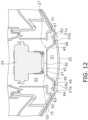
FIG. 12 is a cross-sectional view taken along the line XII-XII inFIG. 4 . As shown inFIG. 12 , thetransparent cover 25 is arranged in front of theguide portion 27. As shown inFIGS. 3 and12 , theguide portion 27 includes arear surface 42, anupper surface 43, abottom surface 44, aleft side surface 45, and aright side surface 46. Therear surface 42 is arranged to face thesensing device 24. Therear surface 42 includes anopening 47. Thesensing device 24 includes alens 30. Theopening 47 is arranged to face thelens 30. - The
upper surface 43, thebottom surface 44, theleft side surface 45, and theright side surface 46 extend forward from therear surface 42. As shown inFIG. 5 , theupper surface 43 and thebottom surface 44 are inclined forward so that a distance between theupper surface 43 and thebottom surface 44 widens in the vertical direction. Theupper surface 43 is inclined forward and upward. Thebottom surface 44 is inclined forward and downward. As shown inFIG. 12 , theleft side surface 45 and theright side surface 46 are inclined forward so that a distance between theleft side surface 45 and theright side surface 46 widens in the left-right direction. Theleft side surface 45 is inclined forward and leftward. Theright side surface 46 is inclined forward and rightward. - As shown in
FIG. 12 , a first space S1 and a second space S2 are provided inside thefront cover 15. The first space S1 is provided between thetransparent cover 25 and thesensing device 24. Theguide portion 27 covers the periphery of the first space S1. The first space S1 is separated from the second space S2 by theguide portion 27. Thesensing device 24 is arranged in the second space S2. - Between the side edges of the
transparent cover 25 and thefront cover 15, first gaps G1a and G1b are provided. Specifically, the first gap G1a is provided between theleft side edge 61 of thetransparent cover 25 and theleft side edge 62 of theopening 23. The first gap G1b is provided between theright side edge 63 of thetransparent cover 25 and theright side edge 64 of theopening 23. Air entering the second space S2 through the first gaps G1a and G1b prevents thetransparent cover 25 from fogging up. Further, even if water enters from the first gaps G1a and G1b, theguide portion 27 prevents the water from adhering to thesensing device 24 or the rear surface of thetransparent cover 25. - A second gap G2 is provided between the
guide portion 27 and thesensing device 24. Specifically, therear surface 42 of theguide portion 27 is positioned with the second gap G2 from thelens 30 of thesensing device 24. The first space S1 communicates with the second space S2 through the second gap G2. Air enters the first space S1 through the second gap G2, thereby suppressing fogging of thetransparent cover 25. -
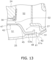
FIG. 13 is an enlarged sectional view of thefront cover 15 and thetransparent cover 25. As shown inFIG. 13 , third gaps G3a and G3b are provided between theguide portion 27 and thetransparent cover 25. Specifically, as shown inFIGS. 12 and13 , theguide portion 27 includes afirst edge 48 and asecond edge 49. Thefirst edge 48 is connected to theleft side surface 45. Thefirst edge 48 extends leftward from theleft side surface 45. Thefirst edge 48 is arranged to face the inner surface of thetransparent cover 25 from behind thetransparent cover 25. Thesecond edge 49 is connected to theright side surface 46. Thesecond edge 49 extends rightward from theright side surface 46. Thesecond edge 49 is arranged to face the inner surface of thetransparent cover 25 from behind thetransparent cover 25. - As shown in
FIG. 13 , the third gap G3a is provided between thefirst edge 48 and the inner surface of thetransparent cover 25. The third gap G3a is narrower than the first gap G1a. Theleft side edge 61 of thetransparent cover 25 has a bent shape to cover the third gap G3a. Specifically, thetransparent cover 25 includes a firstbent portion 51. The firstbent portion 51 is bent rearward from theleft side edge 61 of thetransparent cover 25. The firstbent portion 51 covers the third gap G3a from the left side. - The third gap G3b is provided between the
second edge 49 and the inner surface of thetransparent cover 25. The third gap G3b is narrower than the first gap G1b. Theright side edge 63 of thetransparent cover 25 has a bent shape to cover the third gap G3b. Specifically, thetransparent cover 25 includes a secondbent portion 52. The secondbent portion 52 is bent rearward from theright side edge 63 of thetransparent cover 25. The secondbent portion 52 covers the third gap G3b from the right side. Intrusion of water through the third gaps G3a and G3b is suppressed by the bent shape of the left and right side edges 61 and 63of thetransparent cover 25. - As shown in
FIG. 5 , thelower end 65 of thewindscreen 16 is arranged with a gap from thetransparent cover 25. Accordingly, awind guide port 66 is provided between thelower end 65 of thewindscreen 16 and thetransparent cover 25. Further, as described above, theupper surface 33 of thetransparent cover 25 has a downward recessed shape. Thereby, the space behind thewindscreen 16 is expanded. When the straddledvehicle 1 is running, part of the running wind flows from thewind guide port 66 to the back side of thewindscreen 16, thereby rectifying the turbulent flow in the space above a rider's head. - In the straddled
vehicle 1 according to the present embodiment described above, thetransparent cover 25 is detachably attached to thefront cover 15 by the first mountingportions transparent cover 25 is improved. Moreover, thewindscreen 16 overlaps the first mountingportions portions portions windscreen 16. Thereby, theft of thetransparent cover 25 or mischief is deterred. - According to a further embodiment, the
windscreen 16 may overlap the first mountingportions portions windscreen 16 may overlap the first mountingportions portions portions portions upper surface 33 of thetransparent cover 25. The structure of the second mountingportion 41 is not limited to that of the above embodiment, and may be modified. For example, the second mountingportion 41 may be attached by a fixing means such as a screw. - The shape of the
transparent cover 25 is not limited to that of the above embodiment, and may be changed. For example, theupper surface 33 oftransparent cover 25 may be flat. The structure of theguide portion 27 is not limited to that of the above embodiment, and may be modified. For example, theguide portion 27 may be a separate body from theinner cover 18. Alternatively, theguide portion 27 may be omitted. The positions of the first gaps G1a and G1b may be changed. The position of the second gap G2 may be changed. The positions of the third gaps G3a and G3b may be changed. Alternatively, one or some of the first to third gaps G1a, G1b, G2, G3a, and G3b may be omitted. - 2: Vehicle body, 15: Front cover, 16: Windscreen, 17: Outer cover, 18: Inner cover, 24: Sensing device, 25: Transparent cover, 27:
Guide portion 31, 32: First mounting portion, 41: Second mounting portion, 53: Engaging portion, 66: Wind guide port, G1a, G1b: First gap, G2: Second gap, G3a, G3b: Third gap, S1: First space, S2: Second space
Claims (13)
- A straddled vehicle (1) comprising:a vehicle body (2) including a front cover (15);a windscreen (16) arranged above the front cover (15) with regard to an up-down-direction of the vehicle;a sensing device (24) arranged behind the front cover (15) with regard to a front-rear-direction of the vehicle and configured to detect a situation in front of the vehicle body (2); anda transparent cover (25) arranged in front of the sensing device (24) with regard to the front-rear-direction of the vehicle, whereinthe transparent cover (25) includes a first mounting portion (31, 32) detachably mounted to the front cover (15), andthe windscreen (16) overlaps with the first mounting portion (31, 32) from above with regard to the up-down-direction of the vehicle and/or from a front of the first mounting portion (31, 32) with regard to the front-rear-direction of the vehicle.
- The straddled vehicle (1) according to claim 1, wherein the windscreen (16) is attached to the vehicle body (2) so as to be movable between a first position and a second position located above the first position above with regard to the up-down-direction of the vehicle.
- The straddled vehicle (1) according to claim 2, wherein the windscreen (16) overlaps the first mounting portion (31, 32) from above the first mounting portion (31, 32) with regard to the up-down-direction of the vehicle when the windscreen (16) is positioned at the first position, andthe first mounting portion (31, 32) does not overlap the first mounting portion (31, 32) from above the first mounting portion (31, 32) with regard to the up-down-direction of the vehicle when the windscreen (16) is positioned at the second position, and/orthe windscreen (16) overlaps the first mounting portion (31, 32) from the front of the first mounting portion (31, 32) with regard to the front-rear-direction of the vehicle when the windscreen (16) is positioned at the first position, andthe windscreen (16) does not overlap the first mounting portion (31, 32) from the front of the first mounting portion (31, 32) with regard to the front-rear-direction of the vehicle when the windscreen (16) is positioned at the second position.
- The straddled vehicle (1) according to any one of claims 1 to 3, wherein the first mounting portion (31, 32) is arranged on an upper surface (33) of the transparent cover (25) with regard to the up-down-direction of the vehicle.
- The straddled vehicle (1) according to any one of claims 1 to 4, wherein the transparent cover (25) includes a second mounting portion (41) provided at a bottom of the transparent cover (25) with regard to the up-down-direction of the vehicle, and the second mounting portion (41) is detachably attached to the front cover (15) by fitting.
- The straddled vehicle (1) according to claim 5, wherein the front cover (15) includes an engaging portion (53) to which the second mounting portion (41) is attached, and the engaging portion (53) supports the second mounting portion (41) so that the transparent cover (25) is rotatable around the second mounting portion (41).
- The straddled vehicle (1) according to claim 6, wherein the front cover (15) includesan outer cover (17), andan inner cover (18) at least partially arranged behind the outer cover (17) with regard to the front-rear-direction of the vehicle, andthe engaging portion (53) is provided at the inner cover (18) and arranged behind the outer cover (17) with regard to the front-rear-direction of the vehicle.
- The straddled vehicle (1) according to any one of claims 1 to 7, wherein a first gap (G1a, G1b) is provided between a side edge (61, 63) of the transparent cover (25) and the front cover (15).
- The straddled vehicle (1) according to any one of claims 1 to 8, wherein the front cover (15) includes a guide portion (27) arranged between the transparent cover (25) and the sensing device (24), and
the guide portion (27) covers a periphery of a first space (S1) between the transparent cover (25) and the sensing device (24). - The straddled vehicle (1) according to claim 9, wherein a second gap (G2) is provided between the guide portion (27) and the sensing device (24), and
the first space (S1) communicates with a second space (S2) in the front cover (15) through the second gap (G2). - The straddled vehicle (1) according to claim 9 or 10, wherein a third gap (G3a, G3b) is provided between the guide portion (27) and the transparent cover (25), and
the side edge (61, 63) of the transparent cover (25) has a bent shape to cover the third gap (G3a, G3b). - The straddled vehicle (1) according to any one of claims 1 to 11, wherein a wind guide port (66) is provided between a lower end (65) of the windscreen (16) and the transparent cover (25).
- The straddled vehicle (1) according to claim 12, wherein an upper surface (33) of the transparent cover (25) has a downwardly recessed shape with regard to the up-down-direction of the vehicle.
Applications Claiming Priority (1)
| Application Number | Priority Date | Filing Date | Title |
|---|---|---|---|
| JP2023006615A JP2024102608A (en) | 2023-01-19 | 2023-01-19 | Saddle-type vehicle |
Publications (2)
| Publication Number | Publication Date |
|---|---|
| EP4403447A1 true EP4403447A1 (en) | 2024-07-24 |
| EP4403447B1 EP4403447B1 (en) | 2025-08-06 |
Family
ID=89190638
Family Applications (1)
| Application Number | Title | Priority Date | Filing Date |
|---|---|---|---|
| EP23215789.1A Active EP4403447B1 (en) | 2023-01-19 | 2023-12-12 | Straddled vehicle |
Country Status (3)
| Country | Link |
|---|---|
| EP (1) | EP4403447B1 (en) |
| JP (1) | JP2024102608A (en) |
| CN (1) | CN118358678A (en) |
Families Citing this family (1)
| Publication number | Priority date | Publication date | Assignee | Title |
|---|---|---|---|---|
| US12330461B2 (en) | 2022-11-28 | 2025-06-17 | Beijingwest Industries Co., Ltd. | Hydraulic lift for vehicle suspension |
Citations (5)
| Publication number | Priority date | Publication date | Assignee | Title |
|---|---|---|---|---|
| WO2019180941A1 (en) | 2018-03-23 | 2019-09-26 | 本田技研工業株式会社 | Saddle riding-type vehicle |
| US10562477B2 (en) * | 2016-06-24 | 2020-02-18 | Honda Motor Co., Ltd. | Optical sensor supporting structure for saddled vehicle |
| US20210061395A1 (en) * | 2018-05-23 | 2021-03-04 | Honda Motor Co., Ltd. | Straddle type vehicle |
| JP2022021383A (en) * | 2020-07-22 | 2022-02-03 | 川崎重工業株式会社 | Saddle-riding type vehicle |
| JP2022108854A (en) * | 2021-01-14 | 2022-07-27 | カワサキモータース株式会社 | Straddle-type vehicle and sensor support structure |
Family Cites Families (5)
| Publication number | Priority date | Publication date | Assignee | Title |
|---|---|---|---|---|
| DE10230915A1 (en) * | 2002-07-09 | 2004-01-22 | Bayerische Motoren Werke Ag | Adjustable windshield for a motor cycle, can be moved down into the headlight region to protect driver when off road |
| JP5474732B2 (en) * | 2009-12-17 | 2014-04-16 | 本田技研工業株式会社 | Front structure of saddle-ride type vehicle |
| KR101730879B1 (en) * | 2015-05-19 | 2017-04-28 | 여태순 | Bike with energy recovery device |
| JP7081338B2 (en) * | 2018-06-29 | 2022-06-07 | スズキ株式会社 | In-vehicle camera |
| CN209366344U (en) * | 2018-11-30 | 2019-09-10 | 重庆联导金宏实业有限公司 | A kind of motorcycle Intelligent instrument panel |
-
2023
- 2023-01-19 JP JP2023006615A patent/JP2024102608A/en active Pending
- 2023-12-12 EP EP23215789.1A patent/EP4403447B1/en active Active
-
2024
- 2024-01-18 CN CN202410073349.1A patent/CN118358678A/en active Pending
Patent Citations (6)
| Publication number | Priority date | Publication date | Assignee | Title |
|---|---|---|---|---|
| US10562477B2 (en) * | 2016-06-24 | 2020-02-18 | Honda Motor Co., Ltd. | Optical sensor supporting structure for saddled vehicle |
| WO2019180941A1 (en) | 2018-03-23 | 2019-09-26 | 本田技研工業株式会社 | Saddle riding-type vehicle |
| US20200398924A1 (en) * | 2018-03-23 | 2020-12-24 | Honda Motor Co., Ltd. | Straddle type vehicle |
| US20210061395A1 (en) * | 2018-05-23 | 2021-03-04 | Honda Motor Co., Ltd. | Straddle type vehicle |
| JP2022021383A (en) * | 2020-07-22 | 2022-02-03 | 川崎重工業株式会社 | Saddle-riding type vehicle |
| JP2022108854A (en) * | 2021-01-14 | 2022-07-27 | カワサキモータース株式会社 | Straddle-type vehicle and sensor support structure |
Also Published As
| Publication number | Publication date |
|---|---|
| JP2024102608A (en) | 2024-07-31 |
| CN118358678A (en) | 2024-07-19 |
| EP4403447B1 (en) | 2025-08-06 |
Similar Documents
| Publication | Publication Date | Title |
|---|---|---|
| EP3243731B1 (en) | Optical sensor disposition structure for saddle riding vehicle | |
| JP4318939B2 (en) | Motorcycle windshield device | |
| JP2005022643A (en) | Camera system for automobile | |
| JP3985882B2 (en) | Scooter-type vehicle footrest structure | |
| JP4190052B2 (en) | Engine cooling structure for scooter type vehicles | |
| US10780828B2 (en) | Sensor mount structure | |
| EP4403447B1 (en) | Straddled vehicle | |
| CN110861584A (en) | Vehicle image pickup unit | |
| CN110861583B (en) | Vehicle image pickup unit | |
| EP3508406B1 (en) | Saddle-type vehicle | |
| JP4790001B2 (en) | Scooter type motorcycle cooling structure | |
| JP2001063657A (en) | Motorcycle storage device | |
| MX2012011255A (en) | Two-wheeled motor vehicle. | |
| CN112009366B (en) | Imaging unit for vehicle | |
| CN110868520B (en) | vehicle camera unit | |
| JP7112286B2 (en) | Vehicle imaging unit | |
| JP4149564B2 (en) | Motorcycle | |
| JP4318767B2 (en) | Scooter type radiator arrangement structure | |
| CN110861585A (en) | Arrangement structure of camera unit for vehicle | |
| JP2535299B2 (en) | Motorcycle with frame protection device | |
| US12325479B2 (en) | Saddled vehicle with unobtrusive air guide mounting | |
| BR112021002761A2 (en) | joint protector | |
| JP4513464B2 (en) | Motorcycle rear fender | |
| JP2000008850A (en) | Air intake system control valve arrangement structure for motorcycles | |
| JP4183856B2 (en) | Lighting structure of storage device for motorcycle |
Legal Events
| Date | Code | Title | Description |
|---|---|---|---|
| PUAI | Public reference made under article 153(3) epc to a published international application that has entered the european phase |
Free format text: ORIGINAL CODE: 0009012 |
|
| STAA | Information on the status of an ep patent application or granted ep patent |
Free format text: STATUS: REQUEST FOR EXAMINATION WAS MADE |
|
| 17P | Request for examination filed |
Effective date: 20231212 |
|
| AK | Designated contracting states |
Kind code of ref document: A1 Designated state(s): AL AT BE BG CH CY CZ DE DK EE ES FI FR GB GR HR HU IE IS IT LI LT LU LV MC ME MK MT NL NO PL PT RO RS SE SI SK SM TR |
|
| P01 | Opt-out of the competence of the unified patent court (upc) registered |
Free format text: CASE NUMBER: APP_64557/2024 Effective date: 20241205 |
|
| RIC1 | Information provided on ipc code assigned before grant |
Ipc: B62J 27/00 20200101ALN20250403BHEP Ipc: B62J 45/42 20200101ALI20250403BHEP Ipc: B62J 45/41 20200101ALI20250403BHEP Ipc: B60W 40/00 20060101ALI20250403BHEP Ipc: B62J 17/04 20060101AFI20250403BHEP |
|
| GRAP | Despatch of communication of intention to grant a patent |
Free format text: ORIGINAL CODE: EPIDOSNIGR1 |
|
| STAA | Information on the status of an ep patent application or granted ep patent |
Free format text: STATUS: GRANT OF PATENT IS INTENDED |
|
| INTG | Intention to grant announced |
Effective date: 20250508 |
|
| GRAS | Grant fee paid |
Free format text: ORIGINAL CODE: EPIDOSNIGR3 |
|
| GRAA | (expected) grant |
Free format text: ORIGINAL CODE: 0009210 |
|
| STAA | Information on the status of an ep patent application or granted ep patent |
Free format text: STATUS: THE PATENT HAS BEEN GRANTED |
|
| AK | Designated contracting states |
Kind code of ref document: B1 Designated state(s): AL AT BE BG CH CY CZ DE DK EE ES FI FR GB GR HR HU IE IS IT LI LT LU LV MC ME MK MT NL NO PL PT RO RS SE SI SK SM TR |
|
| REG | Reference to a national code |
Ref country code: GB Ref legal event code: FG4D |
|
| REG | Reference to a national code |
Ref country code: CH Ref legal event code: EP |
|
| REG | Reference to a national code |
Ref country code: IE Ref legal event code: FG4D |
|
| REG | Reference to a national code |
Ref country code: DE Ref legal event code: R096 Ref document number: 602023005474 Country of ref document: DE |
|
| REG | Reference to a national code |
Ref country code: NL Ref legal event code: MP Effective date: 20250806 |
|
| PG25 | Lapsed in a contracting state [announced via postgrant information from national office to epo] |
Ref country code: IS Free format text: LAPSE BECAUSE OF FAILURE TO SUBMIT A TRANSLATION OF THE DESCRIPTION OR TO PAY THE FEE WITHIN THE PRESCRIBED TIME-LIMIT Effective date: 20251206 |
|
| PGFP | Annual fee paid to national office [announced via postgrant information from national office to epo] |
Ref country code: DE Payment date: 20251211 Year of fee payment: 3 |
|
| PG25 | Lapsed in a contracting state [announced via postgrant information from national office to epo] |
Ref country code: NO Free format text: LAPSE BECAUSE OF FAILURE TO SUBMIT A TRANSLATION OF THE DESCRIPTION OR TO PAY THE FEE WITHIN THE PRESCRIBED TIME-LIMIT Effective date: 20251106 |
|
| REG | Reference to a national code |
Ref country code: LT Ref legal event code: MG9D |
|
| PG25 | Lapsed in a contracting state [announced via postgrant information from national office to epo] |
Ref country code: PT Free format text: LAPSE BECAUSE OF FAILURE TO SUBMIT A TRANSLATION OF THE DESCRIPTION OR TO PAY THE FEE WITHIN THE PRESCRIBED TIME-LIMIT Effective date: 20251209 |
|
| PG25 | Lapsed in a contracting state [announced via postgrant information from national office to epo] |
Ref country code: FI Free format text: LAPSE BECAUSE OF FAILURE TO SUBMIT A TRANSLATION OF THE DESCRIPTION OR TO PAY THE FEE WITHIN THE PRESCRIBED TIME-LIMIT Effective date: 20250806 |
|
| PG25 | Lapsed in a contracting state [announced via postgrant information from national office to epo] |
Ref country code: HR Free format text: LAPSE BECAUSE OF FAILURE TO SUBMIT A TRANSLATION OF THE DESCRIPTION OR TO PAY THE FEE WITHIN THE PRESCRIBED TIME-LIMIT Effective date: 20250806 Ref country code: NL Free format text: LAPSE BECAUSE OF FAILURE TO SUBMIT A TRANSLATION OF THE DESCRIPTION OR TO PAY THE FEE WITHIN THE PRESCRIBED TIME-LIMIT Effective date: 20250806 |
|
| PGFP | Annual fee paid to national office [announced via postgrant information from national office to epo] |
Ref country code: FR Payment date: 20251229 Year of fee payment: 3 |
|
| PG25 | Lapsed in a contracting state [announced via postgrant information from national office to epo] |
Ref country code: GR Free format text: LAPSE BECAUSE OF FAILURE TO SUBMIT A TRANSLATION OF THE DESCRIPTION OR TO PAY THE FEE WITHIN THE PRESCRIBED TIME-LIMIT Effective date: 20251107 |
|
| PG25 | Lapsed in a contracting state [announced via postgrant information from national office to epo] |
Ref country code: SE Free format text: LAPSE BECAUSE OF FAILURE TO SUBMIT A TRANSLATION OF THE DESCRIPTION OR TO PAY THE FEE WITHIN THE PRESCRIBED TIME-LIMIT Effective date: 20250806 |
|
| PG25 | Lapsed in a contracting state [announced via postgrant information from national office to epo] |
Ref country code: LV Free format text: LAPSE BECAUSE OF FAILURE TO SUBMIT A TRANSLATION OF THE DESCRIPTION OR TO PAY THE FEE WITHIN THE PRESCRIBED TIME-LIMIT Effective date: 20250806 |
|
| PG25 | Lapsed in a contracting state [announced via postgrant information from national office to epo] |
Ref country code: PL Free format text: LAPSE BECAUSE OF FAILURE TO SUBMIT A TRANSLATION OF THE DESCRIPTION OR TO PAY THE FEE WITHIN THE PRESCRIBED TIME-LIMIT Effective date: 20250806 Ref country code: BG Free format text: LAPSE BECAUSE OF FAILURE TO SUBMIT A TRANSLATION OF THE DESCRIPTION OR TO PAY THE FEE WITHIN THE PRESCRIBED TIME-LIMIT Effective date: 20250806 |
|
| PG25 | Lapsed in a contracting state [announced via postgrant information from national office to epo] |
Ref country code: RS Free format text: LAPSE BECAUSE OF FAILURE TO SUBMIT A TRANSLATION OF THE DESCRIPTION OR TO PAY THE FEE WITHIN THE PRESCRIBED TIME-LIMIT Effective date: 20251106 |
|
| PG25 | Lapsed in a contracting state [announced via postgrant information from national office to epo] |
Ref country code: ES Free format text: LAPSE BECAUSE OF FAILURE TO SUBMIT A TRANSLATION OF THE DESCRIPTION OR TO PAY THE FEE WITHIN THE PRESCRIBED TIME-LIMIT Effective date: 20250806 |
|
| REG | Reference to a national code |
Ref country code: AT Ref legal event code: MK05 Ref document number: 1821553 Country of ref document: AT Kind code of ref document: T Effective date: 20250806 |
|
| PG25 | Lapsed in a contracting state [announced via postgrant information from national office to epo] |
Ref country code: RO Free format text: LAPSE BECAUSE OF FAILURE TO SUBMIT A TRANSLATION OF THE DESCRIPTION OR TO PAY THE FEE WITHIN THE PRESCRIBED TIME-LIMIT Effective date: 20250806 |
|
| PG25 | Lapsed in a contracting state [announced via postgrant information from national office to epo] |
Ref country code: SM Free format text: LAPSE BECAUSE OF FAILURE TO SUBMIT A TRANSLATION OF THE DESCRIPTION OR TO PAY THE FEE WITHIN THE PRESCRIBED TIME-LIMIT Effective date: 20250806 |
|
| PG25 | Lapsed in a contracting state [announced via postgrant information from national office to epo] |
Ref country code: DK Free format text: LAPSE BECAUSE OF FAILURE TO SUBMIT A TRANSLATION OF THE DESCRIPTION OR TO PAY THE FEE WITHIN THE PRESCRIBED TIME-LIMIT Effective date: 20250806 |
|
| PG25 | Lapsed in a contracting state [announced via postgrant information from national office to epo] |
Ref country code: AT Free format text: LAPSE BECAUSE OF FAILURE TO SUBMIT A TRANSLATION OF THE DESCRIPTION OR TO PAY THE FEE WITHIN THE PRESCRIBED TIME-LIMIT Effective date: 20250806 |
|
| PGFP | Annual fee paid to national office [announced via postgrant information from national office to epo] |
Ref country code: IT Payment date: 20251231 Year of fee payment: 3 |
|
| PG25 | Lapsed in a contracting state [announced via postgrant information from national office to epo] |
Ref country code: CZ Free format text: LAPSE BECAUSE OF FAILURE TO SUBMIT A TRANSLATION OF THE DESCRIPTION OR TO PAY THE FEE WITHIN THE PRESCRIBED TIME-LIMIT Effective date: 20250806 |
|
| PG25 | Lapsed in a contracting state [announced via postgrant information from national office to epo] |
Ref country code: SK Free format text: LAPSE BECAUSE OF FAILURE TO SUBMIT A TRANSLATION OF THE DESCRIPTION OR TO PAY THE FEE WITHIN THE PRESCRIBED TIME-LIMIT Effective date: 20250806 Ref country code: EE Free format text: LAPSE BECAUSE OF FAILURE TO SUBMIT A TRANSLATION OF THE DESCRIPTION OR TO PAY THE FEE WITHIN THE PRESCRIBED TIME-LIMIT Effective date: 20250806 |
|
| REG | Reference to a national code |
Ref country code: DE Ref legal event code: R097 Ref document number: 602023005474 Country of ref document: DE |
|
| PLBE | No opposition filed within time limit |
Free format text: ORIGINAL CODE: 0009261 |
|
| STAA | Information on the status of an ep patent application or granted ep patent |
Free format text: STATUS: NO OPPOSITION FILED WITHIN TIME LIMIT |
|
| REG | Reference to a national code |
Ref country code: CH Ref legal event code: L10 Free format text: ST27 STATUS EVENT CODE: U-0-0-L10-L00 (AS PROVIDED BY THE NATIONAL OFFICE) Effective date: 20260617 |
|
| PG25 | Lapsed in a contracting state [announced via postgrant information from national office to epo] |
Ref country code: LT Free format text: LAPSE BECAUSE OF FAILURE TO SUBMIT A TRANSLATION OF THE DESCRIPTION OR TO PAY THE FEE WITHIN THE PRESCRIBED TIME-LIMIT Effective date: 20250806 |
|
| PG25 | Lapsed in a contracting state [announced via postgrant information from national office to epo] |
Ref country code: MC Free format text: LAPSE BECAUSE OF FAILURE TO SUBMIT A TRANSLATION OF THE DESCRIPTION OR TO PAY THE FEE WITHIN THE PRESCRIBED TIME-LIMIT Effective date: 20250806 |
|
| 26N | No opposition filed |
Effective date: 20260507 |