EP4403435A2 - Train forewarning braking system - Google Patents
Train forewarning braking system Download PDFInfo
- Publication number
- EP4403435A2 EP4403435A2 EP23219639.4A EP23219639A EP4403435A2 EP 4403435 A2 EP4403435 A2 EP 4403435A2 EP 23219639 A EP23219639 A EP 23219639A EP 4403435 A2 EP4403435 A2 EP 4403435A2
- Authority
- EP
- European Patent Office
- Prior art keywords
- train
- forewarning
- disposed
- braking system
- track
- Prior art date
- Legal status (The legal status is an assumption and is not a legal conclusion. Google has not performed a legal analysis and makes no representation as to the accuracy of the status listed.)
- Pending
Links
Images






Classifications
-
- B—PERFORMING OPERATIONS; TRANSPORTING
- B61—RAILWAYS
- B61L—GUIDING RAILWAY TRAFFIC; ENSURING THE SAFETY OF RAILWAY TRAFFIC
- B61L27/00—Central railway traffic control systems; Trackside control; Communication systems specially adapted therefor
- B61L27/20—Trackside control of safe travel of vehicle or train, e.g. braking curve calculation
-
- B—PERFORMING OPERATIONS; TRANSPORTING
- B61—RAILWAYS
- B61L—GUIDING RAILWAY TRAFFIC; ENSURING THE SAFETY OF RAILWAY TRAFFIC
- B61L15/00—Indicators provided on the vehicle or train for signalling purposes
- B61L15/0062—On-board target speed calculation or supervision
-
- B—PERFORMING OPERATIONS; TRANSPORTING
- B60—VEHICLES IN GENERAL
- B60T—VEHICLE BRAKE CONTROL SYSTEMS OR PARTS THEREOF; BRAKE CONTROL SYSTEMS OR PARTS THEREOF, IN GENERAL; ARRANGEMENT OF BRAKING ELEMENTS ON VEHICLES IN GENERAL; PORTABLE DEVICES FOR PREVENTING UNWANTED MOVEMENT OF VEHICLES; VEHICLE MODIFICATIONS TO FACILITATE COOLING OF BRAKES
- B60T13/00—Transmitting braking action from initiating means to ultimate brake actuator with power assistance or drive; Brake systems incorporating such transmitting means, e.g. air-pressure brake systems
- B60T13/10—Transmitting braking action from initiating means to ultimate brake actuator with power assistance or drive; Brake systems incorporating such transmitting means, e.g. air-pressure brake systems with fluid assistance, drive, or release
- B60T13/66—Electrical control in fluid-pressure brake systems
- B60T13/665—Electrical control in fluid-pressure brake systems the systems being specially adapted for transferring two or more command signals, e.g. railway systems
-
- B—PERFORMING OPERATIONS; TRANSPORTING
- B60—VEHICLES IN GENERAL
- B60T—VEHICLE BRAKE CONTROL SYSTEMS OR PARTS THEREOF; BRAKE CONTROL SYSTEMS OR PARTS THEREOF, IN GENERAL; ARRANGEMENT OF BRAKING ELEMENTS ON VEHICLES IN GENERAL; PORTABLE DEVICES FOR PREVENTING UNWANTED MOVEMENT OF VEHICLES; VEHICLE MODIFICATIONS TO FACILITATE COOLING OF BRAKES
- B60T17/00—Component parts, details, or accessories of power brake systems not covered by groups B60T8/00, B60T13/00 or B60T15/00, or presenting other characteristic features
- B60T17/18—Safety devices; Monitoring
- B60T17/22—Devices for monitoring or checking brake systems; Signal devices
- B60T17/228—Devices for monitoring or checking brake systems; Signal devices for railway vehicles
-
- B—PERFORMING OPERATIONS; TRANSPORTING
- B61—RAILWAYS
- B61H—BRAKES OR OTHER RETARDING DEVICES SPECIALLY ADAPTED FOR RAIL VEHICLES; ARRANGEMENT OR DISPOSITION THEREOF IN RAIL VEHICLES
- B61H7/00—Brakes with braking members co-operating with the track
- B61H7/12—Grippers co-operating frictionally with tracks
-
- B—PERFORMING OPERATIONS; TRANSPORTING
- B61—RAILWAYS
- B61L—GUIDING RAILWAY TRAFFIC; ENSURING THE SAFETY OF RAILWAY TRAFFIC
- B61L13/00—Operation of signals from the vehicle or by the passage of the vehicle
- B61L13/02—Operation of signals from the vehicle or by the passage of the vehicle using mechanical interaction between vehicle and track
-
- B—PERFORMING OPERATIONS; TRANSPORTING
- B61—RAILWAYS
- B61L—GUIDING RAILWAY TRAFFIC; ENSURING THE SAFETY OF RAILWAY TRAFFIC
- B61L15/00—Indicators provided on the vehicle or train for signalling purposes
- B61L15/0018—Communication with or on the vehicle or train
- B61L15/0036—Conductor-based, e.g. using CAN-Bus, train-line or optical fibres
-
- B—PERFORMING OPERATIONS; TRANSPORTING
- B61—RAILWAYS
- B61L—GUIDING RAILWAY TRAFFIC; ENSURING THE SAFETY OF RAILWAY TRAFFIC
- B61L15/00—Indicators provided on the vehicle or train for signalling purposes
- B61L15/009—On-board display devices
-
- B—PERFORMING OPERATIONS; TRANSPORTING
- B61—RAILWAYS
- B61L—GUIDING RAILWAY TRAFFIC; ENSURING THE SAFETY OF RAILWAY TRAFFIC
- B61L15/00—Indicators provided on the vehicle or train for signalling purposes
- B61L15/0094—Recorders on the vehicle
-
- B—PERFORMING OPERATIONS; TRANSPORTING
- B61—RAILWAYS
- B61L—GUIDING RAILWAY TRAFFIC; ENSURING THE SAFETY OF RAILWAY TRAFFIC
- B61L23/00—Control, warning or like safety means along the route or between vehicles or trains
- B61L23/04—Control, warning or like safety means along the route or between vehicles or trains for monitoring the mechanical state of the route
- B61L23/041—Obstacle detection
-
- B—PERFORMING OPERATIONS; TRANSPORTING
- B61—RAILWAYS
- B61L—GUIDING RAILWAY TRAFFIC; ENSURING THE SAFETY OF RAILWAY TRAFFIC
- B61L23/00—Control, warning or like safety means along the route or between vehicles or trains
- B61L23/04—Control, warning or like safety means along the route or between vehicles or trains for monitoring the mechanical state of the route
- B61L23/042—Track changes detection
- B61L23/044—Broken rails
-
- B—PERFORMING OPERATIONS; TRANSPORTING
- B61—RAILWAYS
- B61L—GUIDING RAILWAY TRAFFIC; ENSURING THE SAFETY OF RAILWAY TRAFFIC
- B61L23/00—Control, warning or like safety means along the route or between vehicles or trains
- B61L23/04—Control, warning or like safety means along the route or between vehicles or trains for monitoring the mechanical state of the route
- B61L23/042—Track changes detection
- B61L23/045—Rail wear
-
- B—PERFORMING OPERATIONS; TRANSPORTING
- B61—RAILWAYS
- B61L—GUIDING RAILWAY TRAFFIC; ENSURING THE SAFETY OF RAILWAY TRAFFIC
- B61L23/00—Control, warning or like safety means along the route or between vehicles or trains
- B61L23/04—Control, warning or like safety means along the route or between vehicles or trains for monitoring the mechanical state of the route
- B61L23/042—Track changes detection
- B61L23/047—Track or rail movements
-
- B—PERFORMING OPERATIONS; TRANSPORTING
- B61—RAILWAYS
- B61L—GUIDING RAILWAY TRAFFIC; ENSURING THE SAFETY OF RAILWAY TRAFFIC
- B61L25/00—Recording or indicating positions or identities of vehicles or trains or setting of track apparatus
- B61L25/02—Indicating or recording positions or identities of vehicles or trains
-
- B—PERFORMING OPERATIONS; TRANSPORTING
- B61—RAILWAYS
- B61L—GUIDING RAILWAY TRAFFIC; ENSURING THE SAFETY OF RAILWAY TRAFFIC
- B61L27/00—Central railway traffic control systems; Trackside control; Communication systems specially adapted therefor
- B61L27/50—Trackside diagnosis or maintenance, e.g. software upgrades
- B61L27/53—Trackside diagnosis or maintenance, e.g. software upgrades for trackside elements or systems, e.g. trackside supervision of trackside control system conditions
-
- B—PERFORMING OPERATIONS; TRANSPORTING
- B61—RAILWAYS
- B61L—GUIDING RAILWAY TRAFFIC; ENSURING THE SAFETY OF RAILWAY TRAFFIC
- B61L27/00—Central railway traffic control systems; Trackside control; Communication systems specially adapted therefor
- B61L27/70—Details of trackside communication
-
- F—MECHANICAL ENGINEERING; LIGHTING; HEATING; WEAPONS; BLASTING
- F16—ENGINEERING ELEMENTS AND UNITS; GENERAL MEASURES FOR PRODUCING AND MAINTAINING EFFECTIVE FUNCTIONING OF MACHINES OR INSTALLATIONS; THERMAL INSULATION IN GENERAL
- F16D—COUPLINGS FOR TRANSMITTING ROTATION; CLUTCHES; BRAKES
- F16D63/00—Brakes not otherwise provided for; Brakes combining more than one of the types of groups F16D49/00 - F16D61/00
- F16D63/008—Brakes acting on a linearly moving member
-
- H—ELECTRICITY
- H04—ELECTRIC COMMUNICATION TECHNIQUE
- H04N—PICTORIAL COMMUNICATION, e.g. TELEVISION
- H04N7/00—Television systems
- H04N7/18—Closed-circuit television [CCTV] systems, i.e. systems in which the video signal is not broadcast
- H04N7/181—Closed-circuit television [CCTV] systems, i.e. systems in which the video signal is not broadcast for receiving images from a plurality of remote sources
-
- H—ELECTRICITY
- H04—ELECTRIC COMMUNICATION TECHNIQUE
- H04N—PICTORIAL COMMUNICATION, e.g. TELEVISION
- H04N23/00—Cameras or camera modules comprising electronic image sensors; Control thereof
- H04N23/90—Arrangement of cameras or camera modules, e.g. multiple cameras in TV studios or sports stadiums
Definitions
- the present invention relates to a train forewarning braking system, and more particularly to a train forewarning braking system that can provide an early warning effect, can improve driving safety, and can provide an auxiliary braking effect.
- the conventional rail transportation system mainly uses a brake shoe/air brake system to brake, but it requires a long braking distance to brake. For emergencies or close-range accidents, the effect of instant braking cannot be effectively achieved. Therefore, there is a need to improve the control, braking, and safety issues of the conventional rail transportation system.
- the present invention tends to provide a train forewarning braking system to mitigate the aforementioned problems.
- the traveling route of the train of the conventional rail transportation system is a dedicated fixed rail route, so necessary image monitoring modules can be set up at specific required locations.
- a train forewarning braking system in accordance with the present invention is disposed between a train and a track for the train to travel on, is electrically connected to a traffic control center, and has an image monitoring module.
- the image monitoring module is disposed around the track, is electrically connected to a control system of the train and the traffic control center, and has multiple image capture units and multiple display units.
- the image capture units are disposed at spaced intervals near the track and are electrically connected to the control system of the train to capture images of the environment around the track.
- the display units are disposed on the train and the traffic control center, and are electrically connected to the control system to display the images captured by each one of the image capture units.
- a train forewarning braking system in accordance with the present invention is disposed between a train 40 and a track 50 for the train 40 to travel on, is electrically connected to a traffic control center 60, and has an image monitoring module 10 and an auxiliary braking module 20.
- the image monitoring module 10 is disposed around the track 50 and is electrically connected to a control system 41 of the train 40.
- the train 40 is electrically connected to the traffic control center 60 via the control system 41 to transmit images captured by the image monitoring module 10 to the traffic control center 60.
- images of historical file data such as previous images or images at a fixed time can be compared by manual judgment or artificial intelligence computer to check for warnings of dangers, so that the train operator can respond immediately with early warning.
- the traffic control center 60 can intervene in time to control the train 40.
- the traffic control center 60 can be notified synchronously to dispatch the subsequent train 40 to avoid a collision, and the traffic control center 60 will notify rescue units such as the military, police, and hospitals to provide relevant assistance, thereby shortening the time required to rescue the injured.
- the image monitoring module 10 has multiple image capture units 11, multiple display units 12, and an auxiliary unit 13.
- the image capture units 11 are disposed at spaced intervals near the track 50 and are electrically connected to the control system 41 of the train 40, so that the image capture units 11 may be disposed on two sides of the track 50 to capture images of the environment around the track 50.
- each one of the image capture units 11 has a fixed rod 14 and two cameras 15.
- the fixed rod 14 is fixed on one of the two sides of the track 50.
- the two cameras 15 are disposed on the fixed rod 14 and respectively face two different directions, so as to capture the images of the train 40 approaching and moving away.
- the display units 12 are disposed on the train 40 and the traffic control center 60 and are electrically connected to the control system 41, and images captured by each one of the image capture units 11 are displayed on the display units 12.
- the image capture units 11 are disposed in sequence to capture images and the display units 12 display the images sequentially.
- the auxiliary unit 13 may be an unmanned aerial vehicle (UAV) connected to the control system 41 of the train 40 to capture the images around the train 40, transmit the images to the train 40, and display the images on one of the display units 12 that is disposed on the train 40.
- UAV unmanned aerial vehicle
- the images obtained by the image monitoring module 10 and the traffic control center 60 can be used to determine whether there is a fault or obstacle on the track 50 in front of the train 40, and immediately remind or provide a train operator (or an artificial intelligence computer) with an early warning or early braking operation.
- the image monitoring module 10 is equipped with a series of camera apparatus that are disposed on the train 40, in a cab of the train 40, around the track 50, around a level crossing, around a bridge, a tunnel or necessary locations. It can transmit real-time images of an upcoming traveling route of the train 40 from hundreds of meters to several kilometers away to the train 40 for reference to the train operator, thereby extending the driving visual range and responding in advance to improve the safety of driving the train 40. Furthermore, the traffic control center 60 assists in paying attention to the conditions on the upcoming traveling route of the train 40.
- the image monitoring module 10 has at least one photography unit 16 disposed in front, behind, below or in a carriage of the train 40 to capture images of the front, rear, bottom and the carriage of the train 40 via the at least one photography unit 16 and transmit the images to the control system 41 and the traffic control center 60 to determine whether there are obstacles in front and behind the traveling route of the train 40, whether the track 50 is broken, faulty or deformed, and provide real-time reminders or information to the train operator for performing an early warning or early braking operation.
- the photography unit 16 disposed in the carriage of the train 40 can perform immediate and effective rescue and isolation for violent incidents in the carriage. When the train 40 encounters an emergency, a next train 40 on the same traveling route as the train 40 can be synchronously warned by the traffic control center 60 to respond in advance to avoid a collision.
- the traffic control center 60 can intervene with the train 40 via the control system 41 to control and initiate emergency braking.
- the train forewarning braking system has at least one driving recorder 17 disposed in the train 40 to record travelling images and various data of the train 40, to check and observe the physical condition of the train operator, and to check whether the equipment is being operated correctly, etc., and this can provide an early warning braking judgment to an artificial intelligence or the traffic control center 60. Additionally, accidents can be investigated to prevent similar accidents that may hinder the driving safety of the train 40 from happening again by using the at least one driving recorder 17.
- a first embodiment of the auxiliary braking module 20 of the present invention is disposed on the train 40, is electrically connected to the control system 41, is disposed below the train 40 or on a bogie 42 of the train 40 and faces rails 51 of the track 50.
- the auxiliary braking module 20 has a body 21, a driving unit 22, and two clamping units 23.
- the body 21 is securely mounted on a bottom of the bogie 42 and extends toward one of the rails 51 of the track 50, is connected to the bogie 42 with an up-and-down sliding relationship, and has a chamber 211 and an opening 212.
- the chamber 211 is formed in the body 21.
- the opening 212 is formed through a bottom of the body 21, communicates with the chamber 211, and spans two sides of the corresponding rail 51.
- the corresponding rail 51 has a rail head 511 disposed in the chamber 211 of the body 21 via the opening 212.
- the driving unit 22 is disposed in the chamber 211 of the body 21, is disposed toward the rail head 511 of the corresponding rail 51, and has a driving rod 221 telescopically moved toward or away from the rail head 511 of the corresponding rail 51.
- the two clamping units 23 are disposed in the chamber 211 of the body 21 and are respectively located at two sides of the rail head 511 of the corresponding rail 51.
- the train forewarning braking system of the present invention has two said auxiliary braking modules 20 on each bogie 42 of the train 40 to respectively dispose on the two rails 51 of the track 50.
- a required power of the driving unit 22 can be provided by air brakes, hydraulic motors or magnetic means, and the auxiliary braking module 20 can be connected with brake shoes, disc brakes, and magnetic brakes of the train 40 or used alone as an emergency brake for the train 40.
- the auxiliary braking module 20 can be disposed on the front, rear or each carriage of the train 40, and can act synchronously or sequentially depending on the situation.
- the auxiliary braking module 20 has an anti-lock brake system (ABS) and can be started intermittently to avoid excessive braking force causing slippage or damage to the rail 51.
- ABS anti-lock brake system
- the foundation structure of the rail 50 can be strengthened when the rail 50 is constructed.
- the driving unit 22 can be synchronized to actuate via the control system 41 to move the driving rod 221 toward the rail head 511 of the corresponding rail 51, and the two sides of the rail head 511 of the corresponding rail 51 are respectively clamped by the two clamping units 23.
- the clamping friction of the two clamping units 23 provides an auxiliary braking effect for the train 40, which not only shortens the distance and reaction time required for braking the train 40, but also effectively improves the accuracy and safety of braking the train 40.
- a second embodiment of an auxiliary braking module 20A of a train forewarning braking system in accordance with the present invention is substantially the same as the first embodiment except for the following features.
- the bottom of the body 21A has a boat-shaped structure which can automatically raise and slide the corresponding rail 51 when it contacts a broken end of a turnout of the corresponding rail 51, thereby preventing the body 21A from being stuck with the broken end of the turnout.
- the opening 212A of the body 21A has a cross section same as a cross section of the chamber 211A, and this enables the rail head 511 of the corresponding rail 51 to be arranged in the chamber 211A of the body 21A.
- a third embodiment of an auxiliary braking module 20B of a train forewarning braking system in accordance with the present invention is substantially the same as the first embodiment except for the following features.
- the body 21B has a lifting rod 213B selectively moved toward or away from the rail head 511 of the corresponding rail 51 to enable the driving unit 22B and the two clamping units 23B disposed in the chamber 211 of the body 21B to approach or move away from the rail head 511 of the corresponding rail 51 by a movement of the lifting rod 213B of the body 21B.
- the lifting rod 213B can be synchronized to move downwardly by the control system 41 to move the two clamping units 23B respectively facing the two sides of the rail head 511 of the corresponding rail 51, and the driving unit 22B also can be synchronized to actuate by the control system 41 to move the two clamping units 23B respectively toward and press against the two sides of the rail head 511 of the corresponding rail 51 to provide an auxiliary braking effect for the train 40.
- the lifting rod 213B may be maintained under an extended state, so that the two clamping units 23B are respectively maintained on two sides of the corresponding rail 51.
- the lifting rod 213B may be maintained under a retracted state.
- the lifting rod 213B is moved downwardly by the control system 41 to move the two clamping units 23B to respectively move on the two sides of the corresponding rail 51.
- the at least one photography unit 16 can be disposed on the bogie 42 of the train 40 to capture images of the two rails 51 of the track 50.
- a fourth embodiment of an auxiliary braking module 20C of a train forewarning braking system in accordance with the present invention is substantially the same as the third embodiment except for the following features.
- each one of the two clamping units 23C has a cross section being L-shaped, so that each clamping unit 23C can contact one of the two sides and a top surface of the rail head 511 of the corresponding rail 51, thereby increasing the friction area to improve the braking force of the train 40 and to shorten the distance required for braking.
- the clamping unit 23C with the L-shaped cross section can also be applied to the above-mentioned first to third embodiments of the present invention, and is not limited here.
- the fourth embodiment of the auxiliary braking module 20C when the fourth embodiment of the auxiliary braking module 20C is used, the operating principle and method of the fourth embodiment of the auxiliary brake module 20C are the same as those of the third embodiment of the auxiliary brake module 20B, and will not be described here.
- a fifth embodiment of an auxiliary braking module of a train forewarning braking system in accordance with the present invention is substantially the same as the second and third embodiments except for the following features.
- the train forewarning braking system has multiple said auxiliary braking modules disposed on each one of the two rails 51 of the track 50 at spaced intervals, and each of the multiple said auxiliary braking modules can be one of the auxiliary braking modules 20, 20A, 20B, 20C of the above-mentioned first to fourth embodiments.
- auxiliary braking modules 20, 20A, 20B, 20C disposed on each one of the two rails 51 of the track 50 can be same or different, and are not limited here.
- the above-mentioned auxiliary braking modules 20, 20A, 20B, 20C can be disposed on the train 40 or the bogie 42 according to the needs of the user and the type or structure of the train 40.
- the image monitoring module 10 at a relative position of the track 50 where the train 40 has not passed transmits images captured by the cameras 15 of the image capture units 11 located at the relative position and in front of the relative position to the display units 12 on the train 40. Then the train operator can judge whether there are safety concerns and need to consider braking through the image results of each relative position, and can also cooperate with the auxiliary unit 13 to capture relevant information at random points for the train operator to view and grasp the environmental conditions in the traveling route of the train 40.
- the image capture unit 11 located in the traveling route of the train 40 captures an obstacle 70 that may affect the safety of the train 40
- the train operator can brake with enough time and distance to effectively avoid emergencies or accidents in a short distance to effectively achieve an effect of instant braking.
- the auxiliary braking modules 20, 20A, 20B, 20C disposed on each bogie 42 of the train 40 can be driven by the control system 41 to activate the driving units 22, 22B to enable the two clamping units 23, 23B, 23C respectively pressing against the two sides of the rail head 511 of a corresponding rail 51 to provide an auxiliary braking effect to the train 40.
- train forewarning braking system of the present invention can quickly achieve a safe and effective braking effect in a shorter time and distance for the train 40, can instantly and quickly carry out safety control of train driving, and effectively provide an early warning effect, improve driving safety, and provide an auxiliary braking effect.
- the train forewarning braking system of the present invention will not drive the auxiliary braking module 20, 20A, 20B, 20C at the broken end of the turnout and then brakes the train 40 after the turnout to avoid mis-clamping or causing the train 40 off the track 50 due to collision between the auxiliary braking modules 20, 20A, 20B, 20C and the turnout.
- the train forewarning braking system of the present invention has a track detection module 30 disposed on two sides of the two rails 51 of the track 50 to detect whether the two rails 51 are broken or bent.
- the track detection module 30 is electrically connected to the control system 41 of the train 40 and the traffic control center 60, detects and sends information of the two rails 51 to the control system 41 and the traffic control center 60, allowing the train operator and personnel of the traffic control center 60 to monitor and confirm the status of the track 50.
- the track detection module 30 has multiple sensors 31 disposed on one of two sides of each one of the two rails 51 at a spaced interval to detect whether the shape of the corresponding rail 51 is abnormal (broken or bent, etc.).
- At least one of said image capture units 11 is disposed on two sides of a level crossing, or at least one of said image capture units 11 is disposed on two sides of two directions of a road, and the two cameras 15 of each one of the image capture units 11 respectively face two different directions of the track 50.
- the image monitoring module 10 has a warning device 18 such as lights or sounds disposed on the fixed rod 14 of each one of the image capture units 11. If there are obstacles such as animals, pedestrians or vehicles on the track 50, the warning devices 18 on the fixed rods 14 can be used to provide an effect of driving away.
- each one of the image capture units 11 of the image monitoring module 10 captures images of slope slip conditions and bridge conditions around the track 50 and transmits images back to the train 40 and the traffic control center 60 to provide monitoring effects on the slope slip conditions and bridge conditions.
- images and signals of the train forewarning braking system of the present invention can be transmitted wirelessly such as via 5G transmission, and can be transmitted by wired contact on the train 40 in a traveling route.
- a power supply system uses a carrier wave type or wired transmission on the track 50 to transmit images and signals to the traffic control center 60 and the control system 41 of the train 40.
- a communication base station can be used in conjunction with lines of the track 50, a radio, a communication base station, or wireless satellite to transmit signals.
Landscapes
- Engineering & Computer Science (AREA)
- Mechanical Engineering (AREA)
- General Engineering & Computer Science (AREA)
- Transportation (AREA)
- Multimedia (AREA)
- Signal Processing (AREA)
- Health & Medical Sciences (AREA)
- Biomedical Technology (AREA)
- General Health & Medical Sciences (AREA)
- Train Traffic Observation, Control, And Security (AREA)
- Braking Arrangements (AREA)
- Electric Propulsion And Braking For Vehicles (AREA)
Abstract
Description
- The present invention relates to a train forewarning braking system, and more particularly to a train forewarning braking system that can provide an early warning effect, can improve driving safety, and can provide an auxiliary braking effect.
- During a driving process of a conventional rail transportation system, collisions often occur due to obstacles on tracks of the conventional rail transportation system, resulting in major accidents. The conventional rail transportation system mainly uses a brake shoe/air brake system to brake, but it requires a long braking distance to brake. For emergencies or close-range accidents, the effect of instant braking cannot be effectively achieved. Therefore, there is a need to improve the control, braking, and safety issues of the conventional rail transportation system.
- To overcome the shortcomings, the present invention tends to provide a train forewarning braking system to mitigate the aforementioned problems.
- Since the braking distance required for braking of the conventional rail transportation system is very long, it is necessary to set up an image monitoring system to transmit real-time images on a traveling route of a train to respond early and avoid accidents. Additionally, the traveling route of the train of the conventional rail transportation system is a dedicated fixed rail route, so necessary image monitoring modules can be set up at specific required locations. In view of the shortcomings of the conventional rail transportation system that requires manual braking and safety control, after continuous research and testing, an invention was finally developed that can improve on the above-mentioned shortcomings.
- A train forewarning braking system in accordance with the present invention is disposed between a train and a track for the train to travel on, is electrically connected to a traffic control center, and has an image monitoring module. The image monitoring module is disposed around the track, is electrically connected to a control system of the train and the traffic control center, and has multiple image capture units and multiple display units. The image capture units are disposed at spaced intervals near the track and are electrically connected to the control system of the train to capture images of the environment around the track. The display units are disposed on the train and the traffic control center, and are electrically connected to the control system to display the images captured by each one of the image capture units.
- Other objects, advantages and novel features of the invention will become more apparent from the following detailed description when taken in conjunction with the accompanying drawings.
- In the drawings:
-
Fig. 1 is a perspective side view of a train forewarning braking system in accordance with the present invention; -
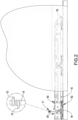
Fig. 2 is an enlarged perspective side view of the train forewarning braking system inFig. 1 ; -
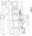
Fig. 3 is an enlarged perspective view of the train forewarning braking system inFig. 1 , disposed in a train; -
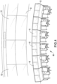
Fig. 4 is an enlarged perspective view of the train forewarning braking system inFig. 1 , disposed in a traffic control center; -
Fig. 5 is a circuit block diagram of the train forewarning braking system inFig. 1 ; -
Fig. 6 is an enlarged perspective view of a first embodiment of an auxiliary braking module of the train forewarning braking system in accordance with the present invention; -
Fig. 7 is an enlarged side view in partial section of the auxiliary braking module of the train forewarning braking system inFig. 6 ; -
Fig. 8 is an enlarged perspective view of a second embodiment of an auxiliary braking module of the train forewarning braking system in accordance with the present invention; -
Fig. 9 is an enlarged perspective view of a third embodiment of an auxiliary braking module of the train forewarning braking system in accordance with the present invention; -
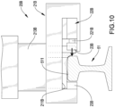
Fig. 10 is an enlarged and operational side view in partial section of the auxiliary braking module of the train forewarning braking system inFig. 9 , under an extended state; -
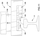
Fig. 11 is an enlarged and operational side view in partial section of the auxiliary braking module of the train forewarning braking system inFig. 9 , under a retracted state; -
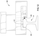
Fig. 12 is an enlarged side view in partial section of a fourth embodiment of an auxiliary braking module of the train forewarning braking system in accordance with the present invention; -
Fig. 13 is an enlarged side view of a fifth embodiment of an auxiliary braking module of the train forewarning braking system in accordance with the present invention; -
Fig. 14 is an operational perspective side view of the train forewarning braking system inFig. 1 ; -
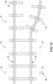
Fig. 15 is an operational top side view of a track detection module of the train forewarning braking system inFig. 1 ; and -
Fig. 16 is a further operational perspective view of the train forewarning braking system inFig. 1 . - With reference to
Figs. 1 to 5 , a train forewarning braking system in accordance with the present invention is disposed between atrain 40 and atrack 50 for thetrain 40 to travel on, is electrically connected to atraffic control center 60, and has animage monitoring module 10 and anauxiliary braking module 20. - The
image monitoring module 10 is disposed around thetrack 50 and is electrically connected to acontrol system 41 of thetrain 40. Thetrain 40 is electrically connected to thetraffic control center 60 via thecontrol system 41 to transmit images captured by theimage monitoring module 10 to thetraffic control center 60. Then images of historical file data such as previous images or images at a fixed time can be compared by manual judgment or artificial intelligence computer to check for warnings of dangers, so that the train operator can respond immediately with early warning. When it is detected that the train operator is suddenly disabled and cannot control thetrain 40, thetraffic control center 60 can intervene in time to control thetrain 40. When an emergency braking or major accident occurs, thetraffic control center 60 can be notified synchronously to dispatch thesubsequent train 40 to avoid a collision, and thetraffic control center 60 will notify rescue units such as the military, police, and hospitals to provide relevant assistance, thereby shortening the time required to rescue the injured. - The
image monitoring module 10 has multipleimage capture units 11,multiple display units 12, and anauxiliary unit 13. Theimage capture units 11 are disposed at spaced intervals near thetrack 50 and are electrically connected to thecontrol system 41 of thetrain 40, so that theimage capture units 11 may be disposed on two sides of thetrack 50 to capture images of the environment around thetrack 50. Preferably, with reference toFig. 2 , each one of theimage capture units 11 has afixed rod 14 and twocameras 15. Thefixed rod 14 is fixed on one of the two sides of thetrack 50. The twocameras 15 are disposed on the fixedrod 14 and respectively face two different directions, so as to capture the images of thetrain 40 approaching and moving away. With reference toFigs. 3 ,4 , and5 , thedisplay units 12 are disposed on thetrain 40 and thetraffic control center 60 and are electrically connected to thecontrol system 41, and images captured by each one of theimage capture units 11 are displayed on thedisplay units 12. In addition, theimage capture units 11 are disposed in sequence to capture images and thedisplay units 12 display the images sequentially. - With reference to
Fig. 13 , theauxiliary unit 13 may be an unmanned aerial vehicle (UAV) connected to thecontrol system 41 of thetrain 40 to capture the images around thetrain 40, transmit the images to thetrain 40, and display the images on one of thedisplay units 12 that is disposed on thetrain 40. Thereby, the images obtained by theimage monitoring module 10 and thetraffic control center 60 can be used to determine whether there is a fault or obstacle on thetrack 50 in front of thetrain 40, and immediately remind or provide a train operator (or an artificial intelligence computer) with an early warning or early braking operation. - Furthermore, with reference to
Figs. 2 and5 , theimage monitoring module 10 is equipped with a series of camera apparatus that are disposed on thetrain 40, in a cab of thetrain 40, around thetrack 50, around a level crossing, around a bridge, a tunnel or necessary locations. It can transmit real-time images of an upcoming traveling route of thetrain 40 from hundreds of meters to several kilometers away to thetrain 40 for reference to the train operator, thereby extending the driving visual range and responding in advance to improve the safety of driving thetrain 40. Furthermore, thetraffic control center 60 assists in paying attention to the conditions on the upcoming traveling route of thetrain 40. - According to the above, the
image monitoring module 10 has at least onephotography unit 16 disposed in front, behind, below or in a carriage of thetrain 40 to capture images of the front, rear, bottom and the carriage of thetrain 40 via the at least onephotography unit 16 and transmit the images to thecontrol system 41 and thetraffic control center 60 to determine whether there are obstacles in front and behind the traveling route of thetrain 40, whether thetrack 50 is broken, faulty or deformed, and provide real-time reminders or information to the train operator for performing an early warning or early braking operation. Furthermore, thephotography unit 16 disposed in the carriage of thetrain 40 can perform immediate and effective rescue and isolation for violent incidents in the carriage. When thetrain 40 encounters an emergency, anext train 40 on the same traveling route as thetrain 40 can be synchronously warned by thetraffic control center 60 to respond in advance to avoid a collision. - In addition, if the
traffic control center 60 determines that an unavoidable accident may occur with thetrain 40, thetraffic control center 60 can intervene with thetrain 40 via thecontrol system 41 to control and initiate emergency braking. With reference toFig. 3 , the train forewarning braking system has at least onedriving recorder 17 disposed in thetrain 40 to record travelling images and various data of thetrain 40, to check and observe the physical condition of the train operator, and to check whether the equipment is being operated correctly, etc., and this can provide an early warning braking judgment to an artificial intelligence or thetraffic control center 60. Additionally, accidents can be investigated to prevent similar accidents that may hinder the driving safety of thetrain 40 from happening again by using the at least onedriving recorder 17. - With reference to
Figs. 6 and7 , a first embodiment of theauxiliary braking module 20 of the present invention is disposed on thetrain 40, is electrically connected to thecontrol system 41, is disposed below thetrain 40 or on abogie 42 of thetrain 40 and facesrails 51 of thetrack 50. Theauxiliary braking module 20 has abody 21, adriving unit 22, and twoclamping units 23. Thebody 21 is securely mounted on a bottom of thebogie 42 and extends toward one of therails 51 of thetrack 50, is connected to thebogie 42 with an up-and-down sliding relationship, and has achamber 211 and an opening 212. Thechamber 211 is formed in thebody 21. The opening 212 is formed through a bottom of thebody 21, communicates with thechamber 211, and spans two sides of thecorresponding rail 51. Thecorresponding rail 51 has arail head 511 disposed in thechamber 211 of thebody 21 via the opening 212. - The driving
unit 22 is disposed in thechamber 211 of thebody 21, is disposed toward therail head 511 of the correspondingrail 51, and has a drivingrod 221 telescopically moved toward or away from therail head 511 of the correspondingrail 51. The twoclamping units 23 are disposed in thechamber 211 of thebody 21 and are respectively located at two sides of therail head 511 of the correspondingrail 51. One of the two clampingunits 23 is disposed on a side wall of thechamber 211 away from the drivingunit 22 and faces one of the two sides of therail head 511 of the correspondingrail 51, and the other one of the two clampingunits 23 is disposed on the drivingrod 221 of the drivingunit 22 and faces the other one of the two sides of therail head 511 of the correspondingrail 51. Preferably, with reference toFig. 5 , the train forewarning braking system of the present invention has two saidauxiliary braking modules 20 on eachbogie 42 of thetrain 40 to respectively dispose on the tworails 51 of thetrack 50. - Preferably, a required power of the driving
unit 22 can be provided by air brakes, hydraulic motors or magnetic means, and theauxiliary braking module 20 can be connected with brake shoes, disc brakes, and magnetic brakes of thetrain 40 or used alone as an emergency brake for thetrain 40. Theauxiliary braking module 20 can be disposed on the front, rear or each carriage of thetrain 40, and can act synchronously or sequentially depending on the situation. Furthermore, theauxiliary braking module 20 has an anti-lock brake system (ABS) and can be started intermittently to avoid excessive braking force causing slippage or damage to therail 51. In order to prevent therail 51 from being moved due to auxiliary braking by theauxiliary braking module 20, the foundation structure of therail 50 can be strengthened when therail 50 is constructed. - With reference to
Fig. 7 , when the first preferred embodiment of theauxiliary braking module 20 is in use, as thetrain 40 is braked by an air brake system, the drivingunit 22 can be synchronized to actuate via thecontrol system 41 to move the drivingrod 221 toward therail head 511 of the correspondingrail 51, and the two sides of therail head 511 of the correspondingrail 51 are respectively clamped by the two clampingunits 23. The clamping friction of the two clampingunits 23 provides an auxiliary braking effect for thetrain 40, which not only shortens the distance and reaction time required for braking thetrain 40, but also effectively improves the accuracy and safety of braking thetrain 40. - With reference to
Fig. 8 , a second embodiment of anauxiliary braking module 20A of a train forewarning braking system in accordance with the present invention is substantially the same as the first embodiment except for the following features. In the second embodiment of the present invention, the bottom of thebody 21A has a boat-shaped structure which can automatically raise and slide the correspondingrail 51 when it contacts a broken end of a turnout of the correspondingrail 51, thereby preventing thebody 21A from being stuck with the broken end of the turnout. Furthermore, theopening 212A of thebody 21A has a cross section same as a cross section of thechamber 211A, and this enables therail head 511 of the correspondingrail 51 to be arranged in thechamber 211A of thebody 21A. When the second embodiment of theauxiliary brake module 20A of the present invention is used, the operating principle and method of the second embodiment of theauxiliary brake module 20A are the same as those of the first embodiment of theauxiliary brake module 20, and will not be described here. - With reference to
Figs. 9 and10 , a third embodiment of anauxiliary braking module 20B of a train forewarning braking system in accordance with the present invention is substantially the same as the first embodiment except for the following features. In the third embodiment of the present invention, thebody 21B has a liftingrod 213B selectively moved toward or away from therail head 511 of the correspondingrail 51 to enable thedriving unit 22B and the two clampingunits 23B disposed in thechamber 211 of thebody 21B to approach or move away from therail head 511 of the correspondingrail 51 by a movement of the liftingrod 213B of thebody 21B. When the third embodiment of theauxiliary braking module 20B of the present invention is in use, as thetrain 40 is braked by the air brake system, the liftingrod 213B can be synchronized to move downwardly by thecontrol system 41 to move the two clampingunits 23B respectively facing the two sides of therail head 511 of the correspondingrail 51, and thedriving unit 22B also can be synchronized to actuate by thecontrol system 41 to move the two clampingunits 23B respectively toward and press against the two sides of therail head 511 of the correspondingrail 51 to provide an auxiliary braking effect for thetrain 40. - Furthermore, when the third embodiment of the
auxiliary braking module 20B of the present invention is used, the liftingrod 213B may be maintained under an extended state, so that the two clampingunits 23B are respectively maintained on two sides of the correspondingrail 51. In addition, with reference toFig. 11 , the liftingrod 213B may be maintained under a retracted state. When thetrain 40 is to brake, the liftingrod 213B is moved downwardly by thecontrol system 41 to move the two clampingunits 23B to respectively move on the two sides of the correspondingrail 51. With reference toFigs. 6 and9 , the at least onephotography unit 16 can be disposed on thebogie 42 of thetrain 40 to capture images of the tworails 51 of thetrack 50. - With reference to
Fig. 12 , a fourth embodiment of anauxiliary braking module 20C of a train forewarning braking system in accordance with the present invention is substantially the same as the third embodiment except for the following features. In the fourth embodiment of the present invention, each one of the two clampingunits 23C has a cross section being L-shaped, so that each clampingunit 23C can contact one of the two sides and a top surface of therail head 511 of the correspondingrail 51, thereby increasing the friction area to improve the braking force of thetrain 40 and to shorten the distance required for braking. Furthermore, theclamping unit 23C with the L-shaped cross section can also be applied to the above-mentioned first to third embodiments of the present invention, and is not limited here. Additionally, when the fourth embodiment of theauxiliary braking module 20C is used, the operating principle and method of the fourth embodiment of theauxiliary brake module 20C are the same as those of the third embodiment of theauxiliary brake module 20B, and will not be described here. - With reference to
Fig. 13 , a fifth embodiment of an auxiliary braking module of a train forewarning braking system in accordance with the present invention is substantially the same as the second and third embodiments except for the following features. In the fifth embodiment of the present invention, the train forewarning braking system has multiple said auxiliary braking modules disposed on each one of the tworails 51 of thetrack 50 at spaced intervals, and each of the multiple said auxiliary braking modules can be one of theauxiliary braking modules auxiliary braking modules rails 51 of thetrack 50 can be same or different, and are not limited here. In addition, the above-mentionedauxiliary braking modules train 40 or thebogie 42 according to the needs of the user and the type or structure of thetrain 40. - With reference to
Figs. 2 ,5 , and14 , according to the above-mentioned technical features, when the train forewarning braking system of the present invention is used, theimage monitoring module 10 at a relative position of thetrack 50 where thetrain 40 has not passed transmits images captured by thecameras 15 of theimage capture units 11 located at the relative position and in front of the relative position to thedisplay units 12 on thetrain 40. Then the train operator can judge whether there are safety concerns and need to consider braking through the image results of each relative position, and can also cooperate with theauxiliary unit 13 to capture relevant information at random points for the train operator to view and grasp the environmental conditions in the traveling route of thetrain 40. When theimage capture unit 11 located in the traveling route of thetrain 40 captures anobstacle 70 that may affect the safety of thetrain 40, the train operator can brake with enough time and distance to effectively avoid emergencies or accidents in a short distance to effectively achieve an effect of instant braking. - With reference to
Figs. 7 ,8 ,10 , and13 , during a braking process of the train forewarning braking system of the present invention, theauxiliary braking modules bogie 42 of thetrain 40 can be driven by thecontrol system 41 to activate the drivingunits units rail head 511 of a correspondingrail 51 to provide an auxiliary braking effect to thetrain 40. Then train forewarning braking system of the present invention can quickly achieve a safe and effective braking effect in a shorter time and distance for thetrain 40, can instantly and quickly carry out safety control of train driving, and effectively provide an early warning effect, improve driving safety, and provide an auxiliary braking effect. - Furthermore, in order to prevent the
auxiliary braking modules track 50 and being unable to brake effectively, providing images of thetrack 50 via thephotography units 16 of theimage monitoring module 10 or disposing position sensing-transmitting devices on eachrail 51 to determine that theauxiliary braking module auxiliary braking module train 40 after the turnout to avoid mis-clamping or causing thetrain 40 off thetrack 50 due to collision between theauxiliary braking modules - With reference to
Figs. 5 and15 , the train forewarning braking system of the present invention has atrack detection module 30 disposed on two sides of the tworails 51 of thetrack 50 to detect whether the tworails 51 are broken or bent. Thetrack detection module 30 is electrically connected to thecontrol system 41 of thetrain 40 and thetraffic control center 60, detects and sends information of the tworails 51 to thecontrol system 41 and thetraffic control center 60, allowing the train operator and personnel of thetraffic control center 60 to monitor and confirm the status of thetrack 50. Thetrack detection module 30 hasmultiple sensors 31 disposed on one of two sides of each one of the tworails 51 at a spaced interval to detect whether the shape of the correspondingrail 51 is abnormal (broken or bent, etc.). - Furthermore, with reference to
Fig. 16 , at least one of saidimage capture units 11 is disposed on two sides of a level crossing, or at least one of saidimage capture units 11 is disposed on two sides of two directions of a road, and the twocameras 15 of each one of theimage capture units 11 respectively face two different directions of thetrack 50. Theimage monitoring module 10 has awarning device 18 such as lights or sounds disposed on the fixedrod 14 of each one of theimage capture units 11. If there are obstacles such as animals, pedestrians or vehicles on thetrack 50, thewarning devices 18 on the fixedrods 14 can be used to provide an effect of driving away. In addition, each one of theimage capture units 11 of theimage monitoring module 10 captures images of slope slip conditions and bridge conditions around thetrack 50 and transmits images back to thetrain 40 and thetraffic control center 60 to provide monitoring effects on the slope slip conditions and bridge conditions. - Additionally, images and signals of the train forewarning braking system of the present invention can be transmitted wirelessly such as via 5G transmission, and can be transmitted by wired contact on the
train 40 in a traveling route. For example, a power supply system uses a carrier wave type or wired transmission on thetrack 50 to transmit images and signals to thetraffic control center 60 and thecontrol system 41 of thetrain 40. When thetrain 40 moves into a tunnel, if there is an obstacle in wireless signal transmission, it can be switched to wired contact transmission to ensure signal reliability. Moreover, when transmitting signals wirelessly, a communication base station can be used in conjunction with lines of thetrack 50, a radio, a communication base station, or wireless satellite to transmit signals. - Even though numerous characteristics and advantages of the present invention have been set forth in the foregoing description, together with details of the structure and features of the invention, the disclosure is illustrative only. Changes may be made in the details, especially in matters of shape, size, and arrangement of parts within the principles of the invention to the full extent indicated by the broad general meaning of the terms in which the appended claims are expressed.
Claims (17)
- A train forewarning braking system disposed between a train (40) and a track (50) for the train (40) to travel on, electrically connected to a traffic control center (60), and characterized in that the train forewarning braking system comprises:
an image monitoring module (10) disposed around the track (50), electrically connected to a control system (41) of the train (40) and the traffic control center (60), and havingmultiple image capture units (11) disposed at spaced intervals near the track (50) and electrically connected to the control system (41) of the train (40) to capture images of the environment around the track (50); andmultiple display units (12) disposed on the train (40) and the traffic control center (60), and electrically connected to the control system (41) to display the images captured by each one of the image capture units (11). - The train forewarning braking system as claimed in claim 1, wherein the train forewarning braking system has an auxiliary braking module (20, 20A, 20B, 20C) disposed on the train (40), electrically connected to the control system (41), and disposed below the train (40) and faced the track (50).
- The train forewarning braking system as claimed in claim 1, whereinthe train forewarning braking system has an auxiliary braking module (20, 20A, 20B, 20C) disposed on the train (40), electrically connected to the control system (41), and disposed on a bogie (42) of the train (40) and faced the track (50); andthe auxiliary braking module (20, 20A, 20B, 20C) hasa body (21, 21A, 21B) securely mounted on a bottom of the bogie (42), extended toward one of two rails (51) of the track (50), and havinga chamber (211, 211A) formed in the body (21, 21A, 21B); andan opening (212, 212A) formed through a bottom of the body (21, 21A, 21B), communicating with the chamber (211, 211A), and span two sides of the corresponding rail (51) to enable a rail head (511) of the corresponding rail (51) to be mounted in the chamber (211, 211A);a driving unit (22, 22B) disposed in the chamber (211, 211A) of the body (21, 21A, 21B) and disposed toward the rail head (511) of the corresponding rail (51); andtwo clamping units (23, 23B, 23C) disposed in the chamber (211, 211A) of the body (21, 21A, 21B), respectively located at two sides of the rail head (511) of the corresponding rail (51), one of the two clamping units (23, 23B, 23C) disposed on a side wall of the chamber (211, 211A) away from the driving unit (22, 22B) and faced one of the two sides of the rail head (511) of the corresponding rail (51), and the other one of the two clamping units (23, 23B, 23C) disposed on the driving unit (22, 22B) and faced the other one of the two sides of the rail head (511) of the corresponding rail (51).
- The train forewarning braking system as claimed in any one of claims 1 to 3, wherein each one of the multiple image capture units (11) hasa fixed rod (14) securely mounted near the track (50); andtwo cameras (15) disposed on the fixed rod (14), electrically connected to the control system (41) of the train (40), and respectively faced two different directions to capture images of the train (40) approaching and moving away.
- The train forewarning braking system as claimed in any one of claims 1 to 3, wherein the image monitoring module (10) has an auxiliary unit (13) being an unmanned aerial vehicle, connected to the control system (41) of the train (40) to capture images around the train (40), transmitting the images to the train (40), and displaying the images on one of the display units (12).
- The train forewarning braking system as claimed in claim 3, whereinthe driving unit (22, 22B) of the auxiliary braking module (20, 20B) has a driving rod (221, 221B) telescopically moved toward or away from the rail head (511) of the corresponding rail (51); andone of the two clamping units (23, 23B) is disposed on the driving rod (221, 221B) of the driving unit (22, 22B) to face one of the two sides of the rail head (511) of the corresponding rail (51).
- The train forewarning braking system as claimed in claim 3, whereinthe bottom of the body (21A) has a boat-shaped structure; andthe opening (212A) of the body (21A) has a cross section same as a cross section of the chamber (211A) to arrange the rail head (511) of the corresponding rail (51) in the chamber (211A) of the body (21A).
- The train forewarning braking system as claimed in claim 3, wherein the body (21B) of the auxiliary braking module (20B) has a lifting rod (213B) selectively moved toward or away from the rail head (511) of the corresponding rail (51) to enable the driving unit (22B) and the two clamping units (23B) disposed in the chamber of the body (21B) to approach or move away from the rail head (511) of the corresponding rail (51).
- The train forewarning braking system as claimed in claim 3, wherein each one of the two clamping units (23C) has a cross section being L-shaped to enable the clamping unit (23C) to contact one of the two sides and a top surface of the rail head (511) of the corresponding rail (51).
- The train forewarning braking system as claimed in claim 2 or 3, wherein the train forewarning braking system has multiple said auxiliary braking modules (20, 20A, 20B, 20C) disposed on the track (50) at spaced intervals.
- The train forewarning braking system as claimed in any one of claims 1 to 3, wherein the image monitoring module (10) has at least one photography unit (16) disposed in front, behind, below or in a carriage of the train (40), capturing images of the front, rear, bottom or the carriage of the train (40), and transmitting the images to the control system (41) and the traffic control center (60).
- The train forewarning braking system as claimed in claim 11, wherein the said at least one photography unit (16) is disposed on a bogie (42) of the train (40) to capture images of two rails (51) of the track (50).
- The train forewarning braking system as claimed in claim 12, wherein the train forewarning braking system has at least one driving recorder (17) disposed in the train (40).
- The train forewarning braking system as claimed in any one of claims 1 to 3, wherein the train forewarning braking system has a track detection module (30) disposed on two sides of two rails (51) of the track (50) to detect whether the two rails (51) are broken or bent, electrically connected to the control system (41) of the train (40) and the traffic control center (60), and detecting and sending information of the two rails (51) of the track (50) to the control system (41) and the traffic control center (60).
- The train forewarning braking system as claimed in claim 14, wherein the track detection module (30) has multiple sensors (31) disposed on one of the two sides of each one of the two rails (51) at spaced intervals to detect whether the shape of the corresponding rail (51) is abnormal.
- The train forewarning braking system as claimed in any one of claims 1 to 3, wherein each one of the image capture units (11) of the image monitoring module (10) has a warning device (18).
- The train forewarning braking system as claimed in any one of claims 1 to 3, wherein each one of image capture units (11) of the image monitoring module (10) captures images of slope slip conditions and bridge conditions around the track (50) and transmits images back to the train (40) and the traffic control center (60).
Applications Claiming Priority (1)
| Application Number | Priority Date | Filing Date | Title |
|---|---|---|---|
| TW111150968A TWI847469B (en) | 2022-12-30 | 2022-12-30 | Train Early Warning Braking System |
Publications (2)
| Publication Number | Publication Date |
|---|---|
| EP4403435A2 true EP4403435A2 (en) | 2024-07-24 |
| EP4403435A3 EP4403435A3 (en) | 2024-10-02 |
Family
ID=89321994
Family Applications (1)
| Application Number | Title | Priority Date | Filing Date |
|---|---|---|---|
| EP23219639.4A Pending EP4403435A3 (en) | 2022-12-30 | 2023-12-22 | Train forewarning braking system |
Country Status (4)
| Country | Link |
|---|---|
| US (1) | US12522267B2 (en) |
| EP (1) | EP4403435A3 (en) |
| JP (1) | JP2024096041A (en) |
| TW (1) | TWI847469B (en) |
Family Cites Families (15)
| Publication number | Priority date | Publication date | Assignee | Title |
|---|---|---|---|---|
| ATE322416T1 (en) * | 2000-12-07 | 2006-04-15 | Siemens Schweiz Ag | METHOD FOR IMAGINING THE TRACK CONDITION AND/OR THE MECHANICAL OPERATING BEHAVIOR OF RAIL VEHICLES |
| WO2002074602A1 (en) | 2001-03-20 | 2002-09-26 | Brent Felix Jury | Braking apparatus and method |
| US9873442B2 (en) * | 2002-06-04 | 2018-01-23 | General Electric Company | Aerial camera system and method for identifying route-related hazards |
| US11208129B2 (en) * | 2002-06-04 | 2021-12-28 | Transportation Ip Holdings, Llc | Vehicle control system and method |
| DE102004015244B4 (en) * | 2004-03-29 | 2007-04-05 | Siemens Ag | Method and device for monitoring the track position quality |
| CN101020466A (en) * | 2006-02-13 | 2007-08-22 | 申朗 | Over-the-horizon and curve observing system for railway train |
| TWI526354B (en) * | 2013-12-23 | 2016-03-21 | 國立高雄應用科技大學 | Railway monitoring system |
| WO2016015759A1 (en) * | 2014-07-30 | 2016-02-04 | Gravity Transport System S.A. | Rail vehicle braking system |
| US9434397B2 (en) * | 2014-08-05 | 2016-09-06 | Panasec Corporation | Positive train control system and apparatus therefor |
| PL239778B1 (en) * | 2017-10-02 | 2022-01-10 | Skytech Res Spolka Z Ograniczona Odpowiedzialnoscia | A system for warning about threats, especially in rail transport |
| JP7153000B2 (en) * | 2019-09-17 | 2022-10-13 | 株式会社日立製作所 | train control system |
| CN111717243B (en) * | 2020-06-22 | 2022-04-01 | 成都希格玛光电科技有限公司 | Rail transit monitoring system and method |
| US11823578B2 (en) * | 2021-02-16 | 2023-11-21 | Easy Aerial Inc. | Unmanned aerial vehicle (UAV) systems and methods for maintaining railway situational awareness |
| ES2886582A1 (en) * | 2021-06-03 | 2021-12-20 | Ostirion S L U | PROCEDURE AND SPEED AND POSITION DETECTION EQUIPMENT OF A RAILROAD VEHICLE (Machine-translation by Google Translate, not legally binding) |
| DE102021206116A1 (en) * | 2021-06-15 | 2022-12-15 | Thales Management & Services Deutschland Gmbh | Process for safe train remote control, whereby images are processed via two processing lines |
-
2022
- 2022-12-30 TW TW111150968A patent/TWI847469B/en active
-
2023
- 2023-12-22 EP EP23219639.4A patent/EP4403435A3/en active Pending
- 2023-12-25 JP JP2023218458A patent/JP2024096041A/en active Pending
- 2023-12-27 US US18/396,928 patent/US12522267B2/en active Active
Also Published As
| Publication number | Publication date |
|---|---|
| TWI847469B (en) | 2024-07-01 |
| US12522267B2 (en) | 2026-01-13 |
| TW202426312A (en) | 2024-07-01 |
| US20240217568A1 (en) | 2024-07-04 |
| JP2024096041A (en) | 2024-07-11 |
| EP4403435A3 (en) | 2024-10-02 |
Similar Documents
| Publication | Publication Date | Title |
|---|---|---|
| US11039055B2 (en) | Video system and method for data communication | |
| JP3342017B2 (en) | Fault detection system | |
| US9873442B2 (en) | Aerial camera system and method for identifying route-related hazards | |
| JP7153000B2 (en) | train control system | |
| CN113415318B (en) | Train coupling marshalling auxiliary protection system and protection method | |
| US8400270B2 (en) | Systems and methods for determining an operating state using RFID | |
| CN106043126A (en) | Heavy truck steering early warning auxiliary device and early warning method | |
| CN104908782A (en) | Safety pre-warning method and system device for locomotive shunting operation | |
| WO2015123035A1 (en) | Video system and method for data communication | |
| CN110789574A (en) | Train barrier detection and comprehensive early warning protection system | |
| KR20050062889A (en) | Train emergency control system and method using unexpected accident image detector | |
| CN202186403U (en) | Anti-collision device for locomotive | |
| US12522267B2 (en) | Train forewarning braking system | |
| JP6772356B2 (en) | Train connection support system | |
| CN111409670B (en) | Auxiliary monitoring system and method | |
| RU94202U1 (en) | ELECTROTECHNICAL COMPLEX FOR PREVENTING ACCIDENT SITUATIONS ON RAILWAYS | |
| CN219215037U (en) | Train warning brake system | |
| CN212796683U (en) | Intelligent recognition's safe driving early warning system | |
| CN211718518U (en) | Forward-looking obstacle detection system | |
| CN118343184A (en) | Train early warning braking system | |
| TWM643247U (en) | Train early warning and braking system | |
| RU134889U1 (en) | RAILWAY PROTECTION SYSTEM | |
| CN219257353U (en) | Automatic collision avoidance system for railway end line propulsion shunting | |
| KR100497311B1 (en) | Method for automatically detecting and alarming unexpected accident while boarding or alighting from subway and train at platform | |
| KR200345401Y1 (en) | Train emergency control system using unexpected accident image detector |
Legal Events
| Date | Code | Title | Description |
|---|---|---|---|
| PUAI | Public reference made under article 153(3) epc to a published international application that has entered the european phase |
Free format text: ORIGINAL CODE: 0009012 |
|
| STAA | Information on the status of an ep patent application or granted ep patent |
Free format text: STATUS: THE APPLICATION HAS BEEN PUBLISHED |
|
| AK | Designated contracting states |
Kind code of ref document: A2 Designated state(s): AL AT BE BG CH CY CZ DE DK EE ES FI FR GB GR HR HU IE IS IT LI LT LU LV MC ME MK MT NL NO PL PT RO RS SE SI SK SM TR |
|
| PUAL | Search report despatched |
Free format text: ORIGINAL CODE: 0009013 |
|
| AK | Designated contracting states |
Kind code of ref document: A3 Designated state(s): AL AT BE BG CH CY CZ DE DK EE ES FI FR GB GR HR HU IE IS IT LI LT LU LV MC ME MK MT NL NO PL PT RO RS SE SI SK SM TR |
|
| RIC1 | Information provided on ipc code assigned before grant |
Ipc: B61H 7/12 20060101ALI20240827BHEP Ipc: B61L 27/53 20220101ALI20240827BHEP Ipc: B61L 23/04 20060101ALI20240827BHEP Ipc: B61L 15/00 20060101AFI20240827BHEP |
|
| STAA | Information on the status of an ep patent application or granted ep patent |
Free format text: STATUS: REQUEST FOR EXAMINATION WAS MADE |
|
| 17P | Request for examination filed |
Effective date: 20250325 |