EP4403403A1 - Methode zur steuerung eines elektrisch betriebenen fahrzeugs - Google Patents
Methode zur steuerung eines elektrisch betriebenen fahrzeugs Download PDFInfo
- Publication number
- EP4403403A1 EP4403403A1 EP24151790.3A EP24151790A EP4403403A1 EP 4403403 A1 EP4403403 A1 EP 4403403A1 EP 24151790 A EP24151790 A EP 24151790A EP 4403403 A1 EP4403403 A1 EP 4403403A1
- Authority
- EP
- European Patent Office
- Prior art keywords
- power
- electric
- electric motor
- power loss
- control method
- Prior art date
- Legal status (The legal status is an assumption and is not a legal conclusion. Google has not performed a legal analysis and makes no representation as to the accuracy of the status listed.)
- Pending
Links
Images

Classifications
-
- B—PERFORMING OPERATIONS; TRANSPORTING
- B60—VEHICLES IN GENERAL
- B60L—PROPULSION OF ELECTRICALLY-PROPELLED VEHICLES; SUPPLYING ELECTRIC POWER FOR AUXILIARY EQUIPMENT OF ELECTRICALLY-PROPELLED VEHICLES; ELECTRODYNAMIC BRAKE SYSTEMS FOR VEHICLES IN GENERAL; MAGNETIC SUSPENSION OR LEVITATION FOR VEHICLES; MONITORING OPERATING VARIABLES OF ELECTRICALLY-PROPELLED VEHICLES; ELECTRIC SAFETY DEVICES FOR ELECTRICALLY-PROPELLED VEHICLES
- B60L15/00—Methods, circuits, or devices for controlling the traction-motor speed of electrically-propelled vehicles
- B60L15/20—Methods, circuits, or devices for controlling the traction-motor speed of electrically-propelled vehicles for control of the vehicle or its driving motor to achieve a desired performance, e.g. speed, torque, programmed variation of speed
- B60L15/2045—Methods, circuits, or devices for controlling the traction-motor speed of electrically-propelled vehicles for control of the vehicle or its driving motor to achieve a desired performance, e.g. speed, torque, programmed variation of speed for optimising the use of energy
-
- B—PERFORMING OPERATIONS; TRANSPORTING
- B60—VEHICLES IN GENERAL
- B60L—PROPULSION OF ELECTRICALLY-PROPELLED VEHICLES; SUPPLYING ELECTRIC POWER FOR AUXILIARY EQUIPMENT OF ELECTRICALLY-PROPELLED VEHICLES; ELECTRODYNAMIC BRAKE SYSTEMS FOR VEHICLES IN GENERAL; MAGNETIC SUSPENSION OR LEVITATION FOR VEHICLES; MONITORING OPERATING VARIABLES OF ELECTRICALLY-PROPELLED VEHICLES; ELECTRIC SAFETY DEVICES FOR ELECTRICALLY-PROPELLED VEHICLES
- B60L50/00—Electric propulsion with power supplied within the vehicle
-
- B—PERFORMING OPERATIONS; TRANSPORTING
- B60—VEHICLES IN GENERAL
- B60L—PROPULSION OF ELECTRICALLY-PROPELLED VEHICLES; SUPPLYING ELECTRIC POWER FOR AUXILIARY EQUIPMENT OF ELECTRICALLY-PROPELLED VEHICLES; ELECTRODYNAMIC BRAKE SYSTEMS FOR VEHICLES IN GENERAL; MAGNETIC SUSPENSION OR LEVITATION FOR VEHICLES; MONITORING OPERATING VARIABLES OF ELECTRICALLY-PROPELLED VEHICLES; ELECTRIC SAFETY DEVICES FOR ELECTRICALLY-PROPELLED VEHICLES
- B60L2240/00—Control parameters of input or output; Target parameters
- B60L2240/40—Drive Train control parameters
- B60L2240/42—Drive Train control parameters related to electric machines
- B60L2240/423—Torque
-
- B—PERFORMING OPERATIONS; TRANSPORTING
- B60—VEHICLES IN GENERAL
- B60L—PROPULSION OF ELECTRICALLY-PROPELLED VEHICLES; SUPPLYING ELECTRIC POWER FOR AUXILIARY EQUIPMENT OF ELECTRICALLY-PROPELLED VEHICLES; ELECTRODYNAMIC BRAKE SYSTEMS FOR VEHICLES IN GENERAL; MAGNETIC SUSPENSION OR LEVITATION FOR VEHICLES; MONITORING OPERATING VARIABLES OF ELECTRICALLY-PROPELLED VEHICLES; ELECTRIC SAFETY DEVICES FOR ELECTRICALLY-PROPELLED VEHICLES
- B60L2240/00—Control parameters of input or output; Target parameters
- B60L2240/40—Drive Train control parameters
- B60L2240/42—Drive Train control parameters related to electric machines
- B60L2240/427—Voltage
-
- Y—GENERAL TAGGING OF NEW TECHNOLOGICAL DEVELOPMENTS; GENERAL TAGGING OF CROSS-SECTIONAL TECHNOLOGIES SPANNING OVER SEVERAL SECTIONS OF THE IPC; TECHNICAL SUBJECTS COVERED BY FORMER USPC CROSS-REFERENCE ART COLLECTIONS [XRACs] AND DIGESTS
- Y02—TECHNOLOGIES OR APPLICATIONS FOR MITIGATION OR ADAPTATION AGAINST CLIMATE CHANGE
- Y02T—CLIMATE CHANGE MITIGATION TECHNOLOGIES RELATED TO TRANSPORTATION
- Y02T10/00—Road transport of goods or passengers
- Y02T10/60—Other road transportation technologies with climate change mitigation effect
- Y02T10/72—Electric energy management in electromobility
Definitions
- An electric drive vehicle can be provided with only one or more electric motors (and in this case the drive is exclusively electric) or can be provided with one or more electric motors in combination with a thermal engine (and in this case the drive can be exclusively electric, exclusively thermal or also hybrid).
- the electric motor (or each electric motor) is mechanically connected to the drive wheels and is electrically connected to an electric energy storage system through the interposition of an electronic power converter (namely, an inverter) which performs the conversion of the electric energy from direct (on the side connected to the storage system) to alternating (on the side connected to the electric motor) and vice versa.
- an electronic power converter namely, an inverter
- the electronic power converter preferably comprises (at least) two modules which are connected to one another in parallel.
- Patent application US2014121867A1 describes a method to control a hybrid powertrain with multiple electric motors to reduce the total electrical power losses.
- the control method provides for determining a first electrical power loss value in the operation of a first and of a second electric machine with the power inverters of both electric machines in an active mode, a second electrical power loss value in the operation with the power inverter of the first electric machine in an active mode and the power inverter of the second electric machine in a standby mode, and a third electrical power loss value in the operation with the power inverter of the second electric machine in an active mode and the power inverter of the first electric machine in a standby mode; a controller sets the power inverters in the operation that has the lowest electrical power loss.
- Patent application DE102020216248A1 describes a method to control an at least partially electric drive vehicle provided with two electric machines mechanically connected to a same output shaft.
- the object of the present invention is to provide a method to control an electric drive vehicle which allows maximizing in every operating condition the energy efficiency of the electric/electronic components (namely, allows reducing in every operating condition the power losses which take place in the electric/electronic components.
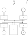
- reference numeral 1 indicates, as a whole, a vehicle with electric propulsion provided with four drive wheels 2 (two front drive wheels 2 and two rear drive wheels 2) .
- the vehicle 1 comprises an electric powertrain system 3 arranged in a front position (namely, is connected to the two front drive wheels 2) and an electric powertrain system 3 which is arranged in a rear position (namely, is connected to the two rear drive wheels 2), is structurally identical to the electric powertrain system 3 arranged in a front position, and is mechanically independent of and separate from the electric powertrain system 3 arranged in a front position.
- the vehicle 1 comprises one single electric powertrain system 3 (arranged in a front position or arranged in a rear position) and thus has only two drive wheels 2; in this embodiment, the vehicle 1 could also comprise a thermal powertrain system (not illustrated) connected to the drive wheels 2 which do not receive the motion from the electric powertrain system 3 and the thermal powertrain system could be provided with a further electric motor (not illustrated) connected to the drive shaft of an internal combustion heat engine.
- Each electric powertrain system 3 comprises a pair of reversible electric motors 4 (i.e. that can operate both as electric motor absorbing electric energy and generating a mechanical torque, and as electric generator absorbing mechanical energy and generating electric energy) provided with respective shafts and a pair of transmissions 5 which connect the electric motors 4 (namely, the shafts of the electric motors 4) to the corresponding drive wheels 2 without the interposition of any friction.
- a pair of reversible electric motors 4 i.e. that can operate both as electric motor absorbing electric energy and generating a mechanical torque, and as electric generator absorbing mechanical energy and generating electric energy
- transmissions 5 which connect the electric motors 4 (namely, the shafts of the electric motors 4) to the corresponding drive wheels 2 without the interposition of any friction.
- a high voltage electrical system 8 of the vehicle 1 comprises four electronic power converters 6 which are structurally identical to one another and each power a respective electric motor 4.
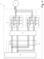
- each (indifferently front or rear) electronic power converter 6 comprises two twin power modules 9 (namely, identical to one another), each of which is adapted to power in alternating current the three phases of a corresponding electric motor 4.
- Each power module 9 is provided with respective transistors 10 each having a gate 11; obviously, the wiring diagram of a power module 9 illustrated in Figure 3 is only one possible non-limiting example and thus the power modules 9 could have any other wiring diagram (without prejudice to the presence of transistors 10 each having a gate 11).
- Each electronic power converter 6 comprises a driving device 12 of the gate which is connected to the gates 11 of the transistors 10 of the power modules 9.
- Each electronic power converter 6 comprises a control unit 13 which supervises the operation of the entire electronic power converter 6 and is connected to the driving device 12 of the gate. Namely, there is an electrical (physical) connection between the control unit 13 and the driving device 12 of the gate and there is a further electrical (physical) connection between the driving device 12 of the gate and the power modules 9.
- all the control logic is implemented in the control unit 13 which constitutes the "brain" of the electronic power converter 6; each control unit 13 normally comprises an electronic circuit which is provided with a (at least one) microprocessor.
- an enabling device 14 is interposed which is provided with respective switches which allow, under the control of the control unit 13, connecting or insulating the driving device 12 of the gate to/from the control unit 13.
- the enabling device 14 is illustrated as a physical element separate from the control unit 13, but obviously the enabling device 14 could be a virtual element integrated in the control unit 13.
- control unit 13 is configured to determine an intensity of an electric current I to be supplied by each electronic power converter 6 to the respective electric motor 4 (the electric current I is positive when the electric motor 4 absorbs electric power for generating mechanical power and is negative when the electric motor 4 absorbs mechanical power for generating electric power).
- the mechanical torque to be generated/absorbed by each electric motor 4 is determined in advance and thus the desired intensity of the electric current I to be supplied by the respective electronic power converter 6 is calculated depending on the mechanical torque.
- control unit 13 is configured to compare the desired intensity of the electric current I with a threshold value (obviously only the module of the desired intensity of the electric current I is used for the comparison, thus eliminating the mark); the threshold value corresponds to the (maximum) rated current deliverable by each power module 9. If the desired intensity of the electric current I exceeds the threshold value, then the control unit 13 always uses both power modules 9 to supply the electric current I to the electric motor 4; in fact, one single power module 9 is not capable of delivering on its own an electric current I exceeding the threshold value and it is thus necessary to use both power modules 9 if the desired intensity of the electric current I exceeds the threshold value.
- the control unit 13 is configured to use both power modules 9 to supply the electric current I to the electric motor 4 if the second power loss (with two active power modules 9) is smaller than the first power loss (with one single active power module 9) and to use one single power module 9 to supply the electric current I to the electric motor 4 if the second power loss (with two active power modules 9) is greater than the first power loss (with one single active power module 9).
- the control unit 13 estimates the total power loss in the power modules 9 mainly depending on the desired intensity of the electric current I to be supplied by the electronic power converter 6 to the electric motor 4 and possibly also depending on a temperature of the power modules 9, on an electric DC supply voltage (which varies upon the varying of the charge state of the storage system 7), and/or on a control frequency of the power modules 9.
- the control unit 13 cyclically switches the active power module 9 when one single power module 9 is used to supply the electric current I to the electric motor 4; in this manner, the wear and especially the heating are divided on both power modules 9 reducing the average working temperature of the power modules 9 to the full advantage of the efficiency (which decreases upon the increase in the temperature due to the increase in the electrical resistivity of the materials, and thus to the power losses by Joule effect, upon the increase in the temperature). Since the heating of the power modules 9 is a relatively slow phenomenon, the cyclical switching of the active power module 9 can take place with a relatively slow frequency (for example a switching every 30-60-90 or more seconds).
- control unit 13 uses a map (table) to estimate the total power loss in the power modules 9.
- control unit 13 uses a mathematical model to estimate the total power loss in the power modules 9.
- the vehicle 1 comprises a control unit 15 which is configured to determine the mechanical torque to be generated/absorbed by each electric motor 4 and thus establishes the objective to be pursued by each electronic power converter 6 (namely, the control unit 15 is hierarchically greater than the control units 13 of the single electronic power converters 6 for which it establishes the objectives).
- control unit 15 is configured to determine a desired torque to be totally generated by the front and rear electric motors 4 (the desired torque is positive when the electric motors 4 absorb electric power for generating mechanical torque so as to accelerate the vehicle 1 and is negative when the electric motors 4 absorb mechanical power for generating electric power so as to brake the vehicle 1).
- control unit 15 is configured to compare the desired torque with a threshold value (obviously, only the module of the desired torque is used for the comparison thus eliminating the mark); the threshold value corresponds to the (maximum) desired rated torque deliverable by each axle (namely, by the front axle in which the two front electric motors 4 are installed and by the rear axle in which the two rear electric motors 4 are installed).
- the control unit 13 always uses both axles (namely, the two front electric motors 4 and the two rear electric motors 4) for generating the desired torque; in fact, an (a front or rear) axle is not capable of generating on its own a desired torque exceeding the threshold value and it is thus necessary to use both axles (namely, the two front electric motors 4 and the two rear electric motors 4) if the desired torque exceeds the threshold value.
- the control unit 15 is configured to estimate a first total power loss in the electric motors 4 using one single axle (namely, only the two front electric motors 4 or only the two rear electric motors 4) for generating the torque and, simultaneously, for estimating a second total power loss in the electric motors 4 using both axles (namely, the two front electric motors 4 and the two rear electric motors 4) for generating the torque.
- the control unit 15 is configured to use both axles (namely, the two front electric motors 4 and the two rear electric motors 4) for generating the torque if the second power loss (with the two active axles) is smaller than the first power loss (with one single active axle) and to use one single axle (namely, the two front electric motors 4 or the two rear electric motors 4) for generating the torque if the second power loss (with two active axles) is greater than the first power loss (with one single active axle).
- the control unit 13 cyclically switches the active axle when one single axle is used for generating the torque; in this manner, the wear and especially the heating are divided on both axles reducing the average working temperature of the electric motors 4 and of the electronic power converters 6 to the full advantage of the efficiency (which decreases upon the increase in the temperature due to the increase in the electrical resistivity of the materials, and thus to the power losses by Joule effect, upon the increase in the temperature). Since the heating of the electric motors 4 and of the electronic power converters 6 is a relatively slow phenomenon, the cyclical switching of the active axle can take place with a relatively slow frequency (for example a switching every 1-3-5 or more minutes).
- control unit 13 uses a map (table) to estimate the total power loss in the electric motors 4.
- control unit 13 uses a mathematical model for estimating the total power loss in the electric motors 4.
- the above-described control method allows maximizing in every operating condition the energy efficiency of the electric/electronic components (namely, allows reducing in every operating condition the power losses which take place in the electric/electronic components).
Landscapes
- Engineering & Computer Science (AREA)
- Power Engineering (AREA)
- Transportation (AREA)
- Mechanical Engineering (AREA)
- Electric Propulsion And Braking For Vehicles (AREA)
Applications Claiming Priority (1)
| Application Number | Priority Date | Filing Date | Title |
|---|---|---|---|
| IT202300000558 | 2023-01-17 |
Publications (1)
| Publication Number | Publication Date |
|---|---|
| EP4403403A1 true EP4403403A1 (de) | 2024-07-24 |
Family
ID=85792568
Family Applications (1)
| Application Number | Title | Priority Date | Filing Date |
|---|---|---|---|
| EP24151790.3A Pending EP4403403A1 (de) | 2023-01-17 | 2024-01-15 | Methode zur steuerung eines elektrisch betriebenen fahrzeugs |
Country Status (2)
| Country | Link |
|---|---|
| US (1) | US12576728B2 (de) |
| EP (1) | EP4403403A1 (de) |
Citations (3)
| Publication number | Priority date | Publication date | Assignee | Title |
|---|---|---|---|---|
| WO1993005977A1 (en) * | 1991-09-25 | 1993-04-01 | Frazer-Nash Technology Limited | Electric car |
| US20140121867A1 (en) | 2012-11-01 | 2014-05-01 | GM Global Technology Operations LLC | Method of controlling a hybrid powertrain with multiple electric motors to reduce electrical power losses and hybrid powertrain configured for same |
| DE102020216248A1 (de) | 2020-12-18 | 2022-06-23 | Zf Friedrichshafen Ag | Verfahren zum Antrieb eines zumindest teilweise elektrisch angetriebenen Fahrzeugs sowie Getriebeanordnung und Antriebsvorrichtung für ein solches Fahrzeug |
Family Cites Families (1)
| Publication number | Priority date | Publication date | Assignee | Title |
|---|---|---|---|---|
| EP3530516B1 (de) * | 2018-02-23 | 2022-07-06 | Ningbo Geely Automobile Research & Development Co. Ltd. | Elektrisches batteriesystem |
-
2024
- 2024-01-12 US US18/411,194 patent/US12576728B2/en active Active
- 2024-01-15 EP EP24151790.3A patent/EP4403403A1/de active Pending
Patent Citations (3)
| Publication number | Priority date | Publication date | Assignee | Title |
|---|---|---|---|---|
| WO1993005977A1 (en) * | 1991-09-25 | 1993-04-01 | Frazer-Nash Technology Limited | Electric car |
| US20140121867A1 (en) | 2012-11-01 | 2014-05-01 | GM Global Technology Operations LLC | Method of controlling a hybrid powertrain with multiple electric motors to reduce electrical power losses and hybrid powertrain configured for same |
| DE102020216248A1 (de) | 2020-12-18 | 2022-06-23 | Zf Friedrichshafen Ag | Verfahren zum Antrieb eines zumindest teilweise elektrisch angetriebenen Fahrzeugs sowie Getriebeanordnung und Antriebsvorrichtung für ein solches Fahrzeug |
Also Published As
| Publication number | Publication date |
|---|---|
| US20240239209A1 (en) | 2024-07-18 |
| US12576728B2 (en) | 2026-03-17 |
Similar Documents
| Publication | Publication Date | Title |
|---|---|---|
| KR101113191B1 (ko) | 전원장치 및 차량 | |
| JP6774519B2 (ja) | マルチチャネルdcバスを有する車両推進システムおよび同システムを製造する方法 | |
| KR102797776B1 (ko) | 배터리 팩 가열 방법, 배터리 가열 시스템 및 전기 장치 | |
| JP5844787B2 (ja) | 補助駆動装置及びその製造方法 | |
| US6078163A (en) | Battery temperature increasing device and method | |
| US8800521B2 (en) | Electric vehicle fluid preheater | |
| US20130330578A1 (en) | Method and device for warming a traction battery of a vehicle | |
| JP2009508763A (ja) | 高速エネルギー蓄積装置を備えるプラグイン式ハイブリッド推進のパワーエレクトロニクス機器および制御の方法および装置 | |
| JP2010257722A (ja) | 電池システム | |
| EP3730341B1 (de) | Elektrisches system eines strassenfahrzeugs mit einem elektronischen gleichstromwandler | |
| JP2014226000A (ja) | 電力変換装置 | |
| CN106882035A (zh) | 电动汽车智能热管理系统及控制方法 | |
| US20200162005A1 (en) | Partial-load phase deactivation of polyphase electric machine | |
| CN116061765A (zh) | 电池加热系统和电动卡车 | |
| US9481252B1 (en) | Regenerative braking system for reducing fuel consumption | |
| US20160059711A1 (en) | Multi-link power-split electric power system for an electric-hybrid powertrain system | |
| EP4403403A1 (de) | Methode zur steuerung eines elektrisch betriebenen fahrzeugs | |
| CN109962461B (zh) | 混合动力汽车及电机控制器的igbt过温保护方法、装置 | |
| JP2018034609A (ja) | ハイブリッド車 | |
| CN115107562A (zh) | 电源系统 | |
| CN118876731A (zh) | 电机控制器、动力总成和电动车辆 | |
| Prajeesh et al. | An efficient regenerative braking system for BLDCM driven electric vehicles | |
| CN202911578U (zh) | 一种新能源客车电驱动系统 | |
| KR102841302B1 (ko) | 복수의 에너지 저장 수단을 갖는 전기 구동 시스템의 작동 방법 | |
| JP4089824B2 (ja) | 余剰エネルギの回収装置 |
Legal Events
| Date | Code | Title | Description |
|---|---|---|---|
| PUAI | Public reference made under article 153(3) epc to a published international application that has entered the european phase |
Free format text: ORIGINAL CODE: 0009012 |
|
| STAA | Information on the status of an ep patent application or granted ep patent |
Free format text: STATUS: THE APPLICATION HAS BEEN PUBLISHED |
|
| AK | Designated contracting states |
Kind code of ref document: A1 Designated state(s): AL AT BE BG CH CY CZ DE DK EE ES FI FR GB GR HR HU IE IS IT LI LT LU LV MC ME MK MT NL NO PL PT RO RS SE SI SK SM TR |
|
| STAA | Information on the status of an ep patent application or granted ep patent |
Free format text: STATUS: REQUEST FOR EXAMINATION WAS MADE |
|
| 17P | Request for examination filed |
Effective date: 20250122 |