EP4403388A1 - Vehicle thermal management system and vehicle thermal management method - Google Patents
Vehicle thermal management system and vehicle thermal management method Download PDFInfo
- Publication number
- EP4403388A1 EP4403388A1 EP21887889.0A EP21887889A EP4403388A1 EP 4403388 A1 EP4403388 A1 EP 4403388A1 EP 21887889 A EP21887889 A EP 21887889A EP 4403388 A1 EP4403388 A1 EP 4403388A1
- Authority
- EP
- European Patent Office
- Prior art keywords
- electric
- battery
- drive
- loop
- thermal management
- Prior art date
- Legal status (The legal status is an assumption and is not a legal conclusion. Google has not performed a legal analysis and makes no representation as to the accuracy of the status listed.)
- Pending
Links
Images



Classifications
-
- B—PERFORMING OPERATIONS; TRANSPORTING
- B60—VEHICLES IN GENERAL
- B60K—ARRANGEMENT OR MOUNTING OF PROPULSION UNITS OR OF TRANSMISSIONS IN VEHICLES; ARRANGEMENT OR MOUNTING OF PLURAL DIVERSE PRIME-MOVERS IN VEHICLES; AUXILIARY DRIVES FOR VEHICLES; INSTRUMENTATION OR DASHBOARDS FOR VEHICLES; ARRANGEMENTS IN CONNECTION WITH COOLING, AIR INTAKE, GAS EXHAUST OR FUEL SUPPLY OF PROPULSION UNITS IN VEHICLES
- B60K11/00—Arrangement in connection with cooling of propulsion units
- B60K11/02—Arrangement in connection with cooling of propulsion units with liquid cooling
- B60K11/04—Arrangement or mounting of radiators, radiator shutters, or radiator blinds
-
- B—PERFORMING OPERATIONS; TRANSPORTING
- B60—VEHICLES IN GENERAL
- B60H—ARRANGEMENTS OF HEATING, COOLING, VENTILATING OR OTHER AIR-TREATING DEVICES SPECIALLY ADAPTED FOR PASSENGER OR GOODS SPACES OF VEHICLES
- B60H1/00—Heating, cooling or ventilating devices
- B60H1/00271—HVAC devices specially adapted for particular vehicle parts or components and being connected to the vehicle HVAC unit
- B60H1/00278—HVAC devices specially adapted for particular vehicle parts or components and being connected to the vehicle HVAC unit for the battery
-
- B—PERFORMING OPERATIONS; TRANSPORTING
- B60—VEHICLES IN GENERAL
- B60H—ARRANGEMENTS OF HEATING, COOLING, VENTILATING OR OTHER AIR-TREATING DEVICES SPECIALLY ADAPTED FOR PASSENGER OR GOODS SPACES OF VEHICLES
- B60H1/00—Heating, cooling or ventilating devices
- B60H1/00321—Heat exchangers for air-conditioning devices
- B60H1/00342—Heat exchangers for air-conditioning devices of the liquid-liquid type
-
- B—PERFORMING OPERATIONS; TRANSPORTING
- B60—VEHICLES IN GENERAL
- B60H—ARRANGEMENTS OF HEATING, COOLING, VENTILATING OR OTHER AIR-TREATING DEVICES SPECIALLY ADAPTED FOR PASSENGER OR GOODS SPACES OF VEHICLES
- B60H1/00—Heating, cooling or ventilating devices
- B60H1/00478—Air-conditioning devices using the Peltier effect
-
- B—PERFORMING OPERATIONS; TRANSPORTING
- B60—VEHICLES IN GENERAL
- B60H—ARRANGEMENTS OF HEATING, COOLING, VENTILATING OR OTHER AIR-TREATING DEVICES SPECIALLY ADAPTED FOR PASSENGER OR GOODS SPACES OF VEHICLES
- B60H1/00—Heating, cooling or ventilating devices
- B60H1/00642—Control systems or circuits; Control members or indication devices for heating, cooling or ventilating devices
- B60H1/00814—Control systems or circuits characterised by their output, for controlling particular components of the heating, cooling or ventilating installation
- B60H1/00878—Control systems or circuits characterised by their output, for controlling particular components of the heating, cooling or ventilating installation the components being temperature regulating devices
- B60H1/00899—Controlling the flow of liquid in a heat pump system
- B60H1/00921—Controlling the flow of liquid in a heat pump system where the flow direction of the refrigerant does not change and there is an extra subcondenser, e.g. in an air duct
-
- B—PERFORMING OPERATIONS; TRANSPORTING
- B60—VEHICLES IN GENERAL
- B60H—ARRANGEMENTS OF HEATING, COOLING, VENTILATING OR OTHER AIR-TREATING DEVICES SPECIALLY ADAPTED FOR PASSENGER OR GOODS SPACES OF VEHICLES
- B60H1/00—Heating, cooling or ventilating devices
- B60H1/02—Heating, cooling or ventilating devices the heat being derived from the propulsion plant
- B60H1/04—Heating, cooling or ventilating devices the heat being derived from the propulsion plant from cooling liquid of the plant
- B60H1/06—Heating, cooling or ventilating devices the heat being derived from the propulsion plant from cooling liquid of the plant directly from main radiator
-
- B—PERFORMING OPERATIONS; TRANSPORTING
- B60—VEHICLES IN GENERAL
- B60H—ARRANGEMENTS OF HEATING, COOLING, VENTILATING OR OTHER AIR-TREATING DEVICES SPECIALLY ADAPTED FOR PASSENGER OR GOODS SPACES OF VEHICLES
- B60H1/00—Heating, cooling or ventilating devices
- B60H1/02—Heating, cooling or ventilating devices the heat being derived from the propulsion plant
- B60H1/14—Heating, cooling or ventilating devices the heat being derived from the propulsion plant other than from cooling liquid of the plant
- B60H1/143—Heating, cooling or ventilating devices the heat being derived from the propulsion plant other than from cooling liquid of the plant the heat being derived from cooling an electric component, e.g. electric motors, electric circuits, fuel cells or batteries
-
- B—PERFORMING OPERATIONS; TRANSPORTING
- B60—VEHICLES IN GENERAL
- B60H—ARRANGEMENTS OF HEATING, COOLING, VENTILATING OR OTHER AIR-TREATING DEVICES SPECIALLY ADAPTED FOR PASSENGER OR GOODS SPACES OF VEHICLES
- B60H1/00—Heating, cooling or ventilating devices
- B60H1/32—Cooling devices
- B60H1/3204—Cooling devices using compression
- B60H1/3228—Cooling devices using compression characterised by refrigerant circuit configurations
- B60H1/32281—Cooling devices using compression characterised by refrigerant circuit configurations comprising a single secondary circuit, e.g. at evaporator or condenser side
-
- B—PERFORMING OPERATIONS; TRANSPORTING
- B60—VEHICLES IN GENERAL
- B60L—PROPULSION OF ELECTRICALLY-PROPELLED VEHICLES; SUPPLYING ELECTRIC POWER FOR AUXILIARY EQUIPMENT OF ELECTRICALLY-PROPELLED VEHICLES; ELECTRODYNAMIC BRAKE SYSTEMS FOR VEHICLES IN GENERAL; MAGNETIC SUSPENSION OR LEVITATION FOR VEHICLES; MONITORING OPERATING VARIABLES OF ELECTRICALLY-PROPELLED VEHICLES; ELECTRIC SAFETY DEVICES FOR ELECTRICALLY-PROPELLED VEHICLES
- B60L1/00—Supplying electric power to auxiliary equipment of vehicles
- B60L1/003—Supplying electric power to auxiliary equipment of vehicles to auxiliary motors, e.g. for pumps, compressors
-
- B—PERFORMING OPERATIONS; TRANSPORTING
- B60—VEHICLES IN GENERAL
- B60L—PROPULSION OF ELECTRICALLY-PROPELLED VEHICLES; SUPPLYING ELECTRIC POWER FOR AUXILIARY EQUIPMENT OF ELECTRICALLY-PROPELLED VEHICLES; ELECTRODYNAMIC BRAKE SYSTEMS FOR VEHICLES IN GENERAL; MAGNETIC SUSPENSION OR LEVITATION FOR VEHICLES; MONITORING OPERATING VARIABLES OF ELECTRICALLY-PROPELLED VEHICLES; ELECTRIC SAFETY DEVICES FOR ELECTRICALLY-PROPELLED VEHICLES
- B60L58/00—Methods or circuit arrangements for monitoring or controlling batteries or fuel cells, specially adapted for electric vehicles
- B60L58/10—Methods or circuit arrangements for monitoring or controlling batteries or fuel cells, specially adapted for electric vehicles for monitoring or controlling batteries
- B60L58/24—Methods or circuit arrangements for monitoring or controlling batteries or fuel cells, specially adapted for electric vehicles for monitoring or controlling batteries for controlling the temperature of batteries
- B60L58/26—Methods or circuit arrangements for monitoring or controlling batteries or fuel cells, specially adapted for electric vehicles for monitoring or controlling batteries for controlling the temperature of batteries by cooling
-
- B—PERFORMING OPERATIONS; TRANSPORTING
- B60—VEHICLES IN GENERAL
- B60L—PROPULSION OF ELECTRICALLY-PROPELLED VEHICLES; SUPPLYING ELECTRIC POWER FOR AUXILIARY EQUIPMENT OF ELECTRICALLY-PROPELLED VEHICLES; ELECTRODYNAMIC BRAKE SYSTEMS FOR VEHICLES IN GENERAL; MAGNETIC SUSPENSION OR LEVITATION FOR VEHICLES; MONITORING OPERATING VARIABLES OF ELECTRICALLY-PROPELLED VEHICLES; ELECTRIC SAFETY DEVICES FOR ELECTRICALLY-PROPELLED VEHICLES
- B60L58/00—Methods or circuit arrangements for monitoring or controlling batteries or fuel cells, specially adapted for electric vehicles
- B60L58/10—Methods or circuit arrangements for monitoring or controlling batteries or fuel cells, specially adapted for electric vehicles for monitoring or controlling batteries
- B60L58/24—Methods or circuit arrangements for monitoring or controlling batteries or fuel cells, specially adapted for electric vehicles for monitoring or controlling batteries for controlling the temperature of batteries
- B60L58/27—Methods or circuit arrangements for monitoring or controlling batteries or fuel cells, specially adapted for electric vehicles for monitoring or controlling batteries for controlling the temperature of batteries by heating
-
- B—PERFORMING OPERATIONS; TRANSPORTING
- B60—VEHICLES IN GENERAL
- B60H—ARRANGEMENTS OF HEATING, COOLING, VENTILATING OR OTHER AIR-TREATING DEVICES SPECIALLY ADAPTED FOR PASSENGER OR GOODS SPACES OF VEHICLES
- B60H1/00—Heating, cooling or ventilating devices
- B60H1/00642—Control systems or circuits; Control members or indication devices for heating, cooling or ventilating devices
- B60H1/00735—Control systems or circuits characterised by their input, i.e. by the detection, measurement or calculation of particular conditions, e.g. signal treatment, dynamic models
- B60H1/00764—Control systems or circuits characterised by their input, i.e. by the detection, measurement or calculation of particular conditions, e.g. signal treatment, dynamic models the input being a vehicle driving condition, e.g. speed
- B60H1/00778—Control systems or circuits characterised by their input, i.e. by the detection, measurement or calculation of particular conditions, e.g. signal treatment, dynamic models the input being a vehicle driving condition, e.g. speed the input being a stationary vehicle position, e.g. parking or stopping
-
- B—PERFORMING OPERATIONS; TRANSPORTING
- B60—VEHICLES IN GENERAL
- B60H—ARRANGEMENTS OF HEATING, COOLING, VENTILATING OR OTHER AIR-TREATING DEVICES SPECIALLY ADAPTED FOR PASSENGER OR GOODS SPACES OF VEHICLES
- B60H1/00—Heating, cooling or ventilating devices
- B60H1/00271—HVAC devices specially adapted for particular vehicle parts or components and being connected to the vehicle HVAC unit
- B60H2001/00307—Component temperature regulation using a liquid flow
-
- B—PERFORMING OPERATIONS; TRANSPORTING
- B60—VEHICLES IN GENERAL
- B60H—ARRANGEMENTS OF HEATING, COOLING, VENTILATING OR OTHER AIR-TREATING DEVICES SPECIALLY ADAPTED FOR PASSENGER OR GOODS SPACES OF VEHICLES
- B60H1/00—Heating, cooling or ventilating devices
- B60H1/00642—Control systems or circuits; Control members or indication devices for heating, cooling or ventilating devices
- B60H1/00814—Control systems or circuits characterised by their output, for controlling particular components of the heating, cooling or ventilating installation
- B60H1/00878—Control systems or circuits characterised by their output, for controlling particular components of the heating, cooling or ventilating installation the components being temperature regulating devices
- B60H2001/00949—Control systems or circuits characterised by their output, for controlling particular components of the heating, cooling or ventilating installation the components being temperature regulating devices comprising additional heating/cooling sources, e.g. second evaporator
-
- B—PERFORMING OPERATIONS; TRANSPORTING
- B60—VEHICLES IN GENERAL
- B60L—PROPULSION OF ELECTRICALLY-PROPELLED VEHICLES; SUPPLYING ELECTRIC POWER FOR AUXILIARY EQUIPMENT OF ELECTRICALLY-PROPELLED VEHICLES; ELECTRODYNAMIC BRAKE SYSTEMS FOR VEHICLES IN GENERAL; MAGNETIC SUSPENSION OR LEVITATION FOR VEHICLES; MONITORING OPERATING VARIABLES OF ELECTRICALLY-PROPELLED VEHICLES; ELECTRIC SAFETY DEVICES FOR ELECTRICALLY-PROPELLED VEHICLES
- B60L2240/00—Control parameters of input or output; Target parameters
- B60L2240/40—Drive Train control parameters
- B60L2240/54—Drive Train control parameters related to batteries
- B60L2240/545—Temperature
-
- Y—GENERAL TAGGING OF NEW TECHNOLOGICAL DEVELOPMENTS; GENERAL TAGGING OF CROSS-SECTIONAL TECHNOLOGIES SPANNING OVER SEVERAL SECTIONS OF THE IPC; TECHNICAL SUBJECTS COVERED BY FORMER USPC CROSS-REFERENCE ART COLLECTIONS [XRACs] AND DIGESTS
- Y02—TECHNOLOGIES OR APPLICATIONS FOR MITIGATION OR ADAPTATION AGAINST CLIMATE CHANGE
- Y02T—CLIMATE CHANGE MITIGATION TECHNOLOGIES RELATED TO TRANSPORTATION
- Y02T10/00—Road transport of goods or passengers
- Y02T10/60—Other road transportation technologies with climate change mitigation effect
- Y02T10/70—Energy storage systems for electromobility, e.g. batteries
Definitions
- This disclosure relates to a technical field of thermal management of new energy vehicles, and in particular to a vehicle thermal management system and a vehicle thermal management method.
- a thermal management system of a new energy vehicle is a system that manages heat of the new energy vehicle, and the operation of the thermal management system also has a great impact on cruising range of the new energy vehicle. In order to make the cruising range of the new energy vehicle longer and longer, the requirements on the thermal management system of the new energy vehicle are getting higher and higher.
- the thermal management system of the new energy vehicle usually consists of three parts.
- the first part is a thermal management of a passenger compartment, which controls a temperature of the passenger compartment at 15°C-20°C and a humidity thereof at about 50%-60%, so as to meet needs of passengers.
- the second part is a thermal management of a battery, which controls a working temperature of the battery at 25°C-45°C.
- the third part is a thermal management of a drive assembly which mainly includes heating elements such as a drive motor, a voltage-stabilized power supply and a motor controller. The goal for the thermal management of the drive assembly is to control the coolant temperature below 65°C.
- a water-side high-voltage electric heater is typically disposed on a water side or an air-side high-voltage electric heater is disposed on an air side.
- a heating efficiency of each of the both ways is very low.
- a water-side high-voltage electric heater is added into a battery loop to warm a coolant at a low temperature, but the heating efficiency of this way is also very low.
- some of vehicles have added a heat pump system to the thermal management system based on a refrigerant cycle.
- environment heat is absorbed by a refrigerant evaporating inside an outdoor heat exchanger.
- the refrigerant throttled via an expansion valve becomes a low-temperature and low-pressure liquid and enters the outdoor heat exchanger, and the temperature of the refrigerant is required to be lower than the environment temperature.
- a property of the refrigerant is that, as a degree of throttling is greater and the low pressure is lower, the corresponding refrigerant temperature is lower.
- the refrigerant temperature is required to be lower than about -20°C such that the heat can be absorbed from the environment through the outdoor heat exchanger.
- an absolute pressure of the refrigerant is only 1.3 bar.
- the mass flow when an equal volume of refrigerant is sucked by a compressor may be greatly reduced, thereby resulting in a problem of the compressor being overheated and poor return of lubricating oil, which may cause failure of the compressor.
- the temperature of the outdoor heat exchanger is lower than the environment temperature and the temperature difference therebetween is large, when the outdoor heat exchanger exchanges heat, a drop in air temperature may cause the water vapor in the air to condense and become frost attached onto the outdoor heat exchanger, which may result in a deterioration of a heat exchange capacity of the outdoor heat exchanger, thereby resulting in a deterioration of a performance of the heat pump system, and the heat pump system may stop when the frost has formed to a certain extent.
- the thermal management system in the prior art, when the temperature of the refrigerant is too low, the compressor is prone to fail due to over-heating. Furthermore, the heat pump system may further stop due to the frost, and a working efficiency is reduced.
- the object of this disclosure is to solve the problem of relatively low working efficiency of the thermal management system in the prior art.
- an embodiment of this disclosure discloses a vehicle thermal management system, comprising an air-conditioning refrigerating-heating loop, a battery thermal management loop, and an electric-drive thermal management loop, a battery cooler is arranged between the air-conditioning refrigerating-heating loop and the battery thermal management loop, a battery is arranged in the battery thermal management loop, the electric-drive thermal management loop comprises an electric-drive coolant main path and a heat-dissipation main path which are sequentially connected in series, an electric drive assembly is arranged in the electric-drive coolant main path, and a radiator is arranged in the heat-dissipation main path, the vehicle thermal management system further comprises a thermoelectric heat exchanger, the thermoelectric heat exchanger is disposed between the battery thermal management loop and the electric-drive coolant main path of the electric-drive thermal management loop, such that a heat transferring state of a coolant between the battery thermal management loop and the electric-drive thermal management loop is regulated by the thermoelectric heat exchanger; the electric
- thermoelectric heat exchanger by disposing the thermoelectric heat exchanger between the battery thermal management loop and the electric-drive thermal management loop, the thermoelectric heat exchanger, as a primary heat pump, can absorb heat in the electric drive assembly, the battery, and the environment.
- the battery cooler is disposed between the air-conditioning refrigerating-heating loop and the battery thermal management loop, the air-conditioning refrigerating-heating loop can absorb heat of the thermoelectric heat exchanger by the battery cooler, and the compressor of the air-conditioning refrigerating-heating loop can heat the passenger compartment, as a secondary heat pump.
- the compressor can absorb heat in the electric drive assembly, the battery, and the environment, so that it may not fail due to over-heating or stop due to frost.
- the radiator may be not connected when the environment temperature is relatively low or there is no need to absorb heat from the environment, thereby avoiding the problem that, the heat generated by the electric drive assembly is conducted to the environment, thereby causing a waste, or the relatively low temperature of the coolant in the electric-drive thermal management loop causes a reduced working efficiency of the electric drive assembly.
- thermoelectric heat exchanger from the electric-drive heat management loop
- the heat absorbed by the battery cooler from the air-conditioning refrigerating-heating loop both can be used to heat the battery, thereby improving a heating efficiency of the battery.
- the thermoelectric heat exchanger comprises a thermoelectric heat exchange unit
- the thermoelectric heat exchange unit comprises a battery liquid-cooling module, a thermoelectric module, and an electric-drive liquid-cooling module, which are sequentially stacked along a thickness direction of the thermoelectric heat exchanger, one side of the thermoelectric module contacts with the battery liquid-cooling module, the other side of the thermoelectric module contacts with the electric-drive liquid-cooling module, the battery liquid-cooling module is disposed in the battery thermal management loop, and is disposed in series with the battery, and the electric-drive liquid-cooling module is disposed in the electric-drive coolant main path, and is disposed in series with the electric drive assembly.
- thermoelectric heat exchanger may have two thermoelectric heat exchange units, and the two thermoelectric heat exchange units are sequentially stacked in the thickness direction of the thermoelectric heat exchanger.
- the battery liquid-cooling module of one of the thermoelectric heat exchange units is disposed near the battery liquid-cooling module of the other one of the thermoelectric heat exchange units, and a third thermally-conductive layer is further arranged between the battery liquid-cooling module of the one of the thermoelectric heat exchange units and the battery liquid-cooling module of the other one of the thermoelectric heat exchange units.
- thermoelectric heat exchanger by integrating the battery liquid-cooling module, the thermoelectric module, and the electric-drive liquid-cooling module to form the thermoelectric heat exchanger, utilizing only one component can realize the heat transferring between the battery thermal management loop and the electric-drive thermal management loop, which causes a higher integration.
- the thermoelectric module comprises a first thermally-conductive layer, a semiconductor layer, and a second thermally-conductive layer, which are sequentially stacked along a thickness direction of the thermoelectric heat exchange unit; one side of the first thermally-conductive layer contacts with the battery liquid-cooling module, the other side of the first thermally-conductive layer contacts with one side of the semiconductor layer, the other side of the semiconductor layer contacts with one side of the second thermally-conductive layer, the other side of the second thermally-conductive layer contacts with the electric-drive liquid-cooling module, and the semiconductor layer comprises a plurality of semiconductors arranged in a matrix.
- thermoelectric module is consisted of the thermally-conductive layers and the semiconductor layer. Since the semiconductor layer generates heat quickly, and the thermally-conductive layers can further transfer heat to the battery liquid-cooling module and the electric-drive liquid-cooling module, it is possible to improve a heat transferring efficiency of the thermoelectric heat exchanger.
- the electric-drive coolant main path comprises a thermoelectric-heat-exchange flow path and an electric-drive flow path which are sequentially connected in series
- the thermoelectric heat exchanger is disposed in the thermoelectric-heat-exchange flow path
- the electric drive assembly is disposed in the electric-drive flow path
- the other end of the thermoelectric-heat-exchange flow path is the one end of the electric-drive coolant main path, and is connected with the electric-drive-flow-path switch component
- one end of the electric-drive flow path is the other end of the electric-drive coolant main path, and is connected with the other end of the heat-dissipation main loop and the other end of the heat-dissipation bypass
- the electric-drive thermal management loop further comprises a thermoelectric-heat-exchange bypass, one end of the thermoelectric-heat-exchange bypass is connected with one end of the thermoelectric-heat-exchange flow path, and the other end of
- thermoelectric-heat-exchange bypass when the thermoelectric heat exchanger is not energized, the coolant flows through the thermoelectric-heat-exchange bypass and does not flow through the thermoelectric heat exchanger.
- the thermoelectric heat exchanger can be easily repaired and replaced. Even if the thermoelectric heat exchanger malfunctions, the thermoelectric-heat-exchange bypass can be temporarily used to ensure a flow in the loop, and maintain a basic refrigerating or heating demand, thereby improving a stability of the system.
- the electric-drive-flow-path switch component is a four-way valve which has a first port, a second port, a third port, and a fourth port; the first port is connected with one end of the heat-dissipation main path, the second port is connected with the other end of the thermoelectric-heat-exchange flow path, the third port is connected with the other end of the thermoelectric-heat-exchange bypass, and the fourth port is connected with one end of the heat-dissipation bypass; an electric-drive-loop water pump is further arranged in the electric-drive flow path, and the electric-drive-loop water pump is disposed between the thermoelectric heat exchanger and the electric drive assembly.
- a plurality of flow paths can be in communication to form a plurality of different loops with a simple component, and the configuration is simple.
- the electric-drive coolant main path comprises a thermoelectric-heat-exchange flow path and an electric-drive flow path which are sequentially connected in series
- the thermoelectric heat exchanger is disposed in the thermoelectric-heat-exchange flow path
- the electric drive assembly is disposed in the electric-drive flow path
- the other end of the thermoelectric-heat-exchange flow path is the one end of the electric-drive coolant main path, and is connected with the electric-drive-flow-path switch component
- one end of the electric-drive flow path is the other end of the electric-drive coolant main path, and is connected with the other end of the heat-dissipation main path and the other end of the heat-dissipation bypass
- an electric-drive-loop water pump and a heat-exchange three-way valve are further arranged in the thermoelectric-heat-exchange flow path, the electric-drive-loop water pump and the heat-exchange three-way valve are
- the electric-drive coolant main path comprises a thermoelectric-heat-exchange flow path and an electric-drive flow path which are sequentially connected in series
- the thermoelectric heat exchanger is disposed in the thermoelectric-heat-exchange flow path
- the electric drive assembly is disposed in the electric-drive flow path
- the other end of the thermoelectric-heat-exchange flow path is the one end of the electric-drive coolant main path, and is connected with the electric-drive-flow-path switch component
- one end of the electric-drive flow path is the other end of the electric-drive coolant main path, and is connected with the other end of the heat-dissipation main loop and the other end of the heat-dissipation bypass
- an electric-drive-loop water pump and a heat-exchange three-way valve are further arranged in the thermoelectric-heat-exchange flow path, the electric-drive-loop water pump and the heat-exchange three-way valve are
- the battery thermal management loop comprises a battery coolant main path and a battery flow path which are sequentially connected in series, the thermoelectric heat exchanger and the battery cooler both are disposed in the battery coolant main path, and the battery is disposed in the battery flow path; and the battery thermal management loop further comprises a battery bypass and a battery-flow-path switch component; the battery bypass and the battery coolant main path are connected in parallel, and the battery-flow-path switch component is connected between the other end of the battery coolant main path, one end of the battery bypass, and one end of the battery flow path; and the heat-dissipation bypass and the battery bypass both are short bypasses; a battery-loop water pump is further arranged in the battery coolant main path, and the battery-loop water pump is disposed between the thermoelectric heat exchanger and the battery-flow-path switch component.
- the coolant only flows through the battery bypass and does not flow through the battery flow path, which can avoid the problem that the coolant temperature is too low to thus affect the operating efficiency of the battery.
- the battery-flow-path switch component is a three-way valve which has a first port, a second port, and a third port, the first port is connected with the other end of the battery coolant main path, the second port is connected with one end of the battery bypass, and the third port is connected with one end of the battery flow path.
- a plurality of flow paths can be in communication to form a plurality of different loops with a simple component, and the configuration is simple.
- the air-conditioning refrigerating-heating loop comprises a compressor flow path, an in-vehicle condenser flow path, a heating flow path, a refrigerant main path, a bypass-valve flow path, a function-valve flow path, a regulate-valve flow path, and an in-vehicle evaporator flow path;
- the compressor flow path is connected in series with the in-vehicle condenser flow path
- the heating flow path is connected in series with the compressor flow path
- the refrigerant main path is connected in parallel with the in-vehicle evaporator flow path and the heating flow path
- the refrigerant main path comprises an outdoor-heat-exchanger flow path and a battery-cooler flow path which are connected in series
- the air-conditioning refrigerating-heating loop further comprises an outdoor heat exchanger, a compressor, a gas-liquid separator, an in-veh
- the embodiment of this disclosure also discloses a vehicle thermal management method, adapted for the vehicle thermal management system as described in any one of the above embodiments, the vehicle thermal management method includes following steps:
- thermoelectric heat exchanger when the environment temperature is relatively low, since the thermoelectric heat exchanger is disposed to absorb heat in the electric drive assembly and the environment, and can also heat the coolant in the battery thermal management loop and transfer heat to the air-conditioning refrigerating-heating loop.
- the compressor can absorb heat in the electric drive assembly, the battery, and the environment, even when the environment temperature is relatively low, so that it may not fail due to over-heating or stop due to frost.
- the heat-dissipation bypass is arranged in the electric-drive thermal management loop, the radiator can be not connected when the environment temperature is relatively low or there is no need to absorb heat from the environment, thereby avoiding the problem that, the heat generated by the electric drive assembly is conducted to the environment, thereby causing a waste, or the relatively low temperature of the coolant in the electric-drive thermal management loop causes a reduced working efficiency of the electric drive assembly.
- the electric-drive coolant main path comprises a thermoelectric-heat-exchange flow path and an electric-drive flow path which are sequentially connected in series
- the electric-drive thermal management loop further comprises a thermoelectric-heat-exchange bypass
- the electric-drive-flow-path switch component brings the electric-drive flow path, the thermoelectric-heat-exchange bypass in communication with the heat-dissipation bypass, to form a loop
- the electric-drive-flow-path switch component is a four-way valve, and a first port of the four-way valve is connected with one end of the heat-dissipation main path, a second port is connected with the other end of the thermoelectric-heat-exchange flow path, a third port is connected with the other end of the thermoelectric-heat-exchange bypass, and a fourth port is connected with one end of the heat-dissipation bypass, the third port and the
- thermoelectric-heat-exchange bypass is disposed in the electric-drive heat management loop, and the coolant flows through the thermoelectric-heat-exchange bypass and does not flow through the thermoelectric heat exchanger when the thermoelectric heat exchanger is not energized.
- the thermoelectric heat exchanger can be easily repaired and replaced. Even if the thermoelectric heat exchanger malfunctions, the thermoelectric-heat-exchange bypass can be temporarily used to ensure a flow in the loop, maintain a basic refrigerating or heating demand, thereby improving a stability of the system.
- step S4 in the vehicle thermal management method disclosed in the embodiment of this disclosure, in the step S4,
- the thermal management method in the step S2, if the vehicle is currently in the driving state, the thermal management method further comprises:
- the vehicle thermal management system enters an eighth mode; wherein in the eighth mode, the thermoelectric heat exchanger is energized, and one side of the thermoelectric heat exchanger located in the battery thermal management loop is a heating side, one side of the thermoelectric heat exchanger located in the electric-drive thermal management loop is a refrigerating side, the battery-loop water pump of the battery thermal management loop operates, the battery coolant main path and the battery flow path of the battery thermal management loop are in communication to form a loop; the electric-drive-loop water pump of the electric-drive thermal management loop operates, the electric-drive-flow-path switch component brings the electric-drive coolant main path in communication with the heat-dissipation bypass, to form a loop; and the air-conditioning refrigerating-heating loop does not operate; if the temperature of the electric drive assembly is less than the environment temperature, the vehicle thermal management system enters a ninth mode; wherein in the ninth mode, the thermoelectric heat exchange
- the thermal management method in the step S2, if the vehicle is currently in the driving state, the thermal management method further comprises:
- the thermal management method in the step S 1, if the vehicle is started up, the thermal management method further comprises:
- the thermal management method in the step S 1, if the vehicle is started up, the thermal management method further comprises:
- the electric-drive coolant main path comprises a thermoelectric-heat-exchange flow path and an electric-drive flow path which are sequentially connected in series
- the electric-drive thermal management loop further comprises a thermoelectric-heat-exchange bypass
- the electric-drive-flow-path switch component brings the electric-drive flow path, the thermoelectric-heat-exchange bypass in communication with the heat-dissipation main path, to form a loop
- the electric-drive-flow-path switch component is a four-way valve, and a first port of the four-way valve is connected with one end of the heat-dissipation main path, a second port is connected with the other end of the thermoelectric-heat-exchange flow path, a third port is connected with the other end of a thermoelectric-heat-exchange bypass, and a fourth port is connected with one end of the heat-dissipation bypass, the first
- thermoelectric-heat-exchange bypass is disposed in the electric-drive heat management loop, and the coolant flows through the thermoelectric-heat-exchange bypass and does not flow through the thermoelectric heat exchanger when the thermoelectric heat exchanger is not energized.
- the thermoelectric heat exchanger can be easily repaired and replaced. Even if the thermoelectric heat exchanger malfunctions, the thermoelectric-heat-exchange bypass can be temporarily used to ensure a flow in the loop, and maintain a basic refrigerating or heating demand, thereby improving a stability of the system.
- the air-conditioning refrigerating-heating loop further comprises a first regulate valve, a second regulate valve, a third regulate valve, a bypass valve, a heating valve, and a function valve,
- a range of the preset first temperature threshold is -13°C to -17°C;
- thermoelectric heat exchanger between the battery thermal management loop and the electric-drive thermal management loop
- the thermoelectric heat exchanger as a primary heat pump
- the battery cooler is disposed between the air-conditioning refrigerating-heating loop and the battery thermal management loop.
- the air-conditioning refrigerating-heating loop can absorb the heat from the thermoelectric heat exchanger by the battery cooler, and the compressor of the air-conditioning refrigerating-heating loop can heat the passenger compartment, as a secondary heat pump.
- the compressor can absorb heat in the electric drive assembly, the battery, and the environment, so that it may not fail due to over-heating or stop due to frost.
- the radiator can be not connected when the environment temperature is relatively low or there is no need to absorb heat from the environment, thereby avoiding the problem that, the heat generated by the electric drive assembly is conducted to the environment, thereby causing a waste, or the relatively low temperature of the coolant in the electric-drive thermal management loop causes a reduced working efficiency of the electric drive assembly.
- the battery and the passenger compartment are heated by the heat of the electric drive assembly, which can effectively utilize the heat of the electric drive assembly, thereby improving the utilization rate of the heat.
- the heat absorbed by the thermoelectric heat exchanger from the electric-drive heat management loop and the heat absorbed by the battery cooler from the air-conditioning refrigerating-heating loop can be used to heat the battery, thereby improving the heating efficiency of the battery.
- the battery bypass is disposed to bypass the battery flow path, and the battery-flow-path switch component is utilized to regulate a connection state of the battery bypass or the battery flow path, and the coolant only flows through the battery bypass and does not flow through the battery flow path, when the battery needs no refrigerating or the temperature of the refrigerant is relatively low. It is possible to avoid the problem that the coolant temperature is too low to thus affect the operating efficiency of the battery.
- the terms "dispose”, “interconnect”, and “connect” should be interpreted in a broad sense.
- it may be a fixed connection, and further may be a removable connection or integral connection; it may be a mechanical connection, and further may be an electrical connection; it may be a direct connection, further may be an indirect connection through an intermediate medium, and may be a communication inside two elements.
- specific meanings of the above-mentioned terms in this embodiment can be understood in specific situations.
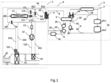
- the embodiment of this disclosure provides a vehicle thermal management system, specifically with reference to Fig.1 to Fig.4 .
- the vehicle thermal management system provided by this embodiment includes an air-conditioning refrigerating-heating loop 1, a battery thermal management loop 2, and an electric-drive thermal management loop 3.
- a battery cooler 4 is arranged between the air-conditioning refrigerating-heating loop 1 and the battery thermal management loop 2.
- a battery 21 is arranged in the battery thermal management loop 2.
- the electric-drive thermal management loop 3 includes an electric-drive coolant main path 6 and a heat-dissipation main path 7 which are sequentially connected in series.
- An electric drive assembly 31 is arranged in the electric-drive coolant main path 6.
- a radiator 32 is arranged in the heat-dissipation main path 7.
- the vehicle thermal management system further includes a thermoelectric heat exchanger 5.
- the thermoelectric heat exchanger 5 is disposed between the battery thermal management loop 2 and the electric-drive coolant main path 6 of the electric-drive thermal management loop 3, to regulate a heat transferring state of a coolant between the battery thermal management loop 2 and the electric-drive thermal management loop 3 via the thermoelectric heat exchanger 5.
- the electric-drive thermal management loop 3 further includes a heat-dissipation bypass 33 and an electric-drive-flow-path switch component 34.
- the heat-dissipation bypass 33 and the heat-dissipation main path 7 are connected in parallel.
- the electric-drive-flow-path switch component 34 is connected between one end of the heat-dissipation main path 7, one end of the heat-dissipation bypass 33 and one end of the electric-drive coolant main path 6. Wherein, after the electric-drive coolant main path 6 selectively communicates with the heat-dissipation main path 7 or the heat-dissipation bypass 33 by the electric-drive-flow-path switch component 34, a loop is formed.
- thermoelectric heat exchanger 5 by disposing the thermoelectric heat exchanger 5 between the battery thermal management loop 2 and the electric-drive thermal management loop 3, the thermoelectric heat exchanger 5, as a primary heat pump, can absorb heat in the electric drive assembly 31, the battery 21, and the environment.
- the battery cooler 4 is disposed between the air-conditioning refrigerating-heating loop 1 and the battery thermal management loop 2.
- the air-conditioning refrigerating-heating loop 1 can absorb the heat from the thermoelectric heat exchanger 5 by the battery cooler 4, and the compressor 12 of the air-conditioning refrigerating-heating loop 1 then can heat the passenger compartment, as a secondary heat pump.
- the compressor 12 can absorb heat in the electric drive assembly 31, the battery 21, and the environment, so that it may not fail due to over-heating or stop due to frost.
- the heat-dissipation bypass 33 in the electric-drive thermal management loop 3, there is no need to connect the radiator 32 when the environment temperature is relatively low or there is no need to absorb heat from the environment, thereby avoiding a problem that, the heat generated by the electric drive assembly 31 is conducted to the environment, thereby causing a waste, or that, the relatively low temperature of the coolant in the electric-drive thermal management loop 3 causes a reduced working efficiency of the electric drive assembly 31.
- the air-conditioning refrigerating-heating loop 1 includes a compressor flow path 121, an in-vehicle condenser flow path 141, a heating flow path 181, a refrigerant main path 41, a bypass-valve flow path 171, a function-valve flow path 191, a regulate-valve flow path 1111, and an in-vehicle evaporator flow path 152.
- the compressor flow path 121 is connected in series with the in-vehicle condenser flow path 141.
- the heating flow path 181 is connected in series with the compressor flow path 121.
- the refrigerant main path 41 is connected in parallel with the in-vehicle evaporator flow path 152 and the heating flow path 181.
- the refrigerant main path 41 includes an outdoor-heat-exchanger flow path 411 and a battery-cooler flow path 412 which are connected in series.
- the air-conditioning refrigerating-heating loop 1 further includes an outdoor heat exchanger 11, a compressor 12, a gas-liquid separator 13, an in-vehicle condenser 14, and an in-vehicle evaporator 15.
- the outdoor heat exchanger 11 has two modes.
- a heating mode the outdoor heat exchanger 11 can be equivalent to an evaporator, and the refrigerant evaporates inside the outdoor heat exchanger 11 and absorbs heat from the environment, thereby changing the refrigerant from a low-temperature and low-pressure liquid to a low-temperature and low-pressure gas.
- a refrigerating mode the outdoor heat exchanger 11 can be equivalent to a condenser, and the refrigerant condenses inside the outdoor heat exchanger 11 and releases heat, thereby changing the refrigerant from a high-temperature and high-pressure gas to a medium-temperature and high-pressure liquid.
- the outdoor heat exchanger 11 is disposed in the outdoor-heat-exchanger flow path 411. Further, one end of the outdoor-heat-exchanger flow path 411 communicates with the other end of the regulate-valve flow path 1111, and the other end of the outdoor-heat-exchanger flow path 411 communicates with one end of the heating flow path 181 and one end of the in-vehicle evaporator flow path 152.
- the gas-liquid separator 13 and the compressor 12 are disposed in series in the compressor flow path 121.
- the compressor 12 is disposed between the gas-liquid separator 13 and the in-vehicle condenser 14.
- the gas-liquid separator 13 is used to separate gas and liquid, so that the gas enters the compressor 12 and the liquid remains in an internal cavity of the gas-liquid separator 13.
- the compressor 12 is a driving power for the refrigerant cycle, which can change the low-temperature and low-pressure refrigerant gas into a high-temperature and high-pressure refrigerant gas.
- the in-vehicle condenser 14 is connected with the other end of the compressor flow path 121 and one end of the in-vehicle condenser flow path 141.
- the in-vehicle condenser 14 can condense the high-temperature and high-pressure refrigerant gas outputted from the compressor 12 into a medium-temperature and high-pressure refrigerant liquid, and release heat during the condensation to heat the air in the passenger compartment.
- the in-vehicle evaporator 15 is disposed in the in-vehicle evaporator flow path 152. And, the other end of the in-vehicle evaporator flow path 152 is connected with the other end of the heating flow path 181 and one end of the compressor flow path 121.
- the in-vehicle evaporator 15 can change the refrigerant from a low-temperature and low-pressure liquid to a low-temperature and low-pressure gas, and absorb the heat during the evaporation of the refrigerant to reduce the temperature of the air in the passenger compartment.
- the battery cooler 4 is disposed in the battery-cooler flow path 412 of the refrigerant main path 41. Further, the other end of the refrigerant path main 41 is connected with one end of the compressor flow path 121.
- the battery cooler 4 may be equivalent to an evaporator.
- the heat exchange medium of the battery cooler 4 includes the refrigerant of the air-conditioning refrigerating-heating loop 1, and the coolant of the battery thermal management loop 2. The refrigerant evaporates in the battery cooler 4 and absorbs the heat of the coolant, such that the coolant is cooled down and then the cooled-down coolant dissipates the heat of the battery.
- the air-conditioning refrigerating-heating loop 1 further includes a first regulate valve 111, a second regulate valve 16, a third regulate valve 151, a bypass valve 17, a heating valve 18, and a function valve 19.
- the first regulate valve 111, the second regulate valve 16, and the third regulate valve 151 are all used to regulate a flow rate of the refrigerant.
- the bypass valve 17, the heating valve 18, and the function valve 19 are all used to regulate a flow direction of the refrigerant.
- the first regulate valve 111 is disposed in the regulate-valve flow path 1111, on the side of one end of the outdoor heat exchanger 11.
- the second regulate valve 16 is disposed in the battery-cooler flow path 412 of the refrigerant main path 41, on the side of one end of the battery cooler 4.
- the third regulate valve 151 is disposed in the in-vehicle evaporator flow path 152, on the side of one end of the in-vehicle evaporator 15.
- the bypass valve 17 is disposed in the bypass-valve flow path 171.
- the bypass valve 17 is disposed with the first regulate valve 111 in parallel.
- one end of the bypass-valve flow path 171 is connected to one end of the first regulate valve 111, and the other end thereof is connected to the other end of the first regulate valve 111.
- the heating valve 18 is disposed in the heating flow path 181.
- One end of the heating flow path 181 is connected with the outdoor heat exchanger 11, and the other end of the heating flow path 181 is connected with one end of the compressor flow path 121.
- the function valve 19 is disposed in the function-valve flow path 191.
- One end of the function-valve flow path 191 is connected with the other end of the in-vehicle condenser flow path 141, and the other end of the function-valve flow path 191 is connected with one end of the battery-cooler flow path 412 of the refrigerant main path 41.
- first regulate valve 111, the second regulate valve 16, and the third regulate valve 151 all are electronic expansion valves. An opening degrees of the electronic expansion valves can be actively controlled, so they have a function of regulating a flow rate.
- the first regulate valve 111, the second regulate valve 16, and the third regulate valve 151 all can change the refrigerant from a medium-temperature and high-pressure refrigerant liquid into a low-temperature and low-pressure refrigerant liquid.
- the bypass valve 17, the heating valve 18, and the function valve 19 all are solenoid switch valves, which can regulate a flow direction of the refrigerant by opening and closing the solenoid switch valves.
- the principle of the air-conditioning refrigerating-heating loop 1 will be illustrated below in conjunction with Fig.1 .
- the air-conditioning refrigerating-heating loop 1 in this embodiment is mainly used for a thermal management of the passenger compartment, which has dual functions of heating the passenger compartment and refrigerating the passenger compartment.
- the high-temperature and high-pressure refrigerant gas outputted by the compressor 12 is first transmitted to the in-vehicle condenser 14 through the compressor flow path 121. Since it is the heating demand in the passenger compartment at this time, the air passes through the in-vehicle condenser 14 to exchange heat with the in-vehicle condenser 14, and releases heat to heat the passenger compartment. After becoming a medium-temperature and high-pressure liquid, the refrigerant passes through the in-vehicle condenser flow path 141 and the regulate-valve flow path 1111 sequentially, and to the outdoor heat exchanger 11.
- the outdoor heat exchanger 11 evaporates and absorbs the heat from the environment, such that the refrigerant becomes a low-temperature and low-pressure gas. After outputted from the outdoor heat exchanger 11, the refrigerant, in the form of low-temperature and low-pressure gas, passes through the heating flow path 181 and returns to the compressor flow path 121. After outputted from the outdoor heat exchanger 11, the refrigerant, in the form of low-temperature and low-pressure gas, can further passes through the second regulate valve 16 and the battery-cooler flow path 412 to the battery cooler 4, and absorbs heat from the coolant, thereby becoming a low-temperature and low-pressure gas and returning to the compressor flow path 121.
- the high-temperature and high-pressure refrigerant gas outputted by the compressor 12 is first transmitted to the in-vehicle condenser 14 through the compressor flow path 121. Since it is the refrigerating demand in the passenger compartment at this time, the air does not pass through the in-vehicle condenser 14 and does not exchange heat with the in-vehicle condenser 14. Instead, it passes through the in-vehicle condenser flow path 141 and the regulate-valve flow path 1111 sequentially, and to the outdoor heat exchanger 11 where it is condensed to a medium-temperature and high-pressure liquid.
- the liquid refrigerant can be throttled via the third regulate valve 151 on the side near one end of the in-vehicle evaporator 15 in the in-vehicle evaporator flow path 152, thereby becoming the low-temperature and low-pressure refrigerant liquid, and the heat of the air in the air-conditioner box is absorbed by the in-vehicle evaporator 15, thereby cooling down the air to refrigerating the passenger compartment.
- the liquid refrigerant can further flow through the outdoor-heat-exchanger flow path 411 and be throttled via the second regulate valve 16 on the side near one end of the battery cooler 4, thereby becoming the low-temperature and low-pressure refrigerant liquid, and the heat of the coolant is absorbed by the battery cooler 4 such that the coolant is cooled down so as to cool the battery 21.
- one end of the compressor flow path 121 described in this embodiment is an inlet of the compressor flow path 121, and the other end of the compressor flow path 121 is an outlet of the compressor flow path 121.
- One end of the in-vehicle condenser flow path 141 is an inlet of the in-vehicle condenser flow path 141, and the other end of the in-vehicle condenser flow path 141 is an outlet of the in-vehicle condenser flow path 141.
- One end of the in-vehicle evaporator flow path 152 is an inlet of the in-vehicle evaporator flow path 152, and the other end of the in-vehicle evaporator flow path 152 is an outlet of the in-vehicle evaporator flow path 152.
- One end of the heating flow path 181 is an inlet of the heating flow path 181, and the other end of the heating flow path 181 is an outlet of the heating flow path 181. So do other flow paths, that is, one end is an inlet for the refrigerant, and the other end is an outlet for the refrigerant. They are not listed one by one herein.
- the outdoor heat exchanger 11 in the air-conditioning refrigerating-heating loop 1, which functions as an evaporator when the passenger compartment has a heating demand, and function as a condenser when the passenger compartment has a refrigerating demand, thus controlling the temperature of the passenger compartment by varying the temperature and state of the refrigerant.
- disposing only one component can achieve the dual functions of refrigerating and heating, with higher integration and lower cost.
- a battery cooler 4 is arranged between the air-conditioning refrigerating-heating loop 1 and the battery thermal management loop 2.
- the battery cooler 4 has no essential difference in structure from a battery cooler 4 in the prior art, and its principle has been described in detail in the air-conditioning refrigerating-heating loop 1, which will not be repeated in this embodiment.
- the battery 21 is arranged in the battery thermal management loop 2.
- the structure of the battery 21 also belongs to the prior art, which will not be repeated in this embodiment.
- the battery thermal management loop 2 includes a battery coolant main path 8 and a battery flow path 9 which are sequentially connected in series.
- the thermoelectric heat exchanger 5 and the battery cooler 4 both are disposed on the battery coolant main path 8, and the battery 21 is disposed on the battery flow path 9.
- the battery thermal management loop 2 further includes a battery bypass 22 and a battery-flow-path switch component 23.
- the battery bypass 22 is connected in parallel with the battery coolant main path 8.
- the battery-flow-path switch component 23 is connected between the other end of the battery coolant main path 8, one end of the battery bypass 22, and one end of the battery flow path 9.
- the battery bypass 22 is a short bypass.
- a battery-loop water pump 24 is further arranged in the battery coolant main path 8, and the battery-loop water pump 24 is disposed between the thermoelectric heat exchanger 5 and the battery-flow-path switch component 23.
- the battery-loop water pump 24 mainly functions to regulate the flow direction of the coolant in the battery thermal management loop 2. Therefore, the one ends and the other ends of the battery coolant main path 8, the battery bypass 22, and the battery flow path 9 do not simply represent outlets and inlets of the battery coolant main path 8, the battery bypass 22, and the battery flow path 9.
- the one ends of the battery coolant main path 8, the battery bypass 22, and the battery flow path 9 are inlets of the battery coolant main path 8, the battery bypass 22, and the battery flow path 9, and, the other ends of the battery coolant main path 8, the battery bypass 22, and the battery flow path 9 are outlets of the battery coolant main path 8, the battery bypass 22, and the battery flow path 9.
- the regulation direction by the battery-loop water pump 24 is a second direction opposite to the first direction, the situation is the opposite.
- the battery-flow-path switch component 23 is a three-way valve which has a first port a, a second port b, and a third port c.
- the first port a is connected with the other end of the battery coolant main path 8.
- the second port b is connected with one end of the battery bypass 22, and the third port c is connected with one end of the battery flow path 9.
- the principle of the battery thermal management loop 2 will be illustrated below in conjunction with Fig.1 .
- the battery thermal management loop 2 in this embodiment is mainly used for thermal management of the battery 21, which functions to cool down the battery 21, and to transfer the heat of the electric-drive thermal management loop 3 to the air-conditioning refrigerating-heating loop 1.
- the refrigerant in the battery cooler 4 absorbs the heat of the coolant in the battery cooler 4, to cool down the coolant in the battery thermal management loop 2.
- the cooled coolant then cools the battery 21, to control the temperature of the coolant for the battery in the range of 15 °C ⁇ 2 5 °C.
- thermoelectric heat exchanger 5 also operates, and the side of the thermoelectric heat exchanger 5 contacting with the battery thermal management loop 2 is a refrigerating side, which is capable of further lowering the temperature of the coolant in the battery thermal management loop 2, to cool down the battery.
- the coolant flows through the battery bypass 22 and does not flow through the battery 21, so as to prevent the temperature of the coolant from being too low to affect the working efficiency of the battery 21.
- thermoelectric heat exchanger 5 also operates, and the side of the thermoelectric heat exchanger 5 contacting with the battery thermal management loop 2 is a heating side, which is capable of heating the coolant in the battery thermal management loop 2.
- the thermoelectric heat exchanger 5 can use the environment temperature or a waste heat from the electric drive assembly 31 to heat the battery 21, or transfer it to the air-conditioning refrigerating-heating loop 1 via the battery thermal management loop 2.
- the electric-drive thermal management loop 3 includes an electric-drive coolant main path 6 and a heat-dissipation main path 7 which are sequentially connected in series.
- An electric drive assembly 31 is arranged in the electric-drive coolant main path 6.
- a radiator 32 is arranged in the heat-dissipation main path 7.
- the electric drive assembly 31 includes a motor 311, and a charger 312.
- the electric drive assembly 31 is also an object of thermal management.
- the electric drive assembly 31 can be thermally managed by heating or cooling down the coolant of the electric-drive thermal management loop 3, according to actual needs.
- the radiator 32 is mainly used to realize heat exchange of the coolant with the environment. When the coolant temperature is higher than the environment temperature, the heat shifts from the coolant to the environment. When the coolant temperature is lower than the environment temperature, the heat shifts from the environment to the coolant.
- the electric-drive thermal management loop 3 further includes a heat-dissipation bypass 33 and an electric-drive-flow-path switch component 34.
- the heat-dissipation bypass 33 and the heat-dissipation main path 7 are connected in parallel.
- the electric-drive-flow-path switch component 34 is connected between one end of the heat-dissipation main path 7, one end of the heat-dissipation bypass 33 and one end of the electric-drive coolant main path 6. After the electric-drive coolant main path 6 selectively communicates with the heat-dissipation main path 7 or the heat-dissipation bypass 33 by the electric-drive-flow-path switch component 34, a loop is formed.
- the heat-dissipation bypass 33 is a short bypass.
- the heat-dissipation bypass 33 in the electric-drive thermal management loop 3, there is no need to connect the radiator 32 when the environment temperature is relatively low or there is no need to absorb heat from the environment, thereby avoiding a problem that, the heat generated by the electric drive assembly 31 is conducted to the environment, thereby causing a waste, or that, the relatively low temperature of the coolant in the electric-drive thermal management loop 3 causes a reduced working efficiency of the electric drive assembly 31.
- the electric-drive coolant main path 6 includes a thermoelectric-heat-exchange flow path 61 and an electric-drive flow path 62 which are sequentially connected in series.
- the thermoelectric heat exchanger 5 is disposed in the thermoelectric-heat-exchange flow path 61.
- the electric drive assembly 31 is disposed in the electric-drive flow path 62.
- the other end of the thermoelectric-heat-exchange flow path 61 is one end of the electric-drive coolant main path 6, and is connected with the electric-drive-flow-path switch component 34.
- the electric-drive thermal management loop further includes a thermoelectric-heat-exchange bypass 37.
- One end of the thermoelectric-heat-exchange bypass 37 is connected with one end of the thermoelectric-heat-exchange flow path 61, and the other end of the thermoelectric-heat-exchange bypass 37 is connected with the electric-drive-flow-path switch component 34, so that the thermoelectric-heat-exchange bypass 37 and the thermoelectric-heat-exchange flow path 61 are disposed in parallel.
- the electric-drive-flow-path switch component 34 selectively brings the heat-dissipation main path 7 or the heat-dissipation bypass 33 communicate with the thermoelectric-heat-exchange flow path 61 or the thermoelectric-heat-exchange bypass 37 and subsequently communicate with the electric-drive flow path 62, to form a loop.
- thermoelectric-heat-exchange bypass 37 by disposing the thermoelectric-heat-exchange bypass 37, when the thermoelectric heat exchanger 5 is not energized, the coolant flows through the thermoelectric-heat-exchange bypass 37 and does not flow through the thermoelectric heat exchanger 5. As a result, the thermoelectric heat exchanger 5 can be easily repaired and replaced. Even if the thermoelectric heat exchanger 5 malfunctions, the thermoelectric-heat-exchange bypass 37 can be temporarily used to ensure a flow in the loop, and maintain a basic refrigerating or heating demand, thereby improving a stability of the system.
- the electric-drive-flow-path switch component 34 is a four-way valve.
- the four-way valve has a first port a, a second port b, a third port c, and a fourth port d.
- the first port a is connected with one end of the heat-dissipation main path 7.
- the second port b is connected with the other end of the thermoelectric-heat-exchange flow path 61.
- the third port c is connected with the other end of the thermoelectric-heat-exchange bypass 37.
- the fourth port d is connected with one end of the heat-dissipation bypass 33.
- An electric-drive-loop water pump 35 is further arranged in the electric-drive flow path 62, and the electric-drive-loop water pump 35 is disposed between the thermoelectric heat exchanger 5 and the electric drive assembly 31.
- the four-way valve is a solenoid valve, which controls different flow paths in the electric-drive thermal management loop 3 to form a loop, by controlling opening-closure of any two ports of the first port a, the second port b, the third port c, and the fourth port d.
- the heat-dissipation main path 7 or the heat-dissipation bypass 33 communicates with the thermoelectric-heat-exchange flow path 61 or the thermoelectric-heat-exchange bypass 37, and subsequently communicates with the electric-drive flow path 62, to form a loop.
- the heat-dissipation main path 7 communicates with the thermoelectric-heat-exchange flow path 61.
- the heat-dissipation main path 7 communicates with the thermoelectric-heat-exchange bypass 37.
- thermoelectric-heat-exchange flow path 61 communicates with the heat-dissipation bypass 33.
- thermoelectric-heat-exchange bypass 37 communicates with the heat-dissipation bypass 33.
- the electric-drive coolant main path 6 includes a thermoelectric-heat-exchange flow path 61 and an electric-drive flow path 62 which are sequentially connected in series.
- the thermoelectric heat exchanger 5 is disposed in the thermoelectric-heat-exchange flow path 61.
- the electric drive assembly 31 is disposed in the electric-drive flow path 62.
- the other end of the thermoelectric-heat-exchange flow path 61 is one end of the electric-drive coolant main path 6, and is connected with the electric-drive-flow-path switch component 34.
- One end of the electric-drive flow path 62 is the other end of the electric-drive coolant main path 6, and is connected with the other end of the heat-dissipation main path 7, and the other end of the heat-dissipation bypass 33.
- An electric-drive-loop water pump 35 and a heat-exchange three-way valve 36 are further arranged in the thermoelectric-heat-exchange flow path 61.
- the electric-drive-loop water pump 35 and the heat-exchange three-way valve 36 are connected in series. Further, the electric-drive-loop water pump 35 is disposed between the heat-exchange three-way valve 36 and the thermoelectric heat exchanger 5.
- the electric-drive thermal management loop further includes an electric-drive bypass 38.
- One end of the electric-drive bypass 38 is connected with the heat-exchange three-way valve 36, and the other end of the electric-drive bypass 38 is connected with the heat-dissipation bypass 33, so that the electric-drive bypass 38 and the electric-drive flow path 62 are disposed in parallel.
- the heat-exchange three-way valve 36 has a first port x, a second port y, and a third port z.
- the first port x of the heat-exchange three-way valve 36 is connected with the electric-drive-loop water pump 35.
- the second port y of the heat-exchange three-way valve 36 is connected with the other end of the electric-drive flow path 62.
- the third port z of the heat-exchange three-way valve 36 is connected with one end of the electric-drive bypass 38.
- the thermoelectric-heat-exchange flow path 61 communicates with the electric-drive flow path 62.
- the thermoelectric-heat-exchange flow path 61 communicates with the electric-drive bypass 38.
- the electric-drive-flow-path switch component 34 is a three-way valve.
- the three-way valve has a first port a, a second port b, and a third port c.
- the first port a of the three-way valve is connected with one end of the heat-dissipation main path 7.
- the second port b of the three-way valve is connected with the other end of the thermoelectric-heat-exchange flow path 61.
- the third port c of the three-way valve is connected with one end of the heat-dissipation bypass 33.
- thermoelectric-heat-exchange flow path 61 communicates with the heat-dissipation bypass 33.
- the coolant flows through the heat-dissipation main path 7, the thermoelectric-heat-exchange flow path 61, and the electric-drive bypass, but does not flow through the electric-drive flow path 62.
- each of the heat-exchange three-way valve 36 and the electric-drive-flow-path switch component 34 is a solenoid valve.
- the electric-drive coolant main path 6 includes a thermoelectric-heat-exchange flow path 61 and an electric-drive flow path 62 which are sequentially connected in series.
- the thermoelectric heat exchanger 5 is disposed on the thermoelectric-heat-exchange flow path 61.
- the electric drive assembly 31 is disposed on the electric-drive flow path 62.
- the other end of the thermoelectric-heat-exchange flow path 61 is one end of the electric-drive coolant main path 6, and is connected with the electric-drive-flow-path switch component 34.
- One end of the electric-drive flow path 62 is the other end of the electric-drive coolant main path 6, and is connected with the other end of the heat-dissipation main path 7, and the other end of the heat-dissipation bypass 33.
- An electric-drive-loop water pump 35 and a heat-exchange three-way valve 36 are further arranged in the thermoelectric-heat-exchange flow path 61.
- the electric-drive-loop water pump 35 and the heat-exchange three-way valve 36 are connected in series. Further, the electric-drive-loop water pump 35 is disposed between the heat-exchange three-way valve 36 and the thermoelectric heat exchanger 5.
- the electric-drive thermal management loop further includes a thermoelectric-heat-exchange bypass 37 and an electric-drive bypass 38.
- One end of the thermoelectric-heat-exchange bypass 37 is connected with the electric-drive-loop water pump 35, and the other end of the thermoelectric-heat-exchange bypass 37 is connected with the electric-drive-flow-path switch component 34, so that the thermoelectric-heat-exchange bypass 37 and the thermoelectric heat exchanger 5 are disposed in parallel.
- One end of the electric-drive bypass 38 is connected with the heat-exchange three-way valve 36, and the other end of the electric-drive bypass 38 is connected with the electric-drive-flow-path switch component 34, so that the electric-drive bypass 38 and the electric-drive flow path 62 are disposed in parallel.
- the heat-exchange three-way valve 36 has a first port x, a second port y, and a third port z.
- the first port x of the heat-exchange three-way valve 36 is connected with the electric-drive-loop water pump 35.
- the second port y of the heat-exchange three-way valve 36 is connected with the other end of the electric-drive flow path 62.
- the third port z of the heat-exchange three-way valve 36 is connected with one end of the electric-drive bypass 38.
- the thermoelectric-heat-exchange flow path 61 communicates with the electric-drive flow path 62.
- the thermoelectric-heat-exchange flow path 61 communicates with the electric-drive bypass 38.
- the electric-drive-flow-path switch component 34 includes a first three-way valve and a second three-way valve which are connected in series.
- the first three-way valve and the second three-way valve both have a first port, a second port, and a third port.
- the first port a of the first three-way valve is connected with one end of the heat-dissipation main path 7.
- the second port b of the first three-way valve is connected with the other end of the thermoelectric-heat-exchange flow path 61.
- the third port c of the first three-way valve is connected with the first port d of the second three-way valve.
- the second port e of the second three-way valve is connected with the other end of the thermoelectric-heat-exchange bypass 37 and the other end of the electric-drive bypass 38.
- the third port f of the second three-way valve is connected with one end of the heat-dissipation bypass 33. Specifically, when the first port a of the first three-way valve communicates with the second port b of the first three-way valve, and the second port e of the second three-way valve communicates with the third port f of the second three-way valve, the heat-dissipation main path 7 communicates with the heat-dissipation bypass.
- the heat-dissipation main path 7 communicates with the thermoelectric-heat-exchange bypass 37, and the electric-drive flow path 62.
- the coolant flows through the heat-dissipation bypass 33, the heat-dissipation main path 7, the thermoelectric-heat-exchange flow path 61 and the electric-drive bypass 38, but does not flow through the electric-drive flow path 62.
- each of the first three-way valve and the second three-way valve both are solenoid valves.
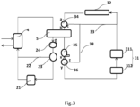
- the principle of the electric-drive thermal management loop 3 will be illustrated below in conjunction with Fig.1 , Fig.3 , and Fig.4 .
- the electric-drive thermal management loop 3 in this embodiment is mainly used for thermal management of the battery 31, and heat transferring of the environment and the battery thermal management loop 2.
- the coolant can pass through the radiator 32 to absorb heat from the environment, and then transmit the heat from the environment to the battery thermal management loop 2 via the thermoelectric heat exchanger 5. Furthermore, the heat generated by the electric drive assembly 31 can further be transmitted to the battery thermal management loop 2 via the thermoelectric heat exchanger 5.
- the radiator 32 cannot absorb heat from the environment. At this time, the radiator 32 can be bypassed, so that the temperature of the electric drive assembly 31 is transmitted to the battery thermal management loop 2.
- the heat in the battery thermal management loop 2 can be dissipated into the environment via the radiator 32 of the electric-drive thermal management loop 3.
- the electric-drive-loop water pump 35 mainly functions to regulate a flow direction of the coolant in the electric-drive thermal management loop 3. Therefore, one ends and other ends of the electric-drive coolant main path 6, the heat-dissipation main path 7, and the heat-dissipation bypass 33 do not simply represent outlets and inlets of the electric-drive coolant main path 6, the heat-dissipation main path 7, and the heat-dissipation bypass 33.
- the one ends of the electric-drive coolant main path 6, the heat-dissipation main path 7, and the heat-dissipation bypass 33 are inlets of the electric-drive coolant main path 6, the heat-dissipation main path, and the heat-dissipation bypass 33, and the other ends of the electric-drive coolant main path 6, the heat-dissipation main path 7, and the heat-dissipation bypass 33 are outlets of the electric-drive coolant main path 6, the heat-dissipation main path 7, and the heat-dissipation bypass 33.
- the regulation direction of the electric-drive-loop water pump 35 is a second direction opposite to the first direction, the situation is the opposite.
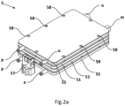
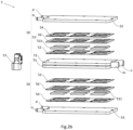
- thermoelectric heat exchanger 5 Next, with reference to Fig. 1 , Fig.2a and Fig.2b , the thermoelectric heat exchanger 5 will be illustrated.
- thermoelectric heat exchanger 5 is disposed between the battery thermal management loop 2 and the electric-drive coolant main path 6 of the electric-drive thermal management loop 3, to regulate a heat transferring state of the coolant between the battery thermal management loop 2 and the electric-drive thermal management loop 3 by the thermoelectric heat exchanger 5.
- the thermoelectric heat exchanger 5 causes the heat exchange between the battery thermal management loop 2 and the electric-drive thermal management loop 3.
- the refrigerating and heating of the thermoelectric heat exchanger 5 can be reversed, so that the heat can be transferred from the battery thermal management loop 2 to the electric-drive thermal management loop 3, and the heat can also be transferred from the electric-drive thermal management loop 3 to the battery thermal management loop 2.
- the reversion of refrigerating and heating of the thermoelectric heat exchanger 5 can be realized by converting positive and negative poles of a power supply.
- the thermoelectric heat exchanger 5 includes a thermoelectric heat exchange unit 50.
- the thermoelectric heat exchange unit 50 includes a battery liquid-cooling module 51, a thermoelectric module, and an electric-drive liquid-cooling module 55, which are sequentially stacked along a thickness direction of the thermoelectric heat exchanger 5.
- One side of the thermoelectric module contacts with the battery liquid-cooling module 51, and the other side of the thermoelectric module contacts with the electric-drive liquid-cooling module 55.
- the battery liquid-cooling module 51 is disposed in the battery thermal management loop 2, and is disposed in series with the battery 21.
- the electric-drive liquid-cooling module 55 is disposed in the electric-drive coolant main path 6, and is disposed in series with the electric drive assembly 31.
- a connector 57 is further arranged on a side face of the thermoelectric heat exchange unit 50, so as to facilitate connecting multiple thermoelectric heat exchange units 50 to form a thermoelectric heat exchanger 5 with a larger volume.
- mounting holes 58 are arranged at edges of the battery liquid-cooling module 51 and the electric-drive liquid-cooling module 55, for completing an installation and connection between a semiconductor layer, a thermally-conductive layer, a battery liquid-cooling module 51, and the electric-drive liquid-cooling module 55.
- the thermoelectric module includes a first thermally-conductive layer 52, a semiconductor layer 53, and a second thermally-conductive layer 54, which are sequentially stacked along the thickness direction of the thermoelectric heat exchange unit 50.
- One side of the first thermally-conductive layer 52 contacts with the battery liquid-cooling module 51, and the other side of the first thermally-conductive layer 52 contacts with one side of the semiconductor layer 53.
- the other side of the semiconductor layer 53 contacts with one side of the second thermally-conductive layer 54.
- the other side of the second thermal-conductive layer 54 contacts with the electric-drive liquid-cooling module 55.
- the semiconductor layer 53 includes a plurality of semiconductors 531 arranged in a matrix. A plurality of semiconductors 531 arranged in a matrix are supported by a support frame 56, to form the semiconductor layer 53.
- the semiconductor layer 53 is used to generate heat after being energized, so as to heat the battery liquid-cooling module 51 and the electric-drive liquid-cooling module 55.
- Each of the battery liquid-cooling module 51 and the electric-drive liquid-cooling module 55 is a water-cooling plate.
- the first thermally-conductive layer 52 and the thermally-conductive layer 54 both are disposed for better heat transferring.
- thermoelectric heat exchanger 5 has two thermoelectric heat exchange units 50 which are are sequentially stacked in the thickness direction of the thermoelectric heat exchanger 5.
- the battery liquid-cooling module 51 of one of the thermoelectric heat exchange units 50 is disposed near the battery liquid-cooling module 51 of the other of the thermoelectric heat exchange units 50.
- a third thermally-conductive layer is further arranged between the battery liquid-cooling module 51 of the one of the thermoelectric heat exchange units 50 and the battery liquid-cooling module 51 of the other of the thermoelectric heat exchange units 50.
- a battery loop water inlet m and a battery loop water outlet n are further arranged at a side face of each battery liquid-cooling module 51.
- An electric-drive loop water inlet o and an electric-drive loop water outlet p are further arranged at a side face of each electric-drive liquid-cooling module 55.
- thermoelectric heat exchanger 5 a refrigerating side and a heating side of the thermoelectric heat exchanger 5 are changed, by changing energized positive and negative poles of the battery liquid-cooling module 51 and the electric-drive liquid-cooling module 55.
- the battery liquid-cooling module 51 is connected to the positive pole.
- the battery liquid-cooling module 51 is connected to the negative pole.
- thermoelectric heat exchanger 5 may further include three, four, or even more thermoelectric heat exchange units 50, which are sequentially stacked in the thickness direction of the thermoelectric heat exchanger 5.
- the numbers of the semiconductor layer 53 and the thermally-conductive layer can further be set according to actual needs on heat generation and heat conduction, which is not limited to this embodiment.
- the embodiment of this disclosure also provides a vehicle thermal management method. Furthermore, the vehicle thermal management method provided in this embodiment is suitable for the vehicle thermal management system described in the above embodiment. Specifically, with reference to Fig.5 , the vehicle thermal management method includes following steps:
- the core temperature of the battery is less than the preset second temperature threshold, or the water temperature of the electric drive assembly is greater than or equal to the preset third temperature threshold, it is judged whether the water temperature of the electric drive assembly is greater than or equal to the environment temperature.
- the vehicle thermal management system enters a second mode.
- the vehicle thermal management system enters a third mode.
- the startup information of the vehicle includes, but is not limited to, an engine rotating speed, a vehicle controller power-on information, and an engine temperature.
- the engine rotating speed is greater than zero, or the vehicle controller is powered on, or the engine temperature continuously rises, it indicates that the vehicle is started up.
- the state information of the vehicle can be acquired directly from a power management module of the vehicle.
- the state of vehicle is typically divided into two types, i.e., a driving state and a charging state.
- the charging state in turn can be subdivided into fast charging and slow charging.
- the state information of the battery includes, but is not limited to, a battery temperature
- the state information of the passenger compartment includes, but is not limited to, a temperature of the passenger compartment.
- a temperature of the passenger compartment For example, when the temperature of the battery is less than a preset temperature threshold of about 25°C, the battery needs to be heated. When the temperature of the battery is greater than the preset temperature threshold of about 45°C, the battery needs to be cooled down.
- a air-conditioning temperature regulation button of the passenger compartment indicates “heating”, it shows that the passenger compartment needs to be heated. When the temperature regulation button of the passenger compartment indicates “refrigerating”, it shows that the passenger compartment needs to be cooled down.
- the step S4 can judge whether the thermal management demand of the vehicle is only heating the passenger compartment. In other words, there is no need to refrigerate or heat the battery at this time, but only to heat the passenger compartment.
- the core temperature and the water temperature of the electric drive assembly, etc. all can be collected by temperature sensors.
- a range of the preset first temperature threshold is -13°C to -17°C.
- it can be -13°C, -15°C, -16.5°C, -17°C, or other values within this range.
- a range of the preset second temperature threshold is 15°C to 25 °C.
- it can be 15° C, 20° C, 23.5° C, 25° C, or other values within this range.
- a range of the preset third temperature threshold is 0 °C to 10°C.
- it can be 0° C, 5° C, 7.5° C, 10° C, or other values within this range.
- Operating states of components of the vehicle thermal management system in the first mode, the second mode, and the third mode can refer to following table 1: Table 1 refrigerant side coolant side mode thermoelectric heat exchanger 3 rd regulate valve 1 st regulate valve 2 nd regulate valve bypass valve heating valve function valve battery-flow-path switch component electric-drive-flow-path switch component battery thermal management loop water pump electric-drive-loop water pump 1 st mode: winter: heating passenger compartment of ultra-low temperature (two stages of heat pumps + absorb heat stored in battery) not energized closed closed half-opened for throttling closed closed opened a&c in communication d&c in communication in operation in operation 2 nd mode: winter: heating passenger compartment (two stages of heat pumps + primary heat pump system absorbs heat from the motor) energized, battery side is hot side closed closed half-opened for throttling closed closed opened a&b in communication b&d in communication in operation in operation 3 rd mode: winter: heating passenger compartment of ultra-low temperature (two stages of heat pumps + primary heat pump absorb
- thermoelectric heat exchanger 5 in the first mode, the thermoelectric heat exchanger 5 is not energized.
- the battery-loop water pump 24 of the battery thermal management loop 2 operates, and the battery coolant main path 8 of the battery thermal management loop 2 communicates with the battery flow path 9.
- the electric-drive-loop water pump 35 of the electric-drive thermal management loop 3 operates, and the electric-drive-flow-path switch component 34 brings the electric-drive coolant main path 6 in communication with the heat-dissipation bypass 33, to form a loop.
- the compressor flow path 121, the in-vehicle condenser flow path 141, the function-valve flow path 191 and the battery-cooler flow path 412 of the air-conditioning refrigerating-heating loop 1 are in communication, to form a loop.
- the dotted line in the air-conditioning refrigerating-heating loop 1 represents a flow path through which the refrigerant does not pass
- the solid line represents a flow path through which the refrigerant passes.
- the arrow next to the solid line represents a flow direction of the refrigerant.
- the dotted lines in the battery thermal management loop 2 and the electric-drive thermal management loop 3 represent flow paths through which the coolant does not pass
- the solid line represents flow paths through which the coolant passes
- the arrow on the solid line indicates a flow direction of the coolant.
- the air-conditioning refrigerating-heating loop 1 further includes the first regulate valve 111, the second regulate valve 16, the third regulate valve 151, the bypass valve 17, the heating valve 18, and the function valve 19, in the first mode
- the first port a of the battery-flow-path switch component 23 communicates with the third port c of the battery-flow-path switch component 23
- the third port c of the electric-drive-flow-path switch component 34 communicates with the fourth port d of the electric-drive-flow-path switch component 34
- the first regulate valve 111 is closed
- the second regulate valve 16 is half-opened for throttling
- the third regulate valve 151 is closed
- the bypass valve 17 is closed
- the heating valve 18 is closed
- the function valve 19 is opened.
- the compressor 12 In the air-conditioning refrigerating-heating loop 1, the compressor 12 is in a heating mode.
- the high-temperature and high-pressure gas refrigerant out from the compressor 12 first passes through the in-vehicle condenser 14.
- the temperature damper of the air-conditioning box in the passenger compartment is in a fully-heating mode, and the air exchanges heat with the in-vehicle condenser 14, condenses and releases heat to heat the passenger compartment.
- the coolant cooled down by the battery cooler 4 enters the battery 21, and absorbs the heat stored in the battery 21.
- the heat of the passenger compartment is a sum of a power consumption amount of the compressor 12 and the heat of the battery 21 absorbed by the battery cooler 4.
- the electric-drive coolant main path 6 includes the thermoelectric-heat-exchange flow path 61 and the electric-drive flow path 62 which are sequentially connected in series
- the electric-drive thermal management loop 3 further includes the thermoelectric-heat-exchange bypass 37
- the electric-drive-flow-path switch component 34 brings the electric-drive flow path 62 in communication with the thermoelectric-heat-exchange bypass and the heat-dissipation bypass 33, to form a loop.
- the electric-drive-flow-path switch component 34 is a four-way valve
- the first port a of the four-way valve is connected with one end of the heat-dissipation main path 7
- the second port b is connected with the other end of the thermoelectric-heat-exchange flow path 61
- the third port c is connected with the other end of the thermoelectric-heat-exchange bypass 37
- the fourth port d is connected with one end of the heat-dissipation bypass 33
- the third port c and the fourth port d of the four-way valve are in communication.
- thermoelectric heat exchanger 5 in the second mode, the thermoelectric heat exchanger 5 is energized. Further, one side of the thermoelectric heat exchanger 5 located in the battery thermal management loop 2 is the heating side, and one side of the thermoelectric heat exchanger 5 located in the electric-drive thermal management loop 3 is the refrigerating side.
- the battery-loop water pump 24 of the battery thermal management loop 2 operates, and the battery coolant main path 8 and the battery bypass 22 of the battery thermal management loop 2 are in communication to form a loop.
- the electric-drive-loop water pump 35 of the electric-drive thermal management loop 3 operates, and the electric-drive-flow-path switch component 34 brings the electric-drive coolant main path 6 in communication with the heat-dissipation bypass 33, to form a loop.
- the compressor flow path 121, the in-vehicle condenser flow path 141, the function-valve flow path 191 and the battery-cooler flow path 412 of the air-conditioning refrigerating-heating loop 1 are in communication, to form a loop.
- the dotted line in the air-conditioning refrigerating-heating loop 1 represents a flow path through which the refrigerant does not pass
- the solid line represents a flow path through which the refrigerant passes.
- the arrow next to the solid line represents a flow direction of the refrigerant.
- the dotted lines in the battery thermal management loop 2 and the electric-drive thermal management loop 3 represent flow paths through which the coolant does not pass
- the solid line represents a flow path through which the coolant passes
- the arrow on the solid line indicates a flow direction of the coolant.
- the air-conditioning refrigerating-heating loop 1 further includes the first regulate valve 111, the second regulate valve 16, the third regulate valve 151, the bypass valve 17, the heating valve 18, and the function valve 19, in the second mode, the first port a and the second port b of the battery-flow-path switch component 23 are in communication, and the second port b and the fourth port d of the electric-drive-flow-path switch component 34 are in communication; the first regulate valve 111 is closed; the second regulate valve 16 is half-opened for throttling; the third regulate valve 151 is closed; the bypass valve 17 is closed; the heating valve 18 is closed; and the function valve 19 is opened.
- thermoelectric heat exchanger 5 is energized to operate for absorbing heat, as a supplement to the heat absorbed by the refrigerant of the battery cooler 4.
- the compressor 12 In the air-conditioning refrigerating-heating loop 1, the compressor 12 is in the heating mode.
- the high-temperature and high-pressure gas refrigerant out from the compressor 12 first passes through the in-vehicle condenser 14.
- the temperature damper of the air-conditioning box in the passenger compartment is in a fully-heating mode, and the air exchanges heat with the in-vehicle condenser 14, condenses and releases heat to heat the passenger compartment.
- the coolant bypasses the battery, thereby avoiding affecting the efficiency of the battery after the coolant temperature is lowered.
- the four-way valve bypasses the radiator.
- the heat of the electric drive assembly 31 is naturally conductively transferred to the side of the battery thermal management loop 2 through the thermoelectric heat exchanger 5, and then the heat is finally transferred to the passenger compartment through the loop for the refrigerant by the battery cooler 4.
- the heat of the passenger compartment is a sum of a power consumption of the compressor 12, a power consumption of the thermoelectric heat exchanger 5, and the heat absorbed by the thermoelectric heat exchanger 5 from the electric-drive thermal management loop 3.
- thermoelectric heat exchanger 5 in the third mode, the thermoelectric heat exchanger 5 is energized. Further, one side in the thermoelectric heat exchanger 5 located in the battery thermal management loop 2 is the heating side, and one side of the thermoelectric heat exchanger 5 located in the electric-drive thermal management loop 3 is the refrigerating side.
- the battery-loop water pump 24 of the battery thermal management loop 2 operates, and the battery coolant main path 8 and the battery bypass 22of the battery thermal management loop 2 are in communication to form a loop.
- the electric-drive-loop water pump 35 of the electric-drive thermal management loop 3 operates, and the electric-drive-flow-path switch component 34 brings the electric-drive coolant main path 6 in communication with the heat-dissipation main path 7, to form a loop.
- the compressor flow path 121, the in-vehicle condenser flow path 141, the function-valve flow path 191 and the battery-cooler flow path 412 of the air-conditioning refrigerating-heating loop 1 are in communication, to form a loop.
- the dotted line in the air-conditioning refrigerating-heating loop 1 represents a flow path through which the refrigerant does not pass
- the solid line represents a flow path through which the refrigerant passes.
- the arrow next to the solid line represents a flow direction of the refrigerant.
- the dotted lines in the battery thermal management loop 2 and the electric-drive thermal management loop 3 represent flow paths through which the coolant does not pass
- the solid line represents a flow path through which the coolant passes
- the arrow on the solid line indicates a flow direction of the coolant.
- the air-conditioning refrigerating-heating loop 1 further includes the first regulate valve 111, the second regulate valve 16, the third regulate valve 151, the bypass valve 17, the heating valve 18, and the function valve 19, in the third mode, the first port a and the second port b of the battery-flow-path switch component 23 are in communication; the first port a and the second port b of the electric-drive-flow-path switch component 34 are in communication; the first regulate valve 111 is closed; the second regulate valve 16 is half-opened for throttling; the third regulate valve 151 is closed; the by-pass valve 17 is closed; the heating valve 18 is closed; and the function valve 19 is opened.
- thermoelectric heat exchanger 5 is energized to operate for absorbing heat, as a supplement to the heat absorbed by the refrigerant of the battery cooler 4.
- the compressor 12 In the air-conditioning refrigerating-heating loop 1, the compressor 12 is in the heating mode.
- the high-temperature and high-pressure gas refrigerant out from the compressor 12 first passes through the in-vehicle condenser 14.
- the temperature damper of the air-conditioning box in the passenger compartment is in the fully-heating mode, and the air exchanges heat with the in-vehicle condenser 14, condenses and releases heat to heat the passenger compartment.
- the coolant bypasses the battery 21, thereby avoiding affecting the efficiency of the battery 21 after the coolant temperature is lowered.
- thermoelectric heat exchanger 5 In the electric-drive thermal management loop 3, the coolant cooled down by the thermoelectric heat exchanger 5 is lower than the environment temperature, and then absorbs the environment temperature by the radiator 32. The heating side of the thermoelectric heat exchanger 5 absorbs the heat from the environment and the heat is transferred to the electric-drive thermal management loop 3, and then to the battery thermal management loop 2 through the thermoelectric heat exchanger 5, and finally to the passenger compartment through the air-conditioning refrigerating-heating loop 1.
- the heat of the passenger compartment is a sum of a power consumption of the compressor 12, a power consumption of the thermoelectric heat exchanger 5, the heat absorbed by the radiator 32 from the environment, and the heat absorbed by the radiator 32 from the electric drive assembly 31.
- step S4 if the environment temperature is greater than or equal to the preset first temperature threshold, the vehicle thermal management system enters a fourth mode, and judges whether an outlet water temperature of the battery cooler is less than a sum of the temperature of the refrigerant at the other end of the outdoor heat exchanger of the air-conditioning refrigerating-heating loop and a preset first temperature difference threshold;
- openings of the first regulate valve and the second regulate valve of the vehicle thermal management system are regulated to a proportional limit, and it is judged whether the outlet water temperature of the electric drive assembly of the vehicle is greater than or equal to the environment temperature;
- the vehicle thermal management system enters a fifth mode.
- the vehicle thermal management system enters a sixth mode.
- a range of the preset first temperature difference threshold is 0°C to 5°C.
- it can be 0° C, 2.5° C, 5° C, or other values in this range.
- Operating states of components of the vehicle thermal management system in the fourth mode, the fifth mode, and the sixth mode can refer to following table 2: Table 2 refrigerant side coolant side mode thermoelectric heat exchanger 3 rd regulate valve 1 st regulate valve 2 nd regulate valve bypass valve heating valve function valve battery-flow-path switch component electric-drive-flow-path switch component battery thermal management loop water pump electric-drive -loop water pump 4 th mode: winter: heating passenger compartment (two stage of heat pumps absorb heat from environment + waste heat is recovered from motor) not energized closed half-opened for throttling half-opened for throttling closed opened opened a&b in communication b&d in communication, a&c not in communication in operation in operation 5 th mode: winter: heating passenger compartment (two stage of heat pumps absorb heat from environment +primary heat pump system absorbs heat from motor) energized, battery side is hot side closed half-opened for throttling half-opened for throttling closed opened opened a&b in communication b&d in communication in operation in operation 6
- thermoelectric heat exchanger 5 in the fourth mode, the thermoelectric heat exchanger 5 is not energized.
- the battery-loop water pump 24 of the battery thermal management loop 2 operates, and the battery coolant main path 8 and the battery bypass 22 of the battery thermal management loop 2 are in communication, to form a loop.
- the electric-drive-loop water pump 35 of the electric-drive thermal management loop 3 operates, and the electric-drive-flow-path switch component 34 brings the electric-drive coolant main path 6 in communication with the heat-dissipation bypass 33, to form a loop.
- the compressor flow path 121, the in-vehicle condenser flow path 141, the function valve flow path 191 and the battery-cooler flow path 412 of the air-conditioning refrigerating-heating loop 1 are in communication, to form a first loop.
- the compressor flow path 121, the in-vehicle condenser flow path 141, the outdoor-heat-exchanger flow path 411 and the heating flow path 181of the air-conditioning refrigerating-heating loop 1 are in communication, to form a second loop.
- the air-conditioning refrigerating-heating loop 1 further includes the first regulate valve 111, the second regulate valve 16, the third regulate valve 151, the bypass valve 17, the heating valve 18, and the function valve 19, in the fourth mode, the first port a and the second port b of the battery-flow-path switch component 23 are in communication, the second port b and the fourth port d of the electric-drive-flow-path switch component 34 are in communication; the first regulate valve 111 is half-opened for throttling; the second regulate valve 16 is half-opened for throttling; the third regulate valve 151 is closed; the bypass valve 17 is closed; the heating valve 18 is opened; and the function valve 19 is opened.
- the compressor 12 In the air-conditioning refrigerating-heating loop 1, the compressor 12 is in the heating mode.
- the high-temperature and high-pressure gas refrigerant out from the compressor 12 first passes through the in-vehicle condenser 14.
- the temperature damper of the air-conditioning box in the passenger compartment is in a fully-heating mode, and the air exchanges heat with the in-vehicle condenser 14, condenses and releases heat to heat the passenger compartment.
- the refrigerant is divided into two parts after the refrigerant becomes a medium-temperature and high-pressure liquid.
- One part after throttled by the first regulate valve 111, enters the outdoor heat exchanger 11 and evaporates to absorb the heat from the environment, such that the refrigerant becomes a low-temperature and low-pressure gas, passes through the heating valve 18 and returns to the compressor 12.
- the other part after throttled by the second regulate valve 16, passes through the function valve 19, enters the battery cooler 4 to absorb heat in the coolant, becomes a low-temperature and low-pressure gas, and returns to the compressor 12.
- the coolant bypasses the battery 21, thereby avoiding affecting the efficiency of the battery 21 after the coolant temperature is lowered.
- the radiator 32 is bypassed.
- the heat of the electric drive assembly 31 is naturally conductively transferred to the side of the battery thermal management loop 2 through the thermoelectric heat exchanger 5, and then the heat is finally transferred to the passenger compartment through the air-conditioning refrigerating-heating loop 1 by the battery cooler 4.
- the heat of the passenger compartment is a sum of a power consumption of the compressor 12, the heat absorbed by the outdoor heat exchanger 11, and the heat of the electric-drive thermal management loop 3 absorbed by the battery cooler 4.
- thermoelectric heat exchanger 1 in the fifth mode, the thermoelectric heat exchanger 1 is energized.
- One side of the thermoelectric heat exchanger 5 located in the battery thermal management loop 2 is the heating side
- one side of the thermoelectric heat exchanger 5 located at the electric-drive thermal management loop 3 is the refrigerating side.
- the battery-loop water pump 24 of the battery thermal management loop 2 operates, and the battery coolant main path 8 and the battery bypass 22 of the battery thermal management loop 2 are in communication, to form a loop.
- the electric-drive-loop water pump 35 of the electric-drive thermal management loop 3 operates, and the electric-drive-flow-path switch component 34 brings the electric-drive coolant main path 6 in communication with the heat-dissipation bypass 33, to form a loop.
- the compressor flow path 121, the in-vehicle condenser flow path 141, the function-valve flow path 191 and the battery-cooler flow path 412 of the air-conditioning refrigerating-heating loop 1 are in communication, to form a first loop.
- the compressor flow path 121, the in-vehicle condenser flow path 141, the outdoor-heat-exchanger flow path 411 and the heating flow path 181 of the air-conditioning refrigerating-heating loop 1 are in communication, to form a second loop.
- the air-conditioning refrigerating-heating loop 1 further includes the first regulate valve 111, the second regulate valve 16, the third regulate valve 151, the bypass valve 17, the heating valve 18, and the function valve 19, in the fifth mode, the first port a and the second port b of the battery-flow-path switch component 23 are in communication, the second port b and the fourth port d of the electric-drive-flow-path switch component 34 are in communication; the first regulate valve 111 is half-opened for throttling; the second regulate valve 16 is half-opened for throttling; the third regulate valve 151 is closed; the by-pass valve 17 is closed; the heating valve 18 is opened; and the function valve 19 is opened.
- thermoelectric heat exchanger 5 when the outlet water temperature of the battery cooler 4 is less than the temperature at outlet of the refrigerant of the outdoor heat exchanger 11, the system enters the fifth mode, and the thermoelectric heat exchanger 5 is energized to operate for absorbing heat, as a supplement to the heat absorbed by the refrigerant of the battery cooler 4.
- the compressor 12 In the air-conditioning refrigerating-heating loop 1, the compressor 12 is in the heating mode.
- the high-temperature and high-pressure gas refrigerant out from the compressor 12 first passes through the in-vehicle condenser 14.
- the temperature damper of the air-conditioning box in the passenger compartment is in a fully-heating mode, and the air exchanges heat with the in-vehicle condenser 14, condenses and releases heat to heat the passenger compartment.
- the refrigerant is divided into two parts after the refrigerant becomes a medium-temperature and high-pressure liquid.
- One part after throttled by the first regulate valve 111, enters the outdoor heat exchanger 11 and evaporates to absorb the heat from the environment, such that the refrigerant becomes a low-temperature and low-pressure gas, passes through the heating valve 18 and returns to the compressor 12.
- the other part after throttled by the second regulate valve 16, passes through the function valve 19, enters the battery cooler 4 to absorb heat in the coolant, becomes a low-temperature and low-pressure gas, and returns to the compressor 12.
- the coolant bypasses the battery 21, thereby avoiding affecting the efficiency of the battery 21 after the coolant temperature is lowered.
- the radiator 32 is bypassed.
- the heat of the electric drive assembly 31 is naturally conductively transferred to the side of the battery thermal management loop 2 through the thermoelectric heat exchanger 5, and then the heat is finally transferred to the passenger compartment through the air-conditioning refrigerating-heating loop 1 by the battery cooler 4.
- the heat of the passenger compartment is a sum of a power consumption of the compressor 12, the heat absorbed by the outdoor heat exchanger 11, a power consumption of the thermoelectric heat exchanger 5, and the heat absorbed by the thermoelectric heat exchanger 5 from the electric-drive thermal management loop 3.
- the difference between the fourth mode and the fifth mode is whether the thermoelectric heat exchanger 5 is energized.
- thermoelectric heat exchanger 1 in the sixth mode, the thermoelectric heat exchanger 1 is energized.
- One side of the thermoelectric heat exchanger 5 located in the battery thermal management loop 2 is the heating side
- one side of the thermoelectric heat exchanger 5 located in the electric-drive thermal management loop 3 is the refrigerating side.
- the battery-loop water pump 24 of the battery thermal management loop 2 operates, and the battery coolant main path 8 and the battery bypass 22 of the battery thermal management loop 2 are in communication, to form a loop.
- the electric-drive-loop water pump 35 of the electric-drive thermal management loop 3 operates, and the electric-drive-flow-path switch component 34 brings the electric-drive coolant main path 6 in communication with the heat-dissipation main path 7, to form a loop.
- the compressor flow path 121, the in-vehicle condenser flow path 141, the function-valve flow path 191 and the battery-cooler flow path 412 of the air-conditioning refrigerating-heating loop 1 are in communication, to form a first loop.
- the compressor flow path 121, the in-vehicle condenser flow path 141, the outdoor-heat-exchanger flow path 411 and the heating flow path 181 of the air-conditioning refrigerating-heating loop 1 are in communication, to form a second loop.
- the air-conditioning refrigerating-heating loop 1 further includes the first regulate valve 111, the second regulate valve 16, the third regulate valve 151, the bypass valve 17, the heating valve 18, and the function valve 19, in the sixth mode, the first port a and the second port b of the battery-flow-path switch component 23 are in communication, the first port a and the second port b of the electric-drive-flow-path switch component 34 are in communication; the first regulate valve 111 is half-opened for throttling; the second regulate valve 16 is half-opened for throttling; the third regulate valve 151 is closed; the bypass valve 17 is closed; the heating valve 18 is opened; and the function valve 19 is opened.
- thermoelectric heat exchanger 5 is energized to operate for absorbing heat, as a supplement to the heat absorbed by the refrigerant of the battery cooler 4.
- the compressor 12 In the air-conditioning refrigerating-heating loop 1, the compressor 12 is in the heating mode.
- the high-temperature and high-pressure gas refrigerant out from the compressor 12 first passes through the in-vehicle condenser 14.
- the temperature damper of the air-conditioning box in the passenger compartment is in a fully-heating mode, and the air exchanges heat with the in-vehicle condenser 14, condenses and releases heat to heat the passenger compartment.
- the refrigerant is divided into two parts after the refrigerant becomes a medium-temperature and high-pressure liquid.
- One part after throttled by the first regulate valve 111, enters the outdoor heat exchanger 11 and evaporates to absorb the heat from the environment, such that the refrigerant becomes a low-temperature and low-pressure gas, passes through the heating valve 18, and returns to the compressor 12.
- the other part after throttled by the second regulate valve 16, passes through the function valve 19, enters the battery cooler 4 to absorb heat in the coolant, becomes a low-temperature and low-pressure gas, and returns to the compressor 12.
- the coolant bypasses the battery 21, thereby avoiding affecting the efficiency of the battery 21 after the coolant temperature is lowered.
- thermoelectric heat exchanger 5 absorbs the environment temperature by the radiator 32.
- the heat side of the thermoelectric heat exchanger 5 absorbs the heat from the environment and the heat is transferred to the electric-drive thermal management loop 3, and then to the battery thermal management loop 2 through the thermoelectric heat exchanger 5, and finally to the passenger compartment through the air-conditioning refrigerating-heating loop 1.
- the heat of the passenger compartment is a sum of a power consumption of the compressor 12, the heat absorbed by the outdoor heat exchanger 11, a power consumption of the thermoelectric heat exchanger 5, the heat absorbed by the radiator 32 from the environment, and the heat absorbed by the thermoelectric heat exchanger 5 from the electric-drive thermal management loop 3.
- step S2 if the vehicle is currently in the driving state, the thermal management method further includes:
- the water temperature of the electric drive assembly is less than the preset fourth temperature threshold, it is judged whether the water temperature of the electric drive assembly is greater than or equal to the environment temperature.
- the vehicle thermal management system enters an eighth mode.
- the vehicle thermal management system enters a ninth mode.
- the state information of the battery and the state information of the passenger compartment here have no difference from the aforementioned state information of the battery and the state information of the passenger compartment, which do not be repeated here.
- a range of the preset third temperature threshold is 15°C to 25 °C.
- it can be 15° C, 17.5° C, 20° C, 25° C, or other values within this range.
- Operating states of components of the vehicle thermal management system in the seventh mode, the eighth mode, and the ninth mode can refer to following table 3: Table 3 refrigerant side coolant side mode thermoelectric heat exchanger 3 rd regulate valve 1 st regulate valve 2 nd regulate valve bypass valve heating valve function valve battery-flow-path switch component electric-drive-flow-path switch component battery thermal management loop water pump electric-drive-loop water pump 7 th mode: winter: heat from electric drive heats battery not energized normal normal normal normal normal normal normal normal normal normal a&c in communication b&d in communication in operation in operation 8 th mode: winter: primary heat pump absorb heat from motor to heat battery energized, battery side is hot side normal normal normal normal normal normal normal a&c in communication b&d in communication in operation in operation 9 th mode: winter: primary heat pump absorb heat from environment to heat battery energized, battery side is hot side normal normal normal normal normal normal normal a&c in communication a&b in communication in operation in operation in operation
- thermoelectric heat exchanger 1 in the seventh mode, the thermoelectric heat exchanger 1 is not energized.
- the battery-loop water pump 24 of the battery thermal management loop 2 operates, and the battery coolant main path 8 and the battery flow path 9 of the battery thermal management loop 2 are in communication, to form a loop.
- the electric-drive-loop water pump 35 of the electric-drive thermal management loop 3 operates, and the electric-drive-flow-path switch component 34 brings the electric-drive coolant main path 6 in communication with the heat-dissipation bypass 33, to form a loop.
- the air-conditioning refrigerating-heating loop 1 does not operate.
- the air-conditioning refrigerating-heating loop 1 further includes the first regulate valve 111, the second regulate valve 16, the third regulate valve 151, the by-pass valve 17, the heating valve 18, and the function valve 19, in the seventh mode, the first port a and the third port c of the battery-flow-path switch component 23 are in communication; the second port b and the fourth port d of the electric-drive-flow-path switch component 34 are in communicate; the first regulate valve 111 is in a normal state; the second regulate valve 16 is in a normal state; the third regulate valve 151 is in a normal state; the by-pass valve 17 is in a normal state; the heating valve 18 is in a normal state; and the function valve 19 is in a normal state.
- thermoelectric heat exchanger 5 does not operate, and the heat of the electric-drive thermal management loop 3 is naturally conductively transferred to the battery thermal management loop 2 through the thermoelectric heat exchanger 5.
- thermoelectric heat exchanger 1 is energized. Further, one side of the thermoelectric heat exchanger 5 located in the battery thermal management loop 2 is the heating side, and one side of the thermoelectric heat exchanger 5 located in the electric-drive thermal management loop 3 is the refrigerating side.
- the battery-loop water pump 24 of the battery thermal management loop 2 operates, and the battery coolant main path 8 and the battery flow path 9 of the battery thermal management loop 2 are in communication to form a loop.
- the electric-drive-loop water pump 35 of the electric-drive thermal management loop 3 operates, and the electric-drive-flow-path switch component 34 brings the electric-drive coolant main path 6 in communication with the heat-dissipation bypass 33, to form a loop.
- the air-conditioning refrigerating-heating loop 1 does not operate.
- the air-conditioning refrigerating-heating loop 1 further includes the first regulate valve 111, the second regulate valve 16, the third regulate valve 151, the bypass valve 17, the heating valve 18, and the function valve 19, in the eighth mode, the first port a and the third port c of the battery-flow-path switch component 23 are in communication; the first regulate valve 111 is in a normal state; the second regulate valve 16 is in a normal state; the third regulate valve 151 is in a normal state; the bypass valve 17 is in a normal state; the heating valve 18 is in a normal state; and the function valve 19 is in a normal state.
- thermoelectric heat exchanger 5 operates, and the heat absorption from the electric drive assembly 31 is enhanced by the thermoelectric heat exchanger 5.
- thermoelectric heat exchanger 1 in the ninth mode, the thermoelectric heat exchanger 1 is energized. Further, one side of the thermoelectric heat exchanger 5 located in the battery thermal management loop 2 is the heating side, and one side of the thermoelectric heat exchanger 5 located in the electric-drive thermal management loop 3 is the refrigerating side.
- the battery-loop water pump 24 of the battery thermal management loop 2 operates, and the battery coolant main path 8 and the battery flow path 9 of the battery thermal management loop 2 are in communication to form a loop.
- the electric-drive-loop water pump 35 of the electric-drive thermal management loop 3 operates, and the electric-drive-flow-path switch component 34 brings the electric-drive coolant main path 6 in communication with the heat-dissipation main path 7, to form a loop.
- the air-conditioning refrigerating-heating loop 1 does not operate.
- the air-conditioning refrigerating-heating loop 1 further includes the first regulate valve 111, the second regulate valve 16, the third regulate valve 151, the bypass valve 17, the heating valve 18, and the function valve 19, in the ninth mode, the first port a and the third port c of the battery-flow-path switch component 23 are in communication; the first port a and the second port b of the electric-drive-flow-path switch component 34 are in communication.; the first regulate valve 111 is in a normal state; the second regulate valve 16 is in a normal state; the third regulate valve 151 is in a normal state; the bypass valve 17 is in a normal state; the heating valve 18 is in a normal state; and the function valve 19 is in a normal state.
- thermoelectric heat exchanger 5 operates, and the heat absorption from the electric drive assembly 31 is enhanced by the thermoelectric heat exchanger 5.
- step S2 if the vehicle is currently in the driving state, the thermal management method further includes:
- the vehicle thermal management system enters a tenth mode.
- the vehicle thermal management system enters an eleventh mode.
- the target of heating the passenger compartment refers to whether the temperature of the passenger compartment reaches a preset minimum temperature.
- the preset minimum temperature may be manually input by a person in the passenger compartment.
- the preset rotating speed threshold is comprehensively defined according to the environment temperature, a setting for heating the passenger compartment, and a maximum value of a rotating speed of the compressor.
- Operating states of components of the vehicle thermal management system in the tenth mode and the eleventh mode can refer to following table 4: Table 4 refrigerant side coolant side mode thermoelectric heat exchanger 3 rd regulate valve 1 st regulate valve 2 nd regulate valve bypass valve heating valve function valve battery-flow-path switch component electric-drive-flow-path switch component battery thermal management loop water pump electric-drive-loop water pump 10 th mode: winter: heating passenger compartment +heating battery (two stage of heat pumps absorb heat from environment +primary heat pump system absorb heat from motor) energized, battery side is hot side closed half-opened for throttling half-opened for throttling closed opened opened a&c in communication b&d in communication in operation in operation 11 th mode: winter: heating passenger compartment + heating battery (two stage of heat pumps absorb heat from environment +primary heat pump system absorb heat from environment) energized, battery side is hot side closed half-opened for throttling half-opened for throttling closed opened opened a&c in communication a&b in communication in operation
- thermoelectric heat exchanger 1 in the tenth mode, the thermoelectric heat exchanger 1 is energized.
- One side of the thermoelectric heat exchanger 5 located in the battery thermal management loop 2 is the heating side
- one side of the thermoelectric heat exchanger 5 located in the electric-drive thermal management loop 3 is the refrigerating side.
- the battery-loop water pump 24 of the battery thermal management loop 2 operates, and the battery coolant main path 8 and the battery flow path 9 of the battery thermal management loop 2 are in communication, to form a loop.
- the electric-drive-loop water pump 35 of the electric-drive thermal management loop 3 operates, and the electric-drive-flow-path switch component 34 brings the electric-drive coolant main path 6 in communication with the heat-dissipation bypass 33, to form a loop.
- the compressor flow path 121, the in-vehicle condenser flow path 141, the function-valve flow path 191 and the battery-cooler flow path 412 of the air-conditioning refrigerating-heating loop 1 are in communication, to form a first loop.
- the compressor flow path 121, the in-vehicle condenser flow path 141, the outdoor-heat-exchanger flow path 411 and the heating flow path 181 of the air-conditioning refrigerating-heating loop 1 are in communication, to form a second loop.
- the air-conditioning refrigerating-heating loop 1 further includes the first regulate valve 111, the second regulate valve 16, the third regulate valve 151, the bypass valve 17, the heating valve 18, and the function valve 19, in the tenth mode, the first port a and the third port c of the battery-flow-path switch component 23 are in communication; the second port b and the fourth port d of the electric-drive-flow-path switch component 34 are in communication; the first regulate valve 111 is half-opened for throttling; the second regulate valve 16 is half-opened for throttling; the third regulate valve 151 is closed; the bypass valve 17 is closed; the heating valve 18 is opened; and the function valve 19 is opened.
- thermoelectric heat exchanger 1 in the eleventh mode, the thermoelectric heat exchanger 1 is energized.
- One side of the thermoelectric heat exchanger 5 located in the battery thermal management loop 2 is the heating side
- one side of the thermoelectric heat exchanger 5 located in the electric-drive thermal management loop 3 is the refrigerating side.
- the battery-loop water pump 24 of the battery thermal management loop 2 operates, and the battery coolant main path 8 and the battery flow path 9 of the battery thermal management loop 2 are in communication, to form a loop.
- the electric-drive-loop water pump 35 of the electric-drive thermal management loop 3 operates, and the electric-drive-flow-path switch component 34 brings the electric-drive coolant main path 6 in communication with the heat-dissipation main path 7, to form a loop.
- the compressor flow path 121, the in-vehicle condenser flow path 141, the function-valve flow path 191 and the battery-cooler flow path 412 of the air-conditioning refrigerating-heating loop 1 are in communication, to form a first loop.
- the compressor flow path 121, the in-vehicle condenser flow path 141, the outdoor-heat-exchanger flow path 411 and the heating flow path 181 of the air-conditioning refrigerating-heating loop 1 are in communication, to form a second loop.
- the air-conditioning refrigerating-heating loop 1 further includes the first regulate valve 111, the second regulate valve 16, the third regulate valve 151, the bypass valve 17, the heating valve 18, and the function valve 19, in the eleventh mode, the first port a and the third port c of the battery-flow-path switch component 23 are in communication; the first port a and the second port b of the electric-drive-flow-path switch component 34 are in communication; the first regulate valve 111 is half-opened for throttling; the second regulate valve 16 is half-opened for throttling; the third regulate valve 151 is closed; the bypass valve 17 is closed; the heating valve 18 is opened; and the function valve 19 is opened.
- step S1 if the vehicle is started up, the thermal management method further includes:
- a range of the preset fifth temperature threshold is -13 °C to -17°C.
- it can be -13 ° C,-15° C,-16.5° C,-17° C, or other values within this range.
- Operating states of components of the vehicle thermal management system in the twelfth mode and the thirteenth mode can refer to following table 5: Table 5 refrigerant side coolant side mode thermoelectric heat exchanger 3 rd regulate valve 1 st regulate valve 2 nd regulate valve bypass valve heating valve function valve battery-flow-path switch component electric-drive-path-flow switch component battery thermal management loop water pump electric-drive-loop water pump 12 th mode: winter: charging condition, heating battery, primary heat pump system heats battery energized, battery side is hot side normal normal normal normal normal normal normal a&c in communication a&b in communication in operation in operation 13 th mode: winter: charging condition, heating battery + heating passenger compartment energized, battery side is hot side closed closed half-opened for throttling closed closed opened a&c in communication a&b in communication in operation in operation in operation
- thermoelectric heat exchanger 5 in the twelfth mode, the thermoelectric heat exchanger 5 is energized. Further, one side of the thermoelectric heat exchanger 5 located in the battery thermal management loop 2 is the heating side, and one side of the thermoelectric heat exchanger 5 located in the electric-drive thermal management loop 3 is the refrigerating side.
- the battery-loop water pump 24 of the battery thermal management loop 2 operates, and the battery coolant main path 8 of the battery thermal management loop 2 communicates with the battery flow path 9 to form a loop.
- the electric-drive-loop water pump 35 of the electric-drive thermal management loop 3 operates, and the electric-drive-flow-path switch component 34 brings the electric-drive coolant main path 6 in communication with the heat-dissipation main path 7, to form a loop.
- the air-conditioning refrigerating-heating loop 1 does not operate, and the compressor 12 does not operate, either.
- the air-conditioning refrigerating-heating loop 1 further includes the first regulate valve 111, the second regulate valve 16, the third regulate valve 151, the bypass valve 17, the heating valve 18, and the function valve 19, in the twelfth mode, the first port a and the third port c of the battery-flow-path switch component 23 are in communication; the first port a and the second port b of the electric-drive-flow-path switch component 34 are in communication; the first regulate valve 111 is in a normal state; the second regulate valve 16 is in a normal state; the third regulate valve 151 is in a normal state; the bypass valve 17 is in a normal state; the heating valve 18 is in a normal state; and the function valve 19 is in a normal state.
- the air-conditioning refrigerating-heating loop 1 does not operate.
- the thermoelectric heat exchanger 5 operates, and heats the coolant at the side of the battery thermal management loop 2, to heat the battery 21.
- the thermoelectric heat exchanger 5 absorbs the heat from the environment through the electric-drive thermal management loop 3.
- a heat amount of heating the battery 21 is a sum of a power consumption of the thermoelectric heat exchanger 5 and the heat from the environment absorbed by the thermoelectric heat exchanger 5 through the electric-drive thermal management loop 3.
- thermoelectric heat exchanger 5 in the thirteenth mode, the thermoelectric heat exchanger 5 is energized. Further, one side of the thermoelectric heat exchanger 5 located in the battery thermal management loop 2 is the heating side, and one side of the thermoelectric heat exchanger 5 located in the electric-drive thermal management loop 3 is the refrigerating side.
- the battery-loop water pump 24 of the battery thermal management loop 2 operates, and the battery coolant main path 8 and the battery flow path 9 of the battery thermal management loop 2 are in communication to form a loop.
- the electric-drive-loop water pump 35 of the electric-drive thermal management loop 3 operates, and the electric-drive-flow-path switch component 34 brings the electric-drive coolant main path 6 in communication with the heat-dissipation main path 7, to form a loop.
- the compressor flow path 121, the in-vehicle condenser flow path 141, the function-valve flow path 191 and the battery-cooler flow path 412 of the air-conditioning refrigerating-heating loop 1 are in communication, to form a loop.
- the air-conditioning refrigerating-heating loop 1 further includes the first regulate valve 111, the second regulate valve 16, the third regulate valve 151, the bypass valve 17, the heating valve 18, and the function valve 19, in the thirteenth mode, the first port a and the third port c of the battery-flow-path switch component 23 are in communication; the first port a and the second port b of the electric-drive-flow-path switch component 34 are in communication; the first regulate valve 111 is closed; the second regulate valve 16 is half-opened for throttling; the third regulate valve 151 is closed; the bypass valve 17 is closed; the heating valve 18 is closed; and the function valve 19 is opened.
- the thirteenth mode is similar to the third mode.
- the operating states of the air-conditioning refrigerating-heating loop 1 and the electric-drive thermal management loop 3 are the same.
- the difference is that, in the battery thermal management loop 2 in the thirteenth mode, the coolant heated by the thermoelectric heat exchanger 5 first passes through the battery 21 to heat the battery 21, and then passes through the battery cooler 4.
- the coolant cooled down by the battery cooler 4 is then heated by the thermoelectric heat exchanger 5.
- the power consumption of the thermoelectric heat exchanger 5 in the thirteenth mode is greater.
- a sum of the heat in the passenger compartment and the heat amount of heating the battery 21 is a sum of a power consumption of the compressor 12, a power consumption of the thermoelectric heat exchanger 5, and the heat absorbed by the radiator 32 from the environment.
- step S1 if the vehicle is started up, the thermal management method further includes:
- the vehicle thermal management system enters a fifteenth mode.
- the vehicle thermal management system enters a seventeenth mode.
- a range of the preset sixth temperature threshold is 18°C to 22°C.
- it may be 18°C, 19.5°C, 20°C, 22°C, or other values in this range.
- a range of the preset seventh temperature threshold is 12°C to 20°C. For example, it may be 12° C, 15° C, 18.5° C, 20° C, or other values in this range.
- a range of the preset first temperature difference threshold is 0°C to 5°C.
- it can be 0° C, 2.5° C, 5° C, or other values in this range.
- Operating state of components of the vehicle thermal management system in the fourteenth mode, the fifteenth mode, and the sixteenth mode, and the seventeenth mode can refer to following table 6: Table 6 refrigerant side coolant side mode thermoelec tric heat exchanger 3 rd regulate valve 1 st regulate valve 2 nd regulate valve bypass valve heating valve function valve battery-flow-path switch component electric- drive-flow-path switch component battery thermal managem ent loop water pump electric-drive-loop water pump 14 th mode: summer: refrigerating passenger compartment (rapidly refrigerating) /thermoelectric heat exchanger cools battery energized, battery side is cold side opened opened closed/half-opened for throttling opened closed closed closed a&c in communication a&b in communication in operation in operation 15 th mode: summer: refrigerating passenger compartment, cooling battery, motor cooling mode not energized opened/ closed opened closed/half-opened for throttling opened closed closed closed a&c in communication a&c in communication in operation /closed in operation 16 th
- thermoelectric heat exchanger 5 in the fourteenth mode, the thermoelectric heat exchanger 5 is energized. Further, one side of the thermoelectric heat exchanger 5 located in the battery thermal management loop 2 is the refrigerating side, and one side of the thermoelectric heat exchanger 5 located in the electric-drive thermal management loop 3 is the heating side.
- the battery-loop water pump 24 of the battery thermal management loop 2 operates, and the battery coolant main path 8 of the battery thermal management loop 2 communicates with the battery flow path 9 to form a loop.
- the electric-drive-loop water pump 35 of the electric-drive thermal management loop 3 operates, and the electric-drive-flow-path switch component 34 brings the electric-drive coolant main path 6 in communication with the heat-dissipation main path 7, to form a loop.
- the compressor flow path 121, the in-vehicle condenser flow path 141, the regulate valve flow path 1111 and the indoor evaporator flow path of the air-conditioning refrigerating-heating loop 1 are in communication, to form a loop, and the refrigerant does not flow through the in-vehicle condenser 14.
- the air-conditioning refrigerating-heating loop 1 further includes the first regulate valve 111, the second regulate valve 16, the third regulate valve 151, the bypass valve 17, the heating valve 18, and the function valve 19, in the fourteenth mode, the first port a and the third port c of the battery-flow-path switch component 23 are in communication; the first port a and the second port b of the electric-drive-flow-path switch component 34 are in communication; the first regulate valve 111 is opened; the second regulate valve 16 is closed or half-opened for throttling; the third regulate valve 151 is opened; the bypass valve 17 is opened; the heating valve 18 is closed; and the function valve 19 is closed.
- thermoelectric heat exchanger 5 operates, cools down the coolant in the battery thermal management loop 2 to cool the battery 21, heats the coolant in the electric-drive thermal management loop 3, and then transfers the heat to the environment through the radiator 32.
- the high-temperature and high-pressure gas refrigerant out from the compressor 12 first passes through the in-vehicle condenser 14.
- the temperature damper of the air-conditioning box in the passenger compartment is in a fully-cooling mode.
- the air does not pass through the in-vehicle condenser 14, that is, the air does not exchange heat with the in-vehicle condenser 14, and then passes through the bypass valve 17, and enters the outdoor heat exchanger 11 to condense into a medium-temperature and high-pressure liquid.
- the refrigerant is one part, that is, it is throttled by the third regulate valve 151, and absorbs the heat of the air in the air-conditioning box through the in-vehicle evaporator 15 to cool down the air and cool the passenger compartment.
- thermoelectric heat exchanger 5 in the fifteenth mode, the thermoelectric heat exchanger 5 is not energized.
- the battery-loop water pump 24 of the battery thermal management loop 2 operates or turns off, and the battery coolant main path 8 and the battery flow path of the battery thermal management loop 2 are in communication to form a loop.
- the electric-drive-loop water pump 35 of the electric-drive thermal management loop 3 operates, and the electric-drive-flow-path switch component 34 brings the electric-drive coolant main path 6 in communication with the heat-dissipation main path 7, to form a loop.
- the compressor flow path 121, the bypass valve flow path 171, the function-valve flow path 191, the outdoor-heat-exchanger flow path 411, and the battery-cooler flow path 412 of the air conditioning refrigerating-heating loop 1 are in communication to form a first loop.
- the compressor flow path 121, the in-vehicle condenser flow path 141, the bypass-valve flow path 171, the function valve flow path 191, the outdoor heat exchanger and the in-vehicle evaporator flow path 152 of the air-conditioning refrigerating-heating loop 1 are in communication, to form a second loop.
- the air-conditioning refrigerating-heating loop 1 further includes the first regulate valve 111, the second regulate valve 16, the third regulate valve 151, the bypass valve 17, the heating valve 18, and the function valve 19, in the fifteenth mode, the first port a and the third port c of the battery-flow-path switch component 23 are in communication; the first port a and the third port c of the electric-drive-flow-path switch component 34 are in communication; the first regulate valve 111 is opened; the second regulate valve 16 is closed or half-opened for throttling; the third regulate valve 151 is opened or closed; the bypass valve 17 is opened; the heating valve 18 is closed; and the function valve 19 is closed.
- the electric-drive coolant main path 6 includes the thermoelectric-heat-exchange flow path 61 and the electric-drive flow path 62, which are sequentially connected in series
- the electric-drive thermal management loop 3 further includes the thermoelectric-heat-exchange bypass 37, in the fifteenth mode
- the electric-drive-flow-path switch component 34 brings the electric-drive flow path 62, the thermoelectric-heat-exchange bypass 37 in communication with the heat-dissipation main path 7, to form a loop.
- the electric-drive-flow-path switch component 34 is a four-way valve
- the first port a of the four-way valve is connected with one end of the heat-dissipation main path 7
- the second port b is connected with the other end of the thermoelectric-heat-exchange flow path 61
- the third port c is connected with the other end of the thermoelectric-heat-exchange bypass 37
- the fourth port d is connected with one end of the heat-dissipation bypass 33
- the first port a and third port c of the four-way valve are in communication.
- the battery thermal management loop 2 is independent of the electric-drive thermal management loop 3.
- the thermoelectric heat exchanger 5 does not operate.
- the coolant in the electric-drive thermal management loop 3 does not pass through the thermoelectric heat exchanger 5.
- the electric-drive thermal management loop 3 drives the coolant to pass through the radiator 32 by the electric-drive-loop water pump 35, to dissipate the heat.
- the cooled coolant cools an object to be cooled of the electric-drive thermal management loop 3.
- the target water temperature for cooling of the electric-drive thermal management loop 3 is typically less than or equal to 65°C.
- the battery thermal management loop 2 absorbs the heat of the coolant in the battery cooler 4 by the refrigerant in the battery cooler 4, to cool down the coolant of the battery thermal management loop 2.
- the cooled-down coolant then cools the battery 21.
- a target water temperature of the coolant of the battery thermal management loop 2 is typically 15 ⁇ 25°C.
- the high-temperature and high-pressure gas refrigerant out from the compressor 12 first passes through the in-vehicle condenser 14.
- the temperature damper of the air-conditioning box in the passenger compartment is in fully-cooling mode.
- the air does not pass through the in-vehicle condenser 14, that is, the air does not exchange heat with the in-vehicle condenser 14, and then passes through the bypass valve 17, and enters the outdoor heat exchanger 11 to condense into a medium-temperature and high-pressure liquid.
- the refrigerant is divided into two parts. One part is throttled by the third regulate valve 151 in front of the air-conditioning box.
- the other part is throttled by the second regulate valve 16 in front of the battery cooler 4, and becomes a low-temperature and low-pressure liquid after throttled.
- the in-vehicle evaporator 15 absorbing the heat of air in the air-conditioning box, the air is cooled down to cool the passenger compartment.
- the battery cooler 4 absorbing the heat of the coolant, the coolant is cooled down to cool the battery 21.
- thermoelectric heat exchanger 5 in the sixteenth mode, the thermoelectric heat exchanger 5 is not energized.
- the battery-loop water pump 24 of the battery thermal management loop 2 operates, and the battery cooler 4 of the battery thermal management loop 2 does not operate.
- the electric-drive-loop water pump 35 of the electric-drive thermal management loop 3 operates, and the electric-drive-flow-path switch component 34 brings the electric-drive coolant main path 6 in communication with the heat-dissipation main path 7, to form a loop.
- the operating state of the air-conditioning refrigerating-heating loop 1 is to be determined.
- the air-conditioning refrigerating-heating loop 1 further includes the first regulate valve 111, the second regulate valve 16, the third regulate valve 151, the bypass valve 17, the heating valve 18, and the function valve 19, in the sixteenth mode, the first port a and the third port c of the battery-flow-path switch component 23 are in communication; the first port a and the second port b of the electric-drive-flow-path switch component 34 are in communication; the first regulate valve 111 is to be determined; the second regulate valve 16 is to be determined; the third regulate valve 151 is to be determined; the bypass valve 17 is to be determined; the heating valve 18 is to be determined; and the function valve 19 is to be determined.
- the environment temperature is relatively low, for example, less than 20°C.
- the battery 21 has a cooling demand, and the battery 21 can be cooled by the radiator 32, and the compressor 12 and the battery cooler 4 do not need to operate.
- thermoelectric heat exchanger 5 in the seventeenth mode, the thermoelectric heat exchanger 5 is energized. Further, one side of the thermoelectric heat exchanger 6 located in the battery thermal management loop 2 is the refrigerating side, and one side of the thermoelectric heat exchanger 5 located at the electric-drive thermal management loop 3 is the heating side.
- the battery cooler 4 of the battery thermal management loop 2 does not operate, and the electric-drive-loop water pump 35 of the electric-drive thermal management loop 3 operates.
- the electric-drive-flow-path switch component 34 brings the electric-drive coolant main path 6 in communication with the heat-dissipation main path 7, to form a loop.
- the operating state of the air-conditioning refrigerating-heating loop 1 is to be determined.
- the air-conditioning refrigerating-heating loop 1 further includes the first regulate valve 111, the second regulate valve 16, the third regulate valve 151, the bypass valve 17, the heating valve 18, and the function valve 19, in the seventeenth mode, the first port a and the third port c of the battery-flow-path switch component 23 are in communication; the first port a and the second port b of the electric-drive-flow-path switch component 34 are in communication; the first regulate valve 111 is to be determined; the second regulate valve 16 is to be determined; the third regulate valve 151 is to be determined; the bypass valve 17 is to be determined; the heating valve 18 is to be determined; and the function valve 19 is to be determined.
- thermoelectric heat exchanger 5 may assist the operation.
- the thermoelectric heat exchanger 5 cools down the coolant of the battery thermal management loop 2 to cool the battery 21, heats the coolant of the electric-drive thermal management loop 3, and then transfers the heat to the environment through the radiator 32.
- the target water temperature of the battery 21 is typically 12°C to 20°C.
Landscapes
- Engineering & Computer Science (AREA)
- Mechanical Engineering (AREA)
- Physics & Mathematics (AREA)
- Thermal Sciences (AREA)
- Transportation (AREA)
- Power Engineering (AREA)
- Life Sciences & Earth Sciences (AREA)
- Sustainable Development (AREA)
- Sustainable Energy (AREA)
- Chemical & Material Sciences (AREA)
- Combustion & Propulsion (AREA)
- Air-Conditioning For Vehicles (AREA)
Abstract
Description
- This disclosure relates to a technical field of thermal management of new energy vehicles, and in particular to a vehicle thermal management system and a vehicle thermal management method.
- In recent years, with the gradual popularity of new energy vehicles, respective performances of a new energy vehicle have also been significantly improved. A thermal management system of a new energy vehicle is a system that manages heat of the new energy vehicle, and the operation of the thermal management system also has a great impact on cruising range of the new energy vehicle. In order to make the cruising range of the new energy vehicle longer and longer, the requirements on the thermal management system of the new energy vehicle are getting higher and higher.
- The thermal management system of the new energy vehicle usually consists of three parts. The first part is a thermal management of a passenger compartment, which controls a temperature of the passenger compartment at 15°C-20°C and a humidity thereof at about 50%-60%, so as to meet needs of passengers. The second part is a thermal management of a battery, which controls a working temperature of the battery at 25°C-45°C. The third part is a thermal management of a drive assembly which mainly includes heating elements such as a drive motor, a voltage-stabilized power supply and a motor controller. The goal for the thermal management of the drive assembly is to control the coolant temperature below 65°C.
- In prior art, for the thermal management of the passenger compartment, a water-side high-voltage electric heater is typically disposed on a water side or an air-side high-voltage electric heater is disposed on an air side. However, a heating efficiency of each of the both ways is very low. For the thermal management of the battery, a water-side high-voltage electric heater is added into a battery loop to warm a coolant at a low temperature, but the heating efficiency of this way is also very low.
- In order to improve the heating efficiency, some of vehicles have added a heat pump system to the thermal management system based on a refrigerant cycle. In traditional heat pump systems, environment heat is absorbed by a refrigerant evaporating inside an outdoor heat exchanger. Specifically, the refrigerant throttled via an expansion valve becomes a low-temperature and low-pressure liquid and enters the outdoor heat exchanger, and the temperature of the refrigerant is required to be lower than the environment temperature. A property of the refrigerant is that, as a degree of throttling is greater and the low pressure is lower, the corresponding refrigerant temperature is lower. For example, when the environment temperature is lower than -15°C, the refrigerant temperature is required to be lower than about -20°C such that the heat can be absorbed from the environment through the outdoor heat exchanger. When the refrigerant is lower than -20°C, an absolute pressure of the refrigerant is only 1.3 bar. When the refrigerant pressure is too low, the mass flow when an equal volume of refrigerant is sucked by a compressor may be greatly reduced, thereby resulting in a problem of the compressor being overheated and poor return of lubricating oil, which may cause failure of the compressor. In addition, since the temperature of the outdoor heat exchanger is lower than the environment temperature and the temperature difference therebetween is large, when the outdoor heat exchanger exchanges heat, a drop in air temperature may cause the water vapor in the air to condense and become frost attached onto the outdoor heat exchanger, which may result in a deterioration of a heat exchange capacity of the outdoor heat exchanger, thereby resulting in a deterioration of a performance of the heat pump system, and the heat pump system may stop when the frost has formed to a certain extent.
- Therefore, in the thermal management system in the prior art, when the temperature of the refrigerant is too low, the compressor is prone to fail due to over-heating. Furthermore, the heat pump system may further stop due to the frost, and a working efficiency is reduced.
- The object of this disclosure is to solve the problem of relatively low working efficiency of the thermal management system in the prior art.
- To solve the above problem, an embodiment of this disclosure discloses a vehicle thermal management system, comprising an air-conditioning refrigerating-heating loop, a battery thermal management loop, and an electric-drive thermal management loop, a battery cooler is arranged between the air-conditioning refrigerating-heating loop and the battery thermal management loop, a battery is arranged in the battery thermal management loop, the electric-drive thermal management loop comprises an electric-drive coolant main path and a heat-dissipation main path which are sequentially connected in series, an electric drive assembly is arranged in the electric-drive coolant main path, and a radiator is arranged in the heat-dissipation main path, the vehicle thermal management system further comprises a thermoelectric heat exchanger, the thermoelectric heat exchanger is disposed between the battery thermal management loop and the electric-drive coolant main path of the electric-drive thermal management loop, such that a heat transferring state of a coolant between the battery thermal management loop and the electric-drive thermal management loop is regulated by the thermoelectric heat exchanger; the electric-drive thermal management loop further comprises a heat-dissipation bypass and an electric-drive-flow-path switch component, the heat-dissipation bypass is connected in parallel with the heat-dissipation main path, and the electric-drive-flow-path switch component is connected between one end of the heat-dissipation main path, one end of the heat-dissipation bypass, and one end of the electric-drive coolant main path; wherein, a loop is formed after the electric-drive coolant main path selectively communicates with the heat-dissipation main path or the heat-dissipation bypass by the electric-drive-flow-path switch component.
- With the above solution, by disposing the thermoelectric heat exchanger between the battery thermal management loop and the electric-drive thermal management loop, the thermoelectric heat exchanger, as a primary heat pump, can absorb heat in the electric drive assembly, the battery, and the environment. The battery cooler is disposed between the air-conditioning refrigerating-heating loop and the battery thermal management loop, the air-conditioning refrigerating-heating loop can absorb heat of the thermoelectric heat exchanger by the battery cooler, and the compressor of the air-conditioning refrigerating-heating loop can heat the passenger compartment, as a secondary heat pump. As a result, even when the environment temperature is relatively low, the compressor can absorb heat in the electric drive assembly, the battery, and the environment, so that it may not fail due to over-heating or stop due to frost. Further, by disposing the heat-dissipation bypass in the electric-drive thermal management loop, the radiator may be not connected when the environment temperature is relatively low or there is no need to absorb heat from the environment, thereby avoiding the problem that, the heat generated by the electric drive assembly is conducted to the environment, thereby causing a waste, or the relatively low temperature of the coolant in the electric-drive thermal management loop causes a reduced working efficiency of the electric drive assembly.
- In addition, by heating the battery and the passenger compartment by the heat of the electric drive assembly, it is possible to effectively utilize the heat of the electric drive assembly, thereby improving a utilization rate of the heat. Further, the heat absorbed by the thermoelectric heat exchanger from the electric-drive heat management loop and the heat absorbed by the battery cooler from the air-conditioning refrigerating-heating loop both can be used to heat the battery, thereby improving a heating efficiency of the battery. Thus, there is no need to dispose a thermistor for heating (Positive Temperature Coefficient, PTC) in the air-conditioning refrigerating-heating loop and the battery thermal management loop, thereby reducing a cost of the system.
- According to another embodiment of this disclosure, in the vehicle thermal management system disclosed in the embodiment of this disclosure, the thermoelectric heat exchanger comprises a thermoelectric heat exchange unit, the thermoelectric heat exchange unit comprises a battery liquid-cooling module, a thermoelectric module, and an electric-drive liquid-cooling module, which are sequentially stacked along a thickness direction of the thermoelectric heat exchanger, one side of the thermoelectric module contacts with the battery liquid-cooling module, the other side of the thermoelectric module contacts with the electric-drive liquid-cooling module, the battery liquid-cooling module is disposed in the battery thermal management loop, and is disposed in series with the battery, and the electric-drive liquid-cooling module is disposed in the electric-drive coolant main path, and is disposed in series with the electric drive assembly.. Further, in some embodiments, the thermoelectric heat exchanger may have two thermoelectric heat exchange units, and the two thermoelectric heat exchange units are sequentially stacked in the thickness direction of the thermoelectric heat exchanger. The battery liquid-cooling module of one of the thermoelectric heat exchange units is disposed near the battery liquid-cooling module of the other one of the thermoelectric heat exchange units, and a third thermally-conductive layer is further arranged between the battery liquid-cooling module of the one of the thermoelectric heat exchange units and the battery liquid-cooling module of the other one of the thermoelectric heat exchange units.
- With the above solution, by integrating the battery liquid-cooling module, the thermoelectric module, and the electric-drive liquid-cooling module to form the thermoelectric heat exchanger, utilizing only one component can realize the heat transferring between the battery thermal management loop and the electric-drive thermal management loop, which causes a higher integration.
- According to another embodiment of this disclosure, in the vehicle thermal management system disclosed in the embodiment of this disclosure, the thermoelectric module comprises a first thermally-conductive layer, a semiconductor layer, and a second thermally-conductive layer, which are sequentially stacked along a thickness direction of the thermoelectric heat exchange unit; one side of the first thermally-conductive layer contacts with the battery liquid-cooling module, the other side of the first thermally-conductive layer contacts with one side of the semiconductor layer, the other side of the semiconductor layer contacts with one side of the second thermally-conductive layer, the other side of the second thermally-conductive layer contacts with the electric-drive liquid-cooling module, and the semiconductor layer comprises a plurality of semiconductors arranged in a matrix.
- With the above solution, the thermoelectric module is consisted of the thermally-conductive layers and the semiconductor layer. Since the semiconductor layer generates heat quickly, and the thermally-conductive layers can further transfer heat to the battery liquid-cooling module and the electric-drive liquid-cooling module, it is possible to improve a heat transferring efficiency of the thermoelectric heat exchanger.
- According to another embodiment of this disclosure, in the vehicle thermal management system disclosed in the embodiment of this disclosure, the electric-drive coolant main path comprises a thermoelectric-heat-exchange flow path and an electric-drive flow path which are sequentially connected in series, the thermoelectric heat exchanger is disposed in the thermoelectric-heat-exchange flow path, the electric drive assembly is disposed in the electric-drive flow path, the other end of the thermoelectric-heat-exchange flow path is the one end of the electric-drive coolant main path, and is connected with the electric-drive-flow-path switch component, and one end of the electric-drive flow path is the other end of the electric-drive coolant main path, and is connected with the other end of the heat-dissipation main loop and the other end of the heat-dissipation bypass; the electric-drive thermal management loop further comprises a thermoelectric-heat-exchange bypass, one end of the thermoelectric-heat-exchange bypass is connected with one end of the thermoelectric-heat-exchange flow path, and the other end of the thermoelectric-heat-exchange bypass is connected with the electric-drive-flow-path switch component, so that the thermoelectric-heat-exchange bypass and the thermoelectric-heat-exchange flow path are disposed in parallel; wherein, the electric-drive-flow-path switch component selectively brings the heat-dissipation main path or the heat-dissipation bypass in communication with the thermoelectric-heat-exchange flow path or the thermoelectric-heat-exchange bypass and subsequently in communication with the electric-drive flow path, to form a loop.
- With the above solution, by disposing the thermoelectric-heat-exchange bypass, when the thermoelectric heat exchanger is not energized, the coolant flows through the thermoelectric-heat-exchange bypass and does not flow through the thermoelectric heat exchanger. As a result, the thermoelectric heat exchanger can be easily repaired and replaced. Even if the thermoelectric heat exchanger malfunctions, the thermoelectric-heat-exchange bypass can be temporarily used to ensure a flow in the loop, and maintain a basic refrigerating or heating demand, thereby improving a stability of the system.
- According to another embodiment of this disclosure, in the vehicle thermal management system disclosed in the embodiment of this disclosure, the electric-drive-flow-path switch component is a four-way valve which has a first port, a second port, a third port, and a fourth port; the first port is connected with one end of the heat-dissipation main path, the second port is connected with the other end of the thermoelectric-heat-exchange flow path, the third port is connected with the other end of the thermoelectric-heat-exchange bypass, and the fourth port is connected with one end of the heat-dissipation bypass; an electric-drive-loop water pump is further arranged in the electric-drive flow path, and the electric-drive-loop water pump is disposed between the thermoelectric heat exchanger and the electric drive assembly.
- With the above solution, by disposing the four-way valve, a plurality of flow paths can be in communication to form a plurality of different loops with a simple component, and the configuration is simple.
- According to another embodiment of this disclosure, in the vehicle thermal management system disclosed in the embodiment of this disclosure, the electric-drive coolant main path comprises a thermoelectric-heat-exchange flow path and an electric-drive flow path which are sequentially connected in series, the thermoelectric heat exchanger is disposed in the thermoelectric-heat-exchange flow path, the electric drive assembly is disposed in the electric-drive flow path, the other end of the thermoelectric-heat-exchange flow path is the one end of the electric-drive coolant main path, and is connected with the electric-drive-flow-path switch component, and one end of the electric-drive flow path is the other end of the electric-drive coolant main path, and is connected with the other end of the heat-dissipation main path and the other end of the heat-dissipation bypass; an electric-drive-loop water pump and a heat-exchange three-way valve are further arranged in the thermoelectric-heat-exchange flow path, the electric-drive-loop water pump and the heat-exchange three-way valve are connected in series, and the electric-drive-loop water pump is disposed between the heat-exchange three-way valve and the thermoelectric heat exchanger; the electric-drive thermal management loop further comprises an electric-drive bypass, one end of the electric-drive bypass is connected with the heat-exchange three-way valve, and the other end of the electric-drive bypass is connected with the heat-dissipation bypass, so that the electric-drive bypass and the electric-drive flow path are disposed in parallel; the heat-exchange three-way valve has a first port, a second port, and a third port, the first port of the heat-exchange three-way valve is connected with the electric-drive-loop water pump, the second port of the heat-exchange three-way valve is connected with the other end of the electric-drive flow path, and the third port of the heat-exchange three-way valve is connected with one end of the electric-drive bypass; the electric-drive-flow-path switch component is a three-way valve which has a first port, a second port, and a third port; the first port of the three-way valve is connected with one end of the heat-dissipation main path, the second port of the three-way valve is connected with the other end of the thermoelectric-heat-exchange flow path, and the third port of the three-way valve is connected with one end of the heat-dissipation bypass.
- With the above solution, by disposing the electric-drive bypass, when the coolant temperature in the electric-drive thermal management loop is too low, the coolant flows through the electric-drive bypass and does not flow through the electric-drive flow path, avoiding the problem that the coolant temperature is too low to thus affect the operating efficiency of the battery .
- According to another embodiment of this disclosure, in the vehicle thermal management system disclosed in the embodiment of this disclosure, the electric-drive coolant main path comprises a thermoelectric-heat-exchange flow path and an electric-drive flow path which are sequentially connected in series, the thermoelectric heat exchanger is disposed in the thermoelectric-heat-exchange flow path, the electric drive assembly is disposed in the electric-drive flow path, the other end of the thermoelectric-heat-exchange flow path is the one end of the electric-drive coolant main path, and is connected with the electric-drive-flow-path switch component, and one end of the electric-drive flow path is the other end of the electric-drive coolant main path, and is connected with the other end of the heat-dissipation main loop and the other end of the heat-dissipation bypass; an electric-drive-loop water pump and a heat-exchange three-way valve are further arranged in the thermoelectric-heat-exchange flow path, the electric-drive-loop water pump and the heat-exchange three-way valve are connected in series, and the electric-drive-loop water pump is disposed between the heat-exchange three-way valve and the thermoelectric heat exchanger; the electric-drive thermal management loop further comprises a thermoelectric-heat-exchange bypass and an electric-drive bypass, one end of the thermoelectric-heat-exchange bypass is connected with the electric-drive-loop water pump, and the other end of the thermoelectric-heat-exchange bypass is connected with the electric-drive-flow-path switch component, so that the thermoelectric-heat-exchange bypass and the thermoelectric heat exchanger are disposed in parallel; one end of the electric-drive bypass is connected with the heat-exchange three-way valve, and the other end of the electric-drive bypass is connected with the electric-drive-flow-path switch component, so that the electric-drive bypass and the electric-drive-flow-path are disposed in parallel; the heat-exchange three-way valve has a first port, a second port, and a third port, the first port of the heat-exchange three-way valve is connected with the electric-drive-loop water pump, the second port of the heat-exchange three-way valve is connected with the other end of the electric-drive flow path, and the third port of the heat-exchange three-way valve is connected with one end of the electric-drive bypass; the electric-drive-flow-path switch component comprises a first three-way valve and a second three-way valve which are connected in series, the first three-way valve and the second three-way valve both have a first port, a second port, and a third port; the first port of the first three-way valve is connected with one end of the heat-dissipation main path, the second port of the first three-way valve is connected with the other end of the thermoelectric-heat-exchange flow path, and the third port of the first three-way valve is connected with the first port of the second three-way valve; the second port of the second three-way valve is connected with the other end of the thermoelectric-heat-exchange bypass and the other end of the electric-drive bypass, and the third port of the second three-way valve is connected with one end of the heat-dissipation bypass.
- According to another embodiment of this disclosure, in the vehicle thermal management system disclosed in the embodiment of this disclosure, the battery thermal management loop comprises a battery coolant main path and a battery flow path which are sequentially connected in series, the thermoelectric heat exchanger and the battery cooler both are disposed in the battery coolant main path, and the battery is disposed in the battery flow path; and the battery thermal management loop further comprises a battery bypass and a battery-flow-path switch component; the battery bypass and the battery coolant main path are connected in parallel, and the battery-flow-path switch component is connected between the other end of the battery coolant main path, one end of the battery bypass, and one end of the battery flow path; and the heat-dissipation bypass and the battery bypass both are short bypasses; a battery-loop water pump is further arranged in the battery coolant main path, and the battery-loop water pump is disposed between the thermoelectric heat exchanger and the battery-flow-path switch component.
- With the above solution, by disposing the battery bypass to bypass the battery flow path, and utilizing the battery-flow-path switch component to regulate a connection state of the battery bypass or the battery flow path, when the battery needs no refrigerating or the temperature of the refrigerant is relatively low, the coolant only flows through the battery bypass and does not flow through the battery flow path, which can avoid the problem that the coolant temperature is too low to thus affect the operating efficiency of the battery.
- According to another embodiment of this disclosure, in the vehicle thermal management system disclosed in the embodiment of this disclosure, the battery-flow-path switch component is a three-way valve which has a first port, a second port, and a third port, the first port is connected with the other end of the battery coolant main path, the second port is connected with one end of the battery bypass, and the third port is connected with one end of the battery flow path.
- With the above solution, by disposing the three-way valve, a plurality of flow paths can be in communication to form a plurality of different loops with a simple component, and the configuration is simple.
- According to another embodiment of this disclosure, in the vehicle thermal management system disclosed in the embodiment of this disclosure, the air-conditioning refrigerating-heating loop comprises a compressor flow path, an in-vehicle condenser flow path, a heating flow path, a refrigerant main path, a bypass-valve flow path, a function-valve flow path, a regulate-valve flow path, and an in-vehicle evaporator flow path; the compressor flow path is connected in series with the in-vehicle condenser flow path, the heating flow path is connected in series with the compressor flow path, the refrigerant main path is connected in parallel with the in-vehicle evaporator flow path and the heating flow path, and the refrigerant main path comprises an outdoor-heat-exchanger flow path and a battery-cooler flow path which are connected in series; and the air-conditioning refrigerating-heating loop further comprises an outdoor heat exchanger, a compressor, a gas-liquid separator, an in-vehicle condenser, and an in-vehicle evaporator; the outdoor heat exchanger is disposed in the outdoor-heat-exchanger flow path, and one end of the outdoor-heat-exchanger flow path communicates with the other end of the regulate-valve flow path, and the other end of the outdoor-heat-exchanger flow path communicates with one end of the heating flow path and one end of the in-vehicle evaporator flow path; the gas-liquid separator and the compressor are disposed in series in the compressor flow path; the in-vehicle condenser is connected with the other end of the compressor flow path and one end of the in-vehicle condenser flow path; the in-vehicle evaporator is disposed in the in-vehicle evaporator flow path, and the other end of the in-vehicle evaporator flow path is connected with the other end of the heating flow path and one end of the compressor flow path; the battery cooler is disposed in the battery-cooler flow path of the refrigerant main path, and the other end of the refrigerant main path is connected with one end of the compressor flow path; the air-conditioning refrigerating-heating loop further comprises a first regulate valve, a second regulate valve, a third regulate valve, a bypass valve, a heating valve, and a function valve; the first regulate valve, the second regulate valve, and the third regulate valve all are used to regulate a flow rate of the refrigerant; the bypass valve, the heating valve, and the function valve all are used to regulate a flow direction of the refrigerant; the first regulate valve is disposed in the regulate-valve flow path, and is located at the side of one end of the outdoor heat exchanger; the second regulate valve is disposed in the battery-cooler flow path of the refrigerant main path, and is located at the side of one end of the battery cooler; the third regulate valve is disposed in the in-vehicle evaporator flow path, and is located at the side of one end of the in-vehicle evaporator; the bypass valve is disposed in the bypass-valve flow path, the bypass valve is disposed in parallel with the first regulate valve, and one end of the bypass-valve flow path is connected to one end of the first regulate valve, and the other end is connected to the other end of the first regulate valve; the heating valve is disposed in the heating flow path, one end of the heating flow path is connected with the outdoor heat exchanger, and the other end of the heating flow path is connected with one end of the compressor flow path; the function valve is disposed in the function-valve flow path, one end of the function-valve flow path is connected with the other end of the in-vehicle condenser flow path, and the other end of the function-valve flow path is connected with one end of the battery-cooler flow path of the refrigerant main path.
- The embodiment of this disclosure also discloses a vehicle thermal management method, adapted for the vehicle thermal management system as described in any one of the above embodiments, the vehicle thermal management method includes following steps:
- S1: acquiring a startup information of a vehicle, and judging whether the vehicle is started up according to the startup information of the vehicle;
- if yes, step S2 is performed;
- if no, it is repeatedly judged whether the vehicle is started up;
- S2: acquiring a state information of the vehicle from a power management module of the vehicle, and judging whether the vehicle is currently in a driving state according to the state information of the vehicle;
- if the vehicle is currently in the driving state, step S3 is performed;
- if the vehicle is not currently in the driving state, it is repeatedly judged whether the vehicle is currently in the driving state;
- S3: acquiring a state information of a battery and a state information of a passenger compartment in the vehicle thermal management system, and judging whether a thermal management demand of the vehicle is only heating the passenger compartment according to the state information of the battery and the state information of the passenger compartment;
- if yes, step S4 is performed;
- if no, it is repeatedly judged whether the thermal management demand of the vehicle is only heating the passenger compartment;
- S4: judging whether an environment temperature is less than a preset first temperature threshold;
- if yes, it is judged whether a core temperature of the battery is greater than or equal to a preset second temperature threshold, and whether a water temperature of the electric drive assembly is less than a preset third temperature threshold;
- if the core temperature of the battery is greater than or equal to the preset second temperature threshold, and the water temperature of the electric drive assembly is less than the preset third temperature threshold, the vehicle thermal management system enters a first mode; wherein in the first mode, the thermoelectric heat exchanger is not energized, a battery-loop water pump of the battery thermal management loop operates, a battery coolant main path of the battery thermal management loop communicates with a battery flow path, an electric-drive-loop water pump of the electric-drive thermal management loop operates, and the electric-drive-flow-path switch component brings the electric-drive coolant main path in communication with the heat-dissipation bypass, to form a loop; a compressor flow path, an in-vehicle condenser flow path, a function-valve flow path and the battery-cooler flow path of the air-conditioning refrigerating-heating loop are in communication, to form a loop;
- if a core temperature of the battery is less than a preset second temperature threshold, or the water temperature of the electric drive assembly is greater than or equal to a preset third temperature threshold, it is judged whether the water temperature of the electric drive assembly is greater than or equal to the environment temperature;
- if the water temperature of the electric drive assembly is greater than or equal to the environment temperature, the vehicle thermal management system enters a second mode; wherein in the second mode, the thermoelectric heat exchanger is energized, and one side of the thermoelectric heat exchanger located in the battery thermal management loop is a heating side, and one side of the thermoelectric heat exchanger located in the electric-drive thermal management loop is a refrigerating side, the battery-loop water pump of the battery thermal management loop operates, the battery coolant main path and a battery bypass of the battery thermal management loop are in communication to form a loop; the electric-drive-loop water pump of the electric-drive thermal management loop operates, and the electric-drive-flow-path switch component brings the electric-drive coolant main path in communication with the heat-dissipation bypass, to form a loop; the compressor flow path, the in-vehicle condenser flow path, the function-valve flow path and the battery-cooler flow path of the air-conditioning refrigerating-heating loop are in communication, to form a loop;
- if the water temperature of the electric drive assembly is less than the environment temperature, the vehicle thermal management system enters a third mode; wherein in the third mode, the thermoelectric heat exchanger is energized, and one side of the thermoelectric heat exchanger located in the battery thermal management loop is a heating side, one side of the thermoelectric heat exchanger located in the electric-drive thermal management loop is a refrigerating side, the battery-loop water pump of the battery thermal management loop operates, the battery coolant main path and the battery bypass of the battery thermal management loop are in communication to form a loop; the electric-drive-loop water pump of the electric-drive thermal management loop operates, and the electric-drive-flow-path switch component brings the electric-drive coolant main path in communication with the heat-dissipation main path, to form a loop; the compressor flow path, the in-vehicle condenser flow path, the function-valve flow path and the battery-cooler flow path of the air-conditioning refrigerating-heating loop are in communication, to form a loop..
- With the above solution, when the environment temperature is relatively low, since the thermoelectric heat exchanger is disposed to absorb heat in the electric drive assembly and the environment, and can also heat the coolant in the battery thermal management loop and transfer heat to the air-conditioning refrigerating-heating loop. The compressor can absorb heat in the electric drive assembly, the battery, and the environment, even when the environment temperature is relatively low, so that it may not fail due to over-heating or stop due to frost. Further, the heat-dissipation bypass is arranged in the electric-drive thermal management loop, the radiator can be not connected when the environment temperature is relatively low or there is no need to absorb heat from the environment, thereby avoiding the problem that, the heat generated by the electric drive assembly is conducted to the environment, thereby causing a waste, or the relatively low temperature of the coolant in the electric-drive thermal management loop causes a reduced working efficiency of the electric drive assembly.
- According to another embodiment of this disclosure, in the vehicle thermal management method disclosed in the embodiment of this disclosure, while the electric-drive coolant main path comprises a thermoelectric-heat-exchange flow path and an electric-drive flow path which are sequentially connected in series, and the electric-drive thermal management loop further comprises a thermoelectric-heat-exchange bypass, in the first mode, the electric-drive-flow-path switch component brings the electric-drive flow path, the thermoelectric-heat-exchange bypass in communication with the heat-dissipation bypass, to form a loop; and when the electric-drive-flow-path switch component is a four-way valve, and a first port of the four-way valve is connected with one end of the heat-dissipation main path, a second port is connected with the other end of the thermoelectric-heat-exchange flow path, a third port is connected with the other end of the thermoelectric-heat-exchange bypass, and a fourth port is connected with one end of the heat-dissipation bypass, the third port and the fourth port of the four-way valve are in communication.
- With the above solution, the thermoelectric-heat-exchange bypass is disposed in the electric-drive heat management loop, and the coolant flows through the thermoelectric-heat-exchange bypass and does not flow through the thermoelectric heat exchanger when the thermoelectric heat exchanger is not energized. As a result, the thermoelectric heat exchanger can be easily repaired and replaced. Even if the thermoelectric heat exchanger malfunctions, the thermoelectric-heat-exchange bypass can be temporarily used to ensure a flow in the loop, maintain a basic refrigerating or heating demand, thereby improving a stability of the system.
- According to another embodiment of this disclosure, in the vehicle thermal management method disclosed in the embodiment of this disclosure, in the step S4,
- if the environment temperature is greater than or equal to the preset first temperature threshold, the vehicle thermal management system enters a fourth mode, and it is judged whether an outlet water temperature of the battery cooler is less than a sum of a temperature of refrigerant at the other end of the outdoor heat exchanger of the air-conditioning refrigerating-heating loop, and a preset first temperature difference threshold;
- if yes, opening degrees of a first regulate valve and a second regulate valve of the vehicle thermal management system are regulated to a proportional limit, and it is judged whether an outlet water temperature of the electric drive assembly of the vehicle is greater than or equal to the environment temperature;
- if the outlet water temperature of the electric drive assembly of the vehicle is greater than or equal to the environment temperature, the vehicle thermal management system enters a fifth mode;
- if the temperature of the electric drive assembly of the vehicle is less than the environment temperature, the vehicle thermal management system enters a sixth mode; wherein
- in the fourth mode, the thermoelectric heat exchanger is not energized, the battery-loop water pump of the battery thermal management loop operates, the battery coolant main path and the battery bypass of the battery thermal management loop are in communication, to form a loop; the electric-drive-loop water pump of the electric-drive thermal management loop operates, the electric-drive-flow-path switch component brings the electric-drive coolant main path in communicate with the heat-dissipation bypass, to form a loop; the compressor flow path, the in-vehicle condenser flow path, the function-valve flow path and the battery-cooler flow path of the air-conditioning refrigerating-heating loop are in communication, to form a first loop; and the compressor flow path, the in-vehicle condenser flow path, the outdoor-heat-exchanger flow path and a heating flow path of the air-conditioning refrigerating-heating loop are in communication, to form a second loop; in the fifth mode, the thermoelectric heat exchanger is energized, and one side of the thermoelectric heat exchanger located in the battery thermal management loop is a heating side, one side of the thermoelectric heat exchanger located in the electric-drive thermal management loop is a refrigerating side, the battery-loop water pump of the battery thermal management loop operates, the battery coolant main path and the battery bypass of the battery thermal management loop are in communication to form a loop; the electric-drive-loop water pump of the electric-drive thermal management loop operates, and the electric-drive-flow-path switch component brings the electric-drive coolant main path in communication with the heat-dissipation bypass, to form a loop; the compressor flow path, the in-vehicle condenser flow path, the function-valve flow path and the battery-cooler flow path of the air-conditioning refrigerating-heating loop are in communication, to form a first loop; and the compressor flow path, the in-vehicle condenser flow path, the outdoor-heat-exchanger flow path and the heating flow path of the air-conditioning refrigerating-heating loop are in communication, to form a second loop; in the sixth mode, the thermoelectric heat exchanger is energized, and one side of the thermoelectric heat exchanger located in the battery thermal management loop is a heating side, and one side of the thermoelectric heat exchanger located in the electric-drive thermal management loop is a refrigerating side, the battery-loop water pump of the battery thermal management loop operates, the battery-coolant main path and the battery bypass of the battery thermal management loop are in communication to form a loop; the electric-drive-loop water pump of the electric-drive thermal management loop operates, and the electric-drive-flow-path switch component brings the electric-drive coolant main path in communication with the heat-dissipation main path, to form a loop; the compressor flow path, the in-vehicle condenser flow path, the function-valve flow path and the battery-cooler flow path of the air-conditioning refrigerating-heating loop are in communication, to form a first loop; and the compressor flow path, the in-vehicle condenser flow path, the outdoor-heat-exchanger flow path and the heating flow path of the air-conditioning refrigerating-heating loop are in communication, to form a second loop.
- According to another embodiment of this disclosure, in the vehicle thermal management method disclosed in the embodiment of this disclosure, in the step S2, if the vehicle is currently in the driving state, the thermal management method further comprises:
- acquiring a state information of the battery and a state information of the passenger compartment in the vehicle thermal management system, and judging whether the thermal management demand of the vehicle is only heating the battery according to the state information of the battery and the state information of the passenger compartment;
- if yes, it is judged whether the water temperature of the electric drive assembly is greater than or equal to a preset fourth temperature threshold;
- if no, it is repeatedly judged whether the thermal management demand of the vehicle is only heating the battery;
- if the water temperature of the electric drive assembly is greater than or equal to the preset fourth temperature threshold, the vehicle thermal management system enters a seventh mode; wherein in the seventh mode, the thermoelectric heat exchanger is not energized, the battery-loop water pump of the battery thermal management loop operates, the battery coolant main path and the battery flow path of the battery thermal management loop are in communication to form a loop; the electric-drive-loop water pump of the electric-drive thermal management loop operates, the electric-drive-flow-path switch component brings the electric-drive coolant main path in communication with the heat-dissipation bypass, to form a loop; and the air-conditioning refrigerating-heating loop does not operate;
- if the water temperature of the electric drive assembly is less than the preset fourth temperature threshold, it is judged whether the water temperature of the electric drive assembly is greater than or equal to the environment temperature;
- If the water temperature of the electric drive assembly is greater than or equal to the environment temperature, the vehicle thermal management system enters an eighth mode; wherein in the eighth mode, the thermoelectric heat exchanger is energized, and one side of the thermoelectric heat exchanger located in the battery thermal management loop is a heating side, one side of the thermoelectric heat exchanger located in the electric-drive thermal management loop is a refrigerating side, the battery-loop water pump of the battery thermal management loop operates, the battery coolant main path and the battery flow path of the battery thermal management loop are in communication to form a loop; the electric-drive-loop water pump of the electric-drive thermal management loop operates, the electric-drive-flow-path switch component brings the electric-drive coolant main path in communication with the heat-dissipation bypass, to form a loop; and the air-conditioning refrigerating-heating loop does not operate;
if the temperature of the electric drive assembly is less than the environment temperature, the vehicle thermal management system enters a ninth mode; wherein in the ninth mode, the thermoelectric heat exchanger is energized, and one side of the thermoelectric heat exchanger located in the battery thermal management loop is a heating side, one side of the thermoelectric heat exchanger located in the electric-drive thermal management loop is a refrigerating side, the battery-loop water pump of the battery thermal management loop operates, the battery coolant main path and the battery flow path of the battery thermal management loop are in communication to form a loop; the electric-drive-loop water pump of the electric-drive thermal management loop operates, the electric-drive-flow-path switch component brings the electric-drive coolant main path in communication with the heat-dissipation main path, to form a loop; and the air-conditioning refrigerating-heating loop does not operate. - With the above solution, it is judged whether the radiator is needed to absorb the environment temperature, according to the temperature of the electric drive assembly and the environment temperature, and the coolant is caused to flow through the heat-dissipation bypass when the radiator cannot absorb heat from the environment temperature, thereby avoiding the problem that, the heat generated by the electric drive assembly is conducted to the environment, thereby causing a waste, or the relatively low temperature of the coolant in the electric-drive thermal management loop causes a reduced working efficiency of the electric drive assembly.
- According to another embodiment of this disclosure, in the vehicle thermal management method disclosed in the embodiment of this disclosure, in the step S2, if the vehicle is currently in the driving state, the thermal management method further comprises:
- acquiring a state information of the battery and a state information of the passenger compartment in the vehicle thermal management system, and judging whether the thermal management demand of the vehicle is heating the battery and heating the passenger compartment according to the state information of the battery and the state information of the passenger compartment;
- if the thermal management demand of the vehicle is heating the battery and heating the passenger compartment, it is judged whether a target of heating the passenger compartment is satisfied;
- if the thermal management demand of the vehicle is not heating the battery and heating the passenger compartment, it is repeatedly judged whether the thermal management demand of the vehicle is heating the battery and heating the passenger compartment;
- if the target of heating the passenger compartment is satisfied, it is judged whether a rotating speed of a compressor of the vehicle thermal management system is less than a preset rotating speed threshold;
- if the target of heating the passenger compartment is not satisfied, it is judged whether the thermal management demand of the vehicle is heating the battery and heating the passenger compartment;
- if the rotating speed of the compressor is less than the preset rotating speed threshold, it is judged whether the water temperature of the electric drive assembly is greater than or equal to the environment temperature;
- if the rotating speed of the compressor is greater than or equal to the preset rotating speed threshold, it is repeatedly judged whether the target of heating the passenger compartment is satisfied;
- if the rotating speed of the compressor is less than the preset rotating speed threshold, it is judged whether the water temperature of the electric drive assembly is greater than or equal to the environment temperature;
- if the water temperature of the electric drive assembly is greater than or equal to the environment temperature, the vehicle thermal management system enters a tenth mode; wherein in the tenth mode, the thermoelectric heat exchanger is energized, and one side of the thermoelectric heat exchanger located in the battery thermal management loop is a heating side, one side of the thermoelectric heat exchanger located in the electric-drive thermal management loop is a refrigerating side, the battery-loop water pump of the battery thermal management loop operates, the battery coolant main path and the battery flow path of the battery thermal management loop are in communication to form a loop; the electric-drive-loop water pump of the electric-drive thermal management loop operates, and the electric-drive-flow-path switch component brings the electric-drive coolant main path in communication with the heat-dissipation bypass, to form a loop; the compressor flow path, the in-vehicle condenser flow path, the function-valve flow path and the battery-cooler flow path of the air-conditioning refrigerating-heating loop are in communication, to form a first loop; and the compressor flow path, the in-vehicle condenser flow path, the outdoor-heat-exchanger flow path and the heating flow path of the air-conditioning refrigerating-heating loop are in communication, to form a second loop;
- if the water temperature of the electric drive assembly is less than the environment temperature, the vehicle thermal management system enters an eleventh mode; wherein in the eleventh mode, the thermoelectric heat exchanger is energized, and one side of the thermoelectric heat exchanger located in the battery thermal management loop is a heating side, one side of the thermoelectric heat exchanger located in the electric-drive thermal management loop is a refrigerating side, the battery-loop water pump of the battery thermal management loop operates, the battery coolant main path and the battery flow path of the battery thermal management loop are in communication to form a loop; the electric-drive-loop water pump of the electric-drive thermal management loop operates, and the electric-drive-flow-path switch component brings the electric-drive coolant main path in communication with the heat-dissipation main path, to form a loop; the compressor flow path, the in-vehicle condenser flow path, the function-valve flow path and the battery-cooler flow path of the air-conditioning refrigerating-heating loop are in communication, to form a first loop; and the compressor flow path, the in-vehicle condenser flow path, the outdoor-heat-exchanger flow path and the heating flow path of the air-conditioning refrigerating-heating loop are in communication with, to form a second loop.
- According to another embodiment of this disclosure, in the vehicle thermal management method disclosed in the embodiment of this disclosure, in the step S 1, if the vehicle is started up, the thermal management method further comprises:
- acquiring a state information of the vehicle from a power management module of the vehicle, and judging whether the vehicle is currently in a charging state according to the state information of the vehicle;
- if the vehicle is currently in the charging state, it is judged whether the thermal management demand of the vehicle is only heating the passenger compartment;
- if the thermal management demand of the vehicle is only heating the passenger compartment, it is judged whether the environment temperature is less than a preset fifth temperature threshold;
- if the environment temperature is less than the preset fifth temperature threshold, the vehicle thermal management system enters the third mode;
- if the environment temperature is greater than or equal to the preset fifth temperature threshold, the vehicle thermal management system enters a sixth mode;
- if the thermal management demand of the vehicle is judged not be only heating the passenger compartment, it is judged whether the thermal management demand of the vehicle is only heating the battery;
- if it is only heating the battery, the vehicle thermal management system enters a twelfth mode; wherein in the twelfth mode, the thermoelectric heat exchanger is energized, and one side of the thermoelectric heat exchanger located in the battery thermal management loop is a heating side, one side of the thermoelectric heat exchanger located in the electric-drive thermal management loop is a refrigerating side, the battery-loop water pump of the battery thermal management loop operates, the battery coolant main path and the battery flow path of the battery thermal management loop are in communication to form a loop; the electric-drive-loop water pump of the electric-drive thermal management loop operates, and the electric-drive-flow-path switch component brings the electric-drive coolant main path in communication with the heat-dissipation main path, to form a loop; the air-conditioning refrigerating-heating loop does not operate;
- if it is judged not to be only heating the battery, it is judged whether the thermal management demand of the vehicle is heating the battery and heating the passenger compartment;
- if the thermal management demand of the vehicle is heating the battery and heating the passenger compartment, the vehicle thermal management system enters a thirteenth mode; wherein in the thirteenth mode, the thermoelectric heat exchanger is energized, and one side of the thermoelectric heat exchanger located in the battery thermal management loop is a heating side, one side of the thermoelectric heat exchanger located in the electric-drive thermal management loop is a refrigerating side, the battery-loop water pump of the battery thermal management loop operates, the battery coolant main path and the battery flow path of the battery thermal management loop are in communication to form a loop; the electric-drive loop water pump of the electric-drive thermal management loop operates, and the electric-drive-flow-path switch component brings the electric-drive coolant main path in communication with the heat-dissipation main path, to form a loop; the compressor flow path, the in-vehicle condenser flow path, the function-valve flow path and the battery-cooler flow path of the air-conditioning refrigerating-heating loop are in communication, to form a loop.
- According to another embodiment of this disclosure, in the vehicle thermal management method disclosed in the embodiment of this disclosure, in the step S 1, if the vehicle is started up, the thermal management method further comprises:
- acquiring a state information of the battery in the vehicle thermal management system, and judging whether the battery has a cooling demand according to the state information of the battery;
- if the battery has the cooling demand, it is judged whether the environment temperature is greater than a preset sixth temperature threshold;
- if the environment temperature is greater than the preset sixth temperature threshold, it is judged whether the passenger compartment has a refrigerating demand at the same time;
- if the passenger compartment has the refrigerating demand at the same time, it is judged whether an absolute value of a difference between a target temperature of the passenger compartment and an actual temperature of the passenger compartment is greater than a preset second temperature difference threshold;
- if the passenger compartment has no refrigerating demand, it is repeatedly judged whether the passenger compartment has the refrigerating demand at the same time;
- if the absolute value of the difference between the target temperature of the passenger compartment and the actual temperature of the passenger compartment is greater than the preset second temperature difference threshold, the vehicle thermal management system enters a fourteenth mode; wherein in the fourteenth mode, the thermoelectric heat exchanger is energized, and one side of the thermoelectric heat exchanger located in the battery thermal management loop is a refrigerating side, one side of the thermoelectric heat exchanger located in the electric-drive thermal management loop is a heating side, the battery-loop water pump of the battery thermal management loop operates, the battery coolant main path and the battery flow path of the battery thermal management loop are in communication to form a loop; the electric-drive-loop water pump of the electric-drive thermal management loop operates, and the electric-drive-flow-path switch component brings the electric-drive coolant main path in communication with the heat-dissipation main path, to form a loop; the compressor flow path, the in-vehicle condenser flow path, the regulate-valve flow path and the indoor evaporator flow path of the air-conditioning refrigerating-heating loop are in communication, to form a loop; and a refrigerant does not flow through an in-vehicle condenser;
- if the absolute value of the difference between the target temperature of the passenger compartment and the actual temperature of the passenger compartment is less than or equal to the preset second temperature difference threshold, the vehicle thermal management system enters a fifteenth mode; wherein in the fifteenth mode, the thermoelectric heat exchanger is not energized, the battery-loop water pump of the battery thermal management loop operates or turns off, the battery coolant main path and the battery flow path of the battery thermal management loop are in communication to form a loop; the electric-drive-loop water pump of the electric-drive thermal management loop operates, the electric-drive-flow-path switch component brings the electric-drive coolant main path in communication with the heat-dissipation main path, to form a loop; the compressor flow path, the bypass-valve flow path, the function-valve flow path, the outdoor-heat-exchanger flow path, and the battery-cooler flow path of the air-conditioning refrigerating-heating loop are in communication to form a first loop; and the compressor flow path, the in-vehicle condenser flow path, the bypass-valve flow path, the function-valve flow path, the outdoor heat exchanger and the in-vehicle evaporator flow path of the air-conditioning refrigerating-heating loop are in communication, to form a second loop;
- if the environment temperature is less than or equal to the preset sixth temperature threshold, it is judged whether a target water temperature of the battery is less than a preset seventh temperature threshold;
- if the water temperature of the battery is less than the preset seventh temperature threshold, the vehicle thermal management system enters a sixteenth mode; wherein in the sixteenth mode, the thermoelectric heat exchanger is not energized, the battery-loop water pump of the battery thermal management loop operates, the battery cooler of the battery thermal management loop does not operate, the electric-drive-loop water pump of the electric-drive thermal management loop operates, and the electric-drive-flow-path switch component brings the electric-drive coolant main path in communication with the heat-dissipation main path, to form a loop; an operating state of the air-conditioning refrigerating-heating loop is to be determined;
- if the water temperature of the battery is greater than or equal to the preset seventh temperature threshold, the vehicle thermal management system enters a seventeenth mode; wherein in the seventeenth mode, the thermoelectric heat exchanger is energized, and one side of the thermoelectric heat exchanger located in the battery thermal management loop is a refrigerating side, one side of the thermoelectric heat exchanger located in the electric-drive thermal management loop is a heating side, the battery cooler of the battery thermal management loop does not operate, the electric-drive-loop water pump of the electric-drive thermal management loop operates, and the electric-drive-flow-path switch component brings the electric-drive coolant main path in communication with the heat-dissipation main path, to form a loop; the operating state of the air-conditioning refrigerating-heating loop is to be determined.
- According to another embodiment of this disclosure, in the vehicle thermal management method disclosed in the embodiment of this disclosure, while the electric-drive coolant main path comprises a thermoelectric-heat-exchange flow path and an electric-drive flow path which are sequentially connected in series, and the electric-drive thermal management loop further comprises a thermoelectric-heat-exchange bypass, in the fifteenth mode, the electric-drive-flow-path switch component brings the electric-drive flow path, the thermoelectric-heat-exchange bypass in communication with the heat-dissipation main path, to form a loop; and when the electric-drive-flow-path switch component is a four-way valve, and a first port of the four-way valve is connected with one end of the heat-dissipation main path, a second port is connected with the other end of the thermoelectric-heat-exchange flow path, a third port is connected with the other end of a thermoelectric-heat-exchange bypass, and a fourth port is connected with one end of the heat-dissipation bypass, the first port and the third port of the four-way valve are in communication.
- With the above solution, the thermoelectric-heat-exchange bypass is disposed in the electric-drive heat management loop, and the coolant flows through the thermoelectric-heat-exchange bypass and does not flow through the thermoelectric heat exchanger when the thermoelectric heat exchanger is not energized. As a result, the thermoelectric heat exchanger can be easily repaired and replaced. Even if the thermoelectric heat exchanger malfunctions, the thermoelectric-heat-exchange bypass can be temporarily used to ensure a flow in the loop, and maintain a basic refrigerating or heating demand, thereby improving a stability of the system.
- According to another embodiment of this disclosure, in the vehicle thermal management method disclosed in the embodiment of this disclosure, when the battery-flow-path switch component is a three-way valve, the electric-drive-flow-path switch component is a four-way valve, and the air-conditioning refrigerating-heating loop further comprises a first regulate valve, a second regulate valve, a third regulate valve, a bypass valve, a heating valve, and a function valve,
- in the first mode, a first port and a third port of the battery-flow-path switch component are in communication, a third port and a fourth port of the electric-drive-flow-path switch component are in communication, the first regulate valve is closed, the second regulate valve is half-opened for throttling, the third regulate valve is closed, the bypass valve is closed, the heating valve is closed, and the function valve is opened;
- in the second mode, the first port and a second port of the battery-flow-path switch component are in communication, and a second port and the fourth port of the electric-drive-flow-path switch component are in communication; the first regulate valve is closed, the second regulate valve is half-opened for throttling, the third regulate valve is closed, the bypass valve is closed, the heating valve is closed, and the function valve is opened;
- in the third mode, the first port and the second port of the battery-flow-path switch component are in communication, and a first port and the second port of the electric-drive-flow-path switch component are in communication; the first regulate valve is closed, the second regulate valve is half-opened for throttling, the third regulate valve is closed, the bypass valve is closed, the heating valve is closed, and the function valve is opened;
- in the fourth mode, the first port and the second port of the battery-flow-path switch component are in communication, the second port and the fourth port of the electric-drive-flow-path switch component are in communication, the first regulate valve is half-opened for throttling, the second regulate valve is half-opened for throttling, the third regulate valve is closed, the bypass valve is closed, the heating valve is opened, and the function valve is opened;
- in the fifth mode, the first port and the second port of the battery-flow-path switch component are in communication, the second port and the fourth port of the electric-drive-flow-path switch component are in communication, the first regulate valve is half-opened for throttling, the second regulate valve is half-opened for throttling, the third regulate valve is closed, the bypass valve is closed, the heating valve is opened, and the function valve is opened;
- in the sixth mode, the first port and the second port of the battery-flow-path switch component are in communication, the first port and the second port of the electric-drive-flow-path switch component are in communication, the first regulate valve is half-opened for throttling, the second regulate valve is half-opened for throttling, the third regulate valve is closed, the bypass valve is closed, the heating valve is opened, and the function valve is opened;
- in the seventh mode, the first port and the third port of the battery-flow-path switch component are in communication, the second port and the fourth port of the electric-drive-flow-path switch component are in communication, the first regulate valve is in a normal state, the second regulate valve is in a normal state, the third regulate valve is in a normal state, the bypass valve is in a normal state, the heating valve is in a normal state, and the function valve is in a normal state;
- in the eighth mode, the first port and the third port of the battery-flow-path switch component are in communication, the second port and the fourth port of the electric-drive-flow-path switch component are in communication, the first regulate valve is in a normal state, the second regulate valve is in a normal state, the third regulate valve is in a normal state, the bypass valve is in a normal state, the heating valve is in a normal state, and the function valve is in a normal state;
- in the ninth mode, the first port and the third port of the battery-flow-path switch component are in communication, the first port and the second port of the electric-drive-flow-path switch component are in communication, the first regulate valve is in a normal state, the second regulate valve is in a normal state, the third regulate valve is in a normal state, the bypass valve is in a normal state, the heating valve is in a normal state, and the function valve is in a normal state;
- in the tenth mode, the first port and the third port of the battery-flow-path switch component are in communication, the second port and the fourth port of the electric-drive-flow-path switch component are in communication, the first regulate valve is half-opened for throttling, the second regulate valve is half-opened for throttling, the third regulate valve is closed, the bypass valve is closed, the heating valve is opened, and the function valve is opened;
- in the eleventh mode, the first port and the third port of the battery-flow-path switch component are in communication, the first port and the second port of the electric-drive-flow-path switch component are in communication, the first regulate valve is half-opened for throttling, the second regulate valve is half-opened for throttling, the third regulate valve is closed, the bypass valve is closed, the heating valve is opened, and the function valve is opened;
- in the twelfth mode, the first port and the third port of the battery-flow-path switch component are in communication, the first port and the second port of the electric-drive-flow-path switch component are in communication, the first regulate valve is in a normal state, the second regulate valve is in a normal state, the third regulate valve is in a normal state, the bypass valve is in a normal state, the heating valve is in a normal state, and the function valve is in a normal state;
- in the thirteenth mode, the first port and the third port of the battery-flow-path switch component are in communication, the first port and the second port of the electric-drive-flow-path switch component are in communication, the first regulate valve is closed, the second regulate valve is half-opened for throttling, the third regulate valve is closed, the bypass valve is closed, the heating valve is closed, and the function valve is opened;
- in the fourteenth mode, the first port and the third port of the battery-flow-path switch component are in communication, the first port and the second port of the electric-drive-flow-path switch component are in communication, the first regulate valve is opened, the second regulate valve is closed or half-opened for throttling, the third regulate valve is opened, the bypass valve is opened, the heating valve is closed, and the function valve is closed;
- in the fifteenth mode, the first port and the third port of the battery-flow-path switch component are in communication, the first port and the third port of the electric-drive-flow-path switch component are in communication, the first regulate valve is opened, the second regulate valve is closed or half-opened for throttling, the third regulate valve is opened or closed, the bypass valve is opened, the heating valve is closed, and the function valve is closed;
- in the sixteenth mode, the first port and the third port of the battery-flow-path switch component are in communication, the first port and the second port of the electric-drive-flow-path switch component are in communication, the first regulate valve is to be determined, the second regulate valve is to be determined, the third regulate valve is to be determined, the bypass valve is to be determined, the heating valve is to be determined, and the function valve is to be determined;
- in the seventeenth mode, the first port and the third port of the battery-flow-path switch component are in communication, the first port and the second port of the electric-drive-flow-path switch component are in communication, the first regulate valve is to be determined, the second regulate valve is to be determined, the third regulate valve is to be determined, the bypass valve is to be the second regulate valve is to be determined, the heating valve is to be the second regulate valve is to be determined, and the function valve is to be the second regulate valve is to be determined.
- According to another embodiment of this disclosure, in the vehicle thermal management method disclosed in the embodiment of this disclosure, a range of the preset first temperature threshold is -13°C to -17°C;
- a range of the preset second temperature threshold is 15°C to 25°C;
- a range of the preset third temperature threshold is 0°C to 10°C;
- a range of the preset fourth temperature threshold is 15°C to 25°C;
- a range of the preset fifth temperature threshold is -13°C to -17°C;
- a range of the preset sixth temperature threshold is 18°C to 22°C;
- a range of the preset seventh temperature threshold is 12°C to 20°C;
- a range of the preset first temperature difference threshold is 0°C to 5°C;
- a range of the preset second temperature difference threshold is 0°C to 5°C.
- The beneficial effects of this disclosure are as follows:
With this solution, by disposing the thermoelectric heat exchanger between the battery thermal management loop and the electric-drive thermal management loop, the thermoelectric heat exchanger, as a primary heat pump, can absorb heat in the electric drive assembly, the battery, and the environment. Further, the battery cooler is disposed between the air-conditioning refrigerating-heating loop and the battery thermal management loop. The air-conditioning refrigerating-heating loop can absorb the heat from the thermoelectric heat exchanger by the battery cooler, and the compressor of the air-conditioning refrigerating-heating loop can heat the passenger compartment, as a secondary heat pump. As a result, even when the environment temperature is relatively low, the compressor can absorb heat in the electric drive assembly, the battery, and the environment, so that it may not fail due to over-heating or stop due to frost. Further, by disposing the heat-dissipation bypass in the electric-drive thermal management loop, the radiator can be not connected when the environment temperature is relatively low or there is no need to absorb heat from the environment, thereby avoiding the problem that, the heat generated by the electric drive assembly is conducted to the environment, thereby causing a waste, or the relatively low temperature of the coolant in the electric-drive thermal management loop causes a reduced working efficiency of the electric drive assembly. In addition, the battery and the passenger compartment are heated by the heat of the electric drive assembly, which can effectively utilize the heat of the electric drive assembly, thereby improving the utilization rate of the heat. Further, the heat absorbed by the thermoelectric heat exchanger from the electric-drive heat management loop and the heat absorbed by the battery cooler from the air-conditioning refrigerating-heating loop can be used to heat the battery, thereby improving the heating efficiency of the battery. Thus, there is no need to dispose a thermistor for heating in the air-conditioning refrigerating-heating loop and the battery thermal management loop, thereby reducing a cost of the system. - Further, the battery bypass is disposed to bypass the battery flow path, and the battery-flow-path switch component is utilized to regulate a connection state of the battery bypass or the battery flow path, and the coolant only flows through the battery bypass and does not flow through the battery flow path, when the battery needs no refrigerating or the temperature of the refrigerant is relatively low. It is possible to avoid the problem that the coolant temperature is too low to thus affect the operating efficiency of the battery.
-
-
Fig.1 is a schematic structural diagram of a vehicle thermal management system provided by the embodiment of this disclosure. -
Fig.2a is a schematic overall-structural diagram of a thermoelectric heat exchanger of the vehicle thermal management system provided by the embodiment of this disclosure. -
Fig.2b is an exploded view of the thermoelectric heat exchanger of the vehicle thermal management system provided by the embodiment of this disclosure. -
Fig.3 is a schematic structural diagram of a battery thermal management loop and an electric-drive thermal management loop when the electric-drive-flow-path switch component is a three-way valve, in the vehicle thermal management system provided by the embodiment of this disclosure. -
Fig.4 is a schematic structural diagram of the battery thermal management loop and the electric-drive thermal management loop while the electric-drive-flow-path switch component includes the first three-way valve and the second three-way valve which are connected in series, in the vehicle thermal management system provided by the embodiment of this disclosure. -
Fig.5 is a schematic flowchart corresponding to a first mode to a thirteenth mode of a vehicle thermal management method provided by the embodiment of this disclosure. -
Fig.6 is a schematic flowchart corresponding to a fourteenth mode to a seventeenth mode of the vehicle thermal management method provided by the embodiment of this disclosure. -
Fig.7 is a schematic diagram of the state of the vehicle thermal management system entering the first mode of the vehicle thermal management method provided by the embodiment of this disclosure. -
Fig.8 is a schematic diagram of the state of the vehicle thermal management system entering the second mode of the vehicle thermal management method provided by the embodiment of this disclosure. -
Fig.9 is a schematic diagram of the state of the vehicle thermal management system entering the third mode of the vehicle thermal management method provided by the embodiment of this disclosure. - Reference lists:
1, air-conditioning refrigerating-heating loop; 11, outdoor heat exchanger; 111, first regulate valve; 1111, regulate-valve flow path; 12, compressor; 121, compressor flow path; 13, gas-liquid separator; 14, in-vehicle condenser; 141, in-vehicle condenser flow path; 15, in-vehicle evaporator; 151, third regulate valve; 152, in-vehicle evaporator flow path; 16, second regulate valve; 17, bypass valve; 171, bypass-valve flow path; 18, heating valve; 181, heating flow path; 19, function valve; 191, function-valve flow path; 2, battery thermal management loop; 21, battery; 22, battery bypass; 23, battery-flow-path switch component; 24, battery-loop water pump; 3, electric-drive thermal management loop; 31, electric drive assembly; 311, motor; 312, charger; 32, radiator; 33, heat-dissipation bypass; 34, electric-drive-flow-path switch component; 35, electric-drive-loop water pump; 36, heat-exchange three-way valve; 37, thermoelectric-heat-exchange bypass; 38, electric-drive bypass; 4, battery cooler; 41, refrigerant main path; 411, outdoor-heat-exchanger flow path; 412, battery-cooler flow path; 5, thermoelectric heat exchanger; 50, thermoelectric heat exchange unit; 51, battery liquid-cooling module; 52, first thermally-conductive layer; 53, semiconductor layer 531, semiconductor; 54, second thermally-conductive layer; 55, electric-drive liquid-cooling module; 56, support frame; 57, connector; 58, mounting hole; 6, electric-drive coolant main path; 61, thermoelectric-heat-exchange flow path; 62, electric-drive flow path; 7, heat-dissipation main path; 8, battery coolant main path; 9, battery flow path - The implementation of this disclosure will be illustrated by specific embodiments below, and the skilled in the art can easily understand other advantages and effects of this disclosure from the content disclosed in this specification. Although the description of this disclosure will be introduced in conjunction with the preferred embodiments, this does not mean that the features of this invention are limited to those implementations. On the contrary, the purpose of introducing this invention in conjunction with the implementations is to cover other options or modifications that may be extended based on the claim of this disclosure. In order to provide a deep understanding of this disclosure, many specific details will be contained in the description below. This disclosure can be also implemented without using these details. In addition, in order to avoid confusing or obscuring the focus of this disclosure, some specific details will be omitted in the description. It should be stated that, the embodiments in this disclosure and the features therein can be combined with each other, if there is no conflict.
- It should be noted that, in this specification, similar reference numbers and letters indicate similar items in the following drawings. Therefore, once a certain item is defined in one drawing, it need not be further defined and interpreted in subsequent drawings.
- In the description of the embodiments, it should be stated that, the orientation or positional relationship indicated by the terms "upper", "lower", "inner", "bottom", etc. is based on the orientation or positional relationship shown in the drawings, or, the orientation or positional relationship usually placed when this inventive product is used. It is only for the convenience of describing the application and simplifying the description, and does not indicate or imply that the device or element referred to must have a specific orientation, be constructed and operated in a specific orientation. Therefore, it cannot be understood as a restriction on this disclosure.
- The terms "first", "second", etc. are only used to distinguishing description, and cannot be understood as indicating or implying relative importance.
- In the description of this embodiment, it should further be stated that, unless otherwise clearly prescribed and limited, the terms "dispose", "interconnect", and "connect" should be interpreted in a broad sense. For example, it may be a fixed connection, and further may be a removable connection or integral connection; it may be a mechanical connection, and further may be an electrical connection; it may be a direct connection, further may be an indirect connection through an intermediate medium, and may be a communication inside two elements. For those ordinary skilled in the art, specific meanings of the above-mentioned terms in this embodiment can be understood in specific situations.
- In order to make the object, technical solution, and advantage of this disclosure clearer, the implementation of this disclosure will be further described in detail below in conjunction with the accompanying drawings.
- In order to solve the problem that in the thermal management system in the prior art, when the refrigerant temperature is too low, the compressor is prone to fail due to over-heating, and the heat pump system may stop due to the frost which results in a relatively low working efficiency of the thermal management system. The embodiment of this disclosure provides a vehicle thermal management system, specifically with reference to
Fig.1 to Fig.4 . The vehicle thermal management system provided by this embodiment includes an air-conditioning refrigerating-heating loop 1, a batterythermal management loop 2, and an electric-drivethermal management loop 3. Abattery cooler 4 is arranged between the air-conditioning refrigerating-heating loop 1 and the batterythermal management loop 2. Abattery 21 is arranged in the batterythermal management loop 2. The electric-drivethermal management loop 3 includes an electric-drive coolantmain path 6 and a heat-dissipationmain path 7 which are sequentially connected in series. Anelectric drive assembly 31 is arranged in the electric-drive coolantmain path 6. Aradiator 32 is arranged in the heat-dissipationmain path 7. - Also, the vehicle thermal management system further includes a
thermoelectric heat exchanger 5. Thethermoelectric heat exchanger 5 is disposed between the batterythermal management loop 2 and the electric-drive coolantmain path 6 of the electric-drivethermal management loop 3, to regulate a heat transferring state of a coolant between the batterythermal management loop 2 and the electric-drivethermal management loop 3 via thethermoelectric heat exchanger 5. - The electric-drive
thermal management loop 3 further includes a heat-dissipation bypass 33 and an electric-drive-flow-path switch component 34. The heat-dissipation bypass 33 and the heat-dissipationmain path 7 are connected in parallel. The electric-drive-flow-path switch component 34 is connected between one end of the heat-dissipationmain path 7, one end of the heat-dissipation bypass 33 and one end of the electric-drive coolantmain path 6. Wherein, after the electric-drive coolantmain path 6 selectively communicates with the heat-dissipationmain path 7 or the heat-dissipation bypass 33 by the electric-drive-flow-path switch component 34, a loop is formed. - In this disclosure, by disposing the
thermoelectric heat exchanger 5 between the batterythermal management loop 2 and the electric-drivethermal management loop 3, thethermoelectric heat exchanger 5, as a primary heat pump, can absorb heat in theelectric drive assembly 31, thebattery 21, and the environment. Also, thebattery cooler 4 is disposed between the air-conditioning refrigerating-heating loop 1 and the batterythermal management loop 2. The air-conditioning refrigerating-heating loop 1 can absorb the heat from thethermoelectric heat exchanger 5 by thebattery cooler 4, and thecompressor 12 of the air-conditioning refrigerating-heating loop 1 then can heat the passenger compartment, as a secondary heat pump. As a result, even when the environment temperature is relatively low, thecompressor 12 can absorb heat in theelectric drive assembly 31, thebattery 21, and the environment, so that it may not fail due to over-heating or stop due to frost. Also, by disposing the heat-dissipation bypass 33 in the electric-drivethermal management loop 3, there is no need to connect theradiator 32 when the environment temperature is relatively low or there is no need to absorb heat from the environment, thereby avoiding a problem that, the heat generated by theelectric drive assembly 31 is conducted to the environment, thereby causing a waste, or that, the relatively low temperature of the coolant in the electric-drivethermal management loop 3 causes a reduced working efficiency of theelectric drive assembly 31. - Next, the vehicle thermal management system provided in this embodiment will be illustrated in detail with reference to
Fig. 1 to Fig.4 . - First, with reference to
Fig.1 , the air-conditioning refrigerating-heating loop 1 will be illustrated. - The air-conditioning refrigerating-heating loop 1 includes a
compressor flow path 121, an in-vehiclecondenser flow path 141, aheating flow path 181, a refrigerantmain path 41, a bypass-valve flow path 171, a function-valve flow path 191, a regulate-valve flow path 1111, and an in-vehicleevaporator flow path 152. Thecompressor flow path 121 is connected in series with the in-vehiclecondenser flow path 141. Theheating flow path 181 is connected in series with thecompressor flow path 121. The refrigerantmain path 41 is connected in parallel with the in-vehicleevaporator flow path 152 and theheating flow path 181. The refrigerantmain path 41 includes an outdoor-heat-exchanger flow path 411 and a battery-cooler flow path 412 which are connected in series. - The air-conditioning refrigerating-heating loop 1 further includes an
outdoor heat exchanger 11, acompressor 12, a gas-liquid separator 13, an in-vehicle condenser 14, and an in-vehicle evaporator 15. - Specifically, the
outdoor heat exchanger 11 has two modes. In a heating mode, theoutdoor heat exchanger 11 can be equivalent to an evaporator, and the refrigerant evaporates inside theoutdoor heat exchanger 11 and absorbs heat from the environment, thereby changing the refrigerant from a low-temperature and low-pressure liquid to a low-temperature and low-pressure gas. In a refrigerating mode, theoutdoor heat exchanger 11 can be equivalent to a condenser, and the refrigerant condenses inside theoutdoor heat exchanger 11 and releases heat, thereby changing the refrigerant from a high-temperature and high-pressure gas to a medium-temperature and high-pressure liquid. Theoutdoor heat exchanger 11 is disposed in the outdoor-heat-exchanger flow path 411. Further, one end of the outdoor-heat-exchanger flow path 411 communicates with the other end of the regulate-valve flow path 1111, and the other end of the outdoor-heat-exchanger flow path 411 communicates with one end of theheating flow path 181 and one end of the in-vehicleevaporator flow path 152. - The gas-
liquid separator 13 and thecompressor 12 are disposed in series in thecompressor flow path 121. Thecompressor 12 is disposed between the gas-liquid separator 13 and the in-vehicle condenser 14. The gas-liquid separator 13 is used to separate gas and liquid, so that the gas enters thecompressor 12 and the liquid remains in an internal cavity of the gas-liquid separator 13. Thecompressor 12 is a driving power for the refrigerant cycle, which can change the low-temperature and low-pressure refrigerant gas into a high-temperature and high-pressure refrigerant gas. - The in-
vehicle condenser 14 is connected with the other end of thecompressor flow path 121 and one end of the in-vehiclecondenser flow path 141. The in-vehicle condenser 14 can condense the high-temperature and high-pressure refrigerant gas outputted from thecompressor 12 into a medium-temperature and high-pressure refrigerant liquid, and release heat during the condensation to heat the air in the passenger compartment. - The in-
vehicle evaporator 15 is disposed in the in-vehicleevaporator flow path 152. And, the other end of the in-vehicleevaporator flow path 152 is connected with the other end of theheating flow path 181 and one end of thecompressor flow path 121. The in-vehicle evaporator 15 can change the refrigerant from a low-temperature and low-pressure liquid to a low-temperature and low-pressure gas, and absorb the heat during the evaporation of the refrigerant to reduce the temperature of the air in the passenger compartment. - The
battery cooler 4 is disposed in the battery-cooler flow path 412 of the refrigerantmain path 41. Further, the other end of the refrigerant path main 41 is connected with one end of thecompressor flow path 121. Thebattery cooler 4 may be equivalent to an evaporator. Further, the heat exchange medium of thebattery cooler 4 includes the refrigerant of the air-conditioning refrigerating-heating loop 1, and the coolant of the batterythermal management loop 2. The refrigerant evaporates in thebattery cooler 4 and absorbs the heat of the coolant, such that the coolant is cooled down and then the cooled-down coolant dissipates the heat of the battery. - The air-conditioning refrigerating-heating loop 1 further includes a first regulate
valve 111, a second regulatevalve 16, a third regulatevalve 151, abypass valve 17, aheating valve 18, and afunction valve 19. Wherein, the first regulatevalve 111, the second regulatevalve 16, and the third regulatevalve 151 are all used to regulate a flow rate of the refrigerant. Thebypass valve 17, theheating valve 18, and thefunction valve 19 are all used to regulate a flow direction of the refrigerant. - Specifically, the first regulate
valve 111 is disposed in the regulate-valve flow path 1111, on the side of one end of theoutdoor heat exchanger 11. The second regulatevalve 16 is disposed in the battery-cooler flow path 412 of the refrigerantmain path 41, on the side of one end of thebattery cooler 4. The third regulatevalve 151 is disposed in the in-vehicleevaporator flow path 152, on the side of one end of the in-vehicle evaporator 15. Thebypass valve 17 is disposed in the bypass-valve flow path 171. Thebypass valve 17 is disposed with the first regulatevalve 111 in parallel. Further, one end of the bypass-valve flow path 171 is connected to one end of the first regulatevalve 111, and the other end thereof is connected to the other end of the first regulatevalve 111. Theheating valve 18 is disposed in theheating flow path 181. One end of theheating flow path 181 is connected with theoutdoor heat exchanger 11, and the other end of theheating flow path 181 is connected with one end of thecompressor flow path 121. Thefunction valve 19 is disposed in the function-valve flow path 191. One end of the function-valve flow path 191 is connected with the other end of the in-vehiclecondenser flow path 141, and the other end of the function-valve flow path 191 is connected with one end of the battery-cooler flow path 412 of the refrigerantmain path 41. - Further, the first regulate
valve 111, the second regulatevalve 16, and the third regulatevalve 151 all are electronic expansion valves. An opening degrees of the electronic expansion valves can be actively controlled, so they have a function of regulating a flow rate. The first regulatevalve 111, the second regulatevalve 16, and the third regulatevalve 151 all can change the refrigerant from a medium-temperature and high-pressure refrigerant liquid into a low-temperature and low-pressure refrigerant liquid. - The
bypass valve 17, theheating valve 18, and thefunction valve 19 all are solenoid switch valves, which can regulate a flow direction of the refrigerant by opening and closing the solenoid switch valves. - The principle of the air-conditioning refrigerating-heating loop 1 will be illustrated below in conjunction with
Fig.1 . The air-conditioning refrigerating-heating loop 1 in this embodiment is mainly used for a thermal management of the passenger compartment, which has dual functions of heating the passenger compartment and refrigerating the passenger compartment. - When the passenger compartment has a heating demand, the high-temperature and high-pressure refrigerant gas outputted by the
compressor 12 is first transmitted to the in-vehicle condenser 14 through thecompressor flow path 121. Since it is the heating demand in the passenger compartment at this time, the air passes through the in-vehicle condenser 14 to exchange heat with the in-vehicle condenser 14, and releases heat to heat the passenger compartment. After becoming a medium-temperature and high-pressure liquid, the refrigerant passes through the in-vehiclecondenser flow path 141 and the regulate-valve flow path 1111 sequentially, and to theoutdoor heat exchanger 11. Theoutdoor heat exchanger 11 evaporates and absorbs the heat from the environment, such that the refrigerant becomes a low-temperature and low-pressure gas. After outputted from theoutdoor heat exchanger 11, the refrigerant, in the form of low-temperature and low-pressure gas, passes through theheating flow path 181 and returns to thecompressor flow path 121. After outputted from theoutdoor heat exchanger 11, the refrigerant, in the form of low-temperature and low-pressure gas, can further passes through the second regulatevalve 16 and the battery-cooler flow path 412 to thebattery cooler 4, and absorbs heat from the coolant, thereby becoming a low-temperature and low-pressure gas and returning to thecompressor flow path 121. When the passenger compartment has a refrigerating demand, the high-temperature and high-pressure refrigerant gas outputted by thecompressor 12 is first transmitted to the in-vehicle condenser 14 through thecompressor flow path 121. Since it is the refrigerating demand in the passenger compartment at this time, the air does not pass through the in-vehicle condenser 14 and does not exchange heat with the in-vehicle condenser 14. Instead, it passes through the in-vehiclecondenser flow path 141 and the regulate-valve flow path 1111 sequentially, and to theoutdoor heat exchanger 11 where it is condensed to a medium-temperature and high-pressure liquid. After flowing out of theoutdoor heat exchanger 11, the liquid refrigerant can be throttled via the third regulatevalve 151 on the side near one end of the in-vehicle evaporator 15 in the in-vehicleevaporator flow path 152, thereby becoming the low-temperature and low-pressure refrigerant liquid, and the heat of the air in the air-conditioner box is absorbed by the in-vehicle evaporator 15, thereby cooling down the air to refrigerating the passenger compartment. - Furthermore, when the
battery 21 has a cooling demand at the same time, after flowing out of theoutdoor heat exchanger 11, the liquid refrigerant can further flow through the outdoor-heat-exchanger flow path 411 and be throttled via the second regulatevalve 16 on the side near one end of thebattery cooler 4, thereby becoming the low-temperature and low-pressure refrigerant liquid, and the heat of the coolant is absorbed by thebattery cooler 4 such that the coolant is cooled down so as to cool thebattery 21. - It should be stated that, in the air-conditioning refrigerating-heating loop 1, a flow direction of the coolant is fixed, that is, in a certain section of the flow path, the coolant can only flow from one end to the other end of that section of the flow path. Therefore, one end of the
compressor flow path 121 described in this embodiment is an inlet of thecompressor flow path 121, and the other end of thecompressor flow path 121 is an outlet of thecompressor flow path 121. One end of the in-vehiclecondenser flow path 141 is an inlet of the in-vehiclecondenser flow path 141, and the other end of the in-vehiclecondenser flow path 141 is an outlet of the in-vehiclecondenser flow path 141. One end of the in-vehicleevaporator flow path 152 is an inlet of the in-vehicleevaporator flow path 152, and the other end of the in-vehicleevaporator flow path 152 is an outlet of the in-vehicleevaporator flow path 152. One end of theheating flow path 181 is an inlet of theheating flow path 181, and the other end of theheating flow path 181 is an outlet of theheating flow path 181. So do other flow paths, that is, one end is an inlet for the refrigerant, and the other end is an outlet for the refrigerant. They are not listed one by one herein. - In this embodiment, by disposing the
outdoor heat exchanger 11 in the air-conditioning refrigerating-heating loop 1, which functions as an evaporator when the passenger compartment has a heating demand, and function as a condenser when the passenger compartment has a refrigerating demand, thus controlling the temperature of the passenger compartment by varying the temperature and state of the refrigerant. As a result, disposing only one component can achieve the dual functions of refrigerating and heating, with higher integration and lower cost. - Next, with reference to
Fig. 1 , the batterythermal management loop 2 will be illustrated. - A
battery cooler 4 is arranged between the air-conditioning refrigerating-heating loop 1 and the batterythermal management loop 2. Thebattery cooler 4 has no essential difference in structure from abattery cooler 4 in the prior art, and its principle has been described in detail in the air-conditioning refrigerating-heating loop 1, which will not be repeated in this embodiment. - The
battery 21 is arranged in the batterythermal management loop 2. The structure of thebattery 21 also belongs to the prior art, which will not be repeated in this embodiment. The batterythermal management loop 2 includes a battery coolantmain path 8 and a battery flow path 9 which are sequentially connected in series. Thethermoelectric heat exchanger 5 and thebattery cooler 4 both are disposed on the battery coolantmain path 8, and thebattery 21 is disposed on the battery flow path 9. The batterythermal management loop 2 further includes abattery bypass 22 and a battery-flow-path switch component 23. Thebattery bypass 22 is connected in parallel with the battery coolantmain path 8. The battery-flow-path switch component 23 is connected between the other end of the battery coolantmain path 8, one end of thebattery bypass 22, and one end of the battery flow path 9. - It should be explained that, the
battery bypass 22 is a short bypass. - It should further be explained that, a battery-
loop water pump 24 is further arranged in the battery coolantmain path 8, and the battery-loop water pump 24 is disposed between thethermoelectric heat exchanger 5 and the battery-flow-path switch component 23. The battery-loop water pump 24 mainly functions to regulate the flow direction of the coolant in the batterythermal management loop 2. Therefore, the one ends and the other ends of the battery coolantmain path 8, thebattery bypass 22, and the battery flow path 9 do not simply represent outlets and inlets of the battery coolantmain path 8, thebattery bypass 22, and the battery flow path 9. When a regulation direction by the battery-loop water pump 24 is a first direction, the one ends of the battery coolantmain path 8, thebattery bypass 22, and the battery flow path 9 are inlets of the battery coolantmain path 8, thebattery bypass 22, and the battery flow path 9, and, the other ends of the battery coolantmain path 8, thebattery bypass 22, and the battery flow path 9 are outlets of the battery coolantmain path 8, thebattery bypass 22, and the battery flow path 9. When the regulation direction by the battery-loop water pump 24 is a second direction opposite to the first direction, the situation is the opposite. - Specifically, the battery-flow-
path switch component 23 is a three-way valve which has a first port a, a second port b, and a third port c. The first port a is connected with the other end of the battery coolantmain path 8. The second port b is connected with one end of thebattery bypass 22, and the third port c is connected with one end of the battery flow path 9. - The principle of the battery
thermal management loop 2 will be illustrated below in conjunction withFig.1 . The batterythermal management loop 2 in this embodiment is mainly used for thermal management of thebattery 21, which functions to cool down thebattery 21, and to transfer the heat of the electric-drivethermal management loop 3 to the air-conditioning refrigerating-heating loop 1. - In summer, the refrigerant in the
battery cooler 4 absorbs the heat of the coolant in thebattery cooler 4, to cool down the coolant in the batterythermal management loop 2. The cooled coolant then cools thebattery 21, to control the temperature of the coolant for the battery in the range of 15 °C ~2 5 °C. - In some cases, the
thermoelectric heat exchanger 5 also operates, and the side of thethermoelectric heat exchanger 5 contacting with the batterythermal management loop 2 is a refrigerating side, which is capable of further lowering the temperature of the coolant in the batterythermal management loop 2, to cool down the battery. - In winter, the coolant flows through the
battery bypass 22 and does not flow through thebattery 21, so as to prevent the temperature of the coolant from being too low to affect the working efficiency of thebattery 21. - In some cases, the
thermoelectric heat exchanger 5 also operates, and the side of thethermoelectric heat exchanger 5 contacting with the batterythermal management loop 2 is a heating side, which is capable of heating the coolant in the batterythermal management loop 2. As needed, thethermoelectric heat exchanger 5 can use the environment temperature or a waste heat from theelectric drive assembly 31 to heat thebattery 21, or transfer it to the air-conditioning refrigerating-heating loop 1 via the batterythermal management loop 2. - It should be explained that, in this embodiment, by disposing the
battery bypass 22 to bypass the battery flow path 9, and utilizing the battery-flow-path switch component 23 to regulate a connection state of thebattery bypass 22 or the battery flow path 9, when thebattery 21 needs no refrigerating or the temperature of the refrigerant is relatively low, the coolant only flows through thebattery bypass 22 and does not flow through the battery flow path 9, which can prevent the temperature of the coolant from being too low to affect the working efficiency of thebattery 21. - Next, with reference to
Fig.1 , the electric-drivethermal management loop 3 will be illustrated. - The electric-drive
thermal management loop 3 includes an electric-drive coolantmain path 6 and a heat-dissipationmain path 7 which are sequentially connected in series. Anelectric drive assembly 31 is arranged in the electric-drive coolantmain path 6. Aradiator 32 is arranged in the heat-dissipationmain path 7. In this embodiment, theelectric drive assembly 31 includes amotor 311, and acharger 312. Theelectric drive assembly 31 is also an object of thermal management. Theelectric drive assembly 31 can be thermally managed by heating or cooling down the coolant of the electric-drivethermal management loop 3, according to actual needs. Theradiator 32 is mainly used to realize heat exchange of the coolant with the environment. When the coolant temperature is higher than the environment temperature, the heat shifts from the coolant to the environment. When the coolant temperature is lower than the environment temperature, the heat shifts from the environment to the coolant. - The electric-drive
thermal management loop 3 further includes a heat-dissipation bypass 33 and an electric-drive-flow-path switch component 34. The heat-dissipation bypass 33 and the heat-dissipationmain path 7 are connected in parallel. The electric-drive-flow-path switch component 34 is connected between one end of the heat-dissipationmain path 7, one end of the heat-dissipation bypass 33 and one end of the electric-drive coolantmain path 6. After the electric-drive coolantmain path 6 selectively communicates with the heat-dissipationmain path 7 or the heat-dissipation bypass 33 by the electric-drive-flow-path switch component 34, a loop is formed. - It should be explained that, the heat-
dissipation bypass 33 is a short bypass. In this embodiment, by disposing the heat-dissipation bypass 33 in the electric-drivethermal management loop 3, there is no need to connect theradiator 32 when the environment temperature is relatively low or there is no need to absorb heat from the environment, thereby avoiding a problem that, the heat generated by theelectric drive assembly 31 is conducted to the environment, thereby causing a waste, or that, the relatively low temperature of the coolant in the electric-drivethermal management loop 3 causes a reduced working efficiency of theelectric drive assembly 31. - Specifically, in this embodiment, the electric-drive coolant
main path 6 includes a thermoelectric-heat-exchange flow path 61 and an electric-drive flow path 62 which are sequentially connected in series. Thethermoelectric heat exchanger 5 is disposed in the thermoelectric-heat-exchange flow path 61. Theelectric drive assembly 31 is disposed in the electric-drive flow path 62. The other end of the thermoelectric-heat-exchange flow path 61 is one end of the electric-drive coolantmain path 6, and is connected with the electric-drive-flow-path switch component 34. One end of the electric-drive flow path 62 is the other end of the electric-drive coolantmain path 6, and is connected with the other end of the heat-dissipationmain path 7, and the other end of the heat-dissipation bypass 33. The electric-drive thermal management loop further includes a thermoelectric-heat-exchange bypass 37. One end of the thermoelectric-heat-exchange bypass 37 is connected with one end of the thermoelectric-heat-exchange flow path 61, and the other end of the thermoelectric-heat-exchange bypass 37 is connected with the electric-drive-flow-path switch component 34, so that the thermoelectric-heat-exchange bypass 37 and the thermoelectric-heat-exchange flow path 61 are disposed in parallel. The electric-drive-flow-path switch component 34 selectively brings the heat-dissipationmain path 7 or the heat-dissipation bypass 33 communicate with the thermoelectric-heat-exchange flow path 61 or the thermoelectric-heat-exchange bypass 37 and subsequently communicate with the electric-drive flow path 62, to form a loop. - In this embodiment, by disposing the thermoelectric-heat-
exchange bypass 37, when thethermoelectric heat exchanger 5 is not energized, the coolant flows through the thermoelectric-heat-exchange bypass 37 and does not flow through thethermoelectric heat exchanger 5. As a result, thethermoelectric heat exchanger 5 can be easily repaired and replaced. Even if thethermoelectric heat exchanger 5 malfunctions, the thermoelectric-heat-exchange bypass 37 can be temporarily used to ensure a flow in the loop, and maintain a basic refrigerating or heating demand, thereby improving a stability of the system. - More specifically, in this embodiment, the electric-drive-flow-
path switch component 34 is a four-way valve. The four-way valve has a first port a, a second port b, a third port c, and a fourth port d. The first port a is connected with one end of the heat-dissipationmain path 7. The second port b is connected with the other end of the thermoelectric-heat-exchange flow path 61. The third port c is connected with the other end of the thermoelectric-heat-exchange bypass 37. The fourth port d is connected with one end of the heat-dissipation bypass 33. An electric-drive-loop water pump 35 is further arranged in the electric-drive flow path 62, and the electric-drive-loop water pump 35 is disposed between thethermoelectric heat exchanger 5 and theelectric drive assembly 31. - More specifically, the four-way valve is a solenoid valve, which controls different flow paths in the electric-drive
thermal management loop 3 to form a loop, by controlling opening-closure of any two ports of the first port a, the second port b, the third port c, and the fourth port d. - In other words, in this embodiment, by conversion between the ports of the four-way valve, it can be achieved that, the heat-dissipation
main path 7 or the heat-dissipation bypass 33 communicates with the thermoelectric-heat-exchange flow path 61 or the thermoelectric-heat-exchange bypass 37, and subsequently communicates with the electric-drive flow path 62, to form a loop. Specifically, when the first port a communicates with the second port b, the heat-dissipationmain path 7 communicates with the thermoelectric-heat-exchange flow path 61. When the first port a communicates with the third port c, the heat-dissipationmain path 7 communicates with the thermoelectric-heat-exchange bypass 37. When the second port b communicates with the fourth port d, the thermoelectric-heat-exchange flow path 61 communicates with the heat-dissipation bypass 33. When the third port c communicates with the fourth port d, the thermoelectric-heat-exchange bypass 37 communicates with the heat-dissipation bypass 33. - Further, with reference to
Fig.3 , in another embodiment of this disclosure, the electric-drive coolantmain path 6 includes a thermoelectric-heat-exchange flow path 61 and an electric-drive flow path 62 which are sequentially connected in series. Thethermoelectric heat exchanger 5 is disposed in the thermoelectric-heat-exchange flow path 61. Theelectric drive assembly 31 is disposed in the electric-drive flow path 62. The other end of the thermoelectric-heat-exchange flow path 61 is one end of the electric-drive coolantmain path 6, and is connected with the electric-drive-flow-path switch component 34. One end of the electric-drive flow path 62 is the other end of the electric-drive coolantmain path 6, and is connected with the other end of the heat-dissipationmain path 7, and the other end of the heat-dissipation bypass 33. - An electric-drive-
loop water pump 35 and a heat-exchange three-way valve 36 are further arranged in the thermoelectric-heat-exchange flow path 61. The electric-drive-loop water pump 35 and the heat-exchange three-way valve 36 are connected in series. Further, the electric-drive-loop water pump 35 is disposed between the heat-exchange three-way valve 36 and thethermoelectric heat exchanger 5. - The electric-drive thermal management loop further includes an electric-
drive bypass 38. One end of the electric-drive bypass 38 is connected with the heat-exchange three-way valve 36, and the other end of the electric-drive bypass 38 is connected with the heat-dissipation bypass 33, so that the electric-drive bypass 38 and the electric-drive flow path 62 are disposed in parallel. - Specifically, the heat-exchange three-
way valve 36 has a first port x, a second port y, and a third port z. The first port x of the heat-exchange three-way valve 36 is connected with the electric-drive-loop water pump 35. The second port y of the heat-exchange three-way valve 36 is connected with the other end of the electric-drive flow path 62. The third port z of the heat-exchange three-way valve 36 is connected with one end of the electric-drive bypass 38. Specifically, when the first port x of the heat-exchange three-way valve 36 communicates with the second port y of the heat-exchange three-way valve 36, the thermoelectric-heat-exchange flow path 61 communicates with the electric-drive flow path 62. When the first port x of the heat-exchange three-way valve communicates with the third port z of the heat-exchange three-way valve, the thermoelectric-heat-exchange flow path 61 communicates with the electric-drive bypass 38. - More specifically, the electric-drive-flow-
path switch component 34 is a three-way valve. The three-way valve has a first port a, a second port b, and a third port c. The first port a of the three-way valve is connected with one end of the heat-dissipationmain path 7. The second port b of the three-way valve is connected with the other end of the thermoelectric-heat-exchange flow path 61. The third port c of the three-way valve is connected with one end of the heat-dissipation bypass 33. Specifically, when the first port a of the three-way valve communicates with the second port b of the three-way valve, the heat-dissipationmain path 7 communicates with the thermoelectric-heat-exchange flow path 61. When the second port b of the three-way valve communicates with the third port c of the three-way valve, the thermoelectric-heat-exchange flow path 61 communicates with the heat-dissipation bypass 33. Furthermore, when the first port a of the electric-drive-flow-path switch component 34 communicates with the second port b of the electric-drive-flow-path switch component 34, and the first port x of the heat-exchange three-way valve 36 communicates with the third port z of the heat-exchange three-way valve 36, the coolant flows through the heat-dissipationmain path 7, the thermoelectric-heat-exchange flow path 61, and the electric-drive bypass, but does not flow through the electric-drive flow path 62. - It should further be explained that, each of the heat-exchange three-
way valve 36 and the electric-drive-flow-path switch component 34 is a solenoid valve. - In this embodiment, by disposing the electric-
drive bypass 38, when the coolant temperature in the electric-drivethermal management loop 3 is too low, the coolant flows through the electric-drive bypass 38 and does not flow through the electric-drive flow path 62, avoiding the problem that the working efficiency of theelectric drive assembly 31 is affected due to the relatively low coolant temperature. - Still further, with reference to
Fig.4 , in another embodiment of this disclosure, the electric-drive coolantmain path 6 includes a thermoelectric-heat-exchange flow path 61 and an electric-drive flow path 62 which are sequentially connected in series. Thethermoelectric heat exchanger 5 is disposed on the thermoelectric-heat-exchange flow path 61. Theelectric drive assembly 31 is disposed on the electric-drive flow path 62. The other end of the thermoelectric-heat-exchange flow path 61 is one end of the electric-drive coolantmain path 6, and is connected with the electric-drive-flow-path switch component 34. One end of the electric-drive flow path 62 is the other end of the electric-drive coolantmain path 6, and is connected with the other end of the heat-dissipationmain path 7, and the other end of the heat-dissipation bypass 33. An electric-drive-loop water pump 35 and a heat-exchange three-way valve 36 are further arranged in the thermoelectric-heat-exchange flow path 61. The electric-drive-loop water pump 35 and the heat-exchange three-way valve 36 are connected in series. Further, the electric-drive-loop water pump 35 is disposed between the heat-exchange three-way valve 36 and thethermoelectric heat exchanger 5. - The electric-drive thermal management loop further includes a thermoelectric-heat-
exchange bypass 37 and an electric-drive bypass 38. One end of the thermoelectric-heat-exchange bypass 37 is connected with the electric-drive-loop water pump 35, and the other end of the thermoelectric-heat-exchange bypass 37 is connected with the electric-drive-flow-path switch component 34, so that the thermoelectric-heat-exchange bypass 37 and thethermoelectric heat exchanger 5 are disposed in parallel. One end of the electric-drive bypass 38 is connected with the heat-exchange three-way valve 36, and the other end of the electric-drive bypass 38 is connected with the electric-drive-flow-path switch component 34, so that the electric-drive bypass 38 and the electric-drive flow path 62 are disposed in parallel. - Specifically, the heat-exchange three-
way valve 36 has a first port x, a second port y, and a third port z. The first port x of the heat-exchange three-way valve 36 is connected with the electric-drive-loop water pump 35. The second port y of the heat-exchange three-way valve 36 is connected with the other end of the electric-drive flow path 62. The third port z of the heat-exchange three-way valve 36 is connected with one end of the electric-drive bypass 38. Specifically, when the first port x of the heat-exchange three-way valve 36 communicates with the second port y of the heat-exchange three-way valve 36, the thermoelectric-heat-exchange flow path 61 communicates with the electric-drive flow path 62. When the first port x of the heat-exchange three-way valve communicates with the third port z of the heat-exchange three-way valve, the thermoelectric-heat-exchange flow path 61 communicates with the electric-drive bypass 38. - More specifically, the electric-drive-flow-
path switch component 34 includes a first three-way valve and a second three-way valve which are connected in series. The first three-way valve and the second three-way valve both have a first port, a second port, and a third port. The first port a of the first three-way valve is connected with one end of the heat-dissipationmain path 7. The second port b of the first three-way valve is connected with the other end of the thermoelectric-heat-exchange flow path 61. The third port c of the first three-way valve is connected with the first port d of the second three-way valve. The second port e of the second three-way valve is connected with the other end of the thermoelectric-heat-exchange bypass 37 and the other end of the electric-drive bypass 38. The third port f of the second three-way valve is connected with one end of the heat-dissipation bypass 33. Specifically, when the first port a of the first three-way valve communicates with the second port b of the first three-way valve, and the second port e of the second three-way valve communicates with the third port f of the second three-way valve, the heat-dissipationmain path 7 communicates with the heat-dissipation bypass. When the first port a of the first three-way valve communicates with the third port c of the first three-way valve, and the first port d of the second three-way valve communicates with the second port e of the second three-way valve, the heat-dissipationmain path 7 communicates with the thermoelectric-heat-exchange bypass 37, and the electric-drive flow path 62. Furthermore, when the first port a of the first three-way valve communicates with the second port b of the first three-way valve, the second port e of the second three-way valve communicates with the third port f of the second three-way valve, and the first port x of the heat-exchange three-way valve 36 communicates with the third port z of the heat-exchange three-way valve 36, the coolant flows through the heat-dissipation bypass 33, the heat-dissipationmain path 7, the thermoelectric-heat-exchange flow path 61 and the electric-drive bypass 38, but does not flow through the electric-drive flow path 62. - It should be explained that, each of the first three-way valve and the second three-way valve both are solenoid valves.
- In this embodiment, by disposing the electric-
drive bypass 38, when the coolant temperature in the electric-drivethermal management loop 3 is too low, the coolant flows through the electric-drive bypass 38 and does not flow through the electric-drive flow path 62, avoiding the problem that the working efficiency of theelectric drive assembly 31 is affected due to the relatively low coolant temperature. - The principle of the electric-drive
thermal management loop 3 will be illustrated below in conjunction withFig.1 ,Fig.3 , andFig.4 . The electric-drivethermal management loop 3 in this embodiment is mainly used for thermal management of thebattery 31, and heat transferring of the environment and the batterythermal management loop 2. - In winter, when the temperature of the coolant of the electric-drive
thermal management loop 3 is lower than the environment temperature, the coolant can pass through theradiator 32 to absorb heat from the environment, and then transmit the heat from the environment to the batterythermal management loop 2 via thethermoelectric heat exchanger 5. Furthermore, the heat generated by theelectric drive assembly 31 can further be transmitted to the batterythermal management loop 2 via thethermoelectric heat exchanger 5. - When the temperature of the coolant of the electric-drive
thermal management loop 3 is greater than or equal to the environment temperature, theradiator 32 cannot absorb heat from the environment. At this time, theradiator 32 can be bypassed, so that the temperature of theelectric drive assembly 31 is transmitted to the batterythermal management loop 2. - In summer, the heat in the battery
thermal management loop 2 can be dissipated into the environment via theradiator 32 of the electric-drivethermal management loop 3. - It should be explained that, the electric-drive-
loop water pump 35 mainly functions to regulate a flow direction of the coolant in the electric-drivethermal management loop 3. Therefore, one ends and other ends of the electric-drive coolantmain path 6, the heat-dissipationmain path 7, and the heat-dissipation bypass 33 do not simply represent outlets and inlets of the electric-drive coolantmain path 6, the heat-dissipationmain path 7, and the heat-dissipation bypass 33. When the regulation direction of the electric-drive-loop water pump 35 is a first direction, the one ends of the electric-drive coolantmain path 6, the heat-dissipationmain path 7, and the heat-dissipation bypass 33 are inlets of the electric-drive coolantmain path 6, the heat-dissipation main path, and the heat-dissipation bypass 33, and the other ends of the electric-drive coolantmain path 6, the heat-dissipationmain path 7, and the heat-dissipation bypass 33 are outlets of the electric-drive coolantmain path 6, the heat-dissipationmain path 7, and the heat-dissipation bypass 33. When the regulation direction of the electric-drive-loop water pump 35 is a second direction opposite to the first direction, the situation is the opposite. - Next, with reference to
Fig. 1 ,Fig.2a andFig.2b , thethermoelectric heat exchanger 5 will be illustrated. - With reference to
Fig. 1 , thethermoelectric heat exchanger 5 is disposed between the batterythermal management loop 2 and the electric-drive coolantmain path 6 of the electric-drivethermal management loop 3, to regulate a heat transferring state of the coolant between the batterythermal management loop 2 and the electric-drivethermal management loop 3 by thethermoelectric heat exchanger 5. In other words, thethermoelectric heat exchanger 5 causes the heat exchange between the batterythermal management loop 2 and the electric-drivethermal management loop 3. Furthermore, the refrigerating and heating of thethermoelectric heat exchanger 5 can be reversed, so that the heat can be transferred from the batterythermal management loop 2 to the electric-drivethermal management loop 3, and the heat can also be transferred from the electric-drivethermal management loop 3 to the batterythermal management loop 2. The reversion of refrigerating and heating of thethermoelectric heat exchanger 5 can be realized by converting positive and negative poles of a power supply. - Specifically, with reference to
Fig.2b , thethermoelectric heat exchanger 5 includes a thermoelectricheat exchange unit 50. The thermoelectricheat exchange unit 50 includes a battery liquid-coolingmodule 51, a thermoelectric module, and an electric-drive liquid-coolingmodule 55, which are sequentially stacked along a thickness direction of thethermoelectric heat exchanger 5. One side of the thermoelectric module contacts with the battery liquid-coolingmodule 51, and the other side of the thermoelectric module contacts with the electric-drive liquid-coolingmodule 55. The battery liquid-coolingmodule 51 is disposed in the batterythermal management loop 2, and is disposed in series with thebattery 21. The electric-drive liquid-coolingmodule 55 is disposed in the electric-drive coolantmain path 6, and is disposed in series with theelectric drive assembly 31. - It should be explained that, with reference to
Fig.2a andFig.2b , aconnector 57 is further arranged on a side face of the thermoelectricheat exchange unit 50, so as to facilitate connecting multiple thermoelectricheat exchange units 50 to form athermoelectric heat exchanger 5 with a larger volume. With reference toFig.2a , mountingholes 58 are arranged at edges of the battery liquid-coolingmodule 51 and the electric-drive liquid-coolingmodule 55, for completing an installation and connection between a semiconductor layer, a thermally-conductive layer, a battery liquid-coolingmodule 51, and the electric-drive liquid-coolingmodule 55. - More specifically, the thermoelectric module includes a first thermally-
conductive layer 52, asemiconductor layer 53, and a second thermally-conductive layer 54, which are sequentially stacked along the thickness direction of the thermoelectricheat exchange unit 50. One side of the first thermally-conductive layer 52 contacts with the battery liquid-coolingmodule 51, and the other side of the first thermally-conductive layer 52 contacts with one side of thesemiconductor layer 53. The other side of thesemiconductor layer 53 contacts with one side of the second thermally-conductive layer 54. The other side of the second thermal-conductive layer 54 contacts with the electric-drive liquid-coolingmodule 55. Further, thesemiconductor layer 53 includes a plurality ofsemiconductors 531 arranged in a matrix. A plurality ofsemiconductors 531 arranged in a matrix are supported by asupport frame 56, to form thesemiconductor layer 53. - Specifically, the
semiconductor layer 53 is used to generate heat after being energized, so as to heat the battery liquid-coolingmodule 51 and the electric-drive liquid-coolingmodule 55. Each of the battery liquid-coolingmodule 51 and the electric-drive liquid-coolingmodule 55 is a water-cooling plate. The first thermally-conductive layer 52 and the thermally-conductive layer 54 both are disposed for better heat transferring. - In this embodiment, the
thermoelectric heat exchanger 5 has two thermoelectricheat exchange units 50 which are are sequentially stacked in the thickness direction of thethermoelectric heat exchanger 5. The battery liquid-coolingmodule 51 of one of the thermoelectricheat exchange units 50 is disposed near the battery liquid-coolingmodule 51 of the other of the thermoelectricheat exchange units 50. Further, a third thermally-conductive layer is further arranged between the battery liquid-coolingmodule 51 of the one of the thermoelectricheat exchange units 50 and the battery liquid-coolingmodule 51 of the other of the thermoelectricheat exchange units 50. - It should be explained that, a battery loop water inlet m and a battery loop water outlet n are further arranged at a side face of each battery liquid-cooling
module 51. An electric-drive loop water inlet o and an electric-drive loop water outlet p are further arranged at a side face of each electric-drive liquid-coolingmodule 55. - It should further be explained that, in this embodiment, a refrigerating side and a heating side of the
thermoelectric heat exchanger 5 are changed, by changing energized positive and negative poles of the battery liquid-coolingmodule 51 and the electric-drive liquid-coolingmodule 55. When it needs to set the side of thethermoelectric heat exchanger 5 near the batterythermal management loop 2 as the heating side, the battery liquid-coolingmodule 51 is connected to the positive pole. When it needs to set the side of thethermoelectric heat exchanger 5 near the batterythermal management loop 2 as the refrigerating side, the battery liquid-coolingmodule 51 is connected to the negative pole. After the polarity of the battery liquid-coolingmodule 51 is defined, the polarity of the electric-drive liquid-coolingmodule 55 is naturally defined. - It should be understood that, in other embodiment of this disclosure, one
thermoelectric heat exchanger 5 may further include three, four, or even more thermoelectricheat exchange units 50, which are sequentially stacked in the thickness direction of thethermoelectric heat exchanger 5. Furthermore, the numbers of thesemiconductor layer 53 and the thermally-conductive layer can further be set according to actual needs on heat generation and heat conduction, which is not limited to this embodiment. - Based on above vehicle thermal management system, the embodiment of this disclosure also provides a vehicle thermal management method. Furthermore, the vehicle thermal management method provided in this embodiment is suitable for the vehicle thermal management system described in the above embodiment. Specifically, with reference to
Fig.5 , the vehicle thermal management method includes following steps: - S1: acquiring a startup information of a vehicle, and judging whether the vehicle is started up according to the startup information of the vehicle;
- If yes, step S2 is performed;
- If no, it is repeatedly judged whether the vehicle is started up;
- S2: acquiring a state information of the vehicle from a power management module of the vehicle, and judging whether the vehicle is currently in a driving state according to the state information of the vehicle;
- If the vehicle is currently in the driving state, step S3 is performed;
- If the vehicle is not currently in the driving state, it is repeatedly judged whether the vehicle is currently in the driving state;
- S3: acquiring a state information of a battery and a state information of a passenger compartment in the vehicle thermal management system, and judging whether a thermal management demand of the vehicle is only heating the passenger compartment according to the state information of the battery and the state information of the passenger compartment;
- If yes, step S4 is performed;
- If no, it is repeatedly judged whether the thermal management demand of the vehicle is only heating the passenger compartment;
- S4: judging whether an environment temperature is less than a preset first temperature threshold;
- If yes, it is judged whether a core temperature of the battery is greater than or equal to a preset second temperature threshold, and whether a water temperature of the electric drive assembly is less than a preset third temperature threshold;
- If the core temperature of the battery is greater than or equal to the preset second temperature threshold, and the water temperature of electric drive assembly is less than the preset third temperature threshold, the vehicle thermal management system enters a first mode.
- If the core temperature of the battery is less than the preset second temperature threshold, or the water temperature of the electric drive assembly is greater than or equal to the preset third temperature threshold, it is judged whether the water temperature of the electric drive assembly is greater than or equal to the environment temperature.
- If the water temperature of the electric drive assembly is greater than or equal to the environment temperature, the vehicle thermal management system enters a second mode.
- If the water temperature of the electric drive assembly is less than the environment temperature, the vehicle thermal management system enters a third mode.
- It should be explained that, the startup information of the vehicle includes, but is not limited to, an engine rotating speed, a vehicle controller power-on information, and an engine temperature. When the engine rotating speed is greater than zero, or the vehicle controller is powered on, or the engine temperature continuously rises, it indicates that the vehicle is started up.
- The state information of the vehicle can be acquired directly from a power management module of the vehicle. The state of vehicle is typically divided into two types, i.e., a driving state and a charging state. The charging state in turn can be subdivided into fast charging and slow charging.
- It should further be explained that, the state information of the battery includes, but is not limited to, a battery temperature, and the state information of the passenger compartment includes, but is not limited to, a temperature of the passenger compartment. For example, when the temperature of the battery is less than a preset temperature threshold of about 25°C, the battery needs to be heated. When the temperature of the battery is greater than the preset temperature threshold of about 45°C, the battery needs to be cooled down. When a air-conditioning temperature regulation button of the passenger compartment indicates "heating", it shows that the passenger compartment needs to be heated. When the temperature regulation button of the passenger compartment indicates "refrigerating", it shows that the passenger compartment needs to be cooled down. Of course, it is possible to comprehensively judge whether it needs to heat or refrigerate the passenger compartment, in combination with an inside temperature, an outside temperature, and a difference between the inside temperature and the outside temperature.
- In this embodiment, the step S4 can judge whether the thermal management demand of the vehicle is only heating the passenger compartment. In other words, there is no need to refrigerate or heat the battery at this time, but only to heat the passenger compartment.
- It should be understood that, the core temperature and the water temperature of the electric drive assembly, etc., all can be collected by temperature sensors.
- Preferably, a range of the preset first temperature threshold is -13°C to -17°C. For example, it can be -13°C, -15°C, -16.5°C, -17°C, or other values within this range.
- A range of the preset second temperature threshold is 15°C to 25 °C. For example, it can be 15° C, 20° C, 23.5° C, 25° C, or other values within this range.
- A range of the preset third temperature threshold is 0 °C to 10°C. For example, it can be 0° C, 5° C, 7.5° C, 10° C, or other values within this range.
- Operating states of components of the vehicle thermal management system in the first mode, the second mode, and the third mode can refer to following table 1:
Table 1 refrigerant side coolant side mode thermoelectric heat exchanger 3rd regulate valve 1st regulate valve 2nd regulate valve bypass valve heating valve function valve battery-flow-path switch component electric-drive-flow-path switch component battery thermal management loop water pump electric-drive-loop water pump 1st mode: winter: heating passenger compartment of ultra-low temperature (two stages of heat pumps + absorb heat stored in battery) not energized closed closed half-opened for throttling closed closed opened a&c in communication d&c in communication in operation in operation 2nd mode: winter: heating passenger compartment (two stages of heat pumps + primary heat pump system absorbs heat from the motor) energized, battery side is hot side closed closed half-opened for throttling closed closed opened a&b in communication b&d in communication in operation in operation 3rd mode: winter: heating passenger compartment of ultra-low temperature (two stages of heat pumps + primary heat pump absorbs heat from environment) energized, battery side is hot side closed closed half-opened for throttling closed closed opened a&b in communication a&b in communication in operation in operation - With reference to
Fig.5 andFig.7 , in the first mode, thethermoelectric heat exchanger 5 is not energized. The battery-loop water pump 24 of the batterythermal management loop 2 operates, and the battery coolantmain path 8 of the batterythermal management loop 2 communicates with the battery flow path 9. The electric-drive-loop water pump 35 of the electric-drivethermal management loop 3 operates, and the electric-drive-flow-path switch component 34 brings the electric-drive coolantmain path 6 in communication with the heat-dissipation bypass 33, to form a loop. Thecompressor flow path 121, the in-vehiclecondenser flow path 141, the function-valve flow path 191 and the battery-cooler flow path 412 of the air-conditioning refrigerating-heating loop 1 are in communication, to form a loop. - It should be explained that, in
Fig.7 , the dotted line in the air-conditioning refrigerating-heating loop 1 represents a flow path through which the refrigerant does not pass, and the solid line represents a flow path through which the refrigerant passes. The arrow next to the solid line represents a flow direction of the refrigerant. The dotted lines in the batterythermal management loop 2 and the electric-drivethermal management loop 3 represent flow paths through which the coolant does not pass, the solid line represents flow paths through which the coolant passes, and the arrow on the solid line indicates a flow direction of the coolant. - When the battery-flow-
path switch component 23 is a three-way valve, the electric-drive-flow-path switch component 34 is a four-way valve, and the air-conditioning refrigerating-heating loop 1 further includes the first regulatevalve 111, the second regulatevalve 16, the third regulatevalve 151, thebypass valve 17, theheating valve 18, and thefunction valve 19, in the first mode, the first port a of the battery-flow-path switch component 23 communicates with the third port c of the battery-flow-path switch component 23; the third port c of the electric-drive-flow-path switch component 34 communicates with the fourth port d of the electric-drive-flow-path switch component 34; the first regulatevalve 111 is closed; the second regulatevalve 16 is half-opened for throttling; the third regulatevalve 151 is closed; thebypass valve 17 is closed; theheating valve 18 is closed; and thefunction valve 19 is opened. - In the air-conditioning refrigerating-heating loop 1, the
compressor 12 is in a heating mode. The high-temperature and high-pressure gas refrigerant out from thecompressor 12 first passes through the in-vehicle condenser 14. At this time, the temperature damper of the air-conditioning box in the passenger compartment is in a fully-heating mode, and the air exchanges heat with the in-vehicle condenser 14, condenses and releases heat to heat the passenger compartment. At the same time, there is only one flow path after the refrigerant becomes a medium-temperature and high-pressure liquid, that is, after throttled by the second regulatevalve 16, it passes through thefunction valve 19, enters thebattery cooler 4 to absorb heat in the coolant, becomes a low-temperature and low-pressure gas, and returns to thecompressor 12. - In the battery
thermal management loop 2, the coolant cooled down by thebattery cooler 4 enters thebattery 21, and absorbs the heat stored in thebattery 21. - In the electric-drive
thermal management loop 3, when the water temperature of theelectric drive assembly 31 is less than the environment temperature, the heat of theelectric drive assembly 31 is stored. - At this time, the heat of the passenger compartment is a sum of a power consumption amount of the
compressor 12 and the heat of thebattery 21 absorbed by thebattery cooler 4. - Preferably, while the electric-drive coolant
main path 6 includes the thermoelectric-heat-exchange flow path 61 and the electric-drive flow path 62 which are sequentially connected in series, and the electric-drivethermal management loop 3 further includes the thermoelectric-heat-exchange bypass 37, in the first mode, the electric-drive-flow-path switch component 34 brings the electric-drive flow path 62 in communication with the thermoelectric-heat-exchange bypass and the heat-dissipation bypass 33, to form a loop. Furthermore, when the electric-drive-flow-path switch component 34 is a four-way valve, the first port a of the four-way valve is connected with one end of the heat-dissipationmain path 7, the second port b is connected with the other end of the thermoelectric-heat-exchange flow path 61, the third port c is connected with the other end of the thermoelectric-heat-exchange bypass 37, and the fourth port d is connected with one end of the heat-dissipation bypass 33, the third port c and the fourth port d of the four-way valve are in communication. - With reference to
Fig.5 andFig.8 , in the second mode, thethermoelectric heat exchanger 5 is energized. Further, one side of thethermoelectric heat exchanger 5 located in the batterythermal management loop 2 is the heating side, and one side of thethermoelectric heat exchanger 5 located in the electric-drivethermal management loop 3 is the refrigerating side. The battery-loop water pump 24 of the batterythermal management loop 2 operates, and the battery coolantmain path 8 and thebattery bypass 22 of the batterythermal management loop 2 are in communication to form a loop. The electric-drive-loop water pump 35 of the electric-drivethermal management loop 3 operates, and the electric-drive-flow-path switch component 34 brings the electric-drive coolantmain path 6 in communication with the heat-dissipation bypass 33, to form a loop. Thecompressor flow path 121, the in-vehiclecondenser flow path 141, the function-valve flow path 191 and the battery-cooler flow path 412 of the air-conditioning refrigerating-heating loop 1 are in communication, to form a loop. - It should be explained that, in
Fig.8 , the dotted line in the air-conditioning refrigerating-heating loop 1 represents a flow path through which the refrigerant does not pass, and the solid line represents a flow path through which the refrigerant passes. The arrow next to the solid line represents a flow direction of the refrigerant. The dotted lines in the batterythermal management loop 2 and the electric-drivethermal management loop 3 represent flow paths through which the coolant does not pass, the solid line represents a flow path through which the coolant passes, and the arrow on the solid line indicates a flow direction of the coolant. - When the battery-flow-
path switch component 23 is a three-way valve, the electric-drive-flow-path switch component 34 is a four-way valve, and the air-conditioning refrigerating-heating loop 1 further includes the first regulatevalve 111, the second regulatevalve 16, the third regulatevalve 151, thebypass valve 17, theheating valve 18, and thefunction valve 19, in the second mode, the first port a and the second port b of the battery-flow-path switch component 23 are in communication, and the second port b and the fourth port d of the electric-drive-flow-path switch component 34 are in communication; the first regulatevalve 111 is closed; the second regulatevalve 16 is half-opened for throttling; the third regulatevalve 151 is closed; thebypass valve 17 is closed; theheating valve 18 is closed; and thefunction valve 19 is opened. - In other words, when the environment temperature is relatively low and the electric-drive
thermal management loop 3 cannot absorb heat from the environment, the system enters the second mode. At this time, thethermoelectric heat exchanger 5 is energized to operate for absorbing heat, as a supplement to the heat absorbed by the refrigerant of thebattery cooler 4. - In the air-conditioning refrigerating-heating loop 1, the
compressor 12 is in the heating mode. The high-temperature and high-pressure gas refrigerant out from thecompressor 12 first passes through the in-vehicle condenser 14. At this time, the temperature damper of the air-conditioning box in the passenger compartment is in a fully-heating mode, and the air exchanges heat with the in-vehicle condenser 14, condenses and releases heat to heat the passenger compartment. At the same time, there is only one flow path after the refrigerant becomes a medium-temperature and high-pressure liquid, that is, after throttled by the second regulatevalve 16, it passes through thefunction valve 19, enters thebattery cooler 4 to absorb heat in the coolant after throttled, becomes a low-temperature and low-pressure gas, and returns to thecompressor 12. - In the battery
thermal management loop 2, the coolant bypasses the battery, thereby avoiding affecting the efficiency of the battery after the coolant temperature is lowered. - In the electric-drive
thermal management loop 3, the four-way valve bypasses the radiator. The heat of theelectric drive assembly 31 is naturally conductively transferred to the side of the batterythermal management loop 2 through thethermoelectric heat exchanger 5, and then the heat is finally transferred to the passenger compartment through the loop for the refrigerant by thebattery cooler 4. - At this time, the heat of the passenger compartment is a sum of a power consumption of the
compressor 12, a power consumption of thethermoelectric heat exchanger 5, and the heat absorbed by thethermoelectric heat exchanger 5 from the electric-drivethermal management loop 3. - With reference to
Fig. 5 andFig.8 , in the third mode, thethermoelectric heat exchanger 5 is energized. Further, one side in thethermoelectric heat exchanger 5 located in the batterythermal management loop 2 is the heating side, and one side of thethermoelectric heat exchanger 5 located in the electric-drivethermal management loop 3 is the refrigerating side. The battery-loop water pump 24 of the batterythermal management loop 2 operates, and the battery coolantmain path 8 and the battery bypass 22of the batterythermal management loop 2 are in communication to form a loop. The electric-drive-loop water pump 35 of the electric-drivethermal management loop 3 operates, and the electric-drive-flow-path switch component 34 brings the electric-drive coolantmain path 6 in communication with the heat-dissipationmain path 7, to form a loop. Thecompressor flow path 121, the in-vehiclecondenser flow path 141, the function-valve flow path 191 and the battery-cooler flow path 412 of the air-conditioning refrigerating-heating loop 1 are in communication, to form a loop. - It should be explained that, in
Fig.9 , the dotted line in the air-conditioning refrigerating-heating loop 1 represents a flow path through which the refrigerant does not pass, and the solid line represents a flow path through which the refrigerant passes. The arrow next to the solid line represents a flow direction of the refrigerant. The dotted lines in the batterythermal management loop 2 and the electric-drivethermal management loop 3 represent flow paths through which the coolant does not pass, the solid line represents a flow path through which the coolant passes, and the arrow on the solid line indicates a flow direction of the coolant. - When the battery-flow-
path switch component 23 is a three-way valve, the electric-drive-flow-path switch component 34 is a four-way valve, and the air-conditioning refrigerating-heating loop 1 further includes the first regulatevalve 111, the second regulatevalve 16, the third regulatevalve 151, thebypass valve 17, theheating valve 18, and thefunction valve 19, in the third mode, the first port a and the second port b of the battery-flow-path switch component 23 are in communication; the first port a and the second port b of the electric-drive-flow-path switch component 34 are in communication; the first regulatevalve 111 is closed; the second regulatevalve 16 is half-opened for throttling; the third regulatevalve 151 is closed; the by-pass valve 17 is closed; theheating valve 18 is closed; and thefunction valve 19 is opened. - In other words, when the environment temperature is relatively low, it is difficult for the refrigerant of the air-conditioning refrigerating-heating loop 1 to absorb heat from the environment through the
outdoor heat exchanger 11, and the system enters the third mode. At this time, thethermoelectric heat exchanger 5 is energized to operate for absorbing heat, as a supplement to the heat absorbed by the refrigerant of thebattery cooler 4. - In the air-conditioning refrigerating-heating loop 1, the
compressor 12 is in the heating mode. The high-temperature and high-pressure gas refrigerant out from thecompressor 12 first passes through the in-vehicle condenser 14. At this time, the temperature damper of the air-conditioning box in the passenger compartment is in the fully-heating mode, and the air exchanges heat with the in-vehicle condenser 14, condenses and releases heat to heat the passenger compartment. At the same time, there is only one flow path after the refrigerant becomes a medium-temperature and high-pressure liquid, that is, after throttled by the second regulatevalve 16, it passes through thefunction valve 19, enters thebattery cooler 4 to absorb heat in the coolant, becomes a low-temperature and low-pressure gas, and returns to thecompressor 12. - In the battery
thermal management loop 2, the coolant bypasses thebattery 21, thereby avoiding affecting the efficiency of thebattery 21 after the coolant temperature is lowered. - In the electric-drive
thermal management loop 3, the coolant cooled down by thethermoelectric heat exchanger 5 is lower than the environment temperature, and then absorbs the environment temperature by theradiator 32. The heating side of thethermoelectric heat exchanger 5 absorbs the heat from the environment and the heat is transferred to the electric-drivethermal management loop 3, and then to the batterythermal management loop 2 through thethermoelectric heat exchanger 5, and finally to the passenger compartment through the air-conditioning refrigerating-heating loop 1. - At this time, the heat of the passenger compartment is a sum of a power consumption of the
compressor 12, a power consumption of thethermoelectric heat exchanger 5, the heat absorbed by theradiator 32 from the environment, and the heat absorbed by theradiator 32 from theelectric drive assembly 31. - Further, in step S4, if the environment temperature is greater than or equal to the preset first temperature threshold, the vehicle thermal management system enters a fourth mode, and judges whether an outlet water temperature of the battery cooler is less than a sum of the temperature of the refrigerant at the other end of the outdoor heat exchanger of the air-conditioning refrigerating-heating loop and a preset first temperature difference threshold;
- If yes, openings of the first regulate valve and the second regulate valve of the vehicle thermal management system are regulated to a proportional limit, and it is judged whether the outlet water temperature of the electric drive assembly of the vehicle is greater than or equal to the environment temperature;
- If the outlet water temperature of the electric drive assembly of the vehicle is greater than or equal to the environment temperature, the vehicle thermal management system enters a fifth mode.
- If the temperature of the electric drive assembly of the vehicle is less than the environment temperature, the vehicle thermal management system enters a sixth mode.
- Preferably, a range of the preset first temperature difference threshold is 0°C to 5°C. For example, it can be 0° C, 2.5° C, 5° C, or other values in this range.
- Operating states of components of the vehicle thermal management system in the fourth mode, the fifth mode, and the sixth mode can refer to following table 2:
Table 2 refrigerant side coolant side mode thermoelectric heat exchanger 3rd regulate valve 1st regulate valve 2nd regulate valve bypass valve heating valve function valve battery-flow-path switch component electric-drive-flow-path switch component battery thermal management loop water pump electric-drive -loop water pump 4th mode: winter: heating passenger compartment (two stage of heat pumps absorb heat from environment + waste heat is recovered from motor) not energized closed half-opened for throttling half-opened for throttling closed opened opened a&b in communication b&d in communication, a&c not in communication in operation in operation 5th mode: winter: heating passenger compartment (two stage of heat pumps absorb heat from environment +primary heat pump system absorbs heat from motor) energized, battery side is hot side closed half-opened for throttling half-opened for throttling closed opened opened a&b in communication b&d in communication in operation in operation 6th mode: winter: heating passenger compartment (two stage of heat pumps absorb heat from environment +primary heat pump system absorbs heat from environment) energized, battery side is hot side closed half-opened for throttling half-opened for throttling closed opened opened a&b in communication a&b in communication in operation in operation - With reference to
Fig.1 andFig.5 , in the fourth mode, thethermoelectric heat exchanger 5 is not energized. The battery-loop water pump 24 of the batterythermal management loop 2 operates, and the battery coolantmain path 8 and thebattery bypass 22 of the batterythermal management loop 2 are in communication, to form a loop. The electric-drive-loop water pump 35 of the electric-drivethermal management loop 3 operates, and the electric-drive-flow-path switch component 34 brings the electric-drive coolantmain path 6 in communication with the heat-dissipation bypass 33, to form a loop. Thecompressor flow path 121, the in-vehiclecondenser flow path 141, the functionvalve flow path 191 and the battery-cooler flow path 412 of the air-conditioning refrigerating-heating loop 1 are in communication, to form a first loop. Thecompressor flow path 121, the in-vehiclecondenser flow path 141, the outdoor-heat-exchanger flow path 411 and the heating flow path 181of the air-conditioning refrigerating-heating loop 1 are in communication, to form a second loop. - When the battery-flow-
path switch component 23 is a three-way valve, the electric-drive-flow-path switch component 34 is a four-way valve, and the air-conditioning refrigerating-heating loop 1 further includes the first regulatevalve 111, the second regulatevalve 16, the third regulatevalve 151, thebypass valve 17, theheating valve 18, and thefunction valve 19, in the fourth mode, the first port a and the second port b of the battery-flow-path switch component 23 are in communication, the second port b and the fourth port d of the electric-drive-flow-path switch component 34 are in communication; the first regulatevalve 111 is half-opened for throttling; the second regulatevalve 16 is half-opened for throttling; the third regulatevalve 151 is closed; thebypass valve 17 is closed; theheating valve 18 is opened; and thefunction valve 19 is opened. - In the air-conditioning refrigerating-heating loop 1, the
compressor 12 is in the heating mode. The high-temperature and high-pressure gas refrigerant out from thecompressor 12 first passes through the in-vehicle condenser 14. At this time, the temperature damper of the air-conditioning box in the passenger compartment is in a fully-heating mode, and the air exchanges heat with the in-vehicle condenser 14, condenses and releases heat to heat the passenger compartment. At the same time, the refrigerant is divided into two parts after the refrigerant becomes a medium-temperature and high-pressure liquid. One part, after throttled by the first regulatevalve 111, enters theoutdoor heat exchanger 11 and evaporates to absorb the heat from the environment, such that the refrigerant becomes a low-temperature and low-pressure gas, passes through theheating valve 18 and returns to thecompressor 12. The other part, after throttled by the second regulatevalve 16, passes through thefunction valve 19, enters thebattery cooler 4 to absorb heat in the coolant, becomes a low-temperature and low-pressure gas, and returns to thecompressor 12. - In the battery
thermal management loop 2, the coolant bypasses thebattery 21, thereby avoiding affecting the efficiency of thebattery 21 after the coolant temperature is lowered. - In the electric-drive
thermal management loop 3, theradiator 32 is bypassed. The heat of theelectric drive assembly 31 is naturally conductively transferred to the side of the batterythermal management loop 2 through thethermoelectric heat exchanger 5, and then the heat is finally transferred to the passenger compartment through the air-conditioning refrigerating-heating loop 1 by thebattery cooler 4. - At this time, the heat of the passenger compartment is a sum of a power consumption of the
compressor 12, the heat absorbed by theoutdoor heat exchanger 11, and the heat of the electric-drivethermal management loop 3 absorbed by thebattery cooler 4. - With reference to
Fig.1 andFig. 5 , in the fifth mode, the thermoelectric heat exchanger 1 is energized. One side of thethermoelectric heat exchanger 5 located in the batterythermal management loop 2 is the heating side, and one side of thethermoelectric heat exchanger 5 located at the electric-drivethermal management loop 3 is the refrigerating side. The battery-loop water pump 24 of the batterythermal management loop 2 operates, and the battery coolantmain path 8 and thebattery bypass 22 of the batterythermal management loop 2 are in communication, to form a loop. The electric-drive-loop water pump 35 of the electric-drivethermal management loop 3 operates, and the electric-drive-flow-path switch component 34 brings the electric-drive coolantmain path 6 in communication with the heat-dissipation bypass 33, to form a loop. Thecompressor flow path 121, the in-vehiclecondenser flow path 141, the function-valve flow path 191 and the battery-cooler flow path 412 of the air-conditioning refrigerating-heating loop 1 are in communication, to form a first loop. Thecompressor flow path 121, the in-vehiclecondenser flow path 141, the outdoor-heat-exchanger flow path 411 and theheating flow path 181 of the air-conditioning refrigerating-heating loop 1 are in communication, to form a second loop. - When the battery-flow-
path switch component 23 is a three-way valve, the electric-drive-flow-path switch component 34 is a four-way valve, and the air-conditioning refrigerating-heating loop 1 further includes the first regulatevalve 111, the second regulatevalve 16, the third regulatevalve 151, thebypass valve 17, theheating valve 18, and thefunction valve 19, in the fifth mode, the first port a and the second port b of the battery-flow-path switch component 23 are in communication, the second port b and the fourth port d of the electric-drive-flow-path switch component 34 are in communication; the first regulatevalve 111 is half-opened for throttling; the second regulatevalve 16 is half-opened for throttling; the third regulatevalve 151 is closed; the by-pass valve 17 is closed; theheating valve 18 is opened; and thefunction valve 19 is opened. - In other words, when the outlet water temperature of the
battery cooler 4 is less than the temperature at outlet of the refrigerant of theoutdoor heat exchanger 11, the system enters the fifth mode, and thethermoelectric heat exchanger 5 is energized to operate for absorbing heat, as a supplement to the heat absorbed by the refrigerant of thebattery cooler 4. - In the air-conditioning refrigerating-heating loop 1, the
compressor 12 is in the heating mode. The high-temperature and high-pressure gas refrigerant out from thecompressor 12 first passes through the in-vehicle condenser 14. At this time, the temperature damper of the air-conditioning box in the passenger compartment is in a fully-heating mode, and the air exchanges heat with the in-vehicle condenser 14, condenses and releases heat to heat the passenger compartment. At the same time, the refrigerant is divided into two parts after the refrigerant becomes a medium-temperature and high-pressure liquid. One part, after throttled by the first regulatevalve 111, enters theoutdoor heat exchanger 11 and evaporates to absorb the heat from the environment, such that the refrigerant becomes a low-temperature and low-pressure gas, passes through theheating valve 18 and returns to thecompressor 12. The other part, after throttled by the second regulatevalve 16, passes through thefunction valve 19, enters thebattery cooler 4 to absorb heat in the coolant, becomes a low-temperature and low-pressure gas, and returns to thecompressor 12. - In the battery
thermal management loop 2, the coolant bypasses thebattery 21, thereby avoiding affecting the efficiency of thebattery 21 after the coolant temperature is lowered. - In the electric-drive
thermal management loop 3, theradiator 32 is bypassed. The heat of theelectric drive assembly 31 is naturally conductively transferred to the side of the batterythermal management loop 2 through thethermoelectric heat exchanger 5, and then the heat is finally transferred to the passenger compartment through the air-conditioning refrigerating-heating loop 1 by thebattery cooler 4. - At this time, the heat of the passenger compartment is a sum of a power consumption of the
compressor 12, the heat absorbed by theoutdoor heat exchanger 11, a power consumption of thethermoelectric heat exchanger 5, and the heat absorbed by thethermoelectric heat exchanger 5 from the electric-drivethermal management loop 3. - In other words, the difference between the fourth mode and the fifth mode is whether the
thermoelectric heat exchanger 5 is energized. - With reference to
Fig.1 andFig.5 , in the sixth mode, the thermoelectric heat exchanger 1 is energized. One side of thethermoelectric heat exchanger 5 located in the batterythermal management loop 2 is the heating side, and one side of thethermoelectric heat exchanger 5 located in the electric-drivethermal management loop 3 is the refrigerating side. The battery-loop water pump 24 of the batterythermal management loop 2 operates, and the battery coolantmain path 8 and thebattery bypass 22 of the batterythermal management loop 2 are in communication, to form a loop. The electric-drive-loop water pump 35 of the electric-drivethermal management loop 3 operates, and the electric-drive-flow-path switch component 34 brings the electric-drive coolantmain path 6 in communication with the heat-dissipationmain path 7, to form a loop. Thecompressor flow path 121, the in-vehiclecondenser flow path 141, the function-valve flow path 191 and the battery-cooler flow path 412 of the air-conditioning refrigerating-heating loop 1 are in communication, to form a first loop. Thecompressor flow path 121, the in-vehiclecondenser flow path 141, the outdoor-heat-exchanger flow path 411 and theheating flow path 181 of the air-conditioning refrigerating-heating loop 1 are in communication, to form a second loop. - When the battery-flow-
path switch component 23 is a three-way valve, the electric-drive-flow-path switch component 34 is a four-way valve, and the air-conditioning refrigerating-heating loop 1 further includes the first regulatevalve 111, the second regulatevalve 16, the third regulatevalve 151, thebypass valve 17, theheating valve 18, and thefunction valve 19, in the sixth mode, the first port a and the second port b of the battery-flow-path switch component 23 are in communication, the first port a and the second port b of the electric-drive-flow-path switch component 34 are in communication; the first regulatevalve 111 is half-opened for throttling; the second regulatevalve 16 is half-opened for throttling; the third regulatevalve 151 is closed; thebypass valve 17 is closed; theheating valve 18 is opened; and thefunction valve 19 is opened. - In other words, compared with the fifth mode, when the outlet water temperature of the
electric drive assembly 31 is less than the environment temperature, the electric-drivethermal management loop 3 can absorb heat from the environment at this time, and the system enters the sixth mode. Thethermoelectric heat exchanger 5 is energized to operate for absorbing heat, as a supplement to the heat absorbed by the refrigerant of thebattery cooler 4. - In the air-conditioning refrigerating-heating loop 1, the
compressor 12 is in the heating mode. The high-temperature and high-pressure gas refrigerant out from thecompressor 12 first passes through the in-vehicle condenser 14. At this time, the temperature damper of the air-conditioning box in the passenger compartment is in a fully-heating mode, and the air exchanges heat with the in-vehicle condenser 14, condenses and releases heat to heat the passenger compartment. At the same time, the refrigerant is divided into two parts after the refrigerant becomes a medium-temperature and high-pressure liquid. One part, after throttled by the first regulatevalve 111, enters theoutdoor heat exchanger 11 and evaporates to absorb the heat from the environment, such that the refrigerant becomes a low-temperature and low-pressure gas, passes through theheating valve 18, and returns to thecompressor 12. The other part, after throttled by the second regulatevalve 16, passes through thefunction valve 19, enters thebattery cooler 4 to absorb heat in the coolant, becomes a low-temperature and low-pressure gas, and returns to thecompressor 12. - In the battery
thermal management loop 2, the coolant bypasses thebattery 21, thereby avoiding affecting the efficiency of thebattery 21 after the coolant temperature is lowered. - In the electric-drive
thermal management loop 3, when the outlet water temperature of theelectric drive assembly 31 is less than the environment temperature, the coolant cooled down by thethermoelectric heat exchanger 5 is lower than the environment temperature, and then absorbs the environment temperature by theradiator 32. The heat side of thethermoelectric heat exchanger 5 absorbs the heat from the environment and the heat is transferred to the electric-drivethermal management loop 3, and then to the batterythermal management loop 2 through thethermoelectric heat exchanger 5, and finally to the passenger compartment through the air-conditioning refrigerating-heating loop 1. - At this time, the heat of the passenger compartment is a sum of a power consumption of the
compressor 12, the heat absorbed by theoutdoor heat exchanger 11, a power consumption of thethermoelectric heat exchanger 5, the heat absorbed by theradiator 32 from the environment, and the heat absorbed by thethermoelectric heat exchanger 5 from the electric-drivethermal management loop 3. - Further, in step S2, if the vehicle is currently in the driving state, the thermal management method further includes:
- acquiring the state information of the battery and the state information of the passenger compartment in the vehicle thermal management system, and judging whether the thermal management demand of the vehicle is only heating the battery according to the state information of the battery and the state information of the passenger compartment;
- If yes, it is judged whether the water temperature of the electric drive assembly is greater than or equal to a preset fourth temperature threshold;
- If no, it is repeatedly judged whether the thermal management demand of the vehicle is only heating the battery;
- If the water temperature of the electric drive assembly is greater than or equal to the preset fourth temperature threshold, the vehicle thermal management system enters a seventh mode.
- If the water temperature of the electric drive assembly is less than the preset fourth temperature threshold, it is judged whether the water temperature of the electric drive assembly is greater than or equal to the environment temperature.
- If the water temperature of the electric drive assembly is greater than or equal to the environment temperature, the vehicle thermal management system enters an eighth mode.
- If the temperature of the electric drive assembly is less than the environment temperature, the vehicle thermal management system enters a ninth mode.
- It should be explained that, the state information of the battery and the state information of the passenger compartment here have no difference from the aforementioned state information of the battery and the state information of the passenger compartment, which do not be repeated here.
- Preferably, a range of the preset third temperature threshold is 15°C to 25 °C. For example, it can be 15° C, 17.5° C, 20° C, 25° C, or other values within this range.
- Operating states of components of the vehicle thermal management system in the seventh mode, the eighth mode, and the ninth mode can refer to following table 3:
Table 3 refrigerant side coolant side mode thermoelectric heat exchanger 3rd regulate valve 1st regulate valve 2nd regulate valve bypass valve heating valve function valve battery-flow-path switch component electric-drive-flow-path switch component battery thermal management loop water pump electric-drive- loop water pump 7th mode: winter: heat from electric drive heats battery not energized normal normal normal normal normal normal a&c in communication b&d in communication in operation in operation 8th mode: winter: primary heat pump absorb heat from motor to heat battery energized, battery side is hot side normal normal normal normal normal normal a&c in communication b&d in communication in operation in operation 9th mode: winter: primary heat pump absorb heat from environment to heat battery energized, battery side is hot side normal normal normal normal normal normal a&c in communication a&b in communication in operation in operation - With reference to
Fig. 1 andFig.5 , in the seventh mode, the thermoelectric heat exchanger 1 is not energized. The battery-loop water pump 24 of the batterythermal management loop 2 operates, and the battery coolantmain path 8 and the battery flow path 9 of the batterythermal management loop 2 are in communication, to form a loop. The electric-drive-loop water pump 35 of the electric-drivethermal management loop 3 operates, and the electric-drive-flow-path switch component 34 brings the electric-drive coolantmain path 6 in communication with the heat-dissipation bypass 33, to form a loop. The air-conditioning refrigerating-heating loop 1 does not operate. - When the battery-flow-
path switch component 23 is a three-way valve, the electric-drive-flow-path switch component 34 is a four-way valve, and the air-conditioning refrigerating-heating loop 1 further includes the first regulatevalve 111, the second regulatevalve 16, the third regulatevalve 151, the by-pass valve 17, theheating valve 18, and thefunction valve 19, in the seventh mode, the first port a and the third port c of the battery-flow-path switch component 23 are in communication; the second port b and the fourth port d of the electric-drive-flow-path switch component 34 are in communicate; the first regulatevalve 111 is in a normal state; the second regulatevalve 16 is in a normal state; the third regulatevalve 151 is in a normal state; the by-pass valve 17 is in a normal state; theheating valve 18 is in a normal state; and thefunction valve 19 is in a normal state. - At this time, heating the passenger compartment is turned off, and the air-conditioning refrigerating-heating loop 1 does not operate. The
thermoelectric heat exchanger 5 does not operate, and the heat of the electric-drivethermal management loop 3 is naturally conductively transferred to the batterythermal management loop 2 through thethermoelectric heat exchanger 5. - With reference to
Fig.1 andFig.5 , in the eighth mode, the thermoelectric heat exchanger 1 is energized. Further, one side of thethermoelectric heat exchanger 5 located in the batterythermal management loop 2 is the heating side, and one side of thethermoelectric heat exchanger 5 located in the electric-drivethermal management loop 3 is the refrigerating side. The battery-loop water pump 24 of the batterythermal management loop 2 operates, and the battery coolantmain path 8 and the battery flow path 9 of the batterythermal management loop 2 are in communication to form a loop. The electric-drive-loop water pump 35 of the electric-drivethermal management loop 3 operates, and the electric-drive-flow-path switch component 34 brings the electric-drive coolantmain path 6 in communication with the heat-dissipation bypass 33, to form a loop. The air-conditioning refrigerating-heating loop 1 does not operate. - When the battery-flow-
path switch component 23 is a three-way valve, the electric-drive-flow-path switch component 34 is a four-way valve, and the air-conditioning refrigerating-heating loop 1 further includes the first regulatevalve 111, the second regulatevalve 16, the third regulatevalve 151, thebypass valve 17, theheating valve 18, and thefunction valve 19, in the eighth mode, the first port a and the third port c of the battery-flow-path switch component 23 are in communication; the first regulatevalve 111 is in a normal state; the second regulatevalve 16 is in a normal state; the third regulatevalve 151 is in a normal state; thebypass valve 17 is in a normal state; theheating valve 18 is in a normal state; and thefunction valve 19 is in a normal state. - At this time, heating the passenger compartment is turned off, and the air-conditioning refrigerating-heating loop 1 does not operate. The
thermoelectric heat exchanger 5 operates, and the heat absorption from theelectric drive assembly 31 is enhanced by thethermoelectric heat exchanger 5. - With reference to
Fig.1 andFig.5 , in the ninth mode, the thermoelectric heat exchanger 1 is energized. Further, one side of thethermoelectric heat exchanger 5 located in the batterythermal management loop 2 is the heating side, and one side of thethermoelectric heat exchanger 5 located in the electric-drivethermal management loop 3 is the refrigerating side. The battery-loop water pump 24 of the batterythermal management loop 2 operates, and the battery coolantmain path 8 and the battery flow path 9 of the batterythermal management loop 2 are in communication to form a loop. The electric-drive-loop water pump 35 of the electric-drivethermal management loop 3 operates, and the electric-drive-flow-path switch component 34 brings the electric-drive coolantmain path 6 in communication with the heat-dissipationmain path 7, to form a loop. The air-conditioning refrigerating-heating loop 1 does not operate. - When the battery-flow-
path switch component 23 is a three-way valve, the electric-drive-flow-path switch component 34 is a four-way valve, and the air-conditioning refrigerating-heating loop 1 further includes the first regulatevalve 111, the second regulatevalve 16, the third regulatevalve 151, thebypass valve 17, theheating valve 18, and thefunction valve 19, in the ninth mode, the first port a and the third port c of the battery-flow-path switch component 23 are in communication; the first port a and the second port b of the electric-drive-flow-path switch component 34 are in communication.; the first regulatevalve 111 is in a normal state; the second regulatevalve 16 is in a normal state; the third regulatevalve 151 is in a normal state; thebypass valve 17 is in a normal state; theheating valve 18 is in a normal state; and thefunction valve 19 is in a normal state. - At this time, heating the passenger compartment is turned off, and the air-conditioning refrigerating-heating loop 1 does not operate. The
thermoelectric heat exchanger 5 operates, and the heat absorption from theelectric drive assembly 31 is enhanced by thethermoelectric heat exchanger 5. - Still further, in step S2, if the vehicle is currently in the driving state, the thermal management method further includes:
- acquiring the state information of the battery and the state information of the passenger compartment in the vehicle thermal management system, and judging whether the thermal management demand of the vehicle is heating the battery and heating the passenger compartment according to the state information of the battery and the state information of the passenger compartment;
- If the thermal management demand of the vehicle is heating the battery and heating the passenger compartment, it is judged whether a target of heating the passenger compartment is satisfied;
- If the thermal management demand of the vehicle is not heating the battery and heating the passenger compartment, it is repeatedly judged whether the thermal management demand of the vehicle is heating the battery and heating the passenger compartment;
- If the target of heating the passenger compartment is satisfied, it is judged whether a rotating speed of the compressor of the vehicle thermal management system is less than a preset rotating speed threshold;
- If the target of heating passenger compartment is not satisfied, it is judged whether the thermal management demand of the vehicle is heating the battery and heating the passenger compartment;
- If the rotating speed of the compressor is less than the preset rotating speed threshold, it is judged whether the water temperature of the electric drive assembly is greater than or equal to the environment temperature.
- If the rotating speed of the compressor is greater than or equal to the preset rotating speed threshold, it is repeatedly judged whether the target of heating the passenger compartment is satisfied;
- If the rotating speed of the compressor is less than the preset rotating speed threshold, it is judged whether the water temperature of the electric drive assembly is greater than or equal to the environment temperature.
- If the water temperature of the electric drive assembly is greater than or equal to the environment temperature, the vehicle thermal management system enters a tenth mode.
- If the water temperature of the electric drive assembly is less than the environment temperature, the vehicle thermal management system enters an eleventh mode.
- It should be explained that, the target of heating the passenger compartment refers to whether the temperature of the passenger compartment reaches a preset minimum temperature. The preset minimum temperature may be manually input by a person in the passenger compartment.
- It should further be explained that, the preset rotating speed threshold is comprehensively defined according to the environment temperature, a setting for heating the passenger compartment, and a maximum value of a rotating speed of the compressor.
- Operating states of components of the vehicle thermal management system in the tenth mode and the eleventh mode can refer to following table 4:
Table 4 refrigerant side coolant side mode thermoelectric heat exchanger 3rd regulate valve 1st regulate valve 2nd regulate valve bypass valve heating valve function valve battery-flow-path switch component electric-drive-flow-path switch component battery thermal management loop water pump electric-drive-loop water pump 10th mode: winter: heating passenger compartment +heating battery (two stage of heat pumps absorb heat from environment +primary heat pump system absorb heat from motor) energized, battery side is hot side closed half-opened for throttling half-opened for throttling closed opened opened a&c in communication b&d in communication in operation in operation 11th mode: winter: heating passenger compartment + heating battery (two stage of heat pumps absorb heat from environment +primary heat pump system absorb heat from environment) energized, battery side is hot side closed half-opened for throttling half-opened for throttling closed opened opened a&c in communication a&b in communication in operation in operation - With reference to
Fig.1 andFig.5 , in the tenth mode, the thermoelectric heat exchanger 1 is energized. One side of thethermoelectric heat exchanger 5 located in the batterythermal management loop 2 is the heating side, and one side of thethermoelectric heat exchanger 5 located in the electric-drivethermal management loop 3 is the refrigerating side. The battery-loop water pump 24 of the batterythermal management loop 2 operates, and the battery coolantmain path 8 and the battery flow path 9 of the batterythermal management loop 2 are in communication, to form a loop. The electric-drive-loop water pump 35 of the electric-drivethermal management loop 3 operates, and the electric-drive-flow-path switch component 34 brings the electric-drive coolantmain path 6 in communication with the heat-dissipation bypass 33, to form a loop. Thecompressor flow path 121, the in-vehiclecondenser flow path 141, the function-valve flow path 191 and the battery-cooler flow path 412 of the air-conditioning refrigerating-heating loop 1 are in communication, to form a first loop. Thecompressor flow path 121, the in-vehiclecondenser flow path 141, the outdoor-heat-exchanger flow path 411 and theheating flow path 181 of the air-conditioning refrigerating-heating loop 1 are in communication, to form a second loop. - When the battery-flow-
path switch component 23 is a three-way valve, the electric-drive-flow-path switch component 34 is a four-way valve, and the air-conditioning refrigerating-heating loop 1 further includes the first regulatevalve 111, the second regulatevalve 16, the third regulatevalve 151, thebypass valve 17, theheating valve 18, and thefunction valve 19, in the tenth mode, the first port a and the third port c of the battery-flow-path switch component 23 are in communication; the second port b and the fourth port d of the electric-drive-flow-path switch component 34 are in communication; the first regulatevalve 111 is half-opened for throttling; the second regulatevalve 16 is half-opened for throttling; the third regulatevalve 151 is closed; thebypass valve 17 is closed; theheating valve 18 is opened; and thefunction valve 19 is opened. - Operating states of the air-conditioning refrigerating-heating loop 1 and the electric-drive
thermal management loop 3 are similar to the fifth mode. In the batterythermal management loop 2, the coolant heated by thethermoelectric heat exchanger 5 first passes through thebattery 21 to heat thebattery 21. - With reference to
Fig. 1 andFig.5 , in the eleventh mode, the thermoelectric heat exchanger 1 is energized. One side of thethermoelectric heat exchanger 5 located in the batterythermal management loop 2 is the heating side, and one side of thethermoelectric heat exchanger 5 located in the electric-drivethermal management loop 3 is the refrigerating side. The battery-loop water pump 24 of the batterythermal management loop 2 operates, and the battery coolantmain path 8 and the battery flow path 9 of the batterythermal management loop 2 are in communication, to form a loop. The electric-drive-loop water pump 35 of the electric-drivethermal management loop 3 operates, and the electric-drive-flow-path switch component 34 brings the electric-drive coolantmain path 6 in communication with the heat-dissipationmain path 7, to form a loop. Thecompressor flow path 121, the in-vehiclecondenser flow path 141, the function-valve flow path 191 and the battery-cooler flow path 412 of the air-conditioning refrigerating-heating loop 1 are in communication, to form a first loop. Thecompressor flow path 121, the in-vehiclecondenser flow path 141, the outdoor-heat-exchanger flow path 411 and theheating flow path 181 of the air-conditioning refrigerating-heating loop 1 are in communication, to form a second loop. - When the battery-flow-
path switch component 23 is a three-way valve, the electric-drive-flow-path switch component 34 is a four-way valve, and the air-conditioning refrigerating-heating loop 1 further includes the first regulatevalve 111, the second regulatevalve 16, the third regulatevalve 151, thebypass valve 17, theheating valve 18, and thefunction valve 19, in the eleventh mode, the first port a and the third port c of the battery-flow-path switch component 23 are in communication; the first port a and the second port b of the electric-drive-flow-path switch component 34 are in communication; the first regulatevalve 111 is half-opened for throttling; the second regulatevalve 16 is half-opened for throttling; the third regulatevalve 151 is closed; thebypass valve 17 is closed; theheating valve 18 is opened; and thefunction valve 19 is opened. - Operating states of the air-conditioning refrigerating-heating loop 1 and the electric-drive
thermal management loop 3 are similar to the sixth mode. In the batterythermal management loop 2, the coolant heated by thethermoelectric heat exchanger 5 first passes through thebattery 21 to heat thebattery 21. - Further, in step S1, if the vehicle is started up, the thermal management method further includes:
- acquiring the state information of the vehicle from the power management module of vehicle, and judging whether the vehicle is currently in the charging state according to the state information of vehicle;
- If the vehicle is currently in the charging state, it is judged whether the thermal management demand of the vehicle is only heating the passenger compartment;
- If the thermal management demand of the vehicle is only heating the passenger compartment, it is judged whether the environment temperature is less than a preset fifth temperature threshold;
- If the environment temperature is less than the preset fifth temperature threshold, the vehicle thermal management system enters the third mode;
- If the environment temperature is greater than or equal to the preset fifth temperature threshold, the vehicle thermal management system enters the sixth mode;
- If the thermal management demand of the vehicle is judged not be only heating the passenger compartment, it is judged whether the thermal management demand of the vehicle is only heating the battery;
- If it is only heating the battery, the vehicle thermal management system enters a twelfth mode;
- If it is judged not to be only heating the battery, it is judged whether the thermal management demand of the vehicle is heating the battery and heating the passenger compartment;
- If the thermal management demand of the vehicle is heating the battery and heating the passenger compartment, the vehicle thermal management system enters a thirteenth mode.
- Preferably, a range of the preset fifth temperature threshold is -13 °C to -17°C. For example, it can be -13 ° C,-15° C,-16.5° C,-17° C, or other values within this range.
- Operating states of components of the vehicle thermal management system in the twelfth mode and the thirteenth mode can refer to following table 5:
Table 5 refrigerant side coolant side mode thermoelectric heat exchanger 3rd regulate valve 1st regulate valve 2nd regulate valve bypass valve heating valve function valve battery-flow-path switch component electric-drive-path-flow switch component battery thermal management loop water pump electric-drive- loop water pump 12th mode: winter: charging condition, heating battery, primary heat pump system heats battery energized, battery side is hot side normal normal normal normal normal normal a&c in communication a&b in communication in operation in operation 13th mode: winter: charging condition, heating battery + heating passenger compartment energized, battery side is hot side closed closed half-opened for throttling closed closed opened a&c in communication a&b in communication in operation in operation - With reference to
Fig. 1 andFig.5 , in the twelfth mode, thethermoelectric heat exchanger 5 is energized. Further, one side of thethermoelectric heat exchanger 5 located in the batterythermal management loop 2 is the heating side, and one side of thethermoelectric heat exchanger 5 located in the electric-drivethermal management loop 3 is the refrigerating side. The battery-loop water pump 24 of the batterythermal management loop 2 operates, and the battery coolantmain path 8 of the batterythermal management loop 2 communicates with the battery flow path 9 to form a loop. The electric-drive-loop water pump 35 of the electric-drivethermal management loop 3 operates, and the electric-drive-flow-path switch component 34 brings the electric-drive coolantmain path 6 in communication with the heat-dissipationmain path 7, to form a loop. The air-conditioning refrigerating-heating loop 1 does not operate, and thecompressor 12 does not operate, either. - When the battery-flow-
path switch component 23 is a three-way valve, the electric-drive-flow-path switch component 34 is a four-way valve, and the air-conditioning refrigerating-heating loop 1 further includes the first regulatevalve 111, the second regulatevalve 16, the third regulatevalve 151, thebypass valve 17, theheating valve 18, and thefunction valve 19, in the twelfth mode, the first port a and the third port c of the battery-flow-path switch component 23 are in communication; the first port a and the second port b of the electric-drive-flow-path switch component 34 are in communication; the first regulatevalve 111 is in a normal state; the second regulatevalve 16 is in a normal state; the third regulatevalve 151 is in a normal state; thebypass valve 17 is in a normal state; theheating valve 18 is in a normal state; and thefunction valve 19 is in a normal state. - The air-conditioning refrigerating-heating loop 1 does not operate. The
thermoelectric heat exchanger 5 operates, and heats the coolant at the side of the batterythermal management loop 2, to heat thebattery 21. Thethermoelectric heat exchanger 5 absorbs the heat from the environment through the electric-drivethermal management loop 3. - At this time, a heat amount of heating the
battery 21 is a sum of a power consumption of thethermoelectric heat exchanger 5 and the heat from the environment absorbed by thethermoelectric heat exchanger 5 through the electric-drivethermal management loop 3. - With reference to
Fig. 1 andFig.5 , in the thirteenth mode, thethermoelectric heat exchanger 5 is energized. Further, one side of thethermoelectric heat exchanger 5 located in the batterythermal management loop 2 is the heating side, and one side of thethermoelectric heat exchanger 5 located in the electric-drivethermal management loop 3 is the refrigerating side. The battery-loop water pump 24 of the batterythermal management loop 2 operates, and the battery coolantmain path 8 and the battery flow path 9 of the batterythermal management loop 2 are in communication to form a loop. The electric-drive-loop water pump 35 of the electric-drivethermal management loop 3 operates, and the electric-drive-flow-path switch component 34 brings the electric-drive coolantmain path 6 in communication with the heat-dissipationmain path 7, to form a loop. Thecompressor flow path 121, the in-vehiclecondenser flow path 141, the function-valve flow path 191 and the battery-cooler flow path 412 of the air-conditioning refrigerating-heating loop 1 are in communication, to form a loop. - When the battery-flow-
path switch component 23 is a three-way valve, the electric-drive-flow-path switch component 34 is a four-way valve, and the air-conditioning refrigerating-heating loop 1 further includes the first regulatevalve 111, the second regulatevalve 16, the third regulatevalve 151, thebypass valve 17, theheating valve 18, and thefunction valve 19, in the thirteenth mode, the first port a and the third port c of the battery-flow-path switch component 23 are in communication; the first port a and the second port b of the electric-drive-flow-path switch component 34 are in communication; the first regulatevalve 111 is closed; the second regulatevalve 16 is half-opened for throttling; the third regulatevalve 151 is closed; thebypass valve 17 is closed; theheating valve 18 is closed; and thefunction valve 19 is opened. - The thirteenth mode is similar to the third mode. The operating states of the air-conditioning refrigerating-heating loop 1 and the electric-drive
thermal management loop 3 are the same. The difference is that, in the batterythermal management loop 2 in the thirteenth mode, the coolant heated by thethermoelectric heat exchanger 5 first passes through thebattery 21 to heat thebattery 21, and then passes through thebattery cooler 4. The coolant cooled down by thebattery cooler 4 is then heated by thethermoelectric heat exchanger 5. In addition, the power consumption of thethermoelectric heat exchanger 5 in the thirteenth mode is greater. - At this time, a sum of the heat in the passenger compartment and the heat amount of heating the
battery 21 is a sum of a power consumption of thecompressor 12, a power consumption of thethermoelectric heat exchanger 5, and the heat absorbed by theradiator 32 from the environment. - Still further, in step S1, if the vehicle is started up, the thermal management method further includes:
- acquiring the state information of the battery in the vehicle thermal management system, and judging whether the battery has a cooling demand according to the state information of battery;
- If the battery has the cooling demand, it is judged whether the environment temperature is greater than a preset sixth temperature threshold;
- If the environment temperature is greater than the preset sixth temperature threshold, it is judged whether the passenger compartment has a refrigerating demand at the same time;
- If the passenger compartment has a refrigerating demand at the same time, it is judged whether an absolute value of a difference between a target temperature of the passenger compartment and an actual temperature of the passenger compartment is greater than a preset second temperature difference threshold;
- If the passenger compartment has no refrigerating demand, it is repeatedly judged whether the passenger compartment has a cooling demand at the same time;
- If the absolute value of the difference between the target temperature of the passenger compartment and the actual temperature of the passenger compartment is greater than the preset second temperature difference threshold, the vehicle thermal management system enters a fourteenth mode;
- If the absolute value of the difference between the target temperature of the passenger compartment and the actual temperature of the passenger compartment is less than or equal to the preset second temperature difference threshold, the vehicle thermal management system enters a fifteenth mode.
- If the environment temperature is less than or equal to the preset sixth temperature threshold, it is judged whether a target water temperature of the battery is less than a preset seventh temperature threshold;
- If the water temperature of the battery is less than the preset seventh temperature threshold, the vehicle thermal management system enters a sixteenth mode.
- If the water temperature of the battery is greater than or equal to the preset seventh temperature threshold, the vehicle thermal management system enters a seventeenth mode.
- Preferably, a range of the preset sixth temperature threshold is 18°C to 22°C. For example, it may be 18°C, 19.5°C, 20°C, 22°C, or other values in this range.
- A range of the preset seventh temperature threshold is 12°C to 20°C. For example, it may be 12° C, 15° C, 18.5° C, 20° C, or other values in this range.
- A range of the preset first temperature difference threshold is 0°C to 5°C. For example, it can be 0° C, 2.5° C, 5° C, or other values in this range.
- Operating state of components of the vehicle thermal management system in the fourteenth mode, the fifteenth mode, and the sixteenth mode, and the seventeenth mode can refer to following table 6:
Table 6 refrigerant side coolant side mode thermoelec tric heat exchanger 3rd regulate valve 1st regulate valve 2nd regulate valve bypass valve heating valve function valve battery-flow-path switch component electric- drive-flow-path switch component battery thermal managem ent loop water pump electric-drive-loop water pump 14th mode: summer: refrigerating passenger compartment (rapidly refrigerating) /thermoelectric heat exchanger cools battery energized, battery side is cold side opened opened closed/half-opened for throttling opened closed closed a&c in communication a&b in communication in operation in operation 15th mode: summer: refrigerating passenger compartment, cooling battery, motor cooling mode not energized opened/ closed opened closed/half-opened for throttling opened closed closed a&c in communication a&c in communication in operation /closed in operation 16th mode: winter or autumn: radiator cools battery to be determined to be determined to be determined to be determined to be determined to be determined a&c in communication a&b in communication in operation in operation to be determined 17th mode: winter or autumn: radiator cools battery to be determined to be determined to be determined to be determined to be determined to be determined a&c in communication a&b in communication in operation in operation to be determined - With reference to
Fig.5 andFig.8 , in the fourteenth mode, thethermoelectric heat exchanger 5 is energized. Further, one side of thethermoelectric heat exchanger 5 located in the batterythermal management loop 2 is the refrigerating side, and one side of thethermoelectric heat exchanger 5 located in the electric-drivethermal management loop 3 is the heating side. The battery-loop water pump 24 of the batterythermal management loop 2 operates, and the battery coolantmain path 8 of the batterythermal management loop 2 communicates with the battery flow path 9 to form a loop. The electric-drive-loop water pump 35 of the electric-drivethermal management loop 3 operates, and the electric-drive-flow-path switch component 34 brings the electric-drive coolantmain path 6 in communication with the heat-dissipationmain path 7, to form a loop. Thecompressor flow path 121, the in-vehiclecondenser flow path 141, the regulatevalve flow path 1111 and the indoor evaporator flow path of the air-conditioning refrigerating-heating loop 1 are in communication, to form a loop, and the refrigerant does not flow through the in-vehicle condenser 14. - When the battery-flow-
path switch component 23 is a three-way valve, the electric-drive-flow-path switch component 34 is a four-way valve, and the air-conditioning refrigerating-heating loop 1 further includes the first regulatevalve 111, the second regulatevalve 16, the third regulatevalve 151, thebypass valve 17, theheating valve 18, and thefunction valve 19, in the fourteenth mode, the first port a and the third port c of the battery-flow-path switch component 23 are in communication; the first port a and the second port b of the electric-drive-flow-path switch component 34 are in communication; the first regulatevalve 111 is opened; the second regulatevalve 16 is closed or half-opened for throttling; the third regulatevalve 151 is opened; thebypass valve 17 is opened; theheating valve 18 is closed; and thefunction valve 19 is closed. - There is a heat transferring between the battery
thermal management loop 2 and the electric-drivethermal management loop 3. At this time, thethermoelectric heat exchanger 5 operates, cools down the coolant in the batterythermal management loop 2 to cool thebattery 21, heats the coolant in the electric-drivethermal management loop 3, and then transfers the heat to the environment through theradiator 32. - In the air-conditioning refrigerating-heating loop 1, the high-temperature and high-pressure gas refrigerant out from the
compressor 12 first passes through the in-vehicle condenser 14. At this time, the temperature damper of the air-conditioning box in the passenger compartment is in a fully-cooling mode. The air does not pass through the in-vehicle condenser 14, that is, the air does not exchange heat with the in-vehicle condenser 14, and then passes through thebypass valve 17, and enters theoutdoor heat exchanger 11 to condense into a medium-temperature and high-pressure liquid. At this time, the refrigerant is one part, that is, it is throttled by the third regulatevalve 151, and absorbs the heat of the air in the air-conditioning box through the in-vehicle evaporator 15 to cool down the air and cool the passenger compartment. - With reference to
Fig. 1 andFig.6 , in the fifteenth mode, thethermoelectric heat exchanger 5 is not energized. The battery-loop water pump 24 of the batterythermal management loop 2 operates or turns off, and the battery coolantmain path 8 and the battery flow path of the batterythermal management loop 2 are in communication to form a loop. The electric-drive-loop water pump 35 of the electric-drivethermal management loop 3 operates, and the electric-drive-flow-path switch component 34 brings the electric-drive coolantmain path 6 in communication with the heat-dissipationmain path 7, to form a loop. Thecompressor flow path 121, the bypassvalve flow path 171, the function-valve flow path 191, the outdoor-heat-exchanger flow path 411, and the battery-cooler flow path 412 of the air conditioning refrigerating-heating loop 1 are in communication to form a first loop. Thecompressor flow path 121, the in-vehiclecondenser flow path 141, the bypass-valve flow path 171, the functionvalve flow path 191, the outdoor heat exchanger and the in-vehicleevaporator flow path 152 of the air-conditioning refrigerating-heating loop 1 are in communication, to form a second loop. - When the battery-flow-
path switch component 23 is a three-way valve, the electric-drive-flow-path switch component 34 is a four-way valve, and the air-conditioning refrigerating-heating loop 1 further includes the first regulatevalve 111, the second regulatevalve 16, the third regulatevalve 151, thebypass valve 17, theheating valve 18, and thefunction valve 19, in the fifteenth mode, the first port a and the third port c of the battery-flow-path switch component 23 are in communication; the first port a and the third port c of the electric-drive-flow-path switch component 34 are in communication; the first regulatevalve 111 is opened; the second regulatevalve 16 is closed or half-opened for throttling; the third regulatevalve 151 is opened or closed; thebypass valve 17 is opened; theheating valve 18 is closed; and thefunction valve 19 is closed. - Specifically, while the electric-drive coolant
main path 6 includes the thermoelectric-heat-exchange flow path 61 and the electric-drive flow path 62, which are sequentially connected in series, and the electric-drivethermal management loop 3 further includes the thermoelectric-heat-exchange bypass 37, in the fifteenth mode, the electric-drive-flow-path switch component 34 brings the electric-drive flow path 62, the thermoelectric-heat-exchange bypass 37 in communication with the heat-dissipationmain path 7, to form a loop. Furthermore, when the electric-drive-flow-path switch component 34 is a four-way valve, and the first port a of the four-way valve is connected with one end of the heat-dissipationmain path 7, the second port b is connected with the other end of the thermoelectric-heat-exchange flow path 61, the third port c is connected with the other end of the thermoelectric-heat-exchange bypass 37, and the fourth port d is connected with one end of the heat-dissipation bypass 33, the first port a and third port c of the four-way valve are in communication. - The battery
thermal management loop 2 is independent of the electric-drivethermal management loop 3. At this time, thethermoelectric heat exchanger 5 does not operate. The coolant in the electric-drivethermal management loop 3 does not pass through thethermoelectric heat exchanger 5. The electric-drivethermal management loop 3 drives the coolant to pass through theradiator 32 by the electric-drive-loop water pump 35, to dissipate the heat. The cooled coolant cools an object to be cooled of the electric-drivethermal management loop 3. At this time, the target water temperature for cooling of the electric-drivethermal management loop 3 is typically less than or equal to 65°C. - The battery
thermal management loop 2 absorbs the heat of the coolant in thebattery cooler 4 by the refrigerant in thebattery cooler 4, to cool down the coolant of the batterythermal management loop 2. The cooled-down coolant then cools thebattery 21. A target water temperature of the coolant of the batterythermal management loop 2 is typically 15~25°C. - In the air-conditioning refrigerating-heating loop 1, the high-temperature and high-pressure gas refrigerant out from the
compressor 12 first passes through the in-vehicle condenser 14. At this time, the temperature damper of the air-conditioning box in the passenger compartment is in fully-cooling mode. The air does not pass through the in-vehicle condenser 14, that is, the air does not exchange heat with the in-vehicle condenser 14, and then passes through thebypass valve 17, and enters theoutdoor heat exchanger 11 to condense into a medium-temperature and high-pressure liquid. At this time, the refrigerant is divided into two parts. One part is throttled by the third regulatevalve 151 in front of the air-conditioning box. The other part is throttled by the second regulatevalve 16 in front of thebattery cooler 4, and becomes a low-temperature and low-pressure liquid after throttled. By the in-vehicle evaporator 15 absorbing the heat of air in the air-conditioning box, the air is cooled down to cool the passenger compartment. By thebattery cooler 4 absorbing the heat of the coolant, the coolant is cooled down to cool thebattery 21. - With reference to
Fig. 1 andFig.6 , in the sixteenth mode, thethermoelectric heat exchanger 5 is not energized. The battery-loop water pump 24 of the batterythermal management loop 2 operates, and thebattery cooler 4 of the batterythermal management loop 2 does not operate. The electric-drive-loop water pump 35 of the electric-drivethermal management loop 3 operates, and the electric-drive-flow-path switch component 34 brings the electric-drive coolantmain path 6 in communication with the heat-dissipationmain path 7, to form a loop. The operating state of the air-conditioning refrigerating-heating loop 1 is to be determined. - When the battery-flow-
path switch component 23 is a three-way valve, the electric-drive-flow-path switch component 34 is a four-way valve, and the air-conditioning refrigerating-heating loop 1 further includes the first regulatevalve 111, the second regulatevalve 16, the third regulatevalve 151, thebypass valve 17, theheating valve 18, and thefunction valve 19, in the sixteenth mode, the first port a and the third port c of the battery-flow-path switch component 23 are in communication; the first port a and the second port b of the electric-drive-flow-path switch component 34 are in communication; the first regulatevalve 111 is to be determined; the second regulatevalve 16 is to be determined; the third regulatevalve 151 is to be determined; thebypass valve 17 is to be determined; theheating valve 18 is to be determined; and thefunction valve 19 is to be determined. - In spring and autumn, the environment temperature is relatively low, for example, less than 20°C. At this time, the
battery 21 has a cooling demand, and thebattery 21 can be cooled by theradiator 32, and thecompressor 12 and thebattery cooler 4 do not need to operate. - With reference to
Fig.1 andFig.6 , in the seventeenth mode, thethermoelectric heat exchanger 5 is energized. Further, one side of thethermoelectric heat exchanger 6 located in the batterythermal management loop 2 is the refrigerating side, and one side of thethermoelectric heat exchanger 5 located at the electric-drivethermal management loop 3 is the heating side. Thebattery cooler 4 of the batterythermal management loop 2 does not operate, and the electric-drive-loop water pump 35 of the electric-drivethermal management loop 3 operates. The electric-drive-flow-path switch component 34 brings the electric-drive coolantmain path 6 in communication with the heat-dissipationmain path 7, to form a loop. The operating state of the air-conditioning refrigerating-heating loop 1 is to be determined. - When the battery-flow-
path switch component 23 is a three-way valve, the electric-drive-flow-path switch component 34 is a four-way valve, and the air-conditioning refrigerating-heating loop 1 further includes the first regulatevalve 111, the second regulatevalve 16, the third regulatevalve 151, thebypass valve 17, theheating valve 18, and thefunction valve 19, in the seventeenth mode, the first port a and the third port c of the battery-flow-path switch component 23 are in communication; the first port a and the second port b of the electric-drive-flow-path switch component 34 are in communication; the first regulatevalve 111 is to be determined; the second regulatevalve 16 is to be determined; the third regulatevalve 151 is to be determined; thebypass valve 17 is to be determined; theheating valve 18 is to be determined; and thefunction valve 19 is to be determined. - In other words, when only the
radiator 32 operates and the target water temperature of thebattery 21 does not satisfy the requirement, thethermoelectric heat exchanger 5 may assist the operation. Thethermoelectric heat exchanger 5 cools down the coolant of the batterythermal management loop 2 to cool thebattery 21, heats the coolant of the electric-drivethermal management loop 3, and then transfers the heat to the environment through theradiator 32. It should be stated that, the target water temperature of thebattery 21 is typically 12°C to 20°C. - Although this disclosure has been illustrated and described by referring to certain preferred e of this disclosure, the ordinary skilled in the art should understand that, the above content is a further detailed illustration of this disclosure in conjunction with specific embodiments and cannot be considered that the specific embodiments of this disclosure is only limited to these illustrations. The skilled in the art can make various changes in forms and details, including some simple deductions or substitutions, without departing from the spirit and scope of this disclosure.
Claims (20)
- A vehicle thermal management system, comprising an air-conditioning refrigerating-heating loop, a battery thermal management loop, and an electric-drive thermal management loop, a battery cooler is arranged between the air-conditioning refrigerating-heating loop and the battery thermal management loop, a battery is arranged in the battery thermal management loop, the electric-drive thermal management loop comprises an electric-drive coolant main path and a heat-dissipation main path which are sequentially connected in series, an electric drive assembly is arranged in the electric-drive coolant main path, and a radiator is arranged in the heat-dissipation main path, characterized in that,the vehicle thermal management system further comprises a thermoelectric heat exchanger, the thermoelectric heat exchanger is disposed between the battery thermal management loop and the electric-drive coolant main path of the electric-drive thermal management loop, such that a heat transferring state of a coolant between the battery thermal management loop and the electric-drive thermal management loop is regulated by the thermoelectric heat exchanger;the electric-drive thermal management loop further comprises a heat-dissipation bypass and an electric-drive-flow-path switch component, the heat-dissipation bypass is connected in parallel with the heat-dissipation main path, and the electric-drive-flow-path switch component is connected between one end of the heat-dissipation main path, one end of the heat-dissipation bypass, and one end of the electric-drive coolant main path; wherein, a loop is formed after the electric-drive coolant main path selectively communicates with the heat-dissipation main path or the heat-dissipation bypass by the electric-drive-flow-path switch component.
- The vehicle thermal management system according to claim 1, wherein the thermoelectric heat exchanger comprises a thermoelectric heat exchange unit, the thermoelectric heat exchange unit comprises a battery liquid-cooling module, a thermoelectric module, and an electric-drive liquid-cooling module, which are sequentially stacked along a thickness direction of the thermoelectric heat exchanger, one side of the thermoelectric module contacts with the battery liquid-cooling module, the other side of the thermoelectric module contacts with the electric-drive liquid-cooling module, the battery liquid-cooling module is disposed in the battery thermal management loop, and is disposed in series with the battery, and the electric-drive liquid-cooling module is disposed in the electric-drive coolant main path, and is disposed in series with the electric drive assembly.
- The vehicle thermal management system according to claim 2, wherein the thermoelectric module comprises a first thermally-conductive layer, a semiconductor layer, and a second thermally-conductive layer, which are sequentially stacked along a thickness direction of the thermoelectric heat exchange unit; one side of the first thermally-conductive layer contacts with the battery liquid-cooling module, the other side of the first thermally-conductive layer contacts with one side of the semiconductor layer, the other side of the semiconductor layer contacts with one side of the second thermally-conductive layer, the other side of the second thermally-conductive layer contacts with the electric-drive liquid-cooling module, and the semiconductor layer comprises a plurality of semiconductors arranged in a matrix.
- The vehicle thermal management system according to any one of claims 1 to 3, wherein the electric-drive coolant main path comprises a thermoelectric-heat-exchange flow path and an electric-drive flow path which are sequentially connected in series, the thermoelectric heat exchanger is disposed in the thermoelectric-heat-exchange flow path, the electric drive assembly is disposed in the electric-drive flow path, the other end of the thermoelectric-heat-exchange flow path is the one end of the electric-drive coolant main path, and is connected with the electric-drive-flow-path switch component, and one end of the electric-drive flow path is the other end of the electric-drive coolant main path, and is connected with the other end of the heat-dissipation main loop and the other end of the heat-dissipation bypass;the electric-drive thermal management loop further comprises a thermoelectric-heat-exchange bypass, one end of the thermoelectric-heat-exchange bypass is connected with one end of the thermoelectric-heat-exchange flow path, and the other end of the thermoelectric-heat-exchange bypass is connected with the electric-drive-flow-path switch component, so that the thermoelectric-heat-exchange bypass and the thermoelectric-heat-exchange flow path are disposed in parallel;wherein, the electric-drive-flow-path switch component selectively brings the heat-dissipation main path or the heat-dissipation bypass in communication with the thermoelectric-heat-exchange flow path or the thermoelectric-heat-exchange bypass and subsequently in communication with the electric-drive flow path, to form a loop.
- The vehicle thermal management system according to claim 4, wherein the electric-drive-flow-path switch component is a four-way valve which has a first port, a second port, a third port, and a fourth port; the first port is connected with one end of the heat-dissipation main path, the second port is connected with the other end of the thermoelectric-heat-exchange flow path, the third port is connected with the other end of the thermoelectric-heat-exchange bypass, and the fourth port is connected with one end of the heat-dissipation bypass;
an electric-drive-loop water pump is further arranged in the electric-drive flow path, and the electric-drive-loop water pump is disposed between the thermoelectric heat exchanger and the electric drive assembly. - The vehicle thermal management system according to any one of claims 1 to 3, wherein the electric-drive coolant main path comprises a thermoelectric-heat-exchange flow path and an electric-drive flow path which are sequentially connected in series, the thermoelectric heat exchanger is disposed in the thermoelectric-heat-exchange flow path, the electric drive assembly is disposed in the electric-drive flow path, the other end of the thermoelectric-heat-exchange flow path is the one end of the electric-drive coolant main path, and is connected with the electric-drive-flow-path switch component, and one end of the electric-drive flow path is the other end of the electric-drive coolant main path, and is connected with the other end of the heat-dissipation main path and the other end of the heat-dissipation bypass;an electric-drive-loop water pump and a heat-exchange three-way valve are further arranged in the thermoelectric-heat-exchange flow path, the electric-drive-loop water pump and the heat-exchange three-way valve are connected in series, and the electric-drive-loop water pump is disposed between the heat-exchange three-way valve and the thermoelectric heat exchanger;the electric-drive thermal management loop further comprises an electric-drive bypass, one end of the electric-drive bypass is connected with the heat-exchange three-way valve, and the other end of the electric-drive bypass is connected with the heat-dissipation bypass, so that the electric-drive bypass and the electric-drive flow path are disposed in parallel; andthe heat-exchange three-way valve has a first port, a second port, and a third port, the first port of the heat-exchange three-way valve is connected with the electric-drive-loop water pump, the second port of the heat-exchange three-way valve is connected with the other end of the electric-drive flow path, and the third port of the heat-exchange three-way valve is connected with one end of the electric-drive bypass;the electric-drive-flow-path switch component is a three-way valve which has a first port, a second port, and a third port; the first port of the three-way valve is connected with one end of the heat-dissipation main path, the second port of the three-way valve is connected with the other end of the thermoelectric-heat-exchange flow path, and the third port of the three-way valve is connected with one end of the heat-dissipation bypass.
- The vehicle thermal management system according to any one of claims 1 to 3, wherein the electric-drive coolant main path comprises a thermoelectric-heat-exchange flow path and an electric-drive flow path which are sequentially connected in series, the thermoelectric heat exchanger is disposed in the thermoelectric-heat-exchange flow path, the electric drive assembly is disposed in the electric-drive flow path, the other end of the thermoelectric-heat-exchange flow path is the one end of the electric-drive coolant main path, and is connected with the electric-drive-flow-path switch component, and one end of the electric-drive flow path is the other end of the electric-drive coolant main path, and is connected with the other end of the heat-dissipation main loop and the other end of the heat-dissipation bypass;an electric-drive-loop water pump and a heat-exchange three-way valve are further arranged in the thermoelectric-heat-exchange flow path, the electric-drive-loop water pump and the heat-exchange three-way valve are connected in series, and the electric-drive-loop water pump is disposed between the heat-exchange three-way valve and the thermoelectric heat exchanger;the electric-drive thermal management loop further comprises a thermoelectric-heat-exchange bypass and an electric-drive bypass, one end of the thermoelectric-heat-exchange bypass is connected with the electric-drive-loop water pump, and the other end of the thermoelectric-heat-exchange bypass is connected with the electric-drive-flow-path switch component, so that the thermoelectric-heat-exchange bypass and the thermoelectric heat exchanger are disposed in parallel; one end of the electric-drive bypass is connected with the heat-exchange three-way valve, and the other end of the electric-drive bypass is connected with the electric-drive-flow-path switch component, so that the electric-drive bypass and the electric-drive-flow-path are disposed in parallel;the heat-exchange three-way valve has a first port, a second port, and a third port, the first port of the heat-exchange three-way valve is connected with the electric-drive-loop water pump, the second port of the heat-exchange three-way valve is connected with the other end of the electric-drive flow path, and the third port of the heat-exchange three-way valve is connected with one end of the electric-drive bypass;the electric-drive-flow-path switch component comprises a first three-way valve and a second three-way valve which are connected in series, the first three-way valve and the second three-way valve both have a first port, a second port, and a third port; the first port of the first three-way valve is connected with one end of the heat-dissipation main path, the second port of the first three-way valve is connected with the other end of the thermoelectric-heat-exchange flow path, and the third port of the first three-way valve is connected with the first port of the second three-way valve; the second port of the second three-way valve is connected with the other end of the thermoelectric-heat-exchange bypass and the other end of the electric-drive bypass, and the third port of the second three-way valve is connected with one end of the heat-dissipation bypass.
- The vehicle thermal management system according to any one of claims 1 to 7, wherein the battery thermal management loop comprises a battery coolant main path and a battery flow path which are sequentially connected in series, the thermoelectric heat exchanger and the battery cooler both are disposed in the battery coolant main path, and the battery is disposed in the battery flow path; andthe battery thermal management loop further comprises a battery bypass and a battery-flow-path switch component; the battery bypass and the battery coolant main path are connected in parallel, and the battery-flow-path switch component is connected between the other end of the battery coolant main path, one end of the battery bypass, and one end of the battery flow path; andthe heat-dissipation bypass and the battery bypass both are short bypasses;a battery-loop water pump is further arranged in the battery coolant main path, and the battery-loop water pump is disposed between the thermoelectric heat exchanger and the battery-flow-path switch component.
- The vehicle thermal management system according to claim 8, wherein the battery-flow-path switch component is a three-way valve which has a first port, a second port, and a third port, the first port is connected with the other end of the battery coolant main path, the second port is connected with one end of the battery bypass, and the third port is connected with one end of the battery flow path.
- The vehicle thermal management system according to any one of claims 1 to 9, wherein the air-conditioning refrigerating-heating loop comprises a compressor flow path, an in-vehicle condenser flow path, a heating flow path, a refrigerant main path, a bypass-valve flow path, a function-valve flow path, a regulate-valve flow path, and an in-vehicle evaporator flow path; the compressor flow path is connected in series with the in-vehicle condenser flow path, the heating flow path is connected in series with the compressor flow path, the refrigerant main path is connected in parallel with the in-vehicle evaporator flow path and the heating flow path, and the refrigerant main path comprises an outdoor-heat-exchanger flow path and a battery-cooler flow path which are connected in series; andthe air-conditioning refrigerating-heating loop further comprises an outdoor heat exchanger, a compressor, a gas-liquid separator, an in-vehicle condenser, and an in-vehicle evaporator; the outdoor heat exchanger is disposed in the outdoor-heat-exchanger flow path, and one end of the outdoor-heat-exchanger flow path communicates with the other end of the regulate-valve flow path, and the other end of the outdoor-heat-exchanger flow path communicates with one end of the heating flow path and one end of the in-vehicle evaporator flow path; the gas-liquid separator and the compressor are disposed in series in the compressor flow path; the in-vehicle condenser is connected with the other end of the compressor flow path and one end of the in-vehicle condenser flow path; the in-vehicle evaporator is disposed in the in-vehicle evaporator flow path, and the other end of the in-vehicle evaporator flow path is connected with the other end of the heating flow path and one end of the compressor flow path; the battery cooler is disposed in the battery-cooler flow path of the refrigerant main path, and the other end of the refrigerant main path is connected with one end of the compressor flow path;the air-conditioning refrigerating-heating loop further comprises a first regulate valve, a second regulate valve, a third regulate valve, a bypass valve, a heating valve, and a function valve; the first regulate valve, the second regulate valve, and the third regulate valve all are used to regulate a flow rate of the refrigerant; the bypass valve, the heating valve, and the function valve all are used to regulate a flow direction of the refrigerant; the first regulate valve is disposed in the regulate-valve flow path, and is located at the side of one end of the outdoor heat exchanger; the second regulate valve is disposed in the battery-cooler flow path of the refrigerant main path, and is located at the side of one end of the battery cooler; the third regulate valve is disposed in the in-vehicle evaporator flow path, and is located at the side of one end of the in-vehicle evaporator; the bypass valve is disposed in the bypass-valve flow path, the bypass valve is disposed in parallel with the first regulate valve, and one end of the bypass-valve flow path is connected to one end of the first regulate valve, and the other end is connected to the other end of the first regulate valve; the heating valve is disposed in the heating flow path, one end of the heating flow path is connected with the outdoor heat exchanger, and the other end of the heating flow path is connected with one end of the compressor flow path; the function valve is disposed in the function-valve flow path, one end of the function-valve flow path is connected with the other end of the in-vehicle condenser flow path, and the other end of the function-valve flow path is connected with one end of the battery-cooler flow path of the refrigerant main path.
- A vehicle thermal management method adapted for the vehicle thermal management system according to any one of claims 1 to 10, the vehicle thermal management method comprises following steps:S1: acquiring a startup information of a vehicle, and judging whether the vehicle is started up according to the startup information of the vehicle;if yes, step S2 is performed;if no, it is repeatedly judged whether the vehicle is started up;S2: acquiring a state information of the vehicle from a power management module of the vehicle, and judging whether the vehicle is currently in a driving state according to the state information of the vehicle;if the vehicle is currently in the driving state, step S3 is performed;if the vehicle is not currently in the driving state, it is repeatedly judged whether the vehicle is currently in the driving state;S3: acquiring a state information of a battery and a state information of a passenger compartment in the vehicle thermal management system, and judging whether a thermal management demand of the vehicle is only heating the passenger compartment according to the state information of the battery and the state information of the passenger compartment;if yes, step S4 is performed;if no, it is repeatedly judged whether the thermal management demand of the vehicle is only heating the passenger compartment;S4: judging whether an environment temperature is less than a preset first temperature threshold;if yes, it is judged whether a core temperature of the battery is greater than or equal to a preset second temperature threshold, and whether a water temperature of the electric drive assembly is less than a preset third temperature threshold;if the core temperature of the battery is greater than or equal to the preset second temperature threshold, and the water temperature of the electric drive assembly is less than the preset third temperature threshold, the vehicle thermal management system enters a first mode; whereinin the first mode, the thermoelectric heat exchanger is not energized, a battery-loop water pump of the battery thermal management loop operates, a battery coolant main path of the battery thermal management loop communicates with a battery flow path, an electric-drive-loop water pump of the electric-drive thermal management loop operates, and the electric-drive-flow-path switch component brings the electric-drive coolant main path in communication with the heat-dissipation bypass, to form a loop; a compressor flow path, an in-vehicle condenser flow path, a function-valve flow path and the battery-cooler flow path of the air-conditioning refrigerating-heating loop are in communication, to form a loop;if a core temperature of the battery is less than a preset second temperature threshold, or the water temperature of the electric drive assembly is greater than or equal to a preset third temperature threshold, it is judged whether the water temperature of the electric drive assembly is greater than or equal to the environment temperature;if the water temperature of the electric drive assembly is greater than or equal to the environment temperature, the vehicle thermal management system enters a second mode; whereinin the second mode, the thermoelectric heat exchanger is energized, and one side of the thermoelectric heat exchanger located in the battery thermal management loop is a heating side, and one side of the thermoelectric heat exchanger located in the electric-drive thermal management loop is a refrigerating side, the battery-loop water pump of the battery thermal management loop operates, the battery coolant main path and a battery bypass of the battery thermal management loop are in communication to form a loop; the electric-drive-loop water pump of the electric-drive thermal management loop operates, and the electric-drive-flow-path switch component brings the electric-drive coolant main path in communication with the heat-dissipation bypass, to form a loop; the compressor flow path, the in-vehicle condenser flow path, the function-valve flow path and the battery-cooler flow path of the air-conditioning refrigerating-heating loop are in communication, to form a loop;if the water temperature of the electric drive assembly is less than the environment temperature, the vehicle thermal management system enters a third mode; whereinin the third mode, the thermoelectric heat exchanger is energized, and one side of the thermoelectric heat exchanger located in the battery thermal management loop is a heating side, one side of the thermoelectric heat exchanger located in the electric-drive thermal management loop is a refrigerating side, the battery-loop water pump of the battery thermal management loop operates, the battery coolant main path and the battery bypass of the battery thermal management loop are in communication to form a loop; the electric-drive-loop water pump of the electric-drive thermal management loop operates, and the electric-drive-flow-path switch component brings the electric-drive coolant main path in communication with the heat-dissipation main path, to form a loop; the compressor flow path, the in-vehicle condenser flow path, the function-valve flow path and the battery-cooler flow path of the air-conditioning refrigerating-heating loop are in communication, to form a loop.
- The vehicle thermal management method according to claim 11, wherein while the electric-drive coolant main path comprises a thermoelectric-heat-exchange flow path and an electric-drive flow path which are sequentially connected in series, and the electric-drive thermal management loop further comprises a thermoelectric-heat-exchange bypass, in the first mode, the electric-drive-flow-path switch component brings the electric-drive flow path, the thermoelectric-heat-exchange bypass in communication with the heat-dissipation bypass, to form a loop; and
when the electric-drive-flow-path switch component is a four-way valve, and a first port of the four-way valve is connected with one end of the heat-dissipation main path, a second port is connected with the other end of the thermoelectric-heat-exchange flow path, a third port is connected with the other end of the thermoelectric-heat-exchange bypass, and a fourth port is connected with one end of the heat-dissipation bypass, the third port and the fourth port of the four-way valve are in communication. - The vehicle thermal management method according to claim 11 or 12, wherein in the step S4,if the environment temperature is greater than or equal to the preset first temperature threshold, the vehicle thermal management system enters a fourth mode, and it is judged whether an outlet water temperature of the battery cooler is less than a sum of a temperature of refrigerant at the other end of the outdoor heat exchanger of the air-conditioning refrigerating-heating loop, and a preset first temperature difference threshold;if yes, opening degrees of a first regulate valve and a second regulate valve of the vehicle thermal management system are regulated to a proportional limit, and it is judged whether an outlet water temperature of the electric drive assembly of the vehicle is greater than or equal to the environment temperature;if the outlet water temperature of the electric drive assembly of the vehicle is greater than or equal to the environment temperature, the vehicle thermal management system enters a fifth mode;if the temperature of the electric drive assembly of the vehicle is less than the environment temperature, the vehicle thermal management system enters a sixth mode; whereinin the fourth mode, the thermoelectric heat exchanger is not energized, the battery-loop water pump of the battery thermal management loop operates, the battery coolant main path and the battery bypass of the battery thermal management loop are in communication to form a loop; the electric-drive-loop water pump of the electric-drive thermal management loop operates, the electric-drive-flow-path switch component brings the electric-drive coolant main path in communicate with the heat-dissipation bypass, to form a loop; the compressor flow path, the in-vehicle condenser flow path, the function-valve flow path and the battery-cooler flow path of the air-conditioning refrigerating-heating loop are in communication, to form a first loop; and the compressor flow path, the in-vehicle condenser flow path, and the outdoor-heat-exchanger flow path and a heating flow path of the air-conditioning refrigerating-heating loop are in communication, to form a second loop;in the fifth mode, the thermoelectric heat exchanger is energized, and one side of the thermoelectric heat exchanger located in the battery thermal management loop is a heating side, one side of the thermoelectric heat exchanger located in the electric-drive thermal management loop is a refrigerating side, the battery-loop water pump of the battery thermal management loop operates, the battery coolant main path and the battery bypass of the battery thermal management loop are in communication to form a loop; the electric-drive-loop water pump of the electric-drive thermal management loop operates, and the electric-drive-flow-path switch component brings the electric-drive coolant main path in communication with the heat-dissipation bypass, to form a loop; the compressor flow path, the in-vehicle condenser flow path, the function-valve flow path and the battery-cooler flow path of the air-conditioning refrigerating-heating loop are in communication, to form a first loop; and the compressor flow path, the in-vehicle condenser flow path, the outdoor-heat-exchanger flow path and the heating flow path of the air-conditioning refrigerating-heating loop are in communication, to form a second loop;in the sixth mode, the thermoelectric heat exchanger is energized, and one side of the thermoelectric heat exchanger located in the battery thermal management loop is a heating side, and one side of the thermoelectric heat exchanger located in the electric-drive thermal management loop is a refrigerating side, the battery-loop water pump of the battery thermal management loop operates, the battery-coolant main path and the battery bypass of the battery thermal management loop are in communication to form a loop; the electric-drive-loop water pump of the electric-drive thermal management loop operates, and the electric-drive-flow-path switch component brings the electric-drive coolant main path in communication with the heat-dissipation main path, to form a loop; the compressor flow path, the in-vehicle condenser flow path, the function-valve flow path and the battery-cooler flow path of the air-conditioning refrigerating-heating loop are in communication, to form a first loop; and the compressor flow path, the in-vehicle condenser flow path, the outdoor-heat-exchanger flow path and the heating flow path of the air-conditioning refrigerating-heating loop are in communication, to form a second loop.
- The vehicle thermal management method according to any one of claims 11 to 13, wherein in the step S2, if the vehicle is currently in the driving state, the thermal management method further comprises:acquiring a state information of the battery and a state information of the passenger compartment in the vehicle thermal management system, and judging whether the thermal management demand of the vehicle is only heating the battery according to the state information of the battery and the state information of the passenger compartment;if yes, it is judged whether the water temperature of the electric drive assembly is greater than or equal to a preset fourth temperature threshold;if no, it is repeatedly judged whether the thermal management demand of the vehicle is only heating the battery;if the water temperature of the electric drive assembly is greater than or equal to the preset fourth temperature threshold, the vehicle thermal management system enters a seventh mode; whereinin the seventh mode, the thermoelectric heat exchanger is not energized, the battery-loop water pump of the battery thermal management loop operates, the battery coolant main path and the battery flow path of the battery thermal management loop are in communication to form a loop; the electric-drive-loop water pump of the electric-drive thermal management loop operates, the electric-drive-flow-path switch component brings the electric-drive coolant main path in communication with the heat-dissipation bypass, to form a loop; and the air-conditioning refrigerating-heating loop does not operate;if the water temperature of the electric drive assembly is less than the preset fourth temperature threshold, it is judged whether the water temperature of the electric drive assembly is greater than or equal to the environment temperature;if the water temperature of the electric drive assembly is greater than or equal to the environment temperature, the vehicle thermal management system enters an eighth mode; whereinin the eighth mode, the thermoelectric heat exchanger is energized, and one side of the thermoelectric heat exchanger located in the battery thermal management loop is a heating side, one side of the thermoelectric heat exchanger located in the electric-drive thermal management loop is a refrigerating side, the battery-loop water pump of the battery thermal management loop operates, the battery coolant main path and the battery flow path of the battery thermal management loop are in communication to form a loop; the electric-drive-loop water pump of the electric-drive thermal management loop operates, the electric-drive-flow-path switch component brings the electric-drive coolant main path in communication with the heat-dissipation bypass, to form a loop; and the air-conditioning refrigerating-heating loop does not operate;if the temperature of the electric drive assembly is less than the environment temperature, the vehicle thermal management system enters a ninth mode; whereinin the ninth mode, the thermoelectric heat exchanger is energized, and one side of the thermoelectric heat exchanger located in the battery thermal management loop is a heating side, one side of the thermoelectric heat exchanger located in the electric-drive thermal management loop is a refrigerating side, the battery-loop water pump of the battery thermal management loop operates, the battery coolant main path and the battery flow path of the battery thermal management loop are in communication to form a loop; the electric-drive-loop water pump of the electric-drive thermal management loop operates, the electric-drive-flow-path switch component brings the electric-drive coolant main path in communication with the heat-dissipation main path, to form a loop; and the air-conditioning refrigerating-heating loop does not operate.
- The vehicle thermal management method according to any one of claims 11 to 14, wherein in the step S2, if the vehicle is currently in the driving state, the thermal management method further comprises:acquiring a state information of the battery and a state information of the passenger compartment in the vehicle thermal management system, and judging whether the thermal management demand of the vehicle is heating the battery and heating the passenger compartment according to the state information of the battery and the state information of the passenger compartment;if the thermal management demand of the vehicle is heating the battery and heating the passenger compartment, it is judged whether a target of heating the passenger compartment is satisfied;if the thermal management demand of the vehicle is not heating the battery and heating the passenger compartment, it is repeatedly judged whether the thermal management demand of the vehicle is heating the battery and heating the passenger compartment;if the target of heating the passenger compartment is satisfied, it is judged whether a rotating speed of a compressor of the vehicle thermal management system is less than a preset rotating speed threshold;if the target of heating the passenger compartment is not satisfied, it is judged whether the thermal management demand of the vehicle is heating the battery and heating the passenger compartment;if the rotating speed of the compressor is less than the preset rotating speed threshold, it is judged whether the water temperature of the electric drive assembly is greater than or equal to the environment temperature;if the rotating speed of the compressor is greater than or equal to the preset rotating speed threshold, it is repeatedly judged whether the target of heating the passenger compartment is satisfied;if the rotating speed of the compressor is less than the preset rotating speed threshold, it is judged whether the water temperature of the electric drive assembly is greater than or equal to the environment temperature;if the water temperature of the electric drive assembly is greater than or equal to the environment temperature, the vehicle thermal management system enters a tenth mode; whereinin the tenth mode, the thermoelectric heat exchanger is energized, and one side of the thermoelectric heat exchanger located in the battery thermal management loop is a heating side, one side of the thermoelectric heat exchanger located in the electric-drive thermal management loop is a refrigerating side, the battery-loop water pump of the battery thermal management loop operates, the battery coolant main path and the battery flow path of the battery thermal management loop are in communication to form a loop; the electric-drive-loop water pump of the electric-drive thermal management loop operates, and the electric-drive-flow-path switch component brings the electric-drive coolant main path in communication with the heat-dissipation bypass, to form a loop; the compressor flow path, the in-vehicle condenser flow path, the function-valve flow path and the battery-cooler flow path of the air-conditioning refrigerating-heating loop are in communication, to form a first loop; and the compressor flow path, the in-vehicle condenser flow path, the outdoor-heat-exchanger flow path and the heating flow path of the air-conditioning refrigerating-heating loop are in communication, to form a second loop;if the water temperature of the electric drive assembly is less than the environment temperature, the vehicle thermal management system enters an eleventh mode; whereinin the eleventh mode, the thermoelectric heat exchanger is energized, and one side of the thermoelectric heat exchanger located in the battery thermal management loop is a heating side, one side of the thermoelectric heat exchanger located in the electric-drive thermal management loop is a refrigerating side, the battery-loop water pump of the battery thermal management loop operates, the battery coolant main path of the battery thermal management loop communicates with the battery flow path to form a loop; the electric-drive-loop water pump of the electric-drive thermal management loop operates, and the electric-drive-flow-path switch component brings the electric-drive coolant main path in communication with the heat-dissipation main path, to form a loop; the compressor flow path, the in-vehicle condenser flow path, the function-valve flow path and the battery-cooler flow path of the air-conditioning refrigerating-heating loop are in communication, to form a first loop; and the compressor flow path, the in-vehicle condenser flow path, the outdoor-heat-exchanger flow path and the heating flow path of the air-conditioning refrigerating-heating loop are in communication, to form a second loop.
- The vehicle thermal management method according to any one of claims 11 to 15, wherein in the step S 1, if the vehicle is started up, the thermal management method further comprises:acquiring a state information of the vehicle from a power management module of the vehicle, and judging whether the vehicle is currently in a charging state according to the state information of the vehicle;if the vehicle is currently in the charging state, it is judged whether the thermal management demand of the vehicle is only heating the passenger compartment;if the thermal management demand of the vehicle is only heating the passenger compartment, it is judged whether the environment temperature is less than a preset fifth temperature threshold;if the environment temperature is less than the preset fifth temperature threshold, the vehicle thermal management system enters the third mode;if the environment temperature is greater than or equal to the preset fifth temperature threshold, the vehicle thermal management system enters a sixth mode;if the thermal management demand of the vehicle is judged not be only heating the passenger compartment, it is judged whether the thermal management demand of the vehicle is only heating the battery;if it is only heating the battery, the vehicle thermal management system enters a twelfth mode; whereinin the twelfth mode, the thermoelectric heat exchanger is energized, and one side of the thermoelectric heat exchanger located in the battery thermal management loop is a heating side, one side of the thermoelectric heat exchanger located in the electric-drive thermal management loop is a refrigerating side, the battery-loop water pump of the battery thermal management loop operates, the battery coolant main path and the battery flow path of the battery thermal management loop are in communication to form a loop; the electric-drive-loop water pump of the electric-drive thermal management loop operates, and the electric-drive-flow-path switch component brings the electric-drive coolant main path in communication with the heat-dissipation main path, to form a loop; the air-conditioning refrigerating-heating loop does not operate;if it is judged not to be only heating the battery, it is judged whether the thermal management demand of the vehicle is heating the battery and heating the passenger compartment;if the thermal management demand of the vehicle is heating the battery and heating the passenger compartment, the vehicle thermal management system enters a thirteenth mode; whereinin the thirteenth mode, the thermoelectric heat exchanger is energized, and one side of the thermoelectric heat exchanger located in the battery thermal management loop is a heating side, one side of the thermoelectric heat exchanger located in the electric-drive thermal management loop is a refrigerating side, the battery-loop water pump of the battery thermal management loop operates, the battery coolant main path and the battery flow path of the battery thermal management loop are in communication to form a loop; the electric-drive loop water pump of the electric-drive thermal management loop operates, and the electric-drive-flow-path switch component brings the electric-drive coolant main path in communication with the heat-dissipation main path, to form a loop; the compressor flow path, the in-vehicle condenser flow path, the function-valve flow path and the battery-cooler flow path of the air-conditioning refrigerating-heating loop are in communication, to form a loop.
- The vehicle thermal management method according to claim 16, wherein in the step S1, if the vehicle is started up, the thermal management method further comprises:acquiring a state information of the battery in the vehicle thermal management system, and judging whether the battery has a cooling demand according to the state information of the battery;if the battery has the cooling demand, it is judged whether the environment temperature is greater than a preset sixth temperature threshold;if the environment temperature is greater than the preset sixth temperature threshold, it is judged whether the passenger compartment has a refrigerating demand at the same time;if the passenger compartment has the refrigerating demand at the same time, it is judged whether an absolute value of a difference between a target temperature of the passenger compartment and an actual temperature of the passenger compartment is greater than a preset second temperature difference threshold;if the passenger compartment has no refrigerating demand, it is repeatedly judged whether the passenger compartment has the refrigerating demand at the same time;if the absolute value of the difference between the target temperature of the passenger compartment and the actual temperature of the passenger compartment is greater than the preset second temperature difference threshold, the vehicle thermal management system enters a fourteenth mode; whereinin the fourteenth mode, the thermoelectric heat exchanger is energized, and one side of the thermoelectric heat exchanger located in the battery thermal management loop is a refrigerating side, one side of the thermoelectric heat exchanger located in the electric-drive thermal management loop is a heating side, the battery-loop water pump of the battery thermal management loop operates, the battery coolant main path and the battery flow path of the battery thermal management loop are in communication to form a loop; the electric-drive-loop water pump of the electric-drive thermal management loop operates, and the electric-drive-flow-path switch component brings the electric-drive coolant main path in communication with the heat-dissipation main path, to form a loop; the compressor flow path, the in-vehicle condenser flow path, the regulate-valve flow path and the indoor evaporator flow path of an air-conditioning refrigerating-heating loop are in communication, to form a loop; and a refrigerant does not flow through an in-vehicle condenser;if the absolute value of the difference between the target temperature of the passenger compartment and the actual temperature of the passenger compartment is less than or equal to the preset second temperature difference threshold, the vehicle thermal management system enters a fifteenth mode; whereinin the fifteenth mode, the thermoelectric heat exchanger is not energized, the battery-loop water pump of the battery thermal management loop operates or turns off, the battery coolant main path and the battery flow path of the battery thermal management loop are in communication to form a loop; the electric-drive-loop water pump of the electric-drive thermal management loop operates, the electric-drive-flow-path switch component brings the electric-drive coolant main path in communication with the heat-dissipation main path, to form a loop; the compressor flow path, the bypass-valve flow path, the function-valve flow path, the outdoor-heat-exchanger flow path, and the battery-cooler flow path of the air-conditioning refrigerating-heating loop are in communication to form a first loop; and the compressor flow path, the in-vehicle condenser flow path, the bypass-valve flow path, the function-valve flow path, the outdoor heat exchanger and the in-vehicle evaporator flow path of the air-conditioning refrigerating-heating loop are in communication, to form a second loop;if the environment temperature is less than or equal to the preset sixth temperature threshold, it is judged whether a target water temperature of the battery is less than a preset seventh temperature threshold;if the water temperature of the battery is less than the preset seventh temperature threshold, the vehicle thermal management system enters a sixteenth mode; whereinin the sixteenth mode, the thermoelectric heat exchanger is not energized, the battery-loop water pump of the battery thermal management loop operates, the battery cooler of the battery thermal management loop does not operate, the electric-drive-loop water pump of the electric-drive thermal management loop operates, and the electric-drive-flow-path switch component brings the electric-drive coolant main path in communication with the heat-dissipation main path, to form a loop; an operating state of the air-conditioning refrigerating-heating loop is to be determined;if the water temperature of the battery is greater than or equal to the preset seventh temperature threshold, the vehicle thermal management system enters a seventeenth mode; whereinin the seventeenth mode, the thermoelectric heat exchanger is energized, and one side of the thermoelectric heat exchanger located in the battery thermal management loop is a refrigerating side, one side of the thermoelectric heat exchanger located in the electric-drive thermal management loop is a heating side, the battery cooler of the battery thermal management loop does not operate, the electric-drive-loop water pump of the electric-drive thermal management loop operates, and the electric-drive-flow-path switch component brings the electric-drive coolant main path in communication with the heat-dissipation main path, to form a loop; the operating state of the air-conditioning refrigerating-heating loop is to be determined.
- The vehicle thermal management method according to claim 17, wherein while the electric-drive coolant main path comprises a thermoelectric-heat-exchange flow path and an electric-drive flow path which are sequentially connected in series, and the electric-drive thermal management loop further comprises a thermoelectric-heat-exchange bypass, in the fifteenth mode, the electric-drive-flow-path switch component brings the electric-drive flow path, the thermoelectric-heat-exchange bypass in communication with the heat-dissipation main path, to form a loop; and
when the electric-drive-flow-path switch component is a four-way valve, and a first port of the four-way valve is connected with one end of the heat-dissipation main path, a second port is connected with the other end of the thermoelectric-heat-exchange flow path, a third port is connected with the other end of a thermoelectric-heat-exchange bypass, and a fourth port is connected with one end of the heat-dissipation bypass, the first port and the third port of the four-way valve are in communication. - The vehicle thermal management method according to claim 17, wherein when the battery-flow-path switch component is a three-way valve, the electric-drive-flow-path switch component is a four-way valve, and the air-conditioning refrigerating-heating loop further comprises a first regulate valve, a second regulate valve, a third regulate valve, a bypass valve, a heating valve, and a function valve,in the first mode, a first port and a third port of the battery-flow-path switch component are in communication, a third port and a fourth port of the electric-drive-flow-path switch component are in communication, the first regulate valve is closed, the second regulate valve is half-opened for throttling, the third regulate valve is closed, the bypass valve is closed, the heating valve is closed, and the function valve is opened;in the second mode, the first port and a second port of the battery-flow-path switch component are in communication, and a second port and the fourth port of the electric-drive-flow-path switch component are in communication; the first regulate valve is closed, the second regulate valve is half-opened for throttling, the third regulate valve is closed, the bypass valve is closed, the heating valve is closed, and the function valve is opened;in the third mode, the first port and the second port of the battery-flow-path switch component are in communication, and a first port and the second port of the electric-drive-flow-path switch component are in communication; the first regulate valve is closed, the second regulate valve is half-opened for throttling, the third regulate valve is closed, the bypass valve is closed, the heating valve is closed, and the function valve is opened;in the fourth mode, the first port and the second port of the battery-flow-path switch component are in communication, the second port and the fourth port of the electric-drive-flow-path switch component are in communication, the first regulate valve is half-opened for throttling, the second regulate valve is half-opened for throttling, the third regulate valve is closed, the bypass valve is closed, the heating valve is opened, and the function valve is opened;in the fifth mode, the first port and the second port of the battery-flow-path switch component are in communication, the second port and the fourth port of the electric-drive-flow-path switch component are in communication, the first regulate valve is half-opened for throttling, the second regulate valve is half-opened for throttling, the third regulate valve is closed, the bypass valve is closed, the heating valve is opened, and the function valve is opened;in the sixth mode, the first port and the second port of the battery-flow-path switch component are in communication, the first port and the second port of the electric-drive-flow-path switch component are in communication, the first regulate valve is half-opened for throttling, the second regulate valve is half-opened for throttling, the third regulate valve is closed, the bypass valve is closed, the heating valve is opened, and the function valve is opened;in the seventh mode, the first port and the third port of the battery-flow-path switch component are in communication, the second port and the fourth port of the electric-drive-flow-path switch component are in communication, the first regulate valve is in a normal state, the second regulate valve is in a normal state, the third regulate valve is in a normal state, the bypass valve is in a normal state, the heating valve is in a normal state, and the function valve is in a normal state;in the eighth mode, the first port and the third port of the battery-flow-path switch component are in communication, the second port and the fourth port of the electric-drive-flow-path switch component are in communication, the first regulate valve is in a normal state, the second regulate valve is in a normal state, the third regulate valve is in a normal state, the bypass valve is in a normal state, the heating valve is in a normal state, and the function valve is in a normal state;in the ninth mode, the first port and the third port of the battery-flow-path switch component are in communication, the first port and the second port of the electric-drive-flow-path switch component are in communication, the first regulate valve is in a normal state, the second regulate valve is in a normal state, the third regulate valve is in a normal state, the bypass valve is in a normal state, the heating valve is in a normal state, and the function valve is in a normal state;in the tenth mode, the first port and the third port of the battery-flow-path switch component are in communication, the second port and the fourth port of the electric-drive-flow-path switch component are in communication, the first regulate valve is half-opened for throttling, the second regulate valve is half-opened for throttling, the third regulate valve is closed, the bypass valve is closed, the heating valve is opened, and the function valve is opened;in the eleventh mode, the first port and the third port of the battery-flow-path switch component are in communication, the first port and the second port of the electric-drive-flow-path switch component are in communication, the first regulate valve is half-opened for throttling, the second regulate valve is half-opened for throttling, the third regulate valve is closed, the bypass valve is closed, the heating valve is opened, and the function valve is opened;in the twelfth mode, the first port and the third port of the battery-flow-path switch component are in communication, the first port and the second port of the electric-drive-flow-path switch component are in communication, the first regulate valve is in a normal state, the second regulate valve is in a normal state, the third regulate valve is in a normal state, the bypass valve is in a normal state, the heating valve is in a normal state, and the function valve is in a normal state;in the thirteenth mode, the first port and the third port of the battery-flow-path switch component are in communication, the first port and the second port of the electric-drive-flow-path switch component are in communication, the first regulate valve is closed, the second regulate valve is half-opened for throttling, the third regulate valve is closed, the bypass valve is closed, the heating valve is closed, and the function valve is opened;in the fourteenth mode, the first port and the third port of the battery-flow-path switch component are in communication, the first port and the second port of the electric-drive-flow-path switch component are in communication, the first regulate valve is opened, the second regulate valve is closed or half-opened for throttling, the third regulate valve is opened, the bypass valve is opened, the heating valve is closed, and the function valve is closed;in the fifteenth mode, the first port and the third port of the battery-flow-path switch component are in communication, the first port and the third port of the electric-drive-flow-path switch component are in communication, the first regulate valve is opened, the second regulate valve is closed or half-opened for throttling, the third regulate valve is opened or closed, the bypass valve is opened, the heating valve is closed, and the function valve is closed;in the sixteenth mode, the first port and the third port of the battery-flow-path switch component are in communication, the first port and the second port of the electric-drive-flow-path switch component are in communication, the first regulate valve is to be determined, the second regulate valve is to be determined, the third regulate valve is to be determined, the bypass valve is to be determined, the heating valve is to be determined, and the function valve is to be determined;in the seventeenth mode, the first port and the third port of the battery-flow-path switch component are in communication, the first port and the second port of the electric-drive-flow-path switch component are in communication, the first regulate valve is to be determined, the second regulate valve is to be determined, the third regulate valve is to be determined, the bypass valve is to be determined, the heating valve is to be determined, and the function valve is to be determined.
- The vehicle thermal management method according to any one of claims 17 to 19, whereina range of the preset first temperature threshold is -13 °C to -17 °C;a range of the preset second temperature threshold is 15 °C to 25 °C;a range of the preset third temperature threshold is 0°C to 10°C;a range of the preset fourth temperature threshold is 15 °C to 25 °C;a range of the preset fifth temperature threshold is -13 °C to -17°C;a range of the preset sixth temperature threshold is 18 °C to 22 °C;a range of the preset seventh temperature threshold is 12 °C to 20 °C;a range of the preset first temperature difference threshold is 0°C to 5 °C;a range of the preset second temperature difference threshold is 0 °C to 5 °C.
Applications Claiming Priority (1)
| Application Number | Priority Date | Filing Date | Title |
|---|---|---|---|
| PCT/CN2021/119147 WO2023039853A1 (en) | 2021-09-17 | 2021-09-17 | Vehicle thermal management system and vehicle thermal management method |
Publications (2)
| Publication Number | Publication Date |
|---|---|
| EP4403388A1 true EP4403388A1 (en) | 2024-07-24 |
| EP4403388A4 EP4403388A4 (en) | 2025-06-11 |
Family
ID=79734958
Family Applications (1)
| Application Number | Title | Priority Date | Filing Date |
|---|---|---|---|
| EP21887889.0A Pending EP4403388A4 (en) | 2021-09-17 | 2021-09-17 | Vehicle thermal management system and vehicle thermal management method |
Country Status (3)
| Country | Link |
|---|---|
| EP (1) | EP4403388A4 (en) |
| CN (1) | CN113993731B (en) |
| WO (1) | WO2023039853A1 (en) |
Families Citing this family (19)
| Publication number | Priority date | Publication date | Assignee | Title |
|---|---|---|---|---|
| CN115675018A (en) * | 2022-08-26 | 2023-02-03 | 海信空调有限公司 | parking air conditioner |
| CN115352247A (en) * | 2022-08-31 | 2022-11-18 | 海信空调有限公司 | Parking heat pump air conditioner and control method thereof |
| JP2025529219A (en) * | 2022-11-03 | 2025-09-04 | 寧徳時代(上海)智能科技有限公司 | Transportation equipment and its thermal management system and thermal management method |
| CN115863843B (en) * | 2022-11-26 | 2026-01-16 | 宁德时代新能源科技股份有限公司 | A battery temperature control method, device, storage medium, and battery management system |
| CN118683263A (en) * | 2023-03-21 | 2024-09-24 | 北京车和家汽车科技有限公司 | Thermal management method, device, vehicle, electronic device and storage medium |
| CN116533834A (en) * | 2023-04-11 | 2023-08-04 | 中联重科土方机械有限公司 | Control method for thermal management system, storage medium and controller |
| WO2024235318A1 (en) * | 2023-05-18 | 2024-11-21 | 杭州绿能新能源汽车部件有限公司 | Thermal management system and control method therefor |
| CN116634738B (en) * | 2023-05-31 | 2024-07-26 | 重庆赛力斯凤凰智创科技有限公司 | Vehicle-mounted high-power chip heat dissipation method, device and system |
| CN116834505B (en) * | 2023-06-09 | 2026-05-12 | 浙江吉利控股集团有限公司 | Heat exchange system, oil return temperature control method, readable storage medium and controller |
| CN116749725B (en) * | 2023-07-03 | 2026-04-10 | 浙江吉利控股集团有限公司 | Automotive thermal management system and automobile |
| CN119436316B (en) * | 2023-07-28 | 2026-02-13 | 青岛海尔中央空调有限公司 | Air conditioning system and control method |
| CN118269548A (en) * | 2023-07-31 | 2024-07-02 | 比亚迪股份有限公司 | Vehicle thermal management system and vehicle |
| CN117091339A (en) * | 2023-08-08 | 2023-11-21 | 无锡星驱动力科技有限公司 | External cooling circulation system of test bench |
| CN117183675A (en) * | 2023-09-12 | 2023-12-08 | 浙江吉利控股集团有限公司 | Control method, device, vehicle and storage medium of vehicle heat pump system |
| CN119928490A (en) * | 2023-11-02 | 2025-05-06 | 宁德时代(上海)智能科技有限公司 | Thermal management system of vehicle and vehicle |
| CN120073157A (en) * | 2023-11-28 | 2025-05-30 | 比亚迪股份有限公司 | Method for adjusting opening of valve and related device |
| CN118769807B (en) * | 2024-06-26 | 2025-09-16 | 岚图汽车科技有限公司 | Electric vehicle thermal management control method and system and vehicle |
| CN119550775B (en) * | 2025-01-24 | 2025-06-06 | 吉林大学 | An integrated thermal management system for electric vehicles |
| CN120474269A (en) * | 2025-07-17 | 2025-08-12 | 北京理工大学 | A multi-mode thermal management method for a drive motor |
Family Cites Families (25)
| Publication number | Priority date | Publication date | Assignee | Title |
|---|---|---|---|---|
| US20040025516A1 (en) * | 2002-08-09 | 2004-02-12 | John Van Winkle | Double closed loop thermoelectric heat exchanger |
| DE102012222635A1 (en) * | 2012-12-10 | 2014-06-12 | Behr Gmbh & Co. Kg | Heat exchanger, in particular for a motor vehicle |
| FR3013269B1 (en) * | 2013-11-18 | 2017-05-26 | Valeo Systemes Thermiques | COOLING SYSTEM FOR BATTERIES OF AN ELECTRIC OR HYBRID VEHICLE |
| CN106314066B (en) * | 2015-06-17 | 2020-01-31 | 杭州三花研究院有限公司 | A vehicle energy management system and its control method |
| CN105984304A (en) * | 2016-05-03 | 2016-10-05 | 浙江吉利控股集团有限公司 | Whole vehicle heat management system of pure electric vehicle |
| CN206134883U (en) * | 2016-11-02 | 2017-04-26 | 上海工程技术大学 | A thermal management device for battery modules based on thermoelectric effect |
| CN107097664B (en) * | 2017-04-25 | 2024-03-19 | 上海思致汽车工程技术有限公司 | An intelligent multi-loop electric vehicle thermal management system |
| CN107310344A (en) * | 2017-06-29 | 2017-11-03 | 知豆电动汽车有限公司 | Thermal management system of electric automobile |
| WO2019022023A1 (en) * | 2017-07-24 | 2019-01-31 | 株式会社デンソー | Cooling water circuit |
| CN108482067B (en) * | 2018-05-21 | 2019-11-29 | 上海思致汽车工程技术有限公司 | A kind of energy-saving multiloop thermal management system of electric automobile |
| GB2575546B (en) * | 2018-05-31 | 2020-12-23 | Hanon Systems | Heat flow management device and method for operating a heat flow management device |
| CN108705915A (en) * | 2018-08-02 | 2018-10-26 | 威马智慧出行科技(上海)有限公司 | A kind of heat management system for electric vehicle |
| CN108749517A (en) * | 2018-08-02 | 2018-11-06 | 威马智慧出行科技(上海)有限公司 | A kind of heat management system of electric vehicle |
| JP7260986B2 (en) * | 2018-09-28 | 2023-04-19 | 株式会社Subaru | vehicle thermal management system |
| CN109149014A (en) * | 2018-10-18 | 2019-01-04 | 曲阜天博汽车零部件制造有限公司 | Heat management system, thermal management algorithm and automobile |
| CN209119272U (en) * | 2018-10-18 | 2019-07-16 | 曲阜天博汽车零部件制造有限公司 | A thermal management system and an automobile applied thereto |
| CN109638381B (en) * | 2018-12-14 | 2023-12-26 | 华南理工大学 | An efficient integrated active thermal management system for electric vehicles |
| CN109649119B (en) * | 2018-12-23 | 2024-07-09 | 上海思致汽车工程技术有限公司 | A thermal management system for new energy vehicles that fully utilizes waste heat |
| DE102020100428B4 (en) * | 2019-02-06 | 2024-10-31 | Magna Steyr Fahrzeugtechnik Gmbh & Co Kg | Air conditioning and battery cooling arrangement with high cooling capacity and passive battery cooling and method for operating an air conditioning and battery cooling arrangement |
| CN110356195A (en) * | 2019-08-08 | 2019-10-22 | 宜宾凯翼汽车有限公司 | A kind of electrombile thermal management system and method |
| JP7502871B2 (en) * | 2020-03-04 | 2024-06-19 | サンデン株式会社 | Vehicle air conditioning system |
| CN111342168B (en) * | 2020-04-07 | 2025-05-23 | 无锡明恒混合动力技术有限公司 | Hybrid electric vehicle battery thermal management system and hybrid electric vehicle |
| CN111490311B (en) * | 2020-04-21 | 2023-08-25 | 上海加冷松芝汽车空调股份有限公司 | Integrated heat exchange plate and vehicle battery thermal management system |
| CN113352839B (en) * | 2020-04-30 | 2022-07-05 | 重庆长安汽车股份有限公司 | Pure electric vehicle type thermal management system and pure electric vehicle |
| CN112848842A (en) * | 2021-03-10 | 2021-05-28 | 广州高澜创新科技有限公司 | Whole electric automobile heat management system and control method thereof |
-
2021
- 2021-09-17 CN CN202180002907.XA patent/CN113993731B/en active Active
- 2021-09-17 EP EP21887889.0A patent/EP4403388A4/en active Pending
- 2021-09-17 WO PCT/CN2021/119147 patent/WO2023039853A1/en not_active Ceased
Also Published As
| Publication number | Publication date |
|---|---|
| EP4403388A4 (en) | 2025-06-11 |
| WO2023039853A1 (en) | 2023-03-23 |
| CN113993731B (en) | 2024-03-08 |
| CN113993731A (en) | 2022-01-28 |
Similar Documents
| Publication | Publication Date | Title |
|---|---|---|
| CN113993731B (en) | Vehicle thermal management system and vehicle thermal management method | |
| CN113400890B (en) | Heat pump type heat management system for electric automobile | |
| US20220212517A1 (en) | Thermal management system, method for controlling thermal management system, and electric vehicle | |
| US12558939B2 (en) | Thermal conditioning system | |
| US20080302113A1 (en) | Refrigeration system having heat pump and multiple modes of operation | |
| US4384608A (en) | Reverse cycle air conditioner system | |
| CN113173050B (en) | Thermal management system | |
| CN103068601A (en) | Heating/cooling device and heating/cooling module for a heating/cooling device | |
| CN105922839B (en) | HVAC system for electric vehicle with extended driving distance | |
| WO2012172751A1 (en) | Temperature adjustment apparatus for vehicle | |
| CN113263889B (en) | Thermal management system | |
| CN115027208A (en) | Thermal management system and vehicle | |
| JP2009190579A (en) | Air conditioning system | |
| CN221090418U (en) | Indirect heat pump thermal management system and vehicle | |
| EP3666565B1 (en) | Automotive air conditioning system | |
| KR20200060633A (en) | Cooling and heating system for vehicle | |
| CN113173049A (en) | Thermal management system | |
| CN118952939A (en) | Thermal management system and electric vehicle | |
| CN112046241A (en) | Heat management system, control method thereof and electric automobile | |
| CN115817099B (en) | Electric vehicle thermal management system and method | |
| EP4043250B1 (en) | Vehicle thermal management system, and vehicle | |
| CN119550775B (en) | An integrated thermal management system for electric vehicles | |
| CN217514931U (en) | Thermal management system for vehicle | |
| CN220500436U (en) | Thermal management system | |
| CN116766868B (en) | A universal integrated thermal management system for electric vehicles in a wide temperature range |
Legal Events
| Date | Code | Title | Description |
|---|---|---|---|
| STAA | Information on the status of an ep patent application or granted ep patent |
Free format text: STATUS: UNKNOWN |
|
| STAA | Information on the status of an ep patent application or granted ep patent |
Free format text: STATUS: THE INTERNATIONAL PUBLICATION HAS BEEN MADE |
|
| PUAI | Public reference made under article 153(3) epc to a published international application that has entered the european phase |
Free format text: ORIGINAL CODE: 0009012 |
|
| STAA | Information on the status of an ep patent application or granted ep patent |
Free format text: STATUS: REQUEST FOR EXAMINATION WAS MADE |
|
| 17P | Request for examination filed |
Effective date: 20240222 |
|
| AK | Designated contracting states |
Kind code of ref document: A1 Designated state(s): AL AT BE BG CH CY CZ DE DK EE ES FI FR GB GR HR HU IE IS IT LI LT LU LV MC MK MT NL NO PL PT RO RS SE SI SK SM TR |
|
| DAV | Request for validation of the european patent (deleted) | ||
| DAX | Request for extension of the european patent (deleted) | ||
| A4 | Supplementary search report drawn up and despatched |
Effective date: 20250514 |
|
| RIC1 | Information provided on ipc code assigned before grant |
Ipc: B60L 58/27 20190101ALI20250508BHEP Ipc: B60L 58/26 20190101ALI20250508BHEP Ipc: B60H 1/32 20060101ALI20250508BHEP Ipc: B60L 1/00 20060101ALI20250508BHEP Ipc: B60K 11/04 20060101ALI20250508BHEP Ipc: B60H 1/00 20060101AFI20250508BHEP |
|
| RIC1 | Information provided on ipc code assigned before grant |
Ipc: B60H 1/00 20060101AFI20260204BHEP Ipc: B60K 11/04 20060101ALI20260204BHEP Ipc: B60L 1/00 20060101ALI20260204BHEP Ipc: B60H 1/32 20060101ALI20260204BHEP Ipc: B60L 58/26 20190101ALI20260204BHEP Ipc: B60L 58/27 20190101ALI20260204BHEP |
|
| GRAP | Despatch of communication of intention to grant a patent |
Free format text: ORIGINAL CODE: EPIDOSNIGR1 |
|
| STAA | Information on the status of an ep patent application or granted ep patent |
Free format text: STATUS: GRANT OF PATENT IS INTENDED |
|
| INTG | Intention to grant announced |
Effective date: 20260313 |