WO2019022023A1 - Cooling water circuit - Google Patents
Cooling water circuit Download PDFInfo
- Publication number
- WO2019022023A1 WO2019022023A1 PCT/JP2018/027547 JP2018027547W WO2019022023A1 WO 2019022023 A1 WO2019022023 A1 WO 2019022023A1 JP 2018027547 W JP2018027547 W JP 2018027547W WO 2019022023 A1 WO2019022023 A1 WO 2019022023A1
- Authority
- WO
- WIPO (PCT)
- Prior art keywords
- cooling water
- cooling
- circuit
- battery
- switching valve
- Prior art date
Links
Images


Classifications
-
- B—PERFORMING OPERATIONS; TRANSPORTING
- B60—VEHICLES IN GENERAL
- B60H—ARRANGEMENTS OF HEATING, COOLING, VENTILATING OR OTHER AIR-TREATING DEVICES SPECIALLY ADAPTED FOR PASSENGER OR GOODS SPACES OF VEHICLES
- B60H1/00—Heating, cooling or ventilating [HVAC] devices
- B60H1/22—Heating, cooling or ventilating [HVAC] devices the heat being derived otherwise than from the propulsion plant
-
- B—PERFORMING OPERATIONS; TRANSPORTING
- B60—VEHICLES IN GENERAL
- B60H—ARRANGEMENTS OF HEATING, COOLING, VENTILATING OR OTHER AIR-TREATING DEVICES SPECIALLY ADAPTED FOR PASSENGER OR GOODS SPACES OF VEHICLES
- B60H1/00—Heating, cooling or ventilating [HVAC] devices
- B60H1/24—Devices purely for ventilating or where the heating or cooling is irrelevant
-
- B—PERFORMING OPERATIONS; TRANSPORTING
- B60—VEHICLES IN GENERAL
- B60K—ARRANGEMENT OR MOUNTING OF PROPULSION UNITS OR OF TRANSMISSIONS IN VEHICLES; ARRANGEMENT OR MOUNTING OF PLURAL DIVERSE PRIME-MOVERS IN VEHICLES; AUXILIARY DRIVES FOR VEHICLES; INSTRUMENTATION OR DASHBOARDS FOR VEHICLES; ARRANGEMENTS IN CONNECTION WITH COOLING, AIR INTAKE, GAS EXHAUST OR FUEL SUPPLY OF PROPULSION UNITS IN VEHICLES
- B60K11/00—Arrangement in connection with cooling of propulsion units
- B60K11/02—Arrangement in connection with cooling of propulsion units with liquid cooling
- B60K11/04—Arrangement or mounting of radiators, radiator shutters, or radiator blinds
-
- B—PERFORMING OPERATIONS; TRANSPORTING
- B60—VEHICLES IN GENERAL
- B60L—PROPULSION OF ELECTRICALLY-PROPELLED VEHICLES; SUPPLYING ELECTRIC POWER FOR AUXILIARY EQUIPMENT OF ELECTRICALLY-PROPELLED VEHICLES; ELECTRODYNAMIC BRAKE SYSTEMS FOR VEHICLES IN GENERAL; MAGNETIC SUSPENSION OR LEVITATION FOR VEHICLES; MONITORING OPERATING VARIABLES OF ELECTRICALLY-PROPELLED VEHICLES; ELECTRIC SAFETY DEVICES FOR ELECTRICALLY-PROPELLED VEHICLES
- B60L3/00—Electric devices on electrically-propelled vehicles for safety purposes; Monitoring operating variables, e.g. speed, deceleration or energy consumption
-
- Y—GENERAL TAGGING OF NEW TECHNOLOGICAL DEVELOPMENTS; GENERAL TAGGING OF CROSS-SECTIONAL TECHNOLOGIES SPANNING OVER SEVERAL SECTIONS OF THE IPC; TECHNICAL SUBJECTS COVERED BY FORMER USPC CROSS-REFERENCE ART COLLECTIONS [XRACs] AND DIGESTS
- Y02—TECHNOLOGIES OR APPLICATIONS FOR MITIGATION OR ADAPTATION AGAINST CLIMATE CHANGE
- Y02T—CLIMATE CHANGE MITIGATION TECHNOLOGIES RELATED TO TRANSPORTATION
- Y02T10/00—Road transport of goods or passengers
- Y02T10/60—Other road transportation technologies with climate change mitigation effect
- Y02T10/72—Electric energy management in electromobility
Definitions
- the present disclosure relates to a coolant circuit.
- a cooling circuit for cooling a motor or an inverter and a cooling circuit for cooling a battery are provided.
- the required cooling water temperature may differ between the cooling circuit for cooling the motor and the inverter and the cooling circuit for cooling the battery, so the cooling water is circulated independently.
- the cooling water may flow only to a part of the cooling circuit for cooling the motor and the inverter and the cooling circuit for cooling the battery.
- An object of the present disclosure is to provide a coolant circuit capable of realizing a desired circulation mode while suppressing the number of valves and pumps.
- the present disclosure relates to a cooling water circuit including a first cooling water flow path (101) to which a first radiator (40) is connected, a motor generator cooling unit (42) for cooling a motor generator, and an inverter for cooling an inverter.
- the second cooling water flow path and the fourth cooling water flow path are provided.
- the pump and the second pump it is possible to supply cooling water at a temperature suitable for the respective allowable water temperature.
- warm-up can be performed without turning the cooling water to the first radiator and the second radiator when the outside air temperature is low.
- the bypass flow path for circulating the cooling water in the fourth cooling water flow path without passing through the first cooling water flow path and the third cooling water flow path the outside air temperature is higher than the allowable water temperature of the battery, for example. It is possible to prevent the temperature of the cooling water from rising by passing through the first radiator and the second radiator when the outside air temperature is high, and the cooling water can be cooled only by the chiller.
- the present disclosure relates to a cooling water circuit, which is controlled by a motor generator cooling unit (42) for cooling a motor generator, an inverter cooling unit (41) for cooling an inverter, and an electronic control unit (3).
- a first circuit (10, 10A) in which a first pump (61) to be circulated and a first radiator (40) are connected to each other by a cooling water flow passage (101, 102), and a battery cooling portion ( 51), a chiller (52) constituting a part of a refrigeration circuit, a second pump (63) controlled by the electronic control unit to circulate cooling water, and a second radiator (50)
- a second circuit (20, 20A, 20B) connected by (201, 202).
- the cooling water circuit is provided with a first connection portion (103) provided in a cooling water flow passage connected to one outflow inlet / outlet side of the first radiator, and a cooling water flow passage connected to one outflow / inflow inlet side of the second radiator
- a bypass flow passage (30) for circulating water and a first switching valve (60) and a second switching valve (62) controlled by the electronic control unit to switch the flow of the cooling water are provided.
- the first circuit and the second circuit are provided.
- the first connection flow path connects the first connection portion and the second connection portion
- the second connection flow path connects the third connection portion and the fourth connection portion.
- the second radiator is used at high outside air temperatures where the outside air temperature is higher than the allowable water temperature of the battery. Passing through prevents the temperature of the cooling water from rising, and the cooling water can be cooled by the chiller alone.
- the present disclosure relates to a cooling water circuit, which is controlled by a motor generator cooling unit (42) for cooling a motor generator, an inverter cooling unit (41) for cooling an inverter, and an electronic control unit (3).
- a first circuit (10D, 10G) in which a first pump (61) to be circulated and a first radiator (40) are connected to each other by a cooling water flow passage (101, 102), and a battery cooling portion ( 51), a chiller (52) constituting a part of a refrigeration circuit, a second pump (63) controlled by the electronic control unit to circulate cooling water, and a second radiator (50) And a second circuit (20D, 20E, 20F) connected by (201, 202).
- the cooling water circuit is provided with a first connection portion (103) provided in a cooling water flow passage connected to one outflow inlet / outlet side of the first radiator, and a cooling water flow passage connected to one outflow / inflow inlet side of the second radiator
- a bypass flow passage (30) connecting the fifth connection portion (205) and the sixth connection portion (206) provided in the cooling water flow passage of the second circuit and the flow of the cooling water are switched Control by the electronic control unit to A switching valve (60) and a second switching valve (62), is provided.
- the first circuit and the second circuit are provided.
- the first connection flow path connects the first connection portion and the second connection portion
- the second connection flow path connects the third connection portion and the fourth connection portion.
- the second radiator is used at high outside air temperatures where the outside air temperature is higher than the allowable water temperature of the battery. Passing through prevents the temperature of the cooling water from rising, and the cooling water can be cooled by the chiller alone.
- the present disclosure relates to a cooling water circuit, which is controlled by a motor generator cooling unit (42) for cooling a motor generator, an inverter cooling unit (41) for cooling an inverter, and an electronic control unit (3).
- a battery is cooled by a first circuit (10H, 10L) in which a first pump (61), a first radiator (40), and a second radiator (50) to be circulated are mutually connected by a cooling water flow path
- a battery cooling unit (51), a chiller (52) constituting a part of a refrigeration circuit, and a second pump (63) controlled by the electronic control unit to circulate cooling water are mutually connected in the cooling water flow path.
- a second circuit (20H, 20J, 20K).
- the cooling water flow passage of the first circuit includes a first cooling water flow passage (101) provided with a first radiator, and a second cooling water flow passage (102) provided with a motor generator cooling unit and an inverter cooling unit. And a third cooling water flow path (201) provided with a second radiator, wherein the first cooling water flow path and the second cooling water flow path have a first connection portion (103) at one end and the other end respectively
- the third connection channel (104) is connected, and one end of the third coolant channel is connected to the first channel and the other end is connected to the second connector.
- the cooling water flow path of the second circuit is provided with a bypass flow path (30) for circulating the cooling water to the battery and the chiller without passing through the first radiator and the second radiator, and a fourth cooling provided with the battery cooling unit and the chiller One end and the other end of the bypass flow channel and the fourth cooling water flow channel are connected to each other at the fourth connection portion (203) and the fifth connection portion (204).
- a third connection provided in the middle of a first connection flow path (31) connecting the first connection portion and the fourth connection portion, and a third cooling water flow path extending from the second radiator to the second connection portion
- a second connection passage (32) connecting the unit (106) and the fifth connection unit, and a first switching valve (60) and a second control valve controlled by the electronic control unit to switch the flow of cooling water 2 and a switching valve (62) are provided.
- the first circuit and the second circuit are provided.
- the first connection flow path connects the first connection portion and the fourth connection portion
- the second connection flow path connects the third connection portion and the fifth connection portion.
- the second circuit is not provided with a radiator that exchanges heat with the outside air, for example, when the outside air temperature is higher than the allowable water temperature of the battery, the temperature of the cooling water rises by passing through the radiator. It can be avoided and cooling water can be cooled only with a chiller.
- FIG. 1 is a view for explaining a cooling water circuit of the first embodiment.
- FIG. 2 is a view for explaining the cooling water circuit of the first embodiment.
- FIG. 3 is a view for explaining the cooling water circuit of the first embodiment.
- FIG. 4 is a view for explaining the cooling water circuit of the first embodiment.
- FIG. 5 is a view for explaining the cooling water circuit of the first embodiment.
- FIG. 6 is a view for explaining the cooling water circuit of the first embodiment.
- FIG. 7 is a diagram for explaining the cooling water circuit of the first embodiment.
- FIG. 8 is a view for explaining a cooling water circuit of the second embodiment.
- FIG. 9 is a view for explaining a cooling water circuit of the second embodiment.
- FIG. 10 is a view for explaining the cooling water circuit of the second embodiment.
- FIG. 10 is a view for explaining the cooling water circuit of the second embodiment.
- FIG. 11 is a view for explaining a cooling water circuit of the second embodiment.
- FIG. 12 is a view for explaining a cooling water circuit of the third embodiment.
- FIG. 13 is a view for explaining a cooling water circuit of the third embodiment.
- FIG. 14 is a view for explaining a cooling water circuit of the third embodiment.
- FIG. 15 is a view for explaining a cooling water circuit of the third embodiment.
- FIG. 16 is a view for explaining a cooling water circuit of the third embodiment.
- FIG. 17 is a view for explaining a cooling water circuit of the third embodiment.
- FIG. 18 is a view for explaining a cooling water circuit of the third embodiment.
- FIG. 19 is a view for explaining a cooling water circuit of the third embodiment.
- FIG. 20 is a view for explaining the cooling water circuit of the third embodiment.
- FIG. 20 is a view for explaining the cooling water circuit of the third embodiment.
- FIG. 21 is a view for explaining a cooling water circuit of the third embodiment.
- FIG. 22 is a view for explaining a cooling water circuit of the third embodiment.
- FIG. 23 is a view for explaining a cooling water circuit of the third embodiment.
- FIG. 24 is a diagram for explaining a cooling water circuit of the third embodiment.
- FIG. 25 is a view for explaining a cooling water circuit of the fourth embodiment.
- FIG. 26 is a view for explaining a cooling water circuit of the fourth embodiment.
- FIG. 27 is a view for explaining a cooling water circuit of the fourth embodiment.
- FIG. 28 is a view for explaining a cooling water circuit of the fourth embodiment.
- FIG. 29 is a view for explaining a cooling water circuit of the fourth embodiment.
- FIG. 30 is a view for explaining a cooling water circuit of the fourth embodiment.
- FIG. 31 is a diagram for explaining a cooling water circuit of the fourth embodiment.
- FIG. 32 is a diagram for explaining a cooling water circuit of the fourth embodiment.
- FIG. 33 is a diagram for explaining a cooling water circuit according to a fourth embodiment.
- FIG. 34 is a diagram for explaining a cooling water circuit of the fourth embodiment.
- FIG. 35 is a diagram for explaining a cooling water circuit of the fourth embodiment.
- FIG. 36 is a view for explaining a cooling water circuit of the fourth embodiment.
- FIG. 37 is a view for explaining a cooling water circuit of the fourth embodiment.
- FIG. 38 is a view for explaining a cooling water circuit of the fourth embodiment.
- FIG. 39 is a diagram for explaining a cooling water circuit of the fourth embodiment.
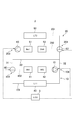
- the cooling water circuit 2 of the first embodiment constitutes a cooling system mounted on an electric vehicle.
- the cooling water circuit 2 includes a first circuit 10, a second circuit 20, and an ECU 3 which is an electronic control unit.
- a circuit in which the cooling water circulates is formed by the first cooling water flow passage 101 and the second cooling water flow passage 102.
- the first coolant channel 101 and the second coolant channel 102 are connected by the first connecting portion 103 and the third connecting portion 104.
- the first connection portion 103 is provided with a first switching valve 60 controlled by the ECU 3.
- a first radiator 40 is provided in the first coolant channel 101.
- the first radiator 40 is a heat exchanger that exchanges heat between the cooling water passing through the first cooling water flow passage 101 and the outside air.
- the second cooling water flow path 102 is provided with an inverter cooling unit 41, a motor generator cooling unit 42, and a first pump 61 controlled by the ECU 3.
- the inverter cooling unit 41 is a part that cools the inverter.
- the inverter converts direct current supplied from the battery into alternating current and supplies it to the motor generator.
- the motor generator cooling unit 42 is a part that cools the motor generator.
- the motor generator is a rotary motor having a function of generating driving force and a function of generating electric power.
- the allowable water temperature of the cooling water circuit for cooling the inverter and the motor generator is generally about 60.degree.
- the first pump 61 is a pump that generates a flow of cooling water flowing to the inverter cooling unit 41 and the motor generator cooling unit 42.
- the first pump 61 is disposed in the direction in which the cooling water flows from the first connection portion 103 through the inverter cooling portion 41 and the motor generator cooling portion 42 to the third connection portion 104.
- a circuit in which the cooling water circulates is formed by the third cooling water flow path 201 and the fourth cooling water flow path 202.
- the third cooling water channel 201 and the fourth cooling water channel 202 are connected by the second connection portion 203 and the fourth connection portion 204.
- the fourth connection portion 204 is provided with a second switching valve 62 controlled by the ECU 3.
- a second radiator 50 is provided in the third coolant channel 201.
- the second radiator 50 is a heat exchanger that exchanges heat between the cooling water passing through the third cooling water passage 201 and the outside air.
- the battery cooling unit 51 is a part that cools the battery.
- the battery is a power supply for driving and supplies power to the inverter.
- the allowable water temperature of the cooling water circuit for cooling the battery is generally about 30 ° C. or so.
- the chiller 52 constitutes a part of the refrigeration circuit, and is a water refrigerant heat exchanger that exchanges heat between the refrigerant flowing in the refrigeration circuit and the cooling water flowing in the second circuit 20.
- the second pump 63 is a pump that generates a flow of cooling water that flows to the battery cooling unit 51 and the chiller 52.
- the second pump 63 is disposed in the direction in which the cooling water flows from the fourth connection portion 204 through the chiller 52 and the battery cooling portion 51 to the second connection portion 203.
- the first circuit 10 and the second circuit 20 are connected by a first connection channel 31 and a second connection channel 32.
- the first connection flow passage 31 is a cooling water flow passage connected to one outflow / inlet side of the first radiator 40 and a cooling water flow passage connected to one outflow / inlet side of the second radiator 50. 2 connecting with the connection unit 203.
- the second connection passage 32 is a third connection portion 104 which is a cooling water passage connected to the other outlet / inlet side of the first radiator 40 and a cooling water passage connected to the other outlet / inlet side of the second radiator 50 4 connection portion 204 is connected.
- the bypass flow passage 30 is provided to connect the first connection flow passage 31 and the second connection flow passage 32.
- the high outside air temperature is, for example, the case where the outside air temperature is higher than the air temperature of 35 ° C. and 30 ° C. which is the allowable water temperature of the battery.
- the first switching valve 60 is controlled to close the first connection channel 31 side and to circulate cooling water in the first circuit 10.
- the second switching valve 62 closes the third coolant channel 201 side, and the coolant is controlled to circulate in the fourth coolant channel 202 and the second connection channel 32 side. Since the first switching valve 60 closes the first connection flow path 31 side, the cooling water flowing from the fourth cooling water flow path 202 into the first connection flow path 31 passes through the bypass flow path 30 to perform the second connection. It flows into the flow path 32 and returns to the fourth cooling water flow path 202.
- the cooling water is circulated in the first circuit 10, and the cooling water cooled by the first radiator 40 can be supplied to the inverter cooling unit 41 and the motor generator cooling unit 42. Therefore, the inverter and motor generator can be cooled.
- the cooling water is circulated from the fourth cooling water passage 202 of the second circuit 20 through the first connection passage 31, the bypass passage 30, and the second connection passage 32, and the battery
- the cooling water cooled by the chiller 52 can be supplied to the cooling unit 51.
- the battery can be cooled.
- the middle / outside air temperature is, for example, a case where the air temperature is about 25 ° C. and the outside air temperature is lower than 30 ° C., which is the allowable water temperature of the battery.
- the first switching valve 60 is controlled to close the first connection channel 31 side and to circulate cooling water in the first circuit 10.
- the second switching valve 62 closes the second connection flow path 32 side, and is controlled so that the cooling water circulates in the second circuit 20. Therefore, the cooling water does not flow in the first connection flow path 31 and the second connection flow path 32, and the cooling water does not flow in the bypass flow path 30.
- a flow shut valve controlled by the ECU 3 is provided on the path of the bypass flow passage 30.
- the cooling water is circulated in the first circuit 10, and the cooling water cooled by the first radiator 40 can be supplied to the inverter cooling unit 41 and the motor generator cooling unit 42. Therefore, the inverter and motor generator can be cooled.
- the cooling water is circulated in the second circuit 20, and the cooling water cooled by the second radiator 50 and the chiller 52 can be supplied to the battery cooling unit 51.
- the battery can be cooled.
- the refrigeration circuit does not operate at the middle and outside air temperatures, and the cooled refrigerant may not be supplied to the chiller 52. In this case, the cooling water is cooled only by the second radiator 50.
- the low outside air temperature is, for example, the case where the air temperature is about 5 ° C. and the battery and the motor generator also need to be warmed up.
- the first switching valve 60 is controlled so as to close the first cooling water flow passage 101 side and to circulate the cooling water to the second cooling water flow passage 102 and the first connection flow passage 31 side. Ru.
- the second switching valve 62 closes the third coolant channel 201 side, and the coolant is controlled to circulate in the second connection channel 32 side.
- the second cooling water flow path 102 of the first circuit 10 passes through the second connection flow path 32, and the fourth cooling water flow path 202 of the second circuit 20 receives the first
- the cooling water flows back to the first circuit 10 through the connection flow path 31 again. Therefore, the heat generated by all the devices can be used to warm up. After the completion of the warm-up, since the cooling water becomes high temperature, the heat can be transferred to the refrigerant in the chiller 52, and the heat can be used for heating the air conditioner.
- the second switching valve 62 When switching from the circulation mode at low outside air temperature shown in FIG. 4 to the circulation mode at middle and outside air temperature shown in FIG. 3, it is preferable to switch the second switching valve 62 after switching the first switching valve 60 .
- the cooling water By switching the first switching valve 60 first, the cooling water can be flowed to the first radiator 40, and the cooling means in the first circuit 10 can be secured.
- the first switching valve 60 is controlled so as to close the second cooling water passage 102 side and allow the cooling water to flow to the first cooling water passage 101 and the first connection passage 31 side.
- the second switching valve 62 is controlled to open all directions of the third coolant channel 201, the fourth coolant channel 202, and the second connection channel 32.
- the cooling water flowing through the fourth cooling water flow channel 202 is divided into the third cooling water flow channel 201 side and the first connection flow channel 31 side.
- the cooling water having flowed into the third cooling water flow path 201 is heat-exchanged in the second radiator 50 to lower its temperature, and is returned to the fourth cooling water flow path 202.
- the cooling water having flowed into the first connection flow path 31 is heat-exchanged in the first radiator 40 to lower its temperature, and is returned to the fourth cooling water flow path 202.
- the cooling water returned to the fourth cooling water flow path 202 is further cooled in the chiller 52 and supplied to the battery cooling unit 51.
- the first switching valve 60 is a first coolant passage on the coolant passage side where the first radiator 40 is disposed.
- the second switching valve 62 closes the second connection flow path 32 side, The first pump 61 and the second pump 63 can be driven.
- the first switching valve 60 it is preferable to switch the first switching valve 60 after switching the second switching valve 62 when the battery is rapidly charged since the outside air temperature is higher than the water temperature to be supplied to the battery cooling unit 51.
- the outside temperature is a low temperature necessary to warm up the battery
- the first switching is performed if the temperature is higher than the low temperature necessary to warm up the battery and lower than the water temperature to be supplied to the battery. It is preferable to switch the second switching valve 62 after switching the valve 60.
- each of the first switching valve 60 and the second switching valve 62 is preferably configured by a three-way valve.
- the number of valves used can be minimized.
- the first switching valve 60 and the second switching valve 62 are not limited to three-way valves as long as they can exhibit the above-described function, and even if they are configured by a combination of two-way valves and four-way valves Good.
- the cooling water circuit 2A which is a modification in which circuit elements are added to the cooling water circuit 2 will be described with reference to FIG.
- the cooling water circuit 2A is obtained by adding a ventilation heat exchanger 43 and a PTC heater 54 to the cooling water circuit 2.
- the ventilation heat exchanger 43 is a heat exchanger for exchanging heat with the cooling water when ventilating the air in the vehicle compartment, and includes a flow path of air discharged from the vehicle compartment and a flow of cooling water. A road is formed. If the outside air temperature is high as in the summer season, the air cooled by the air conditioner is discharged, so the temperature of the cooling water can be lowered. If the outside air temperature is low as in winter, air heated by the air conditioner is discharged, so the temperature of the cooling water can be raised.
- the ventilation heat exchanger 43 is provided in the second cooling water flow path 102 of the first circuit 10A.
- the ventilation heat exchanger 43 is disposed upstream of the inverter cooling unit 41.
- the cooling water cooled or heated by the ventilation heat exchanger 43 is supplied to the inverter cooling unit 41, so that the inverter can be cooled or warmed up.
- the PTC heater 54 is provided in the fourth coolant channel 202 of the second circuit 20A.
- the PTC heater 54 is provided on the upstream side of the battery cooling unit 51.
- the cooling water heated by the PTC heater 54 is supplied to the battery cooling unit 51 and can contribute to the early warm-up of the battery.
- a charger cooling portion 53 is provided which cools the battery charger instead of the PTC heater 54.
- the charger cooling unit 53 is provided in the fourth coolant channel 202 of the second circuit 20B.
- the charger cooling unit 53 is provided on the downstream side of the chiller 52. Therefore, the cooling water cooled by the chiller 52 is supplied to the charger cooling unit 53. Since the temperature of the cooling water determined in the battery cooling unit 51 is lower than the temperature of the cooling water determined in the charger cooling unit 53, the charger cooling unit 53 is disposed downstream of the battery cooling unit 51.
- the cooling water circuits 2, 2A and 2B are controlled by the motor generator cooling unit 42 for cooling the motor generator, the inverter cooling unit 41 for cooling the inverter, and the ECU 3 which is an electronic control unit.
- a cooling unit 51, a chiller 52 that constitutes a part of a refrigeration circuit, a second pump 63 controlled by the ECU 3 to circulate cooling water, and a second radiator 50 are a third cooling water flow passage 201 and a fourth cooling water flow And a second circuit 20, 20A, 20B connected by a path 202.
- a first connection portion 103 provided in a cooling water flow path connected to one outflow inlet / outlet side of the first radiator 40 and cooling connected to one outflow inlet / outlet side of the second radiator 50
- a first connection channel 31 connecting the second connection section 203 provided in the water channel, and a third connection section 104 provided in the cooling water channel connected to the other outlet / inlet side of the first radiator 40
- the second connection flow path 32 connecting the fourth connection portion 204 provided in the cooling water flow path connected to the other outlet / inlet side of the 2 radiator 50, and the third controlled by the ECU 3 to switch the flow of the cooling water
- a first switching valve 60 and a second switching valve 62, and a bypass channel 30 for circulating the cooling water to the battery and the chiller without passing through the second radiator 50 are provided.
- the first circuit 10 and the second circuit 20 are provided.
- the second pump 63 and the second pump 63 it is possible to supply cooling water at a temperature suitable for each allowable water temperature.
- the first connection flow path 31 connects the first connection portion 103 and the second connection portion 203
- the second connection flow path 32 connects the third connection portion 104 and the fourth connection portion 204.
- the bypass flow passage 30 for circulating the cooling water to the battery cooling unit and the chiller without passing through the second radiator 50 is provided, for example, the second outside air temperature is higher than the allowable water temperature of the battery. Passing through the radiator 50 can prevent the temperature of the cooling water from rising, and the cooling water can be cooled only by the chiller.
- the first pump 61 and the second pump 63, and the first switching valve 60 and the second switching valve 62 the first circuit 10 and the second circuit 20 can be achieved with the minimum number of pumps and the number of valves. Can form various cooling water flows.
- the first switching valve 60 is further provided in the first connection portion 103 or the third connection portion 104, and in the second circuit 20, the second connection portion 203 or the fourth connection portion 203 is provided.
- the connection portion 204 is provided with a second switching valve 62.
- the mode of circulating the cooling water can be changed according to the outside air temperature and the state of the battery. As described with reference to FIG. 3, the first switching valve 60 and the second switching valve 62 are switched so as not to allow the cooling water to flow to the first connection channel 31 and the second connection channel 32.
- the circulation of cooling water between the circuit 10 and the second circuit 20 can be made independent.
- warm-up can be performed by switching the first switching valve 60 and the second switching valve 62 so that the cooling water does not flow to the first radiator 40 and the second radiator 50. it can.
- the first switching valve 60 is switched so that the cooling water does not flow to the motor generator cooling unit 42 and the inverter cooling unit 41, and the second switching valve 62 is switched to the second circuit 20 and the first
- the battery can be cooled using the first radiator 40, the second radiator 50, and the chiller 52, so that it is possible to cope with rapid charging.
- the bypass flow passage 30 has one end connected to the first connection flow passage 31, and the second flow passage 30 is a second one as shown in FIGS. 1 to 7.
- the switching valve 62 is provided in the fourth connection portion 204, one end is connected to the second connection flow path 32.
- the second switching valve 62 is provided in the fourth connection portion 204, one end of the bypass flow passage 30 is connected to the second connection flow passage 32, and the other end is connected to the first connection flow passage 31.
- this is an example of the connection mode, and if one end of the bypass flow passage 30 is connected to the second connection flow passage 32, the other end is connected to the fourth cooling water flow passage 202 near the second connection portion 203. It may be done.
- the cooling water can be circulated to the battery cooling unit 51 and the chiller 52 through the bypass flow passage 30. Even if it does, the influence of the temperature rise by the 2nd radiator 50 is excluded, and cooling water can be cooled only with chiller 52.
- the first circuit 10 further includes the first circuit on the side between the first connection portion 103 and the third connection portion 104 on which the motor generator cooling portion 42 and the inverter cooling portion 41 are disposed.
- the pump 61 is provided, and the second pump 20 is disposed between the second connection unit 203 and the fourth connection unit 204 and on the side where the battery cooling unit 51 and the chiller 52 are disposed. Is provided.
- the first pump 61 is disposed in the direction of flowing the cooling water from the first connection portion 103 through the inverter cooling portion 41 and the motor generator cooling portion 42 to the third connection portion 104.
- the second pump 63 is disposed in the direction in which the cooling water flows from the fourth connection portion 204 through the battery cooling portion 51 and the chiller 52 to the second connection portion 203.
- the second pump 63 are disposed in the direction in which the cooling water flows from the second connection portion 203 through the battery cooling portion 51 and the chiller 52 to the fourth connection portion 204.
- the chiller 52 is disposed upstream of the battery cooling unit 51 in the second circuit 20. Since the battery is cooled using the cooling water cooled by the chiller 52, efficient cooling can be achieved by arranging the chiller 52 upstream of the battery cooling unit 51 to be cooled.
- the inverter cooling unit 41 is disposed upstream of the motor generator cooling unit 42. Since the heat tolerance is lower in the inverter, by disposing the inverter cooling unit 41 on the upstream side of the motor generator cooling unit 42, it is possible to supply cooling water with a low temperature to the inverter.
- the PTC heater 54 which is a heater for warm-up, is provided on the upstream side of the battery cooling unit 51.
- the battery cooling unit 51 can not only cool the battery but also apply heat to the battery when the battery warms up, so the PTC heater 54 is provided to supply heated cooling water to warm the battery. be able to.
- a charger cooling unit 53 for cooling the battery charger is provided on the downstream side of the chiller 52.
- the charger cooling unit 53 is preferably disposed downstream of the chiller 52 and further downstream than the battery cooling unit 51. This is because the allowable temperature of the battery is lower than that of the battery charger, and the reverse arrangement may cause an excessive temperature rise of the battery.
- a ventilation heat exchanger 43 which exchanges heat with air discharged from the vehicle compartment is provided on the upstream side of the inverter cooling unit 41. There is.
- the ventilation heat exchanger can perform heat exchange between the cooling water and the air, which is discharged at around 25 ° C. discharged from the room especially in summer, so that the cooling water supplied to the inverter cooling unit 41 can be further cooled.
- the first circuit 10, 10C be provided with a flow shut valve which is controlled by the ECU 3 which is an electronic control unit, and which suppresses the flow of the cooling water.
- the ECU 3 which is an electronic control unit
- the first switching valve 60 and the second switching valve 62 are controlled as shown in FIG. 2 at high external temperature, and the cooling water is circulated to the second radiator 50. I was trying to avoid it. This is the case where the allowable water temperature of the battery is low at about 30 ° C., and when the outside air temperature is high such as 35 ° C. to 40 ° C., the cooling water is the allowable water temperature when the cooling water is turned to the second radiator 50 This is to avoid getting higher than that. On the other hand, since the allowable water temperature of the inverter is generally about 60 ° C., heat exchange between the outside air and the cooling water is effective even at high outside air temperatures.
- the cooling water of the first circuit 10A is circulated to the second radiator 50 when the outside air temperature is high.
- the coolant circuit 2 ⁇ / b> C includes a first circuit 10 ⁇ / b> A and a second circuit 20.
- the first circuit 10A has already been described with reference to FIG.
- the second circuit 20 has already been described with reference to FIG.
- the cooling water circuit 2C is provided with a third connection channel 71 and a fourth connection channel 72.
- the third connection flow path 71 is provided on the first connection portion 103 and the fifth connection portion 105 provided in the first cooling water flow path 101 on the first radiator 40 side, and the fourth connection portion 204 on the second radiator 50 side.
- the sixth connection portion 206 provided in the third cooling water flow path 201.
- the fourth connection flow path 72 is provided on the first cooling water flow path 101 closer to the first radiator 40 than the third connection portion 104, and the second connection side 203 than the second connection portion 203. And the eighth connection portion 205 provided in the third cooling water flow path 201.
- the high outside air temperature is, for example, the case where the outside air temperature is higher than the air temperature of 35 ° C. and 30 ° C. which is the allowable water temperature of the battery.
- the first switching valve 60 is controlled to close the first connection channel 31 side and to circulate the cooling water in the first circuit 10.
- the second switching valve 62 closes the third coolant channel 201 side, and the coolant is controlled to circulate in the fourth coolant channel 202 and the second connection channel 32 side. Since the first switching valve 60 closes the first connection flow path 31 side, the cooling water flowing from the fourth cooling water flow path 202 into the first connection flow path 31 passes through the bypass flow path 30 to perform the second connection. It flows into the flow path 32 and returns to the fourth cooling water flow path 202.
- the cooling water circulates in the first circuit 10.
- the flow is divided into the cooling water circulating in the first circuit and the cooling water flowing to the fourth connection flow path 72.
- the cooling water flowing through the fourth connection flow channel 72 flows from the eighth connection portion 205 into the third cooling water flow channel 201, and is heat-exchanged with the outside air in the second radiator 50.
- the cooling water heat-exchanged in the second radiator 50 flows from the sixth connection portion 206 into the third connection channel 71.
- the cooling water flowing through the third connection flow path 71 is returned to the first circuit from the fifth connection portion 105 and flows to the inverter cooling portion 41 and the motor generator cooling portion 42.
- the cooling water cooled by the first radiator 40 and the second radiator 50 can be supplied. Therefore, the inverter and motor generator can be cooled.
- the cooling water is circulated from the fourth cooling water passage 202 of the second circuit 20 through the first connection passage 31, the bypass passage 30, and the second connection passage 32, and the battery
- the cooling water cooled by the chiller 52 can be supplied to the cooling unit 51.
- the battery can be cooled.
- the middle and outer air temperature is, for example, the case where the air temperature is about 25 ° C. and the outside air temperature is lower than 30 ° C., which is the allowable water temperature of the battery.
- the first switching valve 60 is controlled to close the first connection channel 31 side and to circulate the cooling water in the first circuit 10.
- the second switching valve 62 closes the second connection flow path 32 side, and is controlled so that the cooling water circulates in the second circuit 20. Therefore, the cooling water does not flow in the first connection flow path 31 and the second connection flow path 32, and the cooling water does not flow in the bypass flow path 30.
- the cooling water is circulated in the first circuit 10, and the cooling water cooled by the first radiator 40 can be supplied to the inverter cooling unit 41 and the motor generator cooling unit 42. Therefore, the inverter and motor generator can be cooled.
- the cooling water is circulated in the second circuit 20, and the cooling water cooled by the second radiator 50 and the chiller 52 can be supplied to the battery cooling unit 51.
- the battery can be cooled.
- the refrigeration circuit does not operate at the middle and outside air temperatures, and the cooled refrigerant may not be supplied to the chiller 52. In this case, the cooling water is cooled only by the second radiator 50.
- the low outside air temperature is, for example, the case where the air temperature is about 5 ° C. and the battery and the inverter both require warm-up.
- the first switching valve 60 is controlled so as to close the first cooling water passage 101 side and to circulate the cooling water to the second cooling water passage 102 and the first connection passage 31 side. Ru.
- the second switching valve 62 closes the third coolant channel 201 side, and the coolant is controlled to circulate in the second connection channel 32 side.
- the second cooling water flow path 102 of the first circuit 10 passes through the second connection flow path 32, and the fourth cooling water flow path 202 of the second circuit 20 receives the first
- the cooling water flows back to the first circuit 10 through the connection flow path 31 again. Therefore, the heat generated by all the devices can be used to warm up. After the completion of the warm-up, since the cooling water becomes high temperature, the heat can be transferred to the refrigerant in the chiller 52, and the heat can be used for heating the air conditioner.
- the first switching valve 60 is controlled to close the first connection channel 31 side.
- the second switching valve 62 is controlled to close the second connection channel 32 side.
- the cooling water flowing through the fourth cooling water flow passage 202 is branched to the third cooling water flow passage 201 side and the fourth connecting flow passage 72 side in the eighth connection portion 205.
- the cooling water that has flowed to the fourth connection flow channel 72 flows to the first cooling water flow channel 101, is heat-exchanged in the first radiator 40, and the temperature drops.
- the cooling water cooled in the first radiator 40 flows from the fifth connection portion 105 to the third connection flow path 71, and is returned to the fourth cooling water flow path 202 from the sixth connection portion 206.
- the coolant that has flowed from the eighth connection portion 205 to the third coolant channel 201 is subjected to heat exchange in the second radiator 50 to lower its temperature, and is returned to the fourth coolant channel 202.
- the cooling water returned to the fourth cooling water flow path 202 is further cooled in the chiller 52 and supplied to the battery cooling unit 51.
- At least one of the third connection flow path 71 and the fourth connection flow path 72 is also provided with a flow shut valve which is controlled by the electronic control unit ECU 3 and suppresses the flow of cooling water. preferable. In the case where the cooling water is not desired to flow through the third connection flow channel 71 and the fourth connection flow channel 72, the flow of the cooling water can be reliably suppressed.
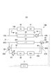
- the cooling water circuit 2D of the third embodiment constitutes a cooling system mounted on an electric vehicle.
- the cooling water circuit 2D includes a first circuit 10D, a second circuit 20D, and an ECU 3 which is an electronic control unit.
- a circuit in which cooling water circulates is formed by the first cooling water flow passage 101 and the second cooling water flow passage 102.
- the first coolant channel 101 and the second coolant channel 102 are connected by the first connecting portion 103 and the third connecting portion 104.
- the first coolant flow path 101 is provided with a first radiator 40 and a first pump 61 controlled by the ECU 3.
- the first radiator 40 is a heat exchanger that exchanges heat between the cooling water passing through the first cooling water flow passage 101 and the outside air.
- the first pump 61 is a pump that generates a flow of cooling water flowing to the first radiator 40.
- the first pump 61 is disposed in the direction in which the cooling water flows from the first connection portion 103 to the third connection portion 104 through the first radiator 40.
- An inverter cooling unit 41 and a motor generator cooling unit 42 are provided in the second cooling water flow path 102.
- the inverter cooling unit 41 is a part that cools the inverter.
- the inverter converts direct current supplied from the battery into alternating current and supplies it to the motor generator.
- the motor generator cooling unit 42 is a part that cools the motor generator.
- the motor generator is a rotary motor having a function of generating driving force and a function of generating electric power.
- the allowable water temperature of the cooling water circuit for cooling the inverter and the motor generator is generally about 60.degree.
- a circuit in which the cooling water circulates is formed by the third cooling water flow path 201 and the fourth cooling water flow path 202.
- the third cooling water channel 201 and the fourth cooling water channel 202 are connected by the second connection portion 203 and the fourth connection portion 204.
- the fourth connection portion 204 is provided with a first switching valve 60 controlled by the ECU 3.
- a second radiator 50 is provided in the third coolant channel 201.
- the second radiator 50 is a heat exchanger that exchanges heat between the cooling water passing through the third cooling water passage 201 and the outside air.
- the battery cooling unit 51 is a part that cools the battery.
- the battery is a power supply for driving and supplies power to the inverter.
- the allowable water temperature of the cooling water circuit for cooling the battery is generally about 30 ° C. or so.
- the chiller 52 constitutes a part of the refrigeration circuit, and is a water refrigerant heat exchanger that exchanges heat between the refrigerant flowing in the refrigeration circuit and the cooling water flowing in the second circuit 20.
- the second pump 63 is a pump that generates a flow of cooling water that flows to the battery cooling unit 51 and the chiller 52.
- the second pump 63 is disposed in the direction in which the cooling water flows from the second connection portion 203 through the chiller 52 and the battery cooling portion 51 to the fourth connection portion 204.
- the fifth connection portion 205 and the sixth connection portion 206 are provided in the fourth coolant channel 202.
- the fifth connection portion 205 is provided with a second switching valve 62 controlled by the ECU 3.
- the first circuit 10D and the second circuit 20D are connected by the first connection channel 31 and the second connection channel 32.
- the first connection flow passage 31 is a cooling water flow passage connected to one outflow / inlet side of the first radiator 40 and a cooling water flow passage connected to one outflow / inlet side of the second radiator 50. 2 connecting with the connection unit 203.
- the second connection passage 32 is a third connection portion 104 which is a cooling water passage connected to the other outlet / inlet side of the first radiator 40 and a cooling water passage connected to the other outlet / inlet side of the second radiator 50 4 connection portion 204 is connected.
- the high outside air temperature is, for example, the case where the outside air temperature is higher than the air temperature of 35 ° C. and 30 ° C. which is the allowable water temperature of the battery.
- the first switching valve 60 closes the side of the fourth cooling water passage 202 in which the battery cooling unit 51 and the chiller 52 are disposed.
- the second switching valve 62 closes the third coolant channel 201 side, and is controlled so that the coolant is circulated to the fourth coolant channel 202 and the bypass channel 30 side. Since the first switching valve 60 closes the fourth coolant channel 202 side, the coolant flowing into the fourth coolant channel 202 is returned to the fourth coolant channel 202 through the bypass channel 30.
- the cooling water having flowed through the first cooling water flow passage 101 is divided into the second cooling water flow passage 102 side and the second connection flow passage 32 side in the third connection portion 104. Since the first switching valve 60 closes the fourth coolant channel 202 side, the coolant flowing into the second connection channel 32 flows through the third coolant channel 201 of the second circuit, and the first connection flow It flows to the passage 31 and returns to the first cooling water passage 101. The coolant that has flowed into the second coolant channel 102 is returned to the first coolant channel 101.
- the cooling water is circulated in the third cooling water flow path 201 of the first circuit 10D and the second circuit 20D, and the inverter cooling unit 41 and the motor generator cooling unit 42 2 Cooling water cooled by the radiator 50 can be supplied. Therefore, the inverter and motor generator can be cooled.
- the cooling water is circulated from the fourth cooling water flow passage 202 of the second circuit 20 through the bypass flow passage 30, and the cooling water cooled by the chiller 52 is supplied to the battery cooling unit 51. be able to. Thus, the battery can be cooled.
- the middle and outer air temperature is, for example, the case where the air temperature is about 25 ° C. and the outside air temperature is lower than 30 ° C., which is the allowable water temperature of the battery.
- the first switching valve 60 closes the second connection flow path 32 side, and is controlled so that the cooling water circulates in the first circuit 10D.
- the second switching valve 62 closes the bypass flow passage 30 side, and the cooling water is controlled to circulate in the second circuit 20D excluding the bypass flow passage 30. Therefore, the cooling water does not flow in the first connection flow path 31 and the second connection flow path 32, and the cooling water does not flow in the bypass flow path 30.
- the cooling water is circulated in the first circuit 10D, and the cooling water cooled by the first radiator 40 can be supplied to the inverter cooling unit 41 and the motor generator cooling unit 42. Therefore, the inverter and motor generator can be cooled.
- the cooling water is circulated in the second circuit 20D, and the cooling water cooled by the second radiator 50 and the chiller 52 can be supplied to the battery cooling unit 51.
- the battery can be cooled.
- the refrigeration circuit does not operate at the middle and outside air temperatures, and the cooled refrigerant may not be supplied to the chiller 52. In this case, the cooling water is cooled only by the second radiator 50.
- the low outside air temperature is, for example, the case where the air temperature is about 5 ° C. and the battery and the motor generator also need to be warmed up.
- the first switching valve 60 is controlled so as to close the third cooling water flow passage 201 side and to circulate the cooling water to the fourth cooling water flow passage 202 and the second connection flow passage 32 side. Ru.
- the first pump 61 is controlled so that the output thereof is reduced or stopped so that the first coolant passage 101 is closed and the coolant is circulated to the second coolant passage 102 side.
- the second switching valve 62 closes the bypass flow passage 30 side, and is controlled so that the cooling water circulates to the fourth cooling water flow passage 202 side.
- a flow shut valve controlled by the ECU 3 is provided on the path of the first cooling water flow path 101.
- the second cooling water flow path 102 of the first circuit 10D passes from the second cooling water flow path 102 to the first connection flow path 31, and the fourth cooling water flow path 202 of the second circuit 20D is The cooling water flows back to the first circuit 10D through it again. Therefore, the heat generated by all the devices can be used to warm up. After the completion of the warm-up, since the cooling water becomes high temperature, the heat can be transferred to the refrigerant in the chiller 52, and the heat can be used for heating the air conditioner.
- the first switching valve 60 When switching from the high outside air temperature shown in FIG. 14 to the inside / outside air temperature shown in FIG. 15, the first switching valve 60 is switched and then the second switching valve 62 is switched, and then the chiller 52 is stopped. Since the first switching valve 60 and the second switching valve 62 are switched to confirm that the second radiator 50 is cooled, the chiller 52 is stopped, so that the battery can be reliably cooled.
- the first switching valve 60 When switching from the inside / outside air temperature shown in FIG. 15 to the high outside air temperature shown in FIG. 14, the first switching valve 60 is switched after the chiller 52 is driven and then the second switching valve 62 is switched. Since the first switching valve 60 and the second switching valve 62 are switched after driving the chiller 52, cooling of the battery by the chiller 52 can be reliably performed.
- the chiller 52 When switching from the inside to outside air temperature shown in FIG. 15 to the low outside air temperature shown in FIG. 16, the chiller 52 is driven after the output of the first pump 61 is reduced or stopped after the first switching valve 60 is switched. Since the output of the first pump 61 is reduced or stopped after switching the first switching valve 60, cooling of the inverter and the motor generator can be ensured.
- the chiller 52 When switching from the low outside air temperature shown in FIG. 16 to the inside / outside air temperature shown in FIG. 15, the chiller 52 is stopped after switching the first switching valve 60 after raising the output of the first pump 61 or starting driving. Do. Since the chiller 52 is stopped after switching, battery cooling can be ensured.
- the first switching valve 60 closes the second connection flow path 32 side, and is controlled so that the cooling water flows in the second circuit 20D.
- the second switching valve 62 is controlled to close the bypass flow passage 30.
- the cooling water circulates through the third cooling water passage 201 and the fourth cooling water passage 202 in the second circuit 20D.
- the coolant that has flowed to the third coolant channel 201 is subjected to heat exchange in the second radiator 50 to lower its temperature, and then flows to the fourth coolant channel 202.
- the cooling water having flowed into the fourth cooling water flow path 202 is further cooled in the chiller 52 and supplied to the battery cooling unit 51.
- the cooling water circuit 2E which is a modification in which circuit elements are added to the cooling water circuit 2D will be described with reference to FIG.
- the cooling water circuit 2E is obtained by adding a charger cooling unit 53 for cooling the battery charger to the cooling water circuit 2D.
- the charger cooling unit 53 is provided in the fourth coolant passage 202 of the second circuit 20E.
- the charger cooling unit 53 is provided on the downstream side of the chiller 52. Therefore, the cooling water cooled by the chiller 52 is supplied to the charger cooling unit 53. Since the temperature of the cooling water determined in the battery cooling unit 51 is lower than the temperature of the cooling water determined in the charger cooling unit 53, the charger cooling unit 53 is disposed downstream of the battery cooling unit 51.
- the cooling water can be supplied to the charger cooling unit 53 as well.
- the PTC heater 54 is provided in the fourth coolant channel 202 of the second circuit 20F.
- the PTC heater 54 is provided on the upstream side of the battery cooling unit 51.
- the cooling water heated by the PTC heater 54 is supplied to the battery cooling unit 51 and can contribute to the early warm-up of the battery.
- the battery can be warmed up by the waste heat of the inverter and motor generator and the heating of the PTC heater 54. .
- the ventilation heat exchanger 43 is a heat exchanger for exchanging heat with the cooling water when ventilating the air in the vehicle compartment, and includes a flow path of air discharged from the vehicle compartment and a flow of cooling water. A road is formed. If the outside air temperature is high as in the summer season, the air cooled by the air conditioner is discharged, so the temperature of the cooling water can be lowered. If the outside air temperature is low as in winter, air heated by the air conditioner is discharged, so the temperature of the cooling water can be raised.
- the ventilation heat exchanger 43 is provided in the second cooling water flow path 102 of the first circuit 10G.
- the ventilation heat exchanger 43 is disposed upstream of the inverter cooling unit 41.
- the cooling water cooled or heated by the ventilation heat exchanger 43 is supplied to the inverter cooling unit 41 and the motor generator cooling unit 42 so that the inverter and the motor generator can be cooled or warmed up.
- the cooling water cooled by the ventilation heat exchanger 43 is supplied to the inverter cooling unit 41 and the motor generator cooling unit 42. can do.
- the cooling water heated by the ventilation heat exchanger 43 is sent to the inverter cooling unit 41 and the motor generator cooling unit 42. Can be supplied.
- the cooling water circuits 2D, 2E, 2F, and 2G include the motor generator cooling unit 42 for cooling the motor generator, the inverter cooling unit 41 for cooling the inverter, and the ECU 3 which is an electronic control unit.
- a first pump 61 for controlling and circulating cooling water, and first circuits 10D and 10G in which a first radiator 40 is connected to each other by a first cooling water channel 101 and a second cooling water channel 102, and a battery are cooled Battery cooling unit 51, a chiller 52 that forms part of a refrigeration circuit, a second pump 63 that is controlled by the ECU 3 and that circulates the cooling water, and a second radiator 50 are the third cooling water flow path 201 and the fourth
- the second circuits 20D, 20E, and 20F connected by the cooling water flow path 202 are provided.
- the first connection portion 103 provided in the cooling water flow path connected to the one outlet / inlet side of the first radiator 40 and the one outlet / inlet side of the second radiator 50
- a first connection flow path 31 connecting the second connection portion 203 provided in the cooling water flow path connected, and a third connection portion 104 provided in the cooling water flow path connected to the other outlet / inlet side of the first radiator 40
- a second connection flow path 32 connecting the fourth connection portion 204 provided in the cooling water flow path connected to the other outflow / inlet side of the second radiator 50, and the battery and chiller without passing through the second radiator 50
- a bypass flow path 30 connecting the fifth connection portion 205 and the sixth connection portion 206 provided in the cooling water flow path of the second circuits 20D, 20E, and 20F so as to circulate water.
- Ri A first switching valve 60 and the second switching valve 62 to be controlled, is provided Ri.
- the first circuit 10D, 10G and the second circuit 20D, 20E, 20F are provided because the allowable water temperature which is the temperature for cooling the battery is different from the allowable water temperature which is the temperature for cooling the motor generator and the inverter.
- the first pump 61 and the second pump 63 respectively, it is possible to supply cooling water at a temperature suitable for the respective allowable water temperature.
- the first connection flow path 31 connects the first connection portion 103 and the second connection portion 203
- the second connection flow path 32 connects the third connection portion 104 and the fourth connection portion 204.
- the bypass flow passage 30 for circulating the cooling water to the battery cooling unit and the chiller without passing through the second radiator 50 is provided, for example, the second outside air temperature is higher than the allowable water temperature of the battery. Passing through the radiator 50 can prevent the temperature of the cooling water from rising, and the cooling water can be cooled only by the chiller.
- the bypass flow passage 30 is provided in the second circuit 20
- the cooling water passing through the second radiator 50 from the first connection flow passage 31 or the second connection flow passage 32 is made to the first circuit side.
- the first pump 61 and the second pump 63, and the first switching valve 60 and the second switching valve 62 the first circuit 10 and the second circuit 20 can be achieved with the minimum number of pumps and the number of valves. Can form various cooling water flows.
- the first switching valve 60 is further provided in the second connection portion 203 or the fourth connection portion 204, and the second switching valve 62 is provided in the fifth connection portion 205 or the sixth connection portion 206.
- the first pump 61 is provided between the first connection portion 103 and the third connection portion 104 on the side where the first radiator 40 is disposed.
- the second pump 63 is disposed between the second connection unit 203 and the fourth connection unit 204 and on the side where the battery cooling unit 51 and the chiller 52 are disposed. Is provided.
- the mode of circulating the cooling water can be changed according to the outside air temperature and the state of the battery.
- the first switching valve 60 closes the fourth cooling water channel side where the battery cooling unit 51 and the chiller 52 are disposed, and the second switching valve 62 is the second radiator 50. Block the side of the third cooling water flow passage where the cooling water is disposed, so that the cooling water does not flow to the second radiator 50 in the second circuit 20D, and the second radiator 50 passes through the first circuit 10D side. It can be compatible with supplying cooling water.
- the cooling water is not allowed to flow in the first connection flow path 31, the second connection flow path 32, and the bypass flow path 30 in the first switching valve 60 and the second switching valve 62.
- the circulation of the cooling water of the first circuit 10D and the second circuit 20D can be made independent.
- warm-up can be performed by switching the first switching valve 60 and the second switching valve 62 so that the cooling water does not flow to the first radiator 40 and the second radiator 50. it can.
- the first switching valve 60 is switched so as not to allow the coolant to flow to the motor generator cooling unit 42 and the inverter cooling unit 41, and the second switching valve 62 is switched to the bypass flow passage 30.
- the second radiator 50 and the chiller 52 can be used to cool the battery by switching so that the battery does not flow, so it is possible to cope with rapid charging.
- each of the first switching valve 60 and the second switching valve 62 is preferably configured by a three-way valve.
- the number of valves used can be minimized.
- the first switching valve 60 and the second switching valve 62 are not limited to three-way valves as long as they can exhibit the above-described function, and even if they are configured by a combination of two-way valves and four-way valves Good.
- the chiller 52 is disposed upstream of the battery cooling unit 51 in the second circuits 20D, 20E, and 20F. Since the battery is cooled using the cooling water cooled by the chiller 52, efficient cooling can be achieved by arranging the chiller 52 upstream of the battery cooling unit 51 to be cooled.
- the inverter cooling unit 41 is disposed upstream of the motor generator cooling unit 42. Since the heat tolerance is lower in the inverter, by disposing the inverter cooling unit 41 on the upstream side of the motor generator cooling unit 42, it is possible to supply cooling water with a low temperature to the inverter.
- the PTC heater 54 which is a heater for warm-up, is provided on the upstream side of the battery cooling unit 51.
- the battery cooling unit 51 can not only cool the battery but also apply heat to the battery when the battery warms up, so the PTC heater 54 is provided to supply heated cooling water to warm the battery. be able to.
- a charger cooling unit 53 for cooling the battery charger is provided on the downstream side of the chiller 52.
- the charger cooling unit 53 is preferably disposed downstream of the chiller 52 and further downstream than the battery cooling unit 51. This is because the allowable temperature of the battery is lower than that of the battery charger, and the reverse arrangement may cause an excessive temperature rise of the battery.
- a ventilation heat exchanger 43 that exchanges heat with air discharged from the vehicle compartment is provided on the upstream side of the inverter cooling unit 41. ing.
- the ventilation heat exchanger can perform heat exchange between the cooling water and the air, which is discharged at around 25 ° C. discharged from the room especially in summer, so that the cooling water supplied to the inverter cooling unit 41 can be further cooled.
- the first cooling water flow path 101 which is the side on which the first radiator 40 is disposed, between the first connection portion 103 and the third connection portion 104. It is also preferable that a flow shut valve which is controlled by the ECU 3 which is an electronic control unit and which suppresses the flow of the cooling water is provided. In the case where the cooling water is not desired to flow to the first radiator 40, the flow of the cooling water can be reliably suppressed.
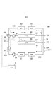
- the cooling water circuit 2H of the fourth embodiment constitutes a cooling system mounted on an electric vehicle.
- the cooling water circuit 2H includes a first circuit 10H, a second circuit 20H, and an ECU 3 which is an electronic control unit.
- a circuit in which cooling water is circulated is formed by the first cooling water flow passage 101, the second cooling water flow passage 102, and the third cooling water flow passage 201.
- the first cooling water flow passage 101 and the second cooling water flow passage 102 are connected by the first connection portion 103 and the second connection portion 104.
- the first connection portion 103 is provided with a first pump 61.
- the first coolant flow path 101 is provided with a first radiator 40 and a first pump 61 controlled by the ECU 3.
- the first radiator 40 is a heat exchanger that exchanges heat between the cooling water passing through the first cooling water flow passage 101 and the outside air.
- the first pump 61 is a pump that generates a flow of cooling water flowing to the first radiator 40 and the second radiator 50.
- the first pump 61 is a direction in which the cooling water flows from the first connection portion 103 to the second connection portion 104 through the first radiator 40, and from the first connection portion 103 to the second radiator 50.
- An inverter cooling unit 41 and a motor generator cooling unit 42 are provided in the second cooling water flow path 102.
- the inverter cooling unit 41 is a part that cools the inverter.
- the inverter converts direct current supplied from the battery into alternating current and supplies it to the motor generator.
- the motor generator cooling unit 42 is a part that cools the motor generator.
- the motor generator is a rotary motor having a function of generating driving force and a function of generating electric power.
- the allowable water temperature of the cooling water circuit for cooling the inverter and the motor generator is generally about 60.degree.
- a second radiator 50 is provided in the third coolant channel 201.
- the second radiator 50 is a heat exchanger that exchanges heat between the cooling water passing through the third cooling water passage 201 and the outside air.
- One end of the third coolant channel 201 is connected to the first coolant channel 101 including the first radiator 40, and the other end is connected to the third connector 106.
- a circuit in which cooling water circulates is formed by the bypass flow passage 30 and the fourth cooling water flow passage 202.
- the bypass flow passage 30 and the fourth cooling water flow passage 202 are connected by the fourth connection portion 203 and the fifth connection portion 204.
- the fourth connection portion 203 is provided with a second switching valve 62 controlled by the ECU 3.
- the bypass flow path 30 is for circulating the cooling water to the battery and the chiller without passing through the first radiator 40 and the second radiator 50.
- the battery cooling unit 51 is a part that cools the battery.
- the battery is a power supply for driving and supplies power to the inverter.
- the allowable water temperature of the cooling water circuit for cooling the battery is generally about 30 ° C. or so.
- the chiller 52 constitutes a part of the refrigeration circuit, and is a water refrigerant heat exchanger that exchanges heat between the refrigerant flowing in the refrigeration circuit and the cooling water flowing in the second circuit 20.
- the second pump 63 is a pump that generates a flow of cooling water that flows to the battery cooling unit 51 and the chiller 52.
- the second pump 63 is disposed in a direction in which the cooling water flows from the fifth connection portion 204 through the chiller 52 and the battery cooling portion 51 to the fourth connection portion 203.
- the first circuit 10H and the second circuit 20H are connected by the first connection channel 31 and the second connection channel 32.
- the first connection flow path 31 connects the first connection portion 103 and the fourth connection portion 203.
- the second connection flow path 32 connects the third connection portion 106 provided on the way of the third cooling water flow path 201 from the second radiator 50 to the second connection portion 104 and the fifth connection portion 204.
- the high outside air temperature is, for example, the case where the outside air temperature is higher than the air temperature of 35 ° C. and 30 ° C. which is the allowable water temperature of the battery.
- the first switching valve 60 opens the first cooling water passage 101 side and the second cooling water passage 102 side.
- the second switching valve 62 closes the first connection flow path 31 side, and is controlled so that the cooling water circulates to the bypass flow path 30 and the fourth cooling water flow path 202 side.
- the cooling water having flowed through the first cooling water flow path 101 flows through the first radiator 40, and is divided into one flowing directly through the first cooling water flow path 101 and one dividing into the third cooling water flow path 201.
- the coolant that has flowed to the third coolant channel 201 is cooled by the second radiator 50.
- the cooling water having flowed through the first cooling water flow passage 101 and the cooling water having flowed through the third cooling water flow passage 201 join at the second connection portion 104 and flow into the second cooling water flow passage 102.
- the cooling water is circulated in the first circuit 10 by driving the first pump 61, and the cooling water cooled by the first radiator 40 and the second radiator 50 is supplied to the inverter cooling unit 41 and the motor generator cooling unit 42. Can. Therefore, the inverter and motor generator can be cooled.
- the cooling water can be circulated in the second circuit 20, and the cooling water cooled by the chiller 52 can be supplied to the battery cooling unit 51.
- the battery can be cooled.
- the middle and outer air temperature is, for example, the case where the air temperature is about 25 ° C. and the outside air temperature is lower than 30 ° C., which is the allowable water temperature of the battery.
- the first switching valve 60 opens the first cooling water channel 101, the second cooling water channel 102, and the first connection channel 31, which are all the channels.
- the second switching valve 62 closes the bypass flow passage 30 side.
- the cooling water circulates through the first circuit 10H and the fourth cooling water passage 202.
- the cooling water cooled by the first radiator 40 and the second radiator 50 can be supplied to the inverter cooling unit 41 and the motor generator cooling unit 42. Therefore, the inverter and motor generator can be cooled.
- the cooling water cooled by the first radiator 40, the second radiator 50, and the chiller 52 can be supplied to the battery cooling unit 51.
- the battery can be cooled.
- the refrigeration circuit does not operate at the middle and outside air temperatures, and the cooled refrigerant may not be supplied to the chiller 52.
- the cooling water is cooled only by the first radiator 40 and the second radiator 50.
- the low outside air temperature is, for example, the case where the air temperature is about 5 ° C. and the battery and the motor generator also need to be warmed up.
- the first switching valve 60 is controlled to close the first cooling water flow passage 101 side and to circulate the cooling water to the second cooling water flow passage 102 and the first connection flow passage 31 side. Ru.
- the second switching valve 62 closes the bypass flow passage 30 side, and is controlled so that the cooling water circulates to the fourth cooling water flow passage 202 side.
- the fourth cooling water flow of the second circuit 20H passes from the second cooling water flow channel 102 of the first circuit 10H to a part of the third cooling water flow channel 201 and the second connection flow channel 32.
- the cooling water flows from the passage 202 through the first connection flow passage 31 back to the first circuit 10 again. Therefore, the heat generated by all the devices can be used to warm up. After the completion of the warm-up, since the cooling water becomes high temperature, the heat can be transferred to the refrigerant in the chiller 52, and the heat can be used for heating the air conditioner.
- the second switching valve 62 When switching from the high outside air temperature shown in FIG. 26 to the inside / outside air temperature shown in FIG. 27, the second switching valve 62 is switched and then the chiller 52 is stopped. Since the chiller 52 is stopped after switching the second switching valve 62 and confirming that the coolant flows to the first radiator 40 and the second radiator 50, the battery can be reliably cooled.
- the second switching valve 62 When switching from the inside / outside air temperature shown in FIG. 27 to the high outside air temperature shown in FIG. 26, the second switching valve 62 is switched after the chiller 52 is driven. Since the second switching valve 62 is switched after driving the chiller 52, cooling of the battery by the chiller 52 can be reliably performed.
- the output of the first pump 61 is reduced or stopped, and then the first switching valve 60 is switched to drive the chiller 52. .
- the first switching valve 60 is switched and then the output of the first pump 61 is increased or the chiller 52 is stopped. Do.
- the first switching valve 60 is controlled to close the second cooling water flow path 102 side.
- the second switching valve 62 is controlled to close the bypass flow passage 30.
- the cooling water flows through the fourth cooling water flow path 202 in the second circuit 20H, and flows from the first connection flow path 31 to the first cooling water flow path 101 and the third cooling water flow path 201. .
- the cooling water which has flowed to the first cooling water flow passage 101 and the third cooling water flow passage 201 is subjected to heat exchange in the first radiator 40 and the second radiator 50 so that the temperature is lowered and flows to the fourth cooling water flow passage 202.
- the cooling water having flowed into the fourth cooling water flow path 202 is further cooled in the chiller 52 and supplied to the battery cooling unit 51.
- cooling water circuit 2J which is a modified example in which circuit elements are added to the cooling water circuit 2H will be described with reference to FIG.
- the cooling water circuit 2J is obtained by adding a charger cooling portion 53 for cooling the battery charger to the cooling water circuit 2H.
- the charger cooling unit 53 is provided in the fourth coolant passage 202 of the second circuit 20J.
- the charger cooling unit 53 is provided on the downstream side of the chiller 52. Therefore, the cooling water cooled by the chiller 52 is supplied to the charger cooling unit 53. Since the temperature of the cooling water determined in the battery cooling unit 51 is lower than the temperature of the cooling water determined in the charger cooling unit 53, the charger cooling unit 53 is disposed downstream of the battery cooling unit 51.
- the cooling water can also be supplied to the charger cooling unit 53.
- the PTC heater 54 is provided in the fourth coolant channel 202 of the second circuit 20K.
- the PTC heater 54 is provided on the upstream side of the battery cooling unit 51.
- the cooling water heated by the PTC heater 54 is supplied to the battery cooling unit 51 and can contribute to the early warm-up of the battery.
- the battery can be warmed up by the waste heat of the inverter and motor generator and the heating of the PTC heater 54. .
- the ventilation heat exchanger 43 is a heat exchanger for exchanging heat with the cooling water when ventilating the air in the vehicle compartment, and includes a flow path of air discharged from the vehicle compartment and a flow of cooling water. A road is formed. If the outside air temperature is high as in the summer season, the air cooled by the air conditioner is discharged, so the temperature of the cooling water can be lowered. If the outside air temperature is low as in winter, air heated by the air conditioner is discharged, so the temperature of the cooling water can be raised.
- the ventilation heat exchanger 43 is provided in the second cooling water flow path 102 of the first circuit 10L.
- the ventilation heat exchanger 43 is disposed upstream of the inverter cooling unit 41.
- the cooling water cooled or heated by the ventilation heat exchanger 43 is supplied to the inverter cooling unit 41 and the motor generator cooling unit 42 so that the inverter and the motor generator can be cooled or warmed up.
- the cooling water cooled by the ventilation heat exchanger 43 is supplied to the inverter cooling unit 41 and the motor generator cooling unit 42. can do.
- the cooling water heated by the ventilation heat exchanger 43 can be supplied to the battery cooling unit 51.
- the third coolant passage 201 provided with the second radiator 50 can be connected to the coolant inlet side of the first radiator 40.
- the throttle 44 can be provided on the downstream side of the first radiator 40 in the first coolant channel 101.
- the throttle 44 can adjust the flow rate of the cooling water flowing into the first radiator 40 and the flow rate of the cooling water flowing into the second radiator 50.
- the throttle 44 may be provided separately from the first radiator 40 as shown in FIG. 37, or the first radiator 40 may be provided with a similar throttle structure. As described above, the throttling structure can be separately or integrally provided on the side where the cooling water flows out from the first radiator 40.
- the third coolant channel 201M provided with the second radiator 50 can be connected to the coolant outlet side of the first radiator 40.
- the first pump 61 may be provided between the first radiator 40 and the second radiator 50.
- the first radiator 40N and the second radiator 50N can be integrally provided.
- the cooling water flowing into the upstream header tank 401 of the first radiator 40 N exchanges heat and then flows to the common header tank 402.
- Part of the cooling water having flowed to the common header tank 402 flows through the first cooling water flow path 101, and the remaining portion flows to the second radiator 50N.
- the cooling water having flowed to the second radiator 50N flows from the downstream header tank 403 to the third cooling water flow path 201.
- the first radiator 40N and the second radiator 50N may be integrally provided, and one cooling water inlet and two cooling water outlets may be formed.
- the cooling water circuits 2H, 2J, 2K, and 2L include the motor generator cooling unit 42 for cooling the motor generator, the inverter cooling unit 41 for cooling the inverter, and the ECU 3 which is an electronic control unit.
- the second circuits 20H, 20J, and 20K in which the unit 51, the chiller 52 that constitutes a part of the refrigeration circuit, and the second pump 63 that is controlled by the ECU 3 and that circulates the cooling water are mutually connected by the cooling water flow path. And have.
- the cooling water flow paths of the first circuits 10H and 10L are the first cooling water flow path 101 in which the first radiator 40 is provided, and the second cooling water flow path 102 in which the motor generator cooling portion 42 and the inverter cooling portion 41 are provided.
- the third coolant channel 201 provided with the second radiator 50, and one end and the other end of each of the first coolant channel 101 and the second coolant channel 102 are connected to the first connection portion 103.
- the third coolant passage 201 is connected at one end to the first coolant passage 101 and at the other end to the second connection portion 104.
- a bypass flow path 30 for circulating the cooling water to the battery and the chiller without passing through the first radiator 40 and the second radiator 50, the battery cooling unit 51 and the chiller 52
- the bypass flow path 30 and the fourth cooling water flow path 202 are connected at the fourth connection portion 203 and the fifth connection portion 204, respectively.
- it is provided on the way of the first connection flow path 31 connecting the first connection portion 103 and the fourth connection portion 203, and the third cooling water flow path 201 extending from the second radiator 50 to the second connection portion 104.
- a second connection flow path 32 connecting the third connection portion 106 and the fifth connection portion 204, and a first switching valve 60 and a second switching valve 62 controlled by the ECU 3 to switch the flow of the cooling water , Is provided.
- the first circuit 10H, 10L and the second circuit 20H, 20J, 20K are provided because the allowable water temperature which is the temperature for cooling the battery is different from the allowable water temperature which is the temperature for cooling the motor generator and the inverter.
- the first pump 61 and the second pump 63 respectively, it is possible to supply cooling water at a temperature suitable for the respective allowable water temperature.
- the first connection flow path 31 connects the first connection portion 103 and the fourth connection portion 203
- the second connection flow path 32 connects the third connection portion 106 and the fifth connection portion 204.
- the cooling water can be prevented from flowing to the first cooling water flow path 101 side at the low outside air temperature, and the first radiator 40 and the second radiator 50
- the battery can be warmed up without turning the cooling water.
- the second circuits 20H, 20J, and 20K are not provided with a radiator that exchanges heat with outside air, for example, the temperature of the cooling water can be passed through the radiator when the outside air temperature is higher than the allowable water temperature of the battery. Can be cooled and the cooling water can be cooled by the chiller 52 alone.
- the first circuits 10H and 10L and the second circuits can be performed with the minimum number of pumps and the number of valves.
- the circuits 20H, 20J, and 20K can be configured to form various cooling water flows.
- a first switching valve 60 is further provided in the first connection portion 103, and a second switching valve 62 is provided in the fourth connection portion 203 or the fifth connection portion 204.
- the first pump 61 is provided in the first cooling water flow path 101 to the first connection portion 103 and the inlet of the first radiator 40, and in the second circuits 20H, 20J, and 20K.
- the second pump 63 is provided in the fourth cooling water flow path 202, the first pump 61 is disposed in the direction of flowing the cooling water to the first radiator 40 side, and the second pump 63 It is disposed in the flow direction from the connection portion 204 to the fourth connection portion 203.
- the third coolant channel 201 to the inlet of the second radiator 50 is thirdly connected.
- the first pump 61 is provided, and in the second circuits 20H, 20J, and 20K, the second pump 63 is provided in the fourth cooling water channel 202, and the first pump 61 is configured to move the cooling water to the second radiator 50 side.
- the second pump 63 is disposed in the flow direction, and is disposed in the direction in which the cooling water flows from the fifth connection portion 204 to the fourth connection portion 203.
- the mode of circulating the cooling water can be changed according to the outside air temperature and the state of the battery.
- the first switching valve 60 opens the first cooling water channel 101 side and the second cooling water channel 102 side
- the second switching valve 62 is the first connection channel 31. Blocking the side to prevent the flow of cooling water to the radiator in the second circuit 20H, and supplying the cooling water passing through the first radiator 40 and the second radiator 50 on the first circuit 10H side. Can be compatible.
- the first switching valve 60 opens all the flow paths, and the second switching valve 62 closes the bypass flow path 30 side, whereby the first radiator 40 and the second radiator are formed.
- the cooling water having passed through 50 can be supplied to both the first circuit 10H and the second circuit 20H.
- the first switching valve 60 closes the first cooling water flow passage 101 side, and the second switching valve 62 closes the bypass flow passage 30 side, so that the first radiator 40 and It is possible to switch so as not to allow the coolant to flow to the second radiator 50, and warm up can be performed.
- the first switching valve 60 is switched so that the cooling water does not flow to the motor generator cooling unit 42 and the inverter cooling unit 41, and the second switching valve 62 is switched to the bypass flow passage 30 Since the battery can be cooled using the first radiator 40, the second radiator 50, and the chiller 52 by switching so as not to flow, it is possible to cope with rapid charging.
- each of the first switching valve 60 and the second switching valve 62 is preferably configured by a three-way valve.
- the number of valves used can be minimized.
- the first switching valve 60 and the second switching valve 62 are not limited to three-way valves as long as they can exhibit the above-described function, and even if they are configured by a combination of two-way valves and four-way valves Good.
- the chiller 52 is disposed upstream of the battery cooling unit 51 in the second circuits 2020 H, 20 J, and 20 K. Since the battery is cooled using the cooling water cooled by the chiller 52, efficient cooling can be achieved by arranging the chiller 52 upstream of the battery cooling unit 51 to be cooled.
- the inverter cooling unit 41 is disposed upstream of the motor generator cooling unit 42. Since the heat tolerance is lower in the inverter, by disposing the inverter cooling unit 41 on the upstream side of the motor generator cooling unit 42, it is possible to supply cooling water with a low temperature to the inverter.
- a PTC heater 54 which is a heater for warm-up, is provided on the upstream side of the battery cooling unit 51.
- the battery cooling unit 51 can not only cool the battery but also apply heat to the battery when the battery warms up, so the PTC heater 54 is provided to supply heated cooling water to warm the battery. be able to.
- a charger cooling unit 53 for cooling the battery charger is provided on the downstream side of the chiller 52.
- the charger cooling unit 53 is preferably disposed downstream of the chiller 52 and further downstream than the battery cooling unit 51. This is because the allowable temperature of the battery is lower than that of the battery charger, and the reverse arrangement may cause an excessive temperature rise of the battery.
- the ventilation heat exchanger 43 that exchanges heat with the air discharged from the vehicle compartment is provided on the upstream side of the inverter cooling unit 41. ing.
- the ventilation heat exchanger can perform heat exchange between the cooling water and the air, which is discharged at around 25 ° C. discharged from the room especially in summer, so that the cooling water supplied to the inverter cooling unit 41 can be further cooled.
- the cooling water circuit of each embodiment can be grasped as follows.
- the cooling water circuits 2, 2A, 2B, 2C, 2D, 2E, 2F, 2G, 2H, 2J, 2K, and 2L cool the first cooling water flow path 101 to which the first radiator 40 is connected and the motor generator.
- the second cooling water flow passage 102 for passing the cooling water through the motor generator cooling unit 42 and the inverter cooling unit 41 for cooling the inverter, the third cooling water flow passage 201 to which the second radiator 50 is connected, and the battery cooling for cooling the battery
- a second pump 63 which is arranged so as to be capable of flow Kutomo coolant to the fourth cooling water passage 202, and a.
- the cooling water circuits 2, 2A, 2B, 2C, 2D, 2E, 2F, 2G, 2H, 2J, 2K, and 2L are the first cooling water flow path 101, the second cooling water flow path 102, and the third cooling water flow.
- the flow path is switched between the path 201, the fourth cooling water flow path 202, and the bypass flow path 30, and the fourth cooling water flow path of the cooling water flowing through the first cooling water flow path 101 and the third cooling water flow path 201
- the first switching valve 60 and the second switching valve 62 are provided so that the inflow to the 202 can be adjusted by cooperating with each other.
- the cooling water circuits 2, 2A, 2B, 2C, 2D, 2E, 2F, 2G, 2H, 2J, 2K, and 2L are the first pump 61, the second pump 63, the first switching valve 60, and the second switching.
- the valve 62 is controlled to cool the first cooling water passage 101, the second cooling water passage 102, the third cooling water passage 201, the fourth cooling water passage 202, and the bypass passage 30 according to the outside air temperature or the battery water temperature.
- the ECU 3 is provided as an electronic control unit capable of executing a plurality of control modes for changing the flow of water.
- the second cooling water channel 102 and the fourth cooling water channel 202 are provided.
- the first pump 61 and the second pump 63 it is possible to supply cooling water having a temperature suitable for the respective allowable water temperature.
- warm-up can be performed without turning the cooling water to the first radiator 40 and the second radiator 50 when the outside air temperature is low.
- bypass flow path 30 for circulating the cooling water to the fourth cooling water flow path 202 without passing through the first cooling water flow path 101 and the third cooling water flow path 201 is provided, for example, Even when the outside air temperature is high and the outside air temperature is high, passing through the first radiator 40 and the second radiator 50 can prevent the temperature of the cooling water from rising, and the cooling water can be cooled by the chiller 52 alone.
- the ECU 3 as the electronic control unit sets the first cooling water passage 101 and the third cooling water passage 201 as the control mode. It is possible to execute the high outside air temperature mode in which the cooling water flowing does not flow at least in the fourth cooling water flow channel 202 and the cooling water flowing in the fourth cooling water flow channel 202 and the bypass flow channel 30 circulates.
- the ECU 3 as the electronic control unit performs cooling in the first cooling water flow passage 101 and the third cooling water flow passage 201 as a control mode when the outside air temperature is a low temperature required to warm up the battery. It is possible to execute the low external temperature mode in which the water does not flow at least in the fourth cooling water flow channel 202, and the cooling water flowing in the second cooling water flow channel 102 and the fourth cooling water flow channel 202 circulates.
- the ECU 3 as the electronic control unit performs the first cooling water passage 101 and the first The cooling water flowing through the third cooling water flow channel 201 executes the inside / outside air temperature mode flowing through the fourth cooling water flow channel 202.
Abstract
The present invention controls a first pump (61), a second pump (63), a first switching valve (60), and a second switching valve (62), and makes it possible to execute multiple control modes for changing, in accordance with the outside air temperature or battery water temperature, the flow of cooling water in a first cooling water pathway (101), a second cooling water pathway (102), a third cooling water pathway (201), a fourth cooling water pathway (202), and a bypass pathway (30).
Description
本出願は、2017年7月24日に出願された日本国特許出願2017-142941号と、2017年7月24日に出願された日本国特許出願2017-142936号と、2017年7月24日に出願された日本国特許出願2017-142938号と、2018年5月7日に出願された日本国特許出願2018-089205号と、に基づくものであって、その優先権の利益を主張するものであり、その特許出願の全ての内容が、参照により本明細書に組み込まれる。
The present application is based on Japanese Patent Application No. 201-142941 filed on July 24, 2017, Japanese Patent Application No. 201-142936 filed on July 24, 2017, and July 24 2017. Patent No. 2017-24938 filed in the United States of America and Japanese Patent Application No. 2018-089205 filed on May 7, 2018, claiming the benefit of its priority And the entire content of that patent application is incorporated herein by reference.
本開示は、冷却水回路に関する。
The present disclosure relates to a coolant circuit.
バッテリを搭載し、モータを主たる動力源又は従たる動力源とする各種電気自動車が知られている。このような電気自動車では、例えば下記特許文献1に記載されているように、モータやインバータを冷却するための冷却回路と、バッテリを冷却するための冷却回路とが設けられている。モータやインバータを冷却するための冷却回路とバッテリを冷却するための冷却回路とでは、求められる冷却水温度が異なる場合があるため各々独立して冷却水が循環される。しかしながら、外気温度条件等によっては、モータやインバータを冷却するための冷却回路とバッテリを冷却するための冷却回路との双方を冷却水が循環するようにした方が好ましい場合もある。更に、モータやインバータを冷却するための冷却回路やバッテリを冷却するための冷却回路の一部にのみ冷却水を流す場合もある。
Various electric vehicles are known which are equipped with a battery and whose motor is a main power source or a secondary power source. In such an electric vehicle, for example, as described in Patent Document 1 below, a cooling circuit for cooling a motor or an inverter and a cooling circuit for cooling a battery are provided. The required cooling water temperature may differ between the cooling circuit for cooling the motor and the inverter and the cooling circuit for cooling the battery, so the cooling water is circulated independently. However, depending on the outside air temperature condition and the like, it may be preferable to circulate the cooling water through both the cooling circuit for cooling the motor and the inverter and the cooling circuit for cooling the battery. Furthermore, the cooling water may flow only to a part of the cooling circuit for cooling the motor and the inverter and the cooling circuit for cooling the battery.
特許文献1では、モータやインバータを冷却するための冷却回路とバッテリを冷却するための冷却回路とにおいて様々な冷却水の循環態様を実現するため、多数のバルブが設けられている。能動部品の点数が増えると信頼性の確保やコストに影響が出るため、冷却水回路全体の機能を損なわない範囲で能動部品であるバルブやポンプの数を抑制したいという要請がある。
In patent document 1, in order to implement | achieve the circulation aspect of various cooling water in the cooling circuit for cooling a motor or an inverter, and the cooling circuit for cooling a battery, many valves are provided. Since the increase in the number of active components affects the reliability and cost, there is a demand to reduce the number of valves and pumps that are active components as long as the function of the entire cooling water circuit is not impaired.
本開示は、バルブやポンプの数量を抑制しつつ所望の循環態様を実現することが可能な冷却水回路を提供することを目的とする。
An object of the present disclosure is to provide a coolant circuit capable of realizing a desired circulation mode while suppressing the number of valves and pumps.
本開示は、冷却水回路であって、第1ラジエータ(40)が接続されている第1冷却水流路(101)と、モータジェネレータを冷却するモータジェネレータ冷却部(42)及びインバータを冷却するインバータ冷却部(41)に冷却水を通す第2冷却水流路(102)と、第2ラジエータ(50)が接続されている第3冷却水流路(201)と、バッテリを冷却するバッテリ冷却部(51)及び冷凍回路の一部を構成するチラー(52)に冷却水を通す第4冷却水流路(202)と、第1冷却水流路及び第3冷却水流路を通さずに第4冷却水流路に冷却水を循環させるためのバイパス流路(30)と、少なくとも第2冷却水流路に冷却水を流すことが可能なように配置されている第1ポンプ(61)と、少なくとも第4冷却水流路に冷却水を流すことが可能なように配置されている第2ポンプ(63)と、第1冷却水流路と、第2冷却水流路と、第3冷却水流路と、第4冷却水流路と、バイパス流路と、の間で流路を切り替えて、第1冷却水流路及び第3冷却水流路を流れる冷却水の第4冷却水流路への流入を互いに協働することで調整することができるように設けられている第1切替バルブ(60)及び第2切替バルブ(62)と、第1ポンプ、第2ポンプ、第1切替バルブ、及び第2切替バルブを制御し、外気温又はバッテリ水温に応じて、第1冷却水流路、第2冷却水流路、第3冷却水流路、第4冷却水流路、及びバイパス流路の冷却水の流れを変更する複数の制御モードを実行可能な電子制御ユニット(3)と、を備える。
The present disclosure relates to a cooling water circuit including a first cooling water flow path (101) to which a first radiator (40) is connected, a motor generator cooling unit (42) for cooling a motor generator, and an inverter for cooling an inverter. A second cooling water flow passage (102) for passing cooling water through the cooling unit (41), a third cooling water flow passage (201) to which the second radiator (50) is connected, and a battery cooling unit (51) for cooling the battery And a fourth cooling water channel (202) for passing cooling water through a chiller (52) which constitutes a part of the refrigeration circuit, and a fourth cooling water channel without passing through the first cooling water channel and the third cooling water channel A bypass flow passage (30) for circulating the cooling water, a first pump (61) arranged to allow the cooling water to flow in at least the second cooling water flow passage, and at least a fourth cooling water flow passage Cooling to The second pump (63) arranged to be able to flow the first coolant water channel, the second coolant water channel, the third coolant water channel, the fourth coolant water channel, and the bypass flow The flow paths are switched between the paths, so that the inflows of the cooling water flowing through the first cooling water flow path and the third cooling water flow path into the fourth cooling water flow path can be adjusted by cooperating with each other Control the first switching valve (60) and the second switching valve (62), the first pump, the second pump, the first switching valve, and the second switching valve, according to the outside air temperature or the battery water temperature An electronic control unit capable of executing a plurality of control modes for changing the flow of cooling water in the first cooling water flow channel, the second cooling water flow channel, the third cooling water flow channel, the fourth cooling water flow channel, and the bypass flow channel And 3).
バッテリを冷却する狙いの温度である許容水温とモータジェネレータ及びインバータを冷却する狙いの温度である許容水温とが異なるので、第2冷却水流路と第4冷却水流路とを設け、それぞれに第1ポンプと第2ポンプとを配置することで、それぞれの許容水温に適した温度の冷却水を供給することができる。第1切替バルブ及び第2切替バルブを切り換えることで、例えば低外気温時に第1ラジエータ及び第2ラジエータに冷却水を回さずに暖機を行うことができる。更に、第1冷却水流路及び第3冷却水流路を通さずに第4冷却水流路に冷却水を循環させるためのバイパス流路を設けているので、例えば、バッテリの許容水温よりも外気温が高い高外気温時に、第1ラジエータ及び第2ラジエータを通すことで冷却水の温度が上昇することを回避し、チラーのみで冷却水を冷却することができる。
Since the allowable water temperature, which is the temperature for cooling the battery, and the allowable water temperature, which is the temperature for cooling the motor generator and the inverter, are different from each other, the second cooling water flow path and the fourth cooling water flow path are provided. By disposing the pump and the second pump, it is possible to supply cooling water at a temperature suitable for the respective allowable water temperature. By switching the first switching valve and the second switching valve, for example, warm-up can be performed without turning the cooling water to the first radiator and the second radiator when the outside air temperature is low. Furthermore, since the bypass flow path for circulating the cooling water in the fourth cooling water flow path without passing through the first cooling water flow path and the third cooling water flow path, the outside air temperature is higher than the allowable water temperature of the battery, for example. It is possible to prevent the temperature of the cooling water from rising by passing through the first radiator and the second radiator when the outside air temperature is high, and the cooling water can be cooled only by the chiller.
本開示は、冷却水回路であって、モータジェネレータを冷却するモータジェネレータ冷却部(42)と、インバータを冷却するインバータ冷却部(41)と、電子制御ユニット(3)により制御され、冷却水を循環させる第1ポンプ(61)と、第1ラジエータ(40)とが互いに冷却水流路(101,102)で繋がれている第1回路(10,10A)と、バッテリを冷却するバッテリ冷却部(51)と、冷凍回路の一部を構成するチラー(52)と、前記電子制御ユニットにより制御され、冷却水を循環させる第2ポンプ(63)と、第2ラジエータ(50)とが冷却水流路(201,202)で繋がれている第2回路(20,20A,20B)と、を備えている。冷却水回路には、第1ラジエータの一方の流出入口側に繋がる冷却水流路に設けられた第1接続部(103)と、第2ラジエータの一方の流出入口側に繋がる冷却水流路に設けられた第2接続部(203)と、を繋ぐ第1接続流路(31)と、第1ラジエータの他方の流出入口側に繋がる冷却水流路に設けられた第3接続部(104)と、第2ラジエータの他方の流出入口側に繋がる冷却水流路に設けられた第4接続部(204)と、を繋ぐ第2接続流路(32)と、第2ラジエータを通さずにバッテリ及びチラーに冷却水を循環させるバイパス流路(30)と、冷却水の流れを切り替えるために、前記電子制御ユニットにより制御される第1切替バルブ(60)及び第2切替バルブ(62)と、が設けられている。
The present disclosure relates to a cooling water circuit, which is controlled by a motor generator cooling unit (42) for cooling a motor generator, an inverter cooling unit (41) for cooling an inverter, and an electronic control unit (3). A first circuit (10, 10A) in which a first pump (61) to be circulated and a first radiator (40) are connected to each other by a cooling water flow passage (101, 102), and a battery cooling portion ( 51), a chiller (52) constituting a part of a refrigeration circuit, a second pump (63) controlled by the electronic control unit to circulate cooling water, and a second radiator (50) And a second circuit (20, 20A, 20B) connected by (201, 202). The cooling water circuit is provided with a first connection portion (103) provided in a cooling water flow passage connected to one outflow inlet / outlet side of the first radiator, and a cooling water flow passage connected to one outflow / inflow inlet side of the second radiator A first connection channel (31) connecting the second connection section (203), and a third connection section (104) provided in a cooling water channel connected to the other outlet / inlet side of the first radiator; 2) A second connection channel (32) connecting the fourth connection (204) provided in the cooling water channel connected to the other outlet / inlet side of the radiator, and the battery and chiller without passing through the second radiator A bypass flow passage (30) for circulating water and a first switching valve (60) and a second switching valve (62) controlled by the electronic control unit to switch the flow of the cooling water are provided. There is.
バッテリを冷却する狙いの温度である許容水温とモータジェネレータ及びインバータを冷却する狙いの温度である許容水温とが異なるので、第1回路と第2回路とを設け、それぞれに第1ポンプと第2ポンプとを配置することで、それぞれの許容水温に適した温度の冷却水を供給することができる。第1接続流路は、第1接続部と第2接続部とを繋いでおり、第2接続流路は、第3接続部と第4接続部とを繋いでいるので、第1切替バルブ及び第2切替バルブを切り換えることで、例えば低外気温時に第1ラジエータ及び第2ラジエータに冷却水を回さずに暖機を行うことができる。更に、第2ラジエータを通さずにバッテリ冷却部及びチラーに冷却水を循環させるバイパス流路を設けているので、例えば、バッテリの許容水温よりも外気温が高い高外気温時に、第2ラジエータを通すことで冷却水の温度が上昇することを回避し、チラーのみで冷却水を冷却することができる。
Since the allowable water temperature which is the temperature for cooling the battery and the allowable water temperature which is the temperature for cooling the motor generator and the inverter are different from each other, the first circuit and the second circuit are provided. By arranging a pump, it is possible to supply cooling water of a temperature suitable for each allowable water temperature. The first connection flow path connects the first connection portion and the second connection portion, and the second connection flow path connects the third connection portion and the fourth connection portion. By switching the second switching valve, for example, warm-up can be performed without turning the cooling water to the first radiator and the second radiator when the outside air temperature is low. Furthermore, since the bypass flow path for circulating the cooling water to the battery cooling unit and the chiller without passing through the second radiator is provided, for example, the second radiator is used at high outside air temperatures where the outside air temperature is higher than the allowable water temperature of the battery. Passing through prevents the temperature of the cooling water from rising, and the cooling water can be cooled by the chiller alone.
本開示は、冷却水回路であって、モータジェネレータを冷却するモータジェネレータ冷却部(42)と、インバータを冷却するインバータ冷却部(41)と、電子制御ユニット(3)により制御され、冷却水を循環させる第1ポンプ(61)と、第1ラジエータ(40)とが互いに冷却水流路(101,102)で繋がれている第1回路(10D,10G)と、バッテリを冷却するバッテリ冷却部(51)と、冷凍回路の一部を構成するチラー(52)と、前記電子制御ユニットにより制御され、冷却水を循環させる第2ポンプ(63)と、第2ラジエータ(50)とが冷却水流路(201,202)で繋がれている第2回路(20D,20E,20F)と、を備えている。冷却水回路には、第1ラジエータの一方の流出入口側に繋がる冷却水流路に設けられた第1接続部(103)と、第2ラジエータの一方の流出入口側に繋がる冷却水流路に設けられた第2接続部(203)と、を繋ぐ第1接続流路(31)と、第1ラジエータの他方の流出入口側に繋がる冷却水流路に設けられた第3接続部(104)と、第2ラジエータの他方の流出入口側に繋がる冷却水流路に設けられた第4接続部(204)と、を繋ぐ第2接続流路(32)と、第2ラジエータを通さずにバッテリ及びチラーに冷却水を循環させるように、第2回路の冷却水流路に設けられた第5接続部(205)と第6接続部(206)とを繋ぐバイパス流路(30)と、冷却水の流れを切り替えるために、前記電子制御ユニットにより制御される第1切替バルブ(60)及び第2切替バルブ(62)と、が設けられている。
The present disclosure relates to a cooling water circuit, which is controlled by a motor generator cooling unit (42) for cooling a motor generator, an inverter cooling unit (41) for cooling an inverter, and an electronic control unit (3). A first circuit (10D, 10G) in which a first pump (61) to be circulated and a first radiator (40) are connected to each other by a cooling water flow passage (101, 102), and a battery cooling portion ( 51), a chiller (52) constituting a part of a refrigeration circuit, a second pump (63) controlled by the electronic control unit to circulate cooling water, and a second radiator (50) And a second circuit (20D, 20E, 20F) connected by (201, 202). The cooling water circuit is provided with a first connection portion (103) provided in a cooling water flow passage connected to one outflow inlet / outlet side of the first radiator, and a cooling water flow passage connected to one outflow / inflow inlet side of the second radiator A first connection channel (31) connecting the second connection section (203), and a third connection section (104) provided in a cooling water channel connected to the other outlet / inlet side of the first radiator; 2) A second connection channel (32) connecting the fourth connection (204) provided in the cooling water channel connected to the other outlet / inlet side of the radiator, and the battery and chiller without passing through the second radiator In order to circulate water, a bypass flow passage (30) connecting the fifth connection portion (205) and the sixth connection portion (206) provided in the cooling water flow passage of the second circuit and the flow of the cooling water are switched Control by the electronic control unit to A switching valve (60) and a second switching valve (62), is provided.
バッテリを冷却する狙いの温度である許容水温とモータジェネレータ及びインバータを冷却する狙いの温度である許容水温とが異なるので、第1回路と第2回路とを設け、それぞれに第1ポンプと第2ポンプとを配置することで、それぞれの許容水温に適した温度の冷却水を供給することができる。第1接続流路は、第1接続部と第2接続部とを繋いでおり、第2接続流路は、第3接続部と第4接続部とを繋いでいるので、第1切替バルブ及び第2切替バルブを切り換えることで、例えば低外気温時に第1ラジエータ及び第2ラジエータに冷却水を回さずに暖機を行うことができる。更に、第2ラジエータを通さずにバッテリ冷却部及びチラーに冷却水を循環させるバイパス流路を設けているので、例えば、バッテリの許容水温よりも外気温が高い高外気温時に、第2ラジエータを通すことで冷却水の温度が上昇することを回避し、チラーのみで冷却水を冷却することができる。
Since the allowable water temperature which is the temperature for cooling the battery and the allowable water temperature which is the temperature for cooling the motor generator and the inverter are different from each other, the first circuit and the second circuit are provided. By arranging a pump, it is possible to supply cooling water of a temperature suitable for each allowable water temperature. The first connection flow path connects the first connection portion and the second connection portion, and the second connection flow path connects the third connection portion and the fourth connection portion. By switching the second switching valve, for example, warm-up can be performed without turning the cooling water to the first radiator and the second radiator when the outside air temperature is low. Furthermore, since the bypass flow path for circulating the cooling water to the battery cooling unit and the chiller without passing through the second radiator is provided, for example, the second radiator is used at high outside air temperatures where the outside air temperature is higher than the allowable water temperature of the battery. Passing through prevents the temperature of the cooling water from rising, and the cooling water can be cooled by the chiller alone.
本開示は、冷却水回路であって、モータジェネレータを冷却するモータジェネレータ冷却部(42)と、インバータを冷却するインバータ冷却部(41)と、電子制御ユニット(3)により制御され、冷却水を循環させる第1ポンプ(61)と、第1ラジエータ(40)と、第2ラジエータ(50)と、が互いに冷却水流路で繋がれている第1回路(10H,10L)と、バッテリを冷却するバッテリ冷却部(51)と、冷凍回路の一部を構成するチラー(52)と、前記電子制御ユニットにより制御され、冷却水を循環させる第2ポンプ(63)と、が互いに冷却水流路で繋がれている第2回路(20H,20J,20K)と、を備えている。第1回路の冷却水流路は、第1ラジエータが設けられている第1冷却水流路(101)と、モータジェネレータ冷却部及びインバータ冷却部が設けられている第2冷却水流路(102)と、第2ラジエータが設けられている第3冷却水流路(201)と、を有し、第1冷却水流路と第2冷却水流路とはそれぞれの一端及び他端が第1接続部(103)及び第2接続部(104)において繋がれており、第3冷却水流路は、一端が第1冷却水流路に繋がれ、他端が第2接続部に繋がれている。第2回路の冷却水流路は、第1ラジエータ及び第2ラジエータを通さずにバッテリ及びチラーに冷却水を循環させるバイパス流路(30)と、バッテリ冷却部及びチラーが設けられている第4冷却水流路(202)と、を有し、バイパス流路と第4冷却水流路とはそれぞれの一端及び他端が第4接続部(203)及び第5接続部(204)において繋がれている。更に、第1接続部と、第4接続部と、を繋ぐ第1接続流路(31)と、第2ラジエータから第2接続部に至る第3冷却水流路の途上に設けられた第3接続部(106)と、第5接続部と、を繋ぐ第2接続流路(32)と、冷却水の流れを切り替えるために、前記電子制御ユニットにより制御される第1切替バルブ(60)及び第2切替バルブ(62)と、が設けられている。
The present disclosure relates to a cooling water circuit, which is controlled by a motor generator cooling unit (42) for cooling a motor generator, an inverter cooling unit (41) for cooling an inverter, and an electronic control unit (3). A battery is cooled by a first circuit (10H, 10L) in which a first pump (61), a first radiator (40), and a second radiator (50) to be circulated are mutually connected by a cooling water flow path A battery cooling unit (51), a chiller (52) constituting a part of a refrigeration circuit, and a second pump (63) controlled by the electronic control unit to circulate cooling water are mutually connected in the cooling water flow path. And a second circuit (20H, 20J, 20K). The cooling water flow passage of the first circuit includes a first cooling water flow passage (101) provided with a first radiator, and a second cooling water flow passage (102) provided with a motor generator cooling unit and an inverter cooling unit. And a third cooling water flow path (201) provided with a second radiator, wherein the first cooling water flow path and the second cooling water flow path have a first connection portion (103) at one end and the other end respectively The third connection channel (104) is connected, and one end of the third coolant channel is connected to the first channel and the other end is connected to the second connector. The cooling water flow path of the second circuit is provided with a bypass flow path (30) for circulating the cooling water to the battery and the chiller without passing through the first radiator and the second radiator, and a fourth cooling provided with the battery cooling unit and the chiller One end and the other end of the bypass flow channel and the fourth cooling water flow channel are connected to each other at the fourth connection portion (203) and the fifth connection portion (204). Furthermore, a third connection provided in the middle of a first connection flow path (31) connecting the first connection portion and the fourth connection portion, and a third cooling water flow path extending from the second radiator to the second connection portion A second connection passage (32) connecting the unit (106) and the fifth connection unit, and a first switching valve (60) and a second control valve controlled by the electronic control unit to switch the flow of cooling water 2 and a switching valve (62) are provided.
バッテリを冷却する狙いの温度である許容水温とモータジェネレータ及びインバータを冷却する狙いの温度である許容水温とが異なるので、第1回路と第2回路とを設け、それぞれに第1ポンプと第2ポンプとを配置することで、それぞれの許容水温に適した温度の冷却水を供給することができる。第1接続流路は、第1接続部と第4接続部とを繋いでおり、第2接続流路は、第3接続部と第5接続部とを繋いでいるので、第1切替バルブ及び第2切替バルブを切り換えることで、例えば、低外気温時に第1冷却水流路側に冷却水を流さないようにすることができ、第1ラジエータ及び第2ラジエータに冷却水を回さずにバッテリの暖機を行うことができる。更に、第2回路には外気と熱交換するラジエータを設けていないので、例えば、バッテリの許容水温よりも外気温が高い高外気温時に、ラジエータを通すことで冷却水の温度が上昇することを回避し、チラーのみで冷却水を冷却することができる。
Since the allowable water temperature which is the temperature for cooling the battery and the allowable water temperature which is the temperature for cooling the motor generator and the inverter are different from each other, the first circuit and the second circuit are provided. By arranging a pump, it is possible to supply cooling water of a temperature suitable for each allowable water temperature. The first connection flow path connects the first connection portion and the fourth connection portion, and the second connection flow path connects the third connection portion and the fifth connection portion. By switching the second switching valve, for example, it is possible to prevent the flow of cooling water to the first cooling water flow channel side at low outside air temperature, and without turning the cooling water to the first radiator and the second radiator, It can warm up. Furthermore, since the second circuit is not provided with a radiator that exchanges heat with the outside air, for example, when the outside air temperature is higher than the allowable water temperature of the battery, the temperature of the cooling water rises by passing through the radiator. It can be avoided and cooling water can be cooled only with a chiller.
尚、「発明の概要」及び「請求の範囲」に記載した括弧内の符号は、後述する「発明を実施するための形態」との対応関係を示すものであって、「発明の概要」及び「請求の範囲」が、後述する「発明を実施するための形態」に限定されることを示すものではない。
The reference numerals in parentheses described in the “Summary of the invention” and the “claims” indicate the correspondence with the “embodiments for carrying out the invention” described later, and the “Summary of the Invention” and The scope of the claims does not indicate that the scope of the present invention is limited to the embodiments described below.
以下、添付図面を参照しながら本実施形態について説明する。説明の理解を容易にするため、各図面において同一の構成要素に対しては可能な限り同一の符号を付して、重複する説明は省略する。
Hereinafter, the present embodiment will be described with reference to the attached drawings. In order to facilitate understanding of the description, the same constituent elements in the drawings are denoted by the same reference numerals as much as possible, and redundant description will be omitted.
第1実施形態の冷却水回路2は、電気自動車に搭載される冷却システムを構成する。図1に示されるように、冷却水回路2は、第1回路10と、第2回路20と、電子制御ユニットであるECU3と、を備えている。第1回路10は、第1冷却水流路101と、第2冷却水流路102とによって、冷却水が循環する回路が形成されている。第1冷却水流路101と第2冷却水流路102とは、第1接続部103と第3接続部104とで繋がれている。第1接続部103には、ECU3で制御される第1切替バルブ60が設けられている。
The cooling water circuit 2 of the first embodiment constitutes a cooling system mounted on an electric vehicle. As shown in FIG. 1, the cooling water circuit 2 includes a first circuit 10, a second circuit 20, and an ECU 3 which is an electronic control unit. In the first circuit 10, a circuit in which the cooling water circulates is formed by the first cooling water flow passage 101 and the second cooling water flow passage 102. The first coolant channel 101 and the second coolant channel 102 are connected by the first connecting portion 103 and the third connecting portion 104. The first connection portion 103 is provided with a first switching valve 60 controlled by the ECU 3.
第1冷却水流路101には、第1ラジエータ40が設けられている。第1ラジエータ40は、第1冷却水流路101を通る冷却水と外気との間で熱交換をする熱交換器である。
A first radiator 40 is provided in the first coolant channel 101. The first radiator 40 is a heat exchanger that exchanges heat between the cooling water passing through the first cooling water flow passage 101 and the outside air.
第2冷却水流路102には、インバータ冷却部41と、モータジェネレータ冷却部42と、ECU3で制御される第1ポンプ61と、が設けられている。インバータ冷却部41は、インバータを冷却する部分である。インバータは、バッテリから供給される直流電流を交流電流に変換してモータジェネレータに供給する。モータジェネレータ冷却部42は、モータジェネレータを冷却する部分である。モータジェネレータは、駆動力を発生する機能と発電する機能とを有する回転電動機である。インバータやモータジェネレータを冷却するための冷却水回路の許容水温は、一般的に60℃程度である。
The second cooling water flow path 102 is provided with an inverter cooling unit 41, a motor generator cooling unit 42, and a first pump 61 controlled by the ECU 3. The inverter cooling unit 41 is a part that cools the inverter. The inverter converts direct current supplied from the battery into alternating current and supplies it to the motor generator. The motor generator cooling unit 42 is a part that cools the motor generator. The motor generator is a rotary motor having a function of generating driving force and a function of generating electric power. The allowable water temperature of the cooling water circuit for cooling the inverter and the motor generator is generally about 60.degree.
第1ポンプ61は、インバータ冷却部41及びモータジェネレータ冷却部42に流れる冷却水の流れを生成するポンプである。本実施形態の場合、第1ポンプ61は、第1接続部103からインバータ冷却部41及びモータジェネレータ冷却部42を通って第3接続部104に冷却水を流す方向に配置されている。
The first pump 61 is a pump that generates a flow of cooling water flowing to the inverter cooling unit 41 and the motor generator cooling unit 42. In the case of the present embodiment, the first pump 61 is disposed in the direction in which the cooling water flows from the first connection portion 103 through the inverter cooling portion 41 and the motor generator cooling portion 42 to the third connection portion 104.
第2回路20は、第3冷却水流路201と、第4冷却水流路202とによって、冷却水が循環する回路が形成されている。第3冷却水流路201と第4冷却水流路202とは、第2接続部203と第4接続部204とで繋がれている。第4接続部204には、ECU3で制御される第2切替バルブ62が設けられている。
In the second circuit 20, a circuit in which the cooling water circulates is formed by the third cooling water flow path 201 and the fourth cooling water flow path 202. The third cooling water channel 201 and the fourth cooling water channel 202 are connected by the second connection portion 203 and the fourth connection portion 204. The fourth connection portion 204 is provided with a second switching valve 62 controlled by the ECU 3.
第3冷却水流路201には、第2ラジエータ50が設けられている。第2ラジエータ50は、第3冷却水流路201を通る冷却水と外気との間で熱交換をする熱交換器である。
A second radiator 50 is provided in the third coolant channel 201. The second radiator 50 is a heat exchanger that exchanges heat between the cooling water passing through the third cooling water passage 201 and the outside air.
第4冷却水流路202には、バッテリ冷却部51と、チラー52と、ECU3で制御される第2ポンプ63と、が設けられている。バッテリ冷却部51は、バッテリを冷却する部分である。バッテリは、駆動用の電源であって、インバータに電力を供給する。バッテリを冷却するための冷却水回路の許容水温は一般的に約30℃程度である。
In the fourth coolant channel 202, a battery cooling unit 51, a chiller 52, and a second pump 63 controlled by the ECU 3 are provided. The battery cooling unit 51 is a part that cools the battery. The battery is a power supply for driving and supplies power to the inverter. The allowable water temperature of the cooling water circuit for cooling the battery is generally about 30 ° C. or so.
チラー52は、冷凍回路の一部を構成するものであって、冷凍回路を流れる冷媒と第2回路20を流れる冷却水とを熱交換する水冷媒熱交換器である。
The chiller 52 constitutes a part of the refrigeration circuit, and is a water refrigerant heat exchanger that exchanges heat between the refrigerant flowing in the refrigeration circuit and the cooling water flowing in the second circuit 20.
第2ポンプ63は、バッテリ冷却部51及びチラー52に流れる冷却水の流れを生成するポンプである。本実施形態の場合、第2ポンプ63は、第4接続部204からチラー52及びバッテリ冷却部51を通って第2接続部203に冷却水を流す方向に配置されている。
The second pump 63 is a pump that generates a flow of cooling water that flows to the battery cooling unit 51 and the chiller 52. In the case of the present embodiment, the second pump 63 is disposed in the direction in which the cooling water flows from the fourth connection portion 204 through the chiller 52 and the battery cooling portion 51 to the second connection portion 203.
第1回路10と第2回路20とは、第1接続流路31及び第2接続流路32によって繋がれている。第1接続流路31は、第1ラジエータ40の一方の流出入口側に繋がる冷却水流路である第1接続部103と、第2ラジエータ50の一方の流出入口側に繋がる冷却水流路である第2接続部203とを繋いでいる。第2接続流路32は、第1ラジエータ40の他方の流出入口側に繋がる冷却水流路である第3接続部104と、第2ラジエータ50の他方の流出入口側に繋がる冷却水流路である第4接続部204と、を繋いでいる。本実施形態の場合、バイパス流路30は、第1接続流路31と第2接続流路32とを繋ぐように設けられている。
The first circuit 10 and the second circuit 20 are connected by a first connection channel 31 and a second connection channel 32. The first connection flow passage 31 is a cooling water flow passage connected to one outflow / inlet side of the first radiator 40 and a cooling water flow passage connected to one outflow / inlet side of the second radiator 50. 2 connecting with the connection unit 203. The second connection passage 32 is a third connection portion 104 which is a cooling water passage connected to the other outlet / inlet side of the first radiator 40 and a cooling water passage connected to the other outlet / inlet side of the second radiator 50 4 connection portion 204 is connected. In the case of the present embodiment, the bypass flow passage 30 is provided to connect the first connection flow passage 31 and the second connection flow passage 32.
続いて、高外気温時の冷却水回路2の動作について、図2を参照しながら説明する。高外気温時とは、例えば気温35℃以上であって、バッテリの許容水温である30℃を外気温が上回っている場合である。
Subsequently, the operation of the cooling water circuit 2 at high outside air temperature will be described with reference to FIG. The high outside air temperature is, for example, the case where the outside air temperature is higher than the air temperature of 35 ° C. and 30 ° C. which is the allowable water temperature of the battery.
図2に示されるように、第1切替バルブ60は、第1接続流路31側を閉塞し、第1回路10内で冷却水が循環するように制御される。第2切替バルブ62は、第3冷却水流路201側を閉塞し、第4冷却水流路202及び第2接続流路32側に冷却水が循環するように制御される。第1切替バルブ60が第1接続流路31側を閉塞しているので、第4冷却水流路202から第1接続流路31に流れ込んだ冷却水は、バイパス流路30を通って第2接続流路32に流れ込み第4冷却水流路202に還流する。
As shown in FIG. 2, the first switching valve 60 is controlled to close the first connection channel 31 side and to circulate cooling water in the first circuit 10. The second switching valve 62 closes the third coolant channel 201 side, and the coolant is controlled to circulate in the fourth coolant channel 202 and the second connection channel 32 side. Since the first switching valve 60 closes the first connection flow path 31 side, the cooling water flowing from the fourth cooling water flow path 202 into the first connection flow path 31 passes through the bypass flow path 30 to perform the second connection. It flows into the flow path 32 and returns to the fourth cooling water flow path 202.
第1ポンプ61を駆動することで第1回路10を冷却水が循環し、インバータ冷却部41及びモータジェネレータ冷却部42に、第1ラジエータ40で冷却した冷却水を供給することができる。従って、インバータ及びモータジェネレータを冷却することができる。
By driving the first pump 61, the cooling water is circulated in the first circuit 10, and the cooling water cooled by the first radiator 40 can be supplied to the inverter cooling unit 41 and the motor generator cooling unit 42. Therefore, the inverter and motor generator can be cooled.
第2ポンプ63を駆動することで、第2回路20の第4冷却水流路202から第1接続流路31、バイパス流路30、第2接続流路32を通って冷却水が循環し、バッテリ冷却部51にチラー52で冷却した冷却水を供給することができる。従って、バッテリを冷却することができる。
By driving the second pump 63, the cooling water is circulated from the fourth cooling water passage 202 of the second circuit 20 through the first connection passage 31, the bypass passage 30, and the second connection passage 32, and the battery The cooling water cooled by the chiller 52 can be supplied to the cooling unit 51. Thus, the battery can be cooled.
続いて、中外気温時の冷却水回路2の動作について、図3を参照しながら説明する。中外気温時とは、例えば気温25℃程度であって、バッテリの許容水温である30℃を外気温が下回っている場合である。
Subsequently, the operation of the cooling water circuit 2 at middle and outer air temperatures will be described with reference to FIG. The middle / outside air temperature is, for example, a case where the air temperature is about 25 ° C. and the outside air temperature is lower than 30 ° C., which is the allowable water temperature of the battery.
図3に示されるように、第1切替バルブ60は、第1接続流路31側を閉塞し、第1回路10内で冷却水が循環するように制御される。第2切替バルブ62は、第2接続流路32側を閉塞し、第2回路20内で冷却水が循環するように制御される。従って、第1接続流路31及び第2接続流路32には冷却水が流れず、バイパス流路30にも冷却水は流れない。また、バイパス流路30側への流入を確実に回避するために、バイパス流路30の経路上にECU3で制御されるフローシャットバルブが設けられていることも好ましい。
As shown in FIG. 3, the first switching valve 60 is controlled to close the first connection channel 31 side and to circulate cooling water in the first circuit 10. The second switching valve 62 closes the second connection flow path 32 side, and is controlled so that the cooling water circulates in the second circuit 20. Therefore, the cooling water does not flow in the first connection flow path 31 and the second connection flow path 32, and the cooling water does not flow in the bypass flow path 30. Moreover, in order to reliably avoid the inflow to the bypass flow passage 30 side, it is also preferable that a flow shut valve controlled by the ECU 3 is provided on the path of the bypass flow passage 30.
第1ポンプ61を駆動することで第1回路10を冷却水が循環し、インバータ冷却部41及びモータジェネレータ冷却部42に、第1ラジエータ40で冷却した冷却水を供給することができる。従って、インバータ及びモータジェネレータを冷却することができる。
By driving the first pump 61, the cooling water is circulated in the first circuit 10, and the cooling water cooled by the first radiator 40 can be supplied to the inverter cooling unit 41 and the motor generator cooling unit 42. Therefore, the inverter and motor generator can be cooled.
第2ポンプ63を駆動することで第2回路20を冷却水が循環し、バッテリ冷却部51に、第2ラジエータ50及びチラー52で冷却した冷却水を供給することできる。従って、バッテリを冷却することができる。尚、中外気温時においては冷凍回路が作動せず、チラー52に冷却された冷媒が供給されない場合もあるが、その場合は第2ラジエータ50のみで冷却水が冷却される。
By driving the second pump 63, the cooling water is circulated in the second circuit 20, and the cooling water cooled by the second radiator 50 and the chiller 52 can be supplied to the battery cooling unit 51. Thus, the battery can be cooled. In some cases, the refrigeration circuit does not operate at the middle and outside air temperatures, and the cooled refrigerant may not be supplied to the chiller 52. In this case, the cooling water is cooled only by the second radiator 50.
続いて、低外気温時の冷却水回路2の動作について、図4を参照しながら説明する。低外気温時とは、例えば気温5℃程度であて、バッテリもモータジェネレータも暖機が必要な場合である。
Subsequently, the operation of the cooling water circuit 2 at the low outside air temperature will be described with reference to FIG. The low outside air temperature is, for example, the case where the air temperature is about 5 ° C. and the battery and the motor generator also need to be warmed up.
図4に示されるように、第1切替バルブ60は、第1冷却水流路101側を閉塞し、第2冷却水流路102及び第1接続流路31側に冷却水が循環するように制御される。第2切替バルブ62は、第3冷却水流路201側を閉塞し、第2接続流路32側に冷却水が循環するように制御される。
As shown in FIG. 4, the first switching valve 60 is controlled so as to close the first cooling water flow passage 101 side and to circulate the cooling water to the second cooling water flow passage 102 and the first connection flow passage 31 side. Ru. The second switching valve 62 closes the third coolant channel 201 side, and the coolant is controlled to circulate in the second connection channel 32 side.
第1ポンプ61及び第2ポンプ63を駆動することで、第1回路10の第2冷却水流路102から第2接続流路32を通り、第2回路20の第4冷却水流路202から第1接続流路31を通って再び第1回路10に冷却水が還流するように流れる。従って、全ての機器の発熱を暖機に用いることができる。暖機完了後は、冷却水が高温になるので、チラー52において冷媒に熱を伝えることができ、エアコン暖房に熱を利用することができる。
By driving the first pump 61 and the second pump 63, the second cooling water flow path 102 of the first circuit 10 passes through the second connection flow path 32, and the fourth cooling water flow path 202 of the second circuit 20 receives the first The cooling water flows back to the first circuit 10 through the connection flow path 31 again. Therefore, the heat generated by all the devices can be used to warm up. After the completion of the warm-up, since the cooling water becomes high temperature, the heat can be transferred to the refrigerant in the chiller 52, and the heat can be used for heating the air conditioner.
尚、図4に示される低外気温時の循環態様から図3に示される中外気温時の循環態様に切り替える場合は、第1切替バルブ60を切り替えた後に第2切替バルブ62を切り替えることが好ましい。第1切替バルブ60を先に切り替えることで、第1ラジエータ40に冷却水を流すことができ、第1回路10における冷却手段を確保することができる。
When switching from the circulation mode at low outside air temperature shown in FIG. 4 to the circulation mode at middle and outside air temperature shown in FIG. 3, it is preferable to switch the second switching valve 62 after switching the first switching valve 60 . By switching the first switching valve 60 first, the cooling water can be flowed to the first radiator 40, and the cooling means in the first circuit 10 can be secured.
続いて、バッテリの急速充電時における冷却水回路2の動作について、図5を参照しながら説明する。バッテリの急速充電時にはバッテリが急激に発熱するため、冷却水回路2の全ての要素を活用してバッテリを冷却する。
Subsequently, the operation of the cooling water circuit 2 at the time of rapid charge of the battery will be described with reference to FIG. Since the battery rapidly generates heat when the battery is rapidly charged, all the elements of the coolant circuit 2 are utilized to cool the battery.
図5に示されるように、第1切替バルブ60は、第2冷却水流路102側を閉塞し、第1冷却水流路101及び第1接続流路31側に冷却水が流れるように制御される。第2切替バルブ62は、第3冷却水流路201、第4冷却水流路202、及び第2接続流路32の全方向を開放するように制御される。
As shown in FIG. 5, the first switching valve 60 is controlled so as to close the second cooling water passage 102 side and allow the cooling water to flow to the first cooling water passage 101 and the first connection passage 31 side. . The second switching valve 62 is controlled to open all directions of the third coolant channel 201, the fourth coolant channel 202, and the second connection channel 32.
第2ポンプ63を駆動することで、第4冷却水流路202を流れる冷却水は、第3冷却水流路201側と第1接続流路31側とに分流する。第3冷却水流路201に流れた冷却水は第2ラジエータ50において熱交換され温度が低下し、第4冷却水流路202に還流する。第1接続流路31に流れた冷却水は第1ラジエータ40において熱交換され温度が低下し、第4冷却水流路202に還流する。第4冷却水流路202に還流した冷却水は、チラー52において更に冷却され、バッテリ冷却部51に供給される。
By driving the second pump 63, the cooling water flowing through the fourth cooling water flow channel 202 is divided into the third cooling water flow channel 201 side and the first connection flow channel 31 side. The cooling water having flowed into the third cooling water flow path 201 is heat-exchanged in the second radiator 50 to lower its temperature, and is returned to the fourth cooling water flow path 202. The cooling water having flowed into the first connection flow path 31 is heat-exchanged in the first radiator 40 to lower its temperature, and is returned to the fourth cooling water flow path 202. The cooling water returned to the fourth cooling water flow path 202 is further cooled in the chiller 52 and supplied to the battery cooling unit 51.
本実施形態では、外気温がモータジェネレータを暖機することが必要な低温である場合に、第1切替バルブ60は、第1ラジエータ40が配置されている冷却水流路側である第1冷却水流路101側を閉塞し、第2切替バルブ62は、第2接続流路32側を閉塞し、
第1ポンプ61及び第2ポンプ63を駆動することができる。 In the present embodiment, when the outside air temperature is a low temperature that requires the motor generator to be warmed up, thefirst switching valve 60 is a first coolant passage on the coolant passage side where the first radiator 40 is disposed. The second switching valve 62 closes the second connection flow path 32 side,
Thefirst pump 61 and the second pump 63 can be driven.
第1ポンプ61及び第2ポンプ63を駆動することができる。 In the present embodiment, when the outside air temperature is a low temperature that requires the motor generator to be warmed up, the
The
外気温が、バッテリ冷却部51に供給すべき水温よりも高温である場合から、バッテリを急速充電する場合に、第2切替バルブ62を切り替えた後に第1切替バルブ60を切り替えることが好ましい。一方、外気温が、バッテリを暖機することが必要な低温である場合から、バッテリを暖機することが必要な低温よりも高く、バッテリに供給すべき水温よりも低い場合に、第1切替バルブ60を切り替えた後に第2切替バルブ62を切り替えることが好ましい。
It is preferable to switch the first switching valve 60 after switching the second switching valve 62 when the battery is rapidly charged since the outside air temperature is higher than the water temperature to be supplied to the battery cooling unit 51. On the other hand, if the outside temperature is a low temperature necessary to warm up the battery, the first switching is performed if the temperature is higher than the low temperature necessary to warm up the battery and lower than the water temperature to be supplied to the battery. It is preferable to switch the second switching valve 62 after switching the valve 60.
本実施形態では、第1切替バルブ60及び第2切替バルブ62は、それぞれ三方弁によって構成されていることが好ましい。第1切替バルブ60及び第2切替バルブ62をそれぞれ三方弁によって構成することで、使用するバルブの数を最小限なものとすることができる。尚、第1切替バルブ60及び第2切替バルブ62は、上記説明した機能を発揮することができれば、三方弁に限定されることはなく、二方弁や四方弁の組み合わせで構成されていてもよい。
In the present embodiment, each of the first switching valve 60 and the second switching valve 62 is preferably configured by a three-way valve. By configuring the first switching valve 60 and the second switching valve 62 with three-way valves, the number of valves used can be minimized. The first switching valve 60 and the second switching valve 62 are not limited to three-way valves as long as they can exhibit the above-described function, and even if they are configured by a combination of two-way valves and four-way valves Good.
続いて、冷却水回路2に、回路要素を追加した変形例である冷却水回路2Aについて、図6を参照しながら説明する。冷却水回路2Aは、冷却水回路2に、換気熱交換器43及びPTCヒータ54を追加したものである。
Subsequently, a cooling water circuit 2A which is a modification in which circuit elements are added to the cooling water circuit 2 will be described with reference to FIG. The cooling water circuit 2A is obtained by adding a ventilation heat exchanger 43 and a PTC heater 54 to the cooling water circuit 2.
換気熱交換器43は、車室内の空気を換気する際に冷却水との間で熱交換をするための熱交換器であって、車室内から排出される空気の流路と冷却水の流路とが形成されている。夏場のように外気温が高ければ空調装置で冷却された空気が排出されるので、冷却水の温度を下げることができる。冬場のように外気温が低ければ空調装置で加温された空気が排出されるので、冷却水の温度を上げることができる。
The ventilation heat exchanger 43 is a heat exchanger for exchanging heat with the cooling water when ventilating the air in the vehicle compartment, and includes a flow path of air discharged from the vehicle compartment and a flow of cooling water. A road is formed. If the outside air temperature is high as in the summer season, the air cooled by the air conditioner is discharged, so the temperature of the cooling water can be lowered. If the outside air temperature is low as in winter, air heated by the air conditioner is discharged, so the temperature of the cooling water can be raised.
換気熱交換器43は、第1回路10Aの第2冷却水流路102に設けられている。換気熱交換器43は、インバータ冷却部41の上流側に配置されている。換気熱交換器43で冷却又は加温された冷却水はインバータ冷却部41に供給され、インバータを冷却又は暖機することができる。
The ventilation heat exchanger 43 is provided in the second cooling water flow path 102 of the first circuit 10A. The ventilation heat exchanger 43 is disposed upstream of the inverter cooling unit 41. The cooling water cooled or heated by the ventilation heat exchanger 43 is supplied to the inverter cooling unit 41, so that the inverter can be cooled or warmed up.
PTCヒータ54は、第2回路20Aの第4冷却水流路202に設けられている。PTCヒータ54は、バッテリ冷却部51よりも上流側に設けられている。PTCヒータ54で加温された冷却水は、バッテリ冷却部51に供給され、バッテリの早期暖機に資することができる。
The PTC heater 54 is provided in the fourth coolant channel 202 of the second circuit 20A. The PTC heater 54 is provided on the upstream side of the battery cooling unit 51. The cooling water heated by the PTC heater 54 is supplied to the battery cooling unit 51 and can contribute to the early warm-up of the battery.
図7に示される冷却水回路2Bでは、PTCヒータ54に変えてバッテリチャージャを冷却するチャージャ冷却部53が設けられている。チャージャ冷却部53は、第2回路20Bの第4冷却水流路202に設けられている。チャージャ冷却部53は、チラー52の下流側に設けられている。従って、チャージャ冷却部53には、チラー52によって冷却された冷却水が供給される。チャージャ冷却部53において求められる冷却水の温度よりも、バッテリ冷却部51において求められる冷却水の温度が低いので、チャージャ冷却部53は、バッテリ冷却部51よりも下流側に配置されている。
In the cooling water circuit 2B shown in FIG. 7, a charger cooling portion 53 is provided which cools the battery charger instead of the PTC heater 54. The charger cooling unit 53 is provided in the fourth coolant channel 202 of the second circuit 20B. The charger cooling unit 53 is provided on the downstream side of the chiller 52. Therefore, the cooling water cooled by the chiller 52 is supplied to the charger cooling unit 53. Since the temperature of the cooling water determined in the battery cooling unit 51 is lower than the temperature of the cooling water determined in the charger cooling unit 53, the charger cooling unit 53 is disposed downstream of the battery cooling unit 51.
上記したように本実施形態に係る冷却水回路2,2A,2Bは、モータジェネレータを冷却するモータジェネレータ冷却部42と、インバータを冷却するインバータ冷却部41と、電子制御ユニットであるECU3により制御され、冷却水を循環させる第1ポンプ61と、第1ラジエータ40とが互いに第1冷却水流路101及び第2冷却水流路102で繋がれている第1回路10,10Aと、バッテリを冷却するバッテリ冷却部51と、冷凍回路の一部を構成するチラー52と、ECU3により制御され、冷却水を循環させる第2ポンプ63と、第2ラジエータ50とが第3冷却水流路201及び第4冷却水流路202で繋がれている第2回路20,20A,20Bと、を備えている。
As described above, the cooling water circuits 2, 2A and 2B according to the present embodiment are controlled by the motor generator cooling unit 42 for cooling the motor generator, the inverter cooling unit 41 for cooling the inverter, and the ECU 3 which is an electronic control unit. A first pump 61 for circulating cooling water, a first circuit 10, 10A in which a first radiator 40 is connected to each other by a first cooling water channel 101 and a second cooling water channel 102, and a battery for cooling a battery A cooling unit 51, a chiller 52 that constitutes a part of a refrigeration circuit, a second pump 63 controlled by the ECU 3 to circulate cooling water, and a second radiator 50 are a third cooling water flow passage 201 and a fourth cooling water flow And a second circuit 20, 20A, 20B connected by a path 202.
冷却水回路2,2A,2Bには、第1ラジエータ40の一方の流出入口側に繋がる冷却水流路に設けられた第1接続部103と、第2ラジエータ50の一方の流出入口側に繋がる冷却水流路に設けられた第2接続部203と、を繋ぐ第1接続流路31と、第1ラジエータ40の他方の流出入口側に繋がる冷却水流路に設けられた第3接続部104と、第2ラジエータ50の他方の流出入口側に繋がる冷却水流路に設けられた第4接続部204と、を繋ぐ第2接続流路32と、冷却水の流れを切り替えるために、ECU3により制御される第1切替バルブ60及び第2切替バルブ62と、第2ラジエータ50を通さずにバッテリ及びチラーに冷却水を循環させるバイパス流路30と、が設けられている。
In the cooling water circuits 2, 2A and 2B, a first connection portion 103 provided in a cooling water flow path connected to one outflow inlet / outlet side of the first radiator 40 and cooling connected to one outflow inlet / outlet side of the second radiator 50 A first connection channel 31 connecting the second connection section 203 provided in the water channel, and a third connection section 104 provided in the cooling water channel connected to the other outlet / inlet side of the first radiator 40; The second connection flow path 32 connecting the fourth connection portion 204 provided in the cooling water flow path connected to the other outlet / inlet side of the 2 radiator 50, and the third controlled by the ECU 3 to switch the flow of the cooling water A first switching valve 60 and a second switching valve 62, and a bypass channel 30 for circulating the cooling water to the battery and the chiller without passing through the second radiator 50 are provided.
バッテリを冷却する狙いの温度である許容水温とモータジェネレータ及びインバータを冷却する狙いの温度である許容水温とが異なるので、第1回路10と第2回路20とを設け、それぞれに第1ポンプ61と第2ポンプ63とを配置することで、それぞれの許容水温に適した温度の冷却水を供給することができる。第1接続流路31は、第1接続部103と第2接続部203とを繋いでおり、第2接続流路32は、第3接続部104と第4接続部204とを繋いでいるので、第1切替バルブ60及び第2切替バルブ62を切り換えることで、例えば低外気温時に第1ラジエータ40及び第2ラジエータ50に冷却水を回さずに暖機を行うことができる。
Since the allowable water temperature which is the temperature for cooling the battery and the allowable water temperature which is the temperature for cooling the motor generator and the inverter are different from each other, the first circuit 10 and the second circuit 20 are provided. By disposing the second pump 63 and the second pump 63, it is possible to supply cooling water at a temperature suitable for each allowable water temperature. The first connection flow path 31 connects the first connection portion 103 and the second connection portion 203, and the second connection flow path 32 connects the third connection portion 104 and the fourth connection portion 204. By switching the first switching valve 60 and the second switching valve 62, for example, warm-up can be performed without turning the cooling water to the first radiator 40 and the second radiator 50 at low external temperature.
更に、第2ラジエータ50を通さずにバッテリ冷却部及びチラーに冷却水を循環させるバイパス流路30を設けているので、例えば、バッテリの許容水温よりも外気温が高い高外気温時に、第2ラジエータ50を通すことで冷却水の温度が上昇することを回避し、チラーのみで冷却水を冷却することができる。このように、第1ポンプ61及び第2ポンプ63と、第1切替バルブ60及び第2切替バルブ62とを用いることで、最小限のポンプ数及びバルブ数で第1回路10及び第2回路20を構成し、様々な冷却水の流れを形成することができる。
Furthermore, since the bypass flow passage 30 for circulating the cooling water to the battery cooling unit and the chiller without passing through the second radiator 50 is provided, for example, the second outside air temperature is higher than the allowable water temperature of the battery. Passing through the radiator 50 can prevent the temperature of the cooling water from rising, and the cooling water can be cooled only by the chiller. Thus, by using the first pump 61 and the second pump 63, and the first switching valve 60 and the second switching valve 62, the first circuit 10 and the second circuit 20 can be achieved with the minimum number of pumps and the number of valves. Can form various cooling water flows.
本実施形態では、更に、第1回路10には、第1接続部103又は第3接続部104に第1切替バルブ60が設けられ、第2回路20には、第2接続部203又は第4接続部204に第2切替バルブ62が設けられている。
In the present embodiment, in the first circuit 10, the first switching valve 60 is further provided in the first connection portion 103 or the third connection portion 104, and in the second circuit 20, the second connection portion 203 or the fourth connection portion 203 is provided. The connection portion 204 is provided with a second switching valve 62.
第1切替バルブ60及び第2切替バルブ62を設けることで、冷却水を循環させる態様を外気温度やバッテリの状態に応じて変化させることができる。図3を参照しながら説明したように、第1切替バルブ60及び第2切替バルブ62を第1接続流路31及び第2接続流路32に冷却水を流さないように切り替えることで、第1回路10と第2回路20との冷却水の循環を独立させることができる。
By providing the first switching valve 60 and the second switching valve 62, the mode of circulating the cooling water can be changed according to the outside air temperature and the state of the battery. As described with reference to FIG. 3, the first switching valve 60 and the second switching valve 62 are switched so as not to allow the cooling water to flow to the first connection channel 31 and the second connection channel 32. The circulation of cooling water between the circuit 10 and the second circuit 20 can be made independent.
図4を参照しながら説明したように、第1切替バルブ60及び第2切替バルブ62を第1ラジエータ40及び第2ラジエータ50に冷却水を流さないように切り替えることで、暖機を行うことができる。図5を参照しながら説明したように、第1切替バルブ60をモータジェネレータ冷却部42及びインバータ冷却部41に冷却水を流さないように切り替え、第2切替バルブ62を第2回路20及び第1回路10の双方に冷却水を流すように切り替えることで、第1ラジエータ40、第2ラジエータ50、及びチラー52を用いてバッテリを冷却することができるので、急速充電に対応することができる。
As described with reference to FIG. 4, warm-up can be performed by switching the first switching valve 60 and the second switching valve 62 so that the cooling water does not flow to the first radiator 40 and the second radiator 50. it can. As described with reference to FIG. 5, the first switching valve 60 is switched so that the cooling water does not flow to the motor generator cooling unit 42 and the inverter cooling unit 41, and the second switching valve 62 is switched to the second circuit 20 and the first By switching the flow of the cooling water to both sides of the circuit 10, the battery can be cooled using the first radiator 40, the second radiator 50, and the chiller 52, so that it is possible to cope with rapid charging.
バイパス流路30は、第2切替バルブ62が第2接続部203に設けられている場合は第1接続流路31に一端が繋がれる一方で、図1から図7に示されるように第2切替バルブ62が第4接続部204に設けられている場合は第2接続流路32に一端が繋がれる。本実施形態では、第2切替バルブ62が第4接続部204に設けられ、バイパス流路30は一端が第2接続流路32に繋がれ他端は第1接続流路31に繋がれている。しかしながら、これは接続態様の一例であって、バイパス流路30の一端が第2接続流路32に繋がれていれば、他端は第2接続部203近傍の第4冷却水流路202に繋がれていてもよい。
When the second switching valve 62 is provided at the second connection portion 203, the bypass flow passage 30 has one end connected to the first connection flow passage 31, and the second flow passage 30 is a second one as shown in FIGS. 1 to 7. When the switching valve 62 is provided in the fourth connection portion 204, one end is connected to the second connection flow path 32. In the present embodiment, the second switching valve 62 is provided in the fourth connection portion 204, one end of the bypass flow passage 30 is connected to the second connection flow passage 32, and the other end is connected to the first connection flow passage 31. . However, this is an example of the connection mode, and if one end of the bypass flow passage 30 is connected to the second connection flow passage 32, the other end is connected to the fourth cooling water flow passage 202 near the second connection portion 203. It may be done.
第2切替バルブ62を第2ラジエータ50に冷却水を流さないように切り替えることで、バイパス流路30を通してバッテリ冷却部51及びチラー52に冷却水を循環させることができるので、高外気温時であっても、第2ラジエータ50による温度上昇の影響を排除し、チラー52のみで冷却水を冷却することができる。
By switching the second switching valve 62 so that the cooling water does not flow to the second radiator 50, the cooling water can be circulated to the battery cooling unit 51 and the chiller 52 through the bypass flow passage 30. Even if it does, the influence of the temperature rise by the 2nd radiator 50 is excluded, and cooling water can be cooled only with chiller 52.
本実施形態では、更に、第1回路10には、第1接続部103と第3接続部104との間であってモータジェネレータ冷却部42及びインバータ冷却部41が配置されている側に第1ポンプ61が設けられており、第2回路20には、第2接続部203と第4接続部204との間であってバッテリ冷却部51及びチラー52が配置されている側に第2ポンプ63が設けられている。
In the present embodiment, the first circuit 10 further includes the first circuit on the side between the first connection portion 103 and the third connection portion 104 on which the motor generator cooling portion 42 and the inverter cooling portion 41 are disposed. The pump 61 is provided, and the second pump 20 is disposed between the second connection unit 203 and the fourth connection unit 204 and on the side where the battery cooling unit 51 and the chiller 52 are disposed. Is provided.
図1から図7に示されるように、第1ポンプ61が、冷却水を第1接続部103からインバータ冷却部41及びモータジェネレータ冷却部42を通って第3接続部104に流す方向に配置されている場合には、第2ポンプ63が、冷却水を第4接続部204からバッテリ冷却部51及び前記チラー52を通って第2接続部203に流す方向に配置される。一方、第1ポンプ61が、冷却水を第3接続部104からインバータ冷却部41及びモータジェネレータ冷却部42を通って第1接続部103に流す方向に配置されている場合には、第2ポンプ63が、冷却水を第2接続部203からバッテリ冷却部51及びチラー52を通って第4接続部204に流す方向に配置される。
As shown in FIGS. 1 to 7, the first pump 61 is disposed in the direction of flowing the cooling water from the first connection portion 103 through the inverter cooling portion 41 and the motor generator cooling portion 42 to the third connection portion 104. In this case, the second pump 63 is disposed in the direction in which the cooling water flows from the fourth connection portion 204 through the battery cooling portion 51 and the chiller 52 to the second connection portion 203. On the other hand, in the case where the first pump 61 is disposed in the direction in which the cooling water flows from the third connection portion 104 through the inverter cooling portion 41 and the motor generator cooling portion 42 to the first connection portion 103, the second pump 63 are disposed in the direction in which the cooling water flows from the second connection portion 203 through the battery cooling portion 51 and the chiller 52 to the fourth connection portion 204.
図4に示されるように、第1切替バルブ60及び第2切替バルブ62を第1ラジエータ40及び第2ラジエータ50に冷却水を流さないように切り替えた場合、モータジェネレータ冷却部42及びインバータ冷却部41が配置されている側の第1回路10と、バッテリ冷却部51及びチラー52が配置されている側の第2回路20と、第1接続流路31と、第2接続流路32とを循環するように冷却水を流すことになる。このように切り替えた場合に、第1ポンプ61及び第2ポンプ63が冷却水を流す方向を同じ循環方向とすることで、冷却水の循環を円滑に行うことができる。
As shown in FIG. 4, when the first switching valve 60 and the second switching valve 62 are switched not to flow the cooling water to the first radiator 40 and the second radiator 50, the motor generator cooling unit 42 and the inverter cooling unit 41, the second circuit 20 on the side where the battery cooling unit 51 and the chiller 52 are disposed, the first connection flow path 31, and the second connection flow path 32. Cooling water will flow to circulate. When switching is performed in this manner, circulation of the cooling water can be smoothly performed by setting the direction in which the first pump 61 and the second pump 63 flow the cooling water to be the same circulation direction.
本実施形態では、第2回路20において、チラー52はバッテリ冷却部51の上流側に配置されている。チラー52で冷却した冷却水を用いてバッテリを冷却するので、冷却対象であるバッテリ冷却部51の上流側にチラー52を配置することで効率的に冷却することができる。
In the present embodiment, the chiller 52 is disposed upstream of the battery cooling unit 51 in the second circuit 20. Since the battery is cooled using the cooling water cooled by the chiller 52, efficient cooling can be achieved by arranging the chiller 52 upstream of the battery cooling unit 51 to be cooled.
本実施形態では、第1回路10において、インバータ冷却部41はモータジェネレータ冷却部42の上流側に配置されている。熱許容度がインバータの方が低いので、インバータ冷却部41をモータジェネレータ冷却部42の上流側に配置することで、温度が低い冷却水をインバータに供給することができる。
In the present embodiment, in the first circuit 10, the inverter cooling unit 41 is disposed upstream of the motor generator cooling unit 42. Since the heat tolerance is lower in the inverter, by disposing the inverter cooling unit 41 on the upstream side of the motor generator cooling unit 42, it is possible to supply cooling water with a low temperature to the inverter.
本実施形態では、図6に示されるように、第2回路20Aにおいて、暖機用のヒータであるPTCヒータ54がバッテリ冷却部51の上流側に設けられている。バッテリ冷却部51は、バッテリを冷却するのみならずバッテリの暖気時にバッテリに熱を付与することもできるので、PTCヒータ54を設けることで、バッテリを暖気するために加温した冷却水を供給することができる。
In the present embodiment, as shown in FIG. 6, in the second circuit 20A, the PTC heater 54, which is a heater for warm-up, is provided on the upstream side of the battery cooling unit 51. The battery cooling unit 51 can not only cool the battery but also apply heat to the battery when the battery warms up, so the PTC heater 54 is provided to supply heated cooling water to warm the battery. be able to.
本実施形態では、図7に示されるように、第2回路20Bにおいて、バッテリチャージャを冷却するチャージャ冷却部53がチラー52の下流側に設けられている。このように配置することで、バッテリチャージャも冷却することができる。チャージャ冷却部53は、チラー52の下流側であってバッテリ冷却部51よりも更に下流側に配置されることが好ましい。バッテリチャージャよりもバッテリの許容水温が低く、逆の配置ではバッテリの過度な温度上昇を招く恐れがあるためである。
In the present embodiment, as shown in FIG. 7, in the second circuit 20B, a charger cooling unit 53 for cooling the battery charger is provided on the downstream side of the chiller 52. By arranging in this way, the battery charger can also be cooled. The charger cooling unit 53 is preferably disposed downstream of the chiller 52 and further downstream than the battery cooling unit 51. This is because the allowable temperature of the battery is lower than that of the battery charger, and the reverse arrangement may cause an excessive temperature rise of the battery.
本実施形態では、図6及び図7に示されるように、第1回路10Aにおいて、車室内から排出される空気と熱交換する換気熱交換器43がインバータ冷却部41の上流側に設けられている。換気熱交換機は、特に夏場に室内から排出される25℃程度の空気と冷却水とを熱交換することができるので、インバータ冷却部41に供給される冷却水を更に冷却することができる。
In the present embodiment, as shown in FIGS. 6 and 7, in the first circuit 10A, a ventilation heat exchanger 43 which exchanges heat with air discharged from the vehicle compartment is provided on the upstream side of the inverter cooling unit 41. There is. The ventilation heat exchanger can perform heat exchange between the cooling water and the air, which is discharged at around 25 ° C. discharged from the room especially in summer, so that the cooling water supplied to the inverter cooling unit 41 can be further cooled.
本実施形態では、第1回路10,10Cには、バイパス流路30に、電子制御ユニットであるECU3により制御され、冷却水の流れを抑制するフローシャットバルブが設けられていることも好ましい。バイパス流路30に冷却水を流したくない態様の場合、確実に冷却水の流れを抑制することができる。
In the present embodiment, it is also preferable that the first circuit 10, 10C be provided with a flow shut valve which is controlled by the ECU 3 which is an electronic control unit, and which suppresses the flow of the cooling water. In the case where the cooling water is not desired to flow through the bypass flow path 30, the flow of the cooling water can be reliably suppressed.
ところで、上記第1実施形態の冷却水回路2では、高外気温時において図2に示されるように第1切替バルブ60及び第2切替バルブ62を制御し、第2ラジエータ50に冷却水を回さないようにしていた。これは、バッテリの許容水温が30℃程度と低い場合であって、外気温が35℃から40℃というような高外気温の場合、第2ラジエータ50に冷却水を回すと冷却水が許容水温よりも高くなってしまうことを回避するためである。一方、インバータの許容水温は一般的に約60℃であるため、高外気温時においても外気と冷却水とを熱交換させることは有効である。
By the way, in the cooling water circuit 2 of the first embodiment, the first switching valve 60 and the second switching valve 62 are controlled as shown in FIG. 2 at high external temperature, and the cooling water is circulated to the second radiator 50. I was trying to avoid it. This is the case where the allowable water temperature of the battery is low at about 30 ° C., and when the outside air temperature is high such as 35 ° C. to 40 ° C., the cooling water is the allowable water temperature when the cooling water is turned to the second radiator 50 This is to avoid getting higher than that. On the other hand, since the allowable water temperature of the inverter is generally about 60 ° C., heat exchange between the outside air and the cooling water is effective even at high outside air temperatures.
そこで、図8に示される第2実施形態の冷却水回路2Cでは、高外気温時に第1回路10Aの冷却水を第2ラジエータ50に循環させるように構成している。図8に示されるように、冷却水回路2Cは、第1回路10Aと、第2回路20とを備えている。第1回路10Aは、図6を参照しながら説明済みであるので、その説明を省略する。第2回路20は、図1を参照しながら説明済みであるので、その説明を省略する。
Therefore, in the cooling water circuit 2C of the second embodiment shown in FIG. 8, the cooling water of the first circuit 10A is circulated to the second radiator 50 when the outside air temperature is high. As shown in FIG. 8, the coolant circuit 2 </ b> C includes a first circuit 10 </ b> A and a second circuit 20. The first circuit 10A has already been described with reference to FIG. The second circuit 20 has already been described with reference to FIG.
冷却水回路2Cには、第3接続流路71と、第4接続流路72と、が設けられている。第3接続流路71は、第1接続部103よりも第1ラジエータ40側の第1冷却水流路101に設けられた第5接続部105と、第4接続部204よりも第2ラジエータ50側の第3冷却水流路201に設けられた第6接続部206と、を繋いでいる。
The cooling water circuit 2C is provided with a third connection channel 71 and a fourth connection channel 72. The third connection flow path 71 is provided on the first connection portion 103 and the fifth connection portion 105 provided in the first cooling water flow path 101 on the first radiator 40 side, and the fourth connection portion 204 on the second radiator 50 side. And the sixth connection portion 206 provided in the third cooling water flow path 201.
第4接続流路72は、第3接続部104よりも第1ラジエータ40側の第1冷却水流路101に設けられた第7接続部106と、第2接続部203よりも第2ラジエータ50側の第3冷却水流路201に設けられた第8接続部205と、を繋いでいる。
The fourth connection flow path 72 is provided on the first cooling water flow path 101 closer to the first radiator 40 than the third connection portion 104, and the second connection side 203 than the second connection portion 203. And the eighth connection portion 205 provided in the third cooling water flow path 201.
続いて、高外気温時の冷却水回路2Cの動作について、図9を参照しながら説明する。高外気温時とは、例えば気温35℃以上であって、バッテリの許容水温である30℃を外気温が上回っている場合である。
Subsequently, the operation of the cooling water circuit 2C at high outside air temperature will be described with reference to FIG. The high outside air temperature is, for example, the case where the outside air temperature is higher than the air temperature of 35 ° C. and 30 ° C. which is the allowable water temperature of the battery.
図9に示されるように、第1切替バルブ60は、第1接続流路31側を閉塞し、第1回路10内で冷却水が循環するように制御される。第2切替バルブ62は、第3冷却水流路201側を閉塞し、第4冷却水流路202及び第2接続流路32側に冷却水が循環するように制御される。第1切替バルブ60が第1接続流路31側を閉塞しているので、第4冷却水流路202から第1接続流路31に流れ込んだ冷却水は、バイパス流路30を通って第2接続流路32に流れ込み第4冷却水流路202に還流する。
As shown in FIG. 9, the first switching valve 60 is controlled to close the first connection channel 31 side and to circulate the cooling water in the first circuit 10. The second switching valve 62 closes the third coolant channel 201 side, and the coolant is controlled to circulate in the fourth coolant channel 202 and the second connection channel 32 side. Since the first switching valve 60 closes the first connection flow path 31 side, the cooling water flowing from the fourth cooling water flow path 202 into the first connection flow path 31 passes through the bypass flow path 30 to perform the second connection. It flows into the flow path 32 and returns to the fourth cooling water flow path 202.
第1ポンプ61を駆動することで第1回路10を冷却水が循環する。第7接続部106において、第4接続流路72がつながれているので、第1回路内を循環する冷却水と第4接続流路72に流れる冷却水とに分流される。
By driving the first pump 61, the cooling water circulates in the first circuit 10. In the seventh connection portion 106, since the fourth connection flow path 72 is connected, the flow is divided into the cooling water circulating in the first circuit and the cooling water flowing to the fourth connection flow path 72.
第4接続流路72を流れる冷却水は、第8接続部205から第3冷却水流路201に流れ込み、第2ラジエータ50において外気と熱交換される。第2ラジエータ50において熱交換された冷却水は、第6接続部206から第3接続流路71に流れ込む。第3接続流路71を流れる冷却水は、第5接続部105から第1回路に還流し、インバータ冷却部41及びモータジェネレータ冷却部42に流れる。このように、第1ラジエータ40及び第2ラジエータ50で冷却した冷却水を供給することができる。従って、インバータ及びモータジェネレータを冷却することができる。
The cooling water flowing through the fourth connection flow channel 72 flows from the eighth connection portion 205 into the third cooling water flow channel 201, and is heat-exchanged with the outside air in the second radiator 50. The cooling water heat-exchanged in the second radiator 50 flows from the sixth connection portion 206 into the third connection channel 71. The cooling water flowing through the third connection flow path 71 is returned to the first circuit from the fifth connection portion 105 and flows to the inverter cooling portion 41 and the motor generator cooling portion 42. Thus, the cooling water cooled by the first radiator 40 and the second radiator 50 can be supplied. Therefore, the inverter and motor generator can be cooled.
第2ポンプ63を駆動することで、第2回路20の第4冷却水流路202から第1接続流路31、バイパス流路30、第2接続流路32を通って冷却水が循環し、バッテリ冷却部51にチラー52で冷却した冷却水を供給することができる。従って、バッテリを冷却することができる。
By driving the second pump 63, the cooling water is circulated from the fourth cooling water passage 202 of the second circuit 20 through the first connection passage 31, the bypass passage 30, and the second connection passage 32, and the battery The cooling water cooled by the chiller 52 can be supplied to the cooling unit 51. Thus, the battery can be cooled.
続いて、中外気温時の冷却水回路2Cの動作について、図10を参照しながら説明する。中外気温時とは、例えば気温25℃程度であって、バッテリの許容水温である30℃を外気温が下回っている場合である。
Subsequently, the operation of the cooling water circuit 2C at the middle and outer air temperatures will be described with reference to FIG. The middle and outer air temperature is, for example, the case where the air temperature is about 25 ° C. and the outside air temperature is lower than 30 ° C., which is the allowable water temperature of the battery.
図10に示されるように、第1切替バルブ60は、第1接続流路31側を閉塞し、第1回路10内で冷却水が循環するように制御される。第2切替バルブ62は、第2接続流路32側を閉塞し、第2回路20内で冷却水が循環するように制御される。従って、第1接続流路31及び第2接続流路32には冷却水が流れず、バイパス流路30にも冷却水は流れない。
As shown in FIG. 10, the first switching valve 60 is controlled to close the first connection channel 31 side and to circulate the cooling water in the first circuit 10. The second switching valve 62 closes the second connection flow path 32 side, and is controlled so that the cooling water circulates in the second circuit 20. Therefore, the cooling water does not flow in the first connection flow path 31 and the second connection flow path 32, and the cooling water does not flow in the bypass flow path 30.
第1ポンプ61を駆動することで第1回路10を冷却水が循環し、インバータ冷却部41及びモータジェネレータ冷却部42に、第1ラジエータ40で冷却した冷却水を供給することができる。従って、インバータ及びモータジェネレータを冷却することができる。
By driving the first pump 61, the cooling water is circulated in the first circuit 10, and the cooling water cooled by the first radiator 40 can be supplied to the inverter cooling unit 41 and the motor generator cooling unit 42. Therefore, the inverter and motor generator can be cooled.
第2ポンプ63を駆動することで第2回路20を冷却水が循環し、バッテリ冷却部51に、第2ラジエータ50及びチラー52で冷却した冷却水を供給することできる。従って、バッテリを冷却することができる。尚、中外気温時においては冷凍回路が作動せず、チラー52に冷却された冷媒が供給されない場合もあるが、その場合は第2ラジエータ50のみで冷却水が冷却される。
By driving the second pump 63, the cooling water is circulated in the second circuit 20, and the cooling water cooled by the second radiator 50 and the chiller 52 can be supplied to the battery cooling unit 51. Thus, the battery can be cooled. In some cases, the refrigeration circuit does not operate at the middle and outside air temperatures, and the cooled refrigerant may not be supplied to the chiller 52. In this case, the cooling water is cooled only by the second radiator 50.
続いて、低外気温時の冷却水回路2Cの動作について、図11を参照しながら説明する。低外気温時とは、例えば気温5℃程度であて、バッテリもインバータも暖機が必要な場合である。
Subsequently, the operation of the cooling water circuit 2C at low outside air temperature will be described with reference to FIG. The low outside air temperature is, for example, the case where the air temperature is about 5 ° C. and the battery and the inverter both require warm-up.
図11に示されるように、第1切替バルブ60は、第1冷却水流路101側を閉塞し、第2冷却水流路102及び第1接続流路31側に冷却水が循環するように制御される。第2切替バルブ62は、第3冷却水流路201側を閉塞し、第2接続流路32側に冷却水が循環するように制御される。
As shown in FIG. 11, the first switching valve 60 is controlled so as to close the first cooling water passage 101 side and to circulate the cooling water to the second cooling water passage 102 and the first connection passage 31 side. Ru. The second switching valve 62 closes the third coolant channel 201 side, and the coolant is controlled to circulate in the second connection channel 32 side.
第1ポンプ61及び第2ポンプ63を駆動することで、第1回路10の第2冷却水流路102から第2接続流路32を通り、第2回路20の第4冷却水流路202から第1接続流路31を通って再び第1回路10に冷却水が還流するように流れる。従って、全ての機器の発熱を暖機に用いることができる。暖機完了後は、冷却水が高温になるので、チラー52において冷媒に熱を伝えることができ、エアコン暖房に熱を利用することができる。
By driving the first pump 61 and the second pump 63, the second cooling water flow path 102 of the first circuit 10 passes through the second connection flow path 32, and the fourth cooling water flow path 202 of the second circuit 20 receives the first The cooling water flows back to the first circuit 10 through the connection flow path 31 again. Therefore, the heat generated by all the devices can be used to warm up. After the completion of the warm-up, since the cooling water becomes high temperature, the heat can be transferred to the refrigerant in the chiller 52, and the heat can be used for heating the air conditioner.
続いて、バッテリの急速充電時における冷却水回路2の動作について、図12を参照しながら説明する。バッテリの急速充電時にはバッテリが急激に発熱するため、冷却水回路2の全ての要素を活用してバッテリを冷却する。
Subsequently, the operation of the cooling water circuit 2 at the time of rapid charge of the battery will be described with reference to FIG. Since the battery rapidly generates heat when the battery is rapidly charged, all the elements of the coolant circuit 2 are utilized to cool the battery.
図12に示されるように、第1切替バルブ60は、第1接続流路31側を閉塞するように制御される。第2切替バルブ62は、第2接続流路32側を閉塞するように制御される。
As shown in FIG. 12, the first switching valve 60 is controlled to close the first connection channel 31 side. The second switching valve 62 is controlled to close the second connection channel 32 side.
第2ポンプ63を駆動することで、第4冷却水流路202を流れる冷却水は、第8接続部205において第3冷却水流路201側と第4接続流路72側とに分流する。第4接続流路72側に流れた冷却水は第1冷却水流路101に流れ、第1ラジエータ40において熱交換され温度が低下する。第1ラジエータ40において冷却された冷却水は、第5接続部105から第3接続流路71に流れ、第6接続部206から第4冷却水流路202に還流する。第8接続部205から第3冷却水流路201に流れた冷却水は第2ラジエータ50において熱交換され温度が低下し、第4冷却水流路202に還流する。第4冷却水流路202に還流した冷却水は、チラー52において更に冷却され、バッテリ冷却部51に供給される。
By driving the second pump 63, the cooling water flowing through the fourth cooling water flow passage 202 is branched to the third cooling water flow passage 201 side and the fourth connecting flow passage 72 side in the eighth connection portion 205. The cooling water that has flowed to the fourth connection flow channel 72 flows to the first cooling water flow channel 101, is heat-exchanged in the first radiator 40, and the temperature drops. The cooling water cooled in the first radiator 40 flows from the fifth connection portion 105 to the third connection flow path 71, and is returned to the fourth cooling water flow path 202 from the sixth connection portion 206. The coolant that has flowed from the eighth connection portion 205 to the third coolant channel 201 is subjected to heat exchange in the second radiator 50 to lower its temperature, and is returned to the fourth coolant channel 202. The cooling water returned to the fourth cooling water flow path 202 is further cooled in the chiller 52 and supplied to the battery cooling unit 51.
本実施形態では、第3接続流路71及び第4接続流路72の少なくとも一方に、電子制御ユニットであるECU3により制御され、冷却水の流れを抑制するフローシャットバルブが設けられていることも好ましい。第3接続流路71及び第4接続流路72に冷却水を流したくない態様の場合、確実に冷却水の流れを抑制することができる。
In the present embodiment, at least one of the third connection flow path 71 and the fourth connection flow path 72 is also provided with a flow shut valve which is controlled by the electronic control unit ECU 3 and suppresses the flow of cooling water. preferable. In the case where the cooling water is not desired to flow through the third connection flow channel 71 and the fourth connection flow channel 72, the flow of the cooling water can be reliably suppressed.
第3実施形態の冷却水回路2Dは、電気自動車に搭載される冷却システムを構成する。図13に示されるように、冷却水回路2Dは、第1回路10Dと、第2回路20Dと、電子制御ユニットであるECU3と、を備えている。第1回路10Dは、第1冷却水流路101と、第2冷却水流路102とによって、冷却水が循環する回路が形成されている。第1冷却水流路101と第2冷却水流路102とは、第1接続部103と第3接続部104とで繋がれている。
The cooling water circuit 2D of the third embodiment constitutes a cooling system mounted on an electric vehicle. As shown in FIG. 13, the cooling water circuit 2D includes a first circuit 10D, a second circuit 20D, and an ECU 3 which is an electronic control unit. In the first circuit 10D, a circuit in which cooling water circulates is formed by the first cooling water flow passage 101 and the second cooling water flow passage 102. The first coolant channel 101 and the second coolant channel 102 are connected by the first connecting portion 103 and the third connecting portion 104.
第1冷却水流路101には、第1ラジエータ40と、ECU3で制御される第1ポンプ61と、が設けられている。第1ラジエータ40は、第1冷却水流路101を通る冷却水と外気との間で熱交換をする熱交換器である。
The first coolant flow path 101 is provided with a first radiator 40 and a first pump 61 controlled by the ECU 3. The first radiator 40 is a heat exchanger that exchanges heat between the cooling water passing through the first cooling water flow passage 101 and the outside air.
第1ポンプ61は、第1ラジエータ40に流れる冷却水の流れを生成するポンプである。本実施形態の場合、第1ポンプ61は、第1接続部103から第1ラジエータ40を通って第3接続部104に冷却水を流す方向に配置されている。
The first pump 61 is a pump that generates a flow of cooling water flowing to the first radiator 40. In the case of the present embodiment, the first pump 61 is disposed in the direction in which the cooling water flows from the first connection portion 103 to the third connection portion 104 through the first radiator 40.
第2冷却水流路102には、インバータ冷却部41と、モータジェネレータ冷却部42と、が設けられている。インバータ冷却部41は、インバータを冷却する部分である。インバータは、バッテリから供給される直流電流を交流電流に変換してモータジェネレータに供給する。モータジェネレータ冷却部42は、モータジェネレータを冷却する部分である。モータジェネレータは、駆動力を発生する機能と発電する機能とを有する回転電動機である。インバータやモータジェネレータを冷却するための冷却水回路の許容水温は、一般的に60℃程度である。
An inverter cooling unit 41 and a motor generator cooling unit 42 are provided in the second cooling water flow path 102. The inverter cooling unit 41 is a part that cools the inverter. The inverter converts direct current supplied from the battery into alternating current and supplies it to the motor generator. The motor generator cooling unit 42 is a part that cools the motor generator. The motor generator is a rotary motor having a function of generating driving force and a function of generating electric power. The allowable water temperature of the cooling water circuit for cooling the inverter and the motor generator is generally about 60.degree.
第2回路20Dは、第3冷却水流路201と、第4冷却水流路202とによって、冷却水が循環する回路が形成されている。第3冷却水流路201と第4冷却水流路202とは、第2接続部203と第4接続部204とで繋がれている。第4接続部204には、ECU3で制御される第1切替バルブ60が設けられている。
In the second circuit 20D, a circuit in which the cooling water circulates is formed by the third cooling water flow path 201 and the fourth cooling water flow path 202. The third cooling water channel 201 and the fourth cooling water channel 202 are connected by the second connection portion 203 and the fourth connection portion 204. The fourth connection portion 204 is provided with a first switching valve 60 controlled by the ECU 3.
第3冷却水流路201には、第2ラジエータ50が設けられている。第2ラジエータ50は、第3冷却水流路201を通る冷却水と外気との間で熱交換をする熱交換器である。
A second radiator 50 is provided in the third coolant channel 201. The second radiator 50 is a heat exchanger that exchanges heat between the cooling water passing through the third cooling water passage 201 and the outside air.
第4冷却水流路202には、バッテリ冷却部51と、チラー52と、ECU3で制御される第2ポンプ63と、が設けられている。バッテリ冷却部51は、バッテリを冷却する部分である。バッテリは、駆動用の電源であって、インバータに電力を供給する。バッテリを冷却するための冷却水回路の許容水温は一般的に約30℃程度である。
In the fourth coolant channel 202, a battery cooling unit 51, a chiller 52, and a second pump 63 controlled by the ECU 3 are provided. The battery cooling unit 51 is a part that cools the battery. The battery is a power supply for driving and supplies power to the inverter. The allowable water temperature of the cooling water circuit for cooling the battery is generally about 30 ° C. or so.
チラー52は、冷凍回路の一部を構成するものであって、冷凍回路を流れる冷媒と第2回路20を流れる冷却水とを熱交換する水冷媒熱交換器である。
The chiller 52 constitutes a part of the refrigeration circuit, and is a water refrigerant heat exchanger that exchanges heat between the refrigerant flowing in the refrigeration circuit and the cooling water flowing in the second circuit 20.
第2ポンプ63は、バッテリ冷却部51及びチラー52に流れる冷却水の流れを生成するポンプである。本実施形態の場合、第2ポンプ63は、第2接続部203からチラー52及びバッテリ冷却部51を通って第4接続部204に冷却水を流す方向に配置されている。
The second pump 63 is a pump that generates a flow of cooling water that flows to the battery cooling unit 51 and the chiller 52. In the case of the present embodiment, the second pump 63 is disposed in the direction in which the cooling water flows from the second connection portion 203 through the chiller 52 and the battery cooling portion 51 to the fourth connection portion 204.
第2ラジエータ50を通さずにバッテリ及びチラーに冷却水を循環させるように、第2回路20の冷却水流路に設けられた第5接続部205と第6接続部206とを繋ぐバイパス流路30が設けられている。第5接続部205及び第6接続部206は、第4冷却水流路202に設けられている。第5接続部205には、ECU3で制御される第2切替バルブ62が設けられている。
A bypass flow passage 30 connecting the fifth connection portion 205 and the sixth connection portion 206 provided in the cooling water flow passage of the second circuit 20 so as to circulate the cooling water to the battery and the chiller without passing through the second radiator 50. Is provided. The fifth connection portion 205 and the sixth connection portion 206 are provided in the fourth coolant channel 202. The fifth connection portion 205 is provided with a second switching valve 62 controlled by the ECU 3.
第1回路10Dと第2回路20Dとは、第1接続流路31及び第2接続流路32によって繋がれている。第1接続流路31は、第1ラジエータ40の一方の流出入口側に繋がる冷却水流路である第1接続部103と、第2ラジエータ50の一方の流出入口側に繋がる冷却水流路である第2接続部203とを繋いでいる。第2接続流路32は、第1ラジエータ40の他方の流出入口側に繋がる冷却水流路である第3接続部104と、第2ラジエータ50の他方の流出入口側に繋がる冷却水流路である第4接続部204と、を繋いでいる。
The first circuit 10D and the second circuit 20D are connected by the first connection channel 31 and the second connection channel 32. The first connection flow passage 31 is a cooling water flow passage connected to one outflow / inlet side of the first radiator 40 and a cooling water flow passage connected to one outflow / inlet side of the second radiator 50. 2 connecting with the connection unit 203. The second connection passage 32 is a third connection portion 104 which is a cooling water passage connected to the other outlet / inlet side of the first radiator 40 and a cooling water passage connected to the other outlet / inlet side of the second radiator 50 4 connection portion 204 is connected.
続いて、高外気温時の冷却水回路2Dの動作について、図14を参照しながら説明する。高外気温時とは、例えば気温35℃以上であって、バッテリの許容水温である30℃を外気温が上回っている場合である。
Subsequently, the operation of the cooling water circuit 2D at high outside air temperature will be described with reference to FIG. The high outside air temperature is, for example, the case where the outside air temperature is higher than the air temperature of 35 ° C. and 30 ° C. which is the allowable water temperature of the battery.
図14に示されるように、第1切替バルブ60は、バッテリ冷却部51及びチラー52が配置されている第4冷却水流路202側を閉塞する。第2切替バルブ62は、第3冷却水流路201側を閉塞し、第4冷却水流路202及びバイパス流路30側に冷却水が循環するように制御される。第1切替バルブ60が第4冷却水流路202側を閉塞しているので、第4冷却水流路202に流れ込んだ冷却水は、バイパス流路30を通って第4冷却水流路202に還流する。
As shown in FIG. 14, the first switching valve 60 closes the side of the fourth cooling water passage 202 in which the battery cooling unit 51 and the chiller 52 are disposed. The second switching valve 62 closes the third coolant channel 201 side, and is controlled so that the coolant is circulated to the fourth coolant channel 202 and the bypass channel 30 side. Since the first switching valve 60 closes the fourth coolant channel 202 side, the coolant flowing into the fourth coolant channel 202 is returned to the fourth coolant channel 202 through the bypass channel 30.
一方、第1冷却水流路101を流れた冷却水は、第3接続部104において、第2冷却水流路102側と第2接続流路32側とに分流する。第1切替バルブ60が第4冷却水流路202側を閉塞しているので、第2接続流路32に流れ込んだ冷却水は、第2回路の第3冷却水流路201を流れて第1接続流路31に流れて、第1冷却水流路101に還流する。第2冷却水流路102に流れ込んだ冷却水は、第1冷却水流路101に還流する。
On the other hand, the cooling water having flowed through the first cooling water flow passage 101 is divided into the second cooling water flow passage 102 side and the second connection flow passage 32 side in the third connection portion 104. Since the first switching valve 60 closes the fourth coolant channel 202 side, the coolant flowing into the second connection channel 32 flows through the third coolant channel 201 of the second circuit, and the first connection flow It flows to the passage 31 and returns to the first cooling water passage 101. The coolant that has flowed into the second coolant channel 102 is returned to the first coolant channel 101.
第1ポンプ61を駆動することで第1回路10D及び第2回路20Dの第3冷却水流路201を冷却水が循環し、インバータ冷却部41及びモータジェネレータ冷却部42に、第1ラジエータ40及び第2ラジエータ50で冷却した冷却水を供給することができる。従って、インバータ及びモータジェネレータを冷却することができる。
By driving the first pump 61, the cooling water is circulated in the third cooling water flow path 201 of the first circuit 10D and the second circuit 20D, and the inverter cooling unit 41 and the motor generator cooling unit 42 2 Cooling water cooled by the radiator 50 can be supplied. Therefore, the inverter and motor generator can be cooled.
第2ポンプ63を駆動することで、第2回路20の第4冷却水流路202からバイパス流路30を通って冷却水が循環し、バッテリ冷却部51にチラー52で冷却した冷却水を供給することができる。従って、バッテリを冷却することができる。
By driving the second pump 63, the cooling water is circulated from the fourth cooling water flow passage 202 of the second circuit 20 through the bypass flow passage 30, and the cooling water cooled by the chiller 52 is supplied to the battery cooling unit 51. be able to. Thus, the battery can be cooled.
続いて、中外気温時の冷却水回路2の動作について、図3を参照しながら説明する。中外気温時とは、例えば気温25℃程度であって、バッテリの許容水温である30℃を外気温が下回っている場合である。
Subsequently, the operation of the cooling water circuit 2 at middle and outer air temperatures will be described with reference to FIG. The middle and outer air temperature is, for example, the case where the air temperature is about 25 ° C. and the outside air temperature is lower than 30 ° C., which is the allowable water temperature of the battery.
図15に示されるように、第1切替バルブ60は、第2接続流路32側を閉塞し、第1回路10D内で冷却水が循環するように制御される。第2切替バルブ62は、バイパス流路30側を閉塞し、バイパス流路30を除いた第2回路20D内で冷却水が循環するように制御される。従って、第1接続流路31及び第2接続流路32には冷却水が流れず、バイパス流路30にも冷却水は流れない。
As shown in FIG. 15, the first switching valve 60 closes the second connection flow path 32 side, and is controlled so that the cooling water circulates in the first circuit 10D. The second switching valve 62 closes the bypass flow passage 30 side, and the cooling water is controlled to circulate in the second circuit 20D excluding the bypass flow passage 30. Therefore, the cooling water does not flow in the first connection flow path 31 and the second connection flow path 32, and the cooling water does not flow in the bypass flow path 30.
第1ポンプ61を駆動することで第1回路10Dを冷却水が循環し、インバータ冷却部41及びモータジェネレータ冷却部42に、第1ラジエータ40で冷却した冷却水を供給することができる。従って、インバータ及びモータジェネレータを冷却することができる。
By driving the first pump 61, the cooling water is circulated in the first circuit 10D, and the cooling water cooled by the first radiator 40 can be supplied to the inverter cooling unit 41 and the motor generator cooling unit 42. Therefore, the inverter and motor generator can be cooled.
第2ポンプ63を駆動することで第2回路20Dを冷却水が循環し、バッテリ冷却部51に、第2ラジエータ50及びチラー52で冷却した冷却水を供給することできる。従って、バッテリを冷却することができる。尚、中外気温時においては冷凍回路が作動せず、チラー52に冷却された冷媒が供給されない場合もあるが、その場合は第2ラジエータ50のみで冷却水が冷却される。
By driving the second pump 63, the cooling water is circulated in the second circuit 20D, and the cooling water cooled by the second radiator 50 and the chiller 52 can be supplied to the battery cooling unit 51. Thus, the battery can be cooled. In some cases, the refrigeration circuit does not operate at the middle and outside air temperatures, and the cooled refrigerant may not be supplied to the chiller 52. In this case, the cooling water is cooled only by the second radiator 50.
続いて、低外気温時の冷却水回路2Dの動作について、図16を参照しながら説明する。低外気温時とは、例えば気温5℃程度であて、バッテリもモータジェネレータも暖機が必要な場合である。
Subsequently, the operation of the cooling water circuit 2D at low outside air temperature will be described with reference to FIG. The low outside air temperature is, for example, the case where the air temperature is about 5 ° C. and the battery and the motor generator also need to be warmed up.
図16に示されるように、第1切替バルブ60は、第3冷却水流路201側を閉塞し、第4冷却水流路202及び第2接続流路32側に冷却水が循環するように制御される。第1ポンプ61は、出力低下又は停止することで第1冷却水流路101側を閉塞し第2冷却水流路102側に冷却水が循環するように制御される。第2切替バルブ62は、バイパス流路30側を閉塞し、第4冷却水流路202側に冷却水が循環するように制御される。また、第1冷却水流路101側への流入を確実に回避するために、第1冷却水流路101の経路上にECU3で制御されるフローシャットバルブが設けられていることも好ましい。
As shown in FIG. 16, the first switching valve 60 is controlled so as to close the third cooling water flow passage 201 side and to circulate the cooling water to the fourth cooling water flow passage 202 and the second connection flow passage 32 side. Ru. The first pump 61 is controlled so that the output thereof is reduced or stopped so that the first coolant passage 101 is closed and the coolant is circulated to the second coolant passage 102 side. The second switching valve 62 closes the bypass flow passage 30 side, and is controlled so that the cooling water circulates to the fourth cooling water flow passage 202 side. Moreover, in order to reliably avoid the inflow to the first cooling water flow path 101 side, it is also preferable that a flow shut valve controlled by the ECU 3 is provided on the path of the first cooling water flow path 101.
第2ポンプ63を駆動することで、第1回路10Dの第2冷却水流路102から第1接続流路31を通り、第2回路20Dの第4冷却水流路202から第2接続流路32を通って再び第1回路10Dに冷却水が還流するように流れる。従って、全ての機器の発熱を暖機に用いることができる。暖機完了後は、冷却水が高温になるので、チラー52において冷媒に熱を伝えることができ、エアコン暖房に熱を利用することができる。
By driving the second pump 63, the second cooling water flow path 102 of the first circuit 10D passes from the second cooling water flow path 102 to the first connection flow path 31, and the fourth cooling water flow path 202 of the second circuit 20D is The cooling water flows back to the first circuit 10D through it again. Therefore, the heat generated by all the devices can be used to warm up. After the completion of the warm-up, since the cooling water becomes high temperature, the heat can be transferred to the refrigerant in the chiller 52, and the heat can be used for heating the air conditioner.
尚、図14に示される高外気温時から図15に示される中外気温時に切り替える場合には、第1切替バルブ60を切り替えてから第2切替バルブ62を切り替えた後、チラー52を停止する。第1切替バルブ60及び第2切替バルブ62を切り換えて、第2ラジエータ50に冷却するのを確認してからチラー52を停止するので、バッテリの冷却を確実に行うことができる。
When switching from the high outside air temperature shown in FIG. 14 to the inside / outside air temperature shown in FIG. 15, the first switching valve 60 is switched and then the second switching valve 62 is switched, and then the chiller 52 is stopped. Since the first switching valve 60 and the second switching valve 62 are switched to confirm that the second radiator 50 is cooled, the chiller 52 is stopped, so that the battery can be reliably cooled.
図15に示される中外気温時から図14に示される高外気温時に切り替える場合には、チラー52を駆動させてから第2切替バルブ62を切り替えた後、第1切替バルブ60を切り換える。チラー52を駆動させてから第1切替バルブ60及び第2切替バルブ62を切り換えるので、チラー52によるバッテリの冷却を確実に行うことができる。
When switching from the inside / outside air temperature shown in FIG. 15 to the high outside air temperature shown in FIG. 14, the first switching valve 60 is switched after the chiller 52 is driven and then the second switching valve 62 is switched. Since the first switching valve 60 and the second switching valve 62 are switched after driving the chiller 52, cooling of the battery by the chiller 52 can be reliably performed.
図15に示される中外気温時から図16に示される低外気温時に切り替える場合には、第1切替バルブ60を切り換えてから第1ポンプ61を出力低下又は停止した後、チラー52を駆動する。第1切替バルブ60を切り換えてから第1ポンプ61を出力低下又は停止するので、インバータ及びモータジェネレータの冷却を確保することができる。
When switching from the inside to outside air temperature shown in FIG. 15 to the low outside air temperature shown in FIG. 16, the chiller 52 is driven after the output of the first pump 61 is reduced or stopped after the first switching valve 60 is switched. Since the output of the first pump 61 is reduced or stopped after switching the first switching valve 60, cooling of the inverter and the motor generator can be ensured.
図16に示される低外気温時から図15に示される中外気温時に切り替える場合には、第1ポンプ61の出力上昇又は駆動開始してから第1切替バルブ60を切り換えた後、チラー52を停止する。切り換え後にチラー52を停止するので、バッテリ冷却を確保することができる。
When switching from the low outside air temperature shown in FIG. 16 to the inside / outside air temperature shown in FIG. 15, the chiller 52 is stopped after switching the first switching valve 60 after raising the output of the first pump 61 or starting driving. Do. Since the chiller 52 is stopped after switching, battery cooling can be ensured.
続いて、バッテリの急速充電時における冷却水回路2Dの動作について、図17を参照しながら説明する。
Subsequently, the operation of the cooling water circuit 2D at the time of rapid charge of the battery will be described with reference to FIG.
図17に示されるように、第1切替バルブ60は、第2接続流路32側を閉塞し、第2回路20D内に冷却水が流れるように制御される。第2切替バルブ62は、バイパス流路30を閉塞するように制御される。
As shown in FIG. 17, the first switching valve 60 closes the second connection flow path 32 side, and is controlled so that the cooling water flows in the second circuit 20D. The second switching valve 62 is controlled to close the bypass flow passage 30.
第2ポンプ63を駆動することで、第2回路20D内の第3冷却水流路201及び第4冷却水流路202を冷却水が循環する。第3冷却水流路201に流れた冷却水は第2ラジエータ50において熱交換され温度が低下し、第4冷却水流路202に流れる。第4冷却水流路202に流れた冷却水は、チラー52において更に冷却され、バッテリ冷却部51に供給される。
By driving the second pump 63, the cooling water circulates through the third cooling water passage 201 and the fourth cooling water passage 202 in the second circuit 20D. The coolant that has flowed to the third coolant channel 201 is subjected to heat exchange in the second radiator 50 to lower its temperature, and then flows to the fourth coolant channel 202. The cooling water having flowed into the fourth cooling water flow path 202 is further cooled in the chiller 52 and supplied to the battery cooling unit 51.
続いて、冷却水回路2Dに、回路要素を追加した変形例である冷却水回路2Eについて、図18を参照しながら説明する。冷却水回路2Eは、冷却水回路2Dに、バッテリチャージャを冷却するチャージャ冷却部53を追加したものである。
Subsequently, a cooling water circuit 2E which is a modification in which circuit elements are added to the cooling water circuit 2D will be described with reference to FIG. The cooling water circuit 2E is obtained by adding a charger cooling unit 53 for cooling the battery charger to the cooling water circuit 2D.
チャージャ冷却部53は、第2回路20Eの第4冷却水流路202に設けられている。チャージャ冷却部53は、チラー52の下流側に設けられている。従って、チャージャ冷却部53には、チラー52によって冷却された冷却水が供給される。チャージャ冷却部53において求められる冷却水の温度よりも、バッテリ冷却部51において求められる冷却水の温度が低いので、チャージャ冷却部53は、バッテリ冷却部51よりも下流側に配置されている。
The charger cooling unit 53 is provided in the fourth coolant passage 202 of the second circuit 20E. The charger cooling unit 53 is provided on the downstream side of the chiller 52. Therefore, the cooling water cooled by the chiller 52 is supplied to the charger cooling unit 53. Since the temperature of the cooling water determined in the battery cooling unit 51 is lower than the temperature of the cooling water determined in the charger cooling unit 53, the charger cooling unit 53 is disposed downstream of the battery cooling unit 51.
図19に示されるように、図17と同様のバッテリ急速充電時の冷却水の流れを形成すると、チャージャ冷却部53にも冷却水を供給することができる。
As shown in FIG. 19, when the flow of cooling water at the time of battery quick charge similar to that of FIG. 17 is formed, the cooling water can be supplied to the charger cooling unit 53 as well.
続いて、冷却水回路2Dに、PTCヒータ54を追加した冷却水回路2Fについて、図20を参照しながら説明する。
Subsequently, a cooling water circuit 2F in which the PTC heater 54 is added to the cooling water circuit 2D will be described with reference to FIG.
PTCヒータ54は、第2回路20Fの第4冷却水流路202に設けられている。PTCヒータ54は、バッテリ冷却部51よりも上流側に設けられている。PTCヒータ54で加温された冷却水は、バッテリ冷却部51に供給され、バッテリの早期暖機に資することができる。
The PTC heater 54 is provided in the fourth coolant channel 202 of the second circuit 20F. The PTC heater 54 is provided on the upstream side of the battery cooling unit 51. The cooling water heated by the PTC heater 54 is supplied to the battery cooling unit 51 and can contribute to the early warm-up of the battery.
図21に示されるように、図16と同様の低外気温時の冷却水の流れを形成すると、インバータ及びモータジェネレータの廃熱とPTCヒータ54の加温により、バッテリを暖機することができる。
As shown in FIG. 21, if the flow of cooling water at low ambient temperature similar to that of FIG. 16 is formed, the battery can be warmed up by the waste heat of the inverter and motor generator and the heating of the PTC heater 54. .
続いて、冷却水回路2Dに、換気熱交換器43を追加した冷却水回路2Gについて、図22を参照しながら説明する。
Subsequently, a cooling water circuit 2G in which the ventilation heat exchanger 43 is added to the cooling water circuit 2D will be described with reference to FIG.
換気熱交換器43は、車室内の空気を換気する際に冷却水との間で熱交換をするための熱交換器であって、車室内から排出される空気の流路と冷却水の流路とが形成されている。夏場のように外気温が高ければ空調装置で冷却された空気が排出されるので、冷却水の温度を下げることができる。冬場のように外気温が低ければ空調装置で加温された空気が排出されるので、冷却水の温度を上げることができる。
The ventilation heat exchanger 43 is a heat exchanger for exchanging heat with the cooling water when ventilating the air in the vehicle compartment, and includes a flow path of air discharged from the vehicle compartment and a flow of cooling water. A road is formed. If the outside air temperature is high as in the summer season, the air cooled by the air conditioner is discharged, so the temperature of the cooling water can be lowered. If the outside air temperature is low as in winter, air heated by the air conditioner is discharged, so the temperature of the cooling water can be raised.
換気熱交換器43は、第1回路10Gの第2冷却水流路102に設けられている。換気熱交換器43は、インバータ冷却部41の上流側に配置されている。換気熱交換器43で冷却又は加温された冷却水はインバータ冷却部41及びモータジェネレータ冷却部42に供給され、インバータ及びモータジェネレータを冷却又は暖機することができる。
The ventilation heat exchanger 43 is provided in the second cooling water flow path 102 of the first circuit 10G. The ventilation heat exchanger 43 is disposed upstream of the inverter cooling unit 41. The cooling water cooled or heated by the ventilation heat exchanger 43 is supplied to the inverter cooling unit 41 and the motor generator cooling unit 42 so that the inverter and the motor generator can be cooled or warmed up.
図23に示されるように、図14と同様の高外気温時の冷却水の流れを形成すると、換気熱交換器43によって冷却された冷却水をインバータ冷却部41及びモータジェネレータ冷却部42に供給することができる。図24に示されるように、図16と同様の低外気温時の冷却水の流れを形成すると、換気熱交換器43によって昇温された冷却水をインバータ冷却部41及びモータジェネレータ冷却部42に供給することができる。
As shown in FIG. 23, when the flow of cooling water at the high outside air temperature similar to FIG. 14 is formed, the cooling water cooled by the ventilation heat exchanger 43 is supplied to the inverter cooling unit 41 and the motor generator cooling unit 42. can do. As shown in FIG. 24, when the flow of cooling water at low ambient temperature similar to FIG. 16 is formed, the cooling water heated by the ventilation heat exchanger 43 is sent to the inverter cooling unit 41 and the motor generator cooling unit 42. Can be supplied.
上記したように本実施形態に係る冷却水回路2D,2E,2F,2Gは、モータジェネレータを冷却するモータジェネレータ冷却部42と、インバータを冷却するインバータ冷却部41と、電子制御ユニットであるECU3により制御され、冷却水を循環させる第1ポンプ61と、第1ラジエータ40とが互いに第1冷却水流路101及び第2冷却水流路102で繋がれている第1回路10D,10Gと、バッテリを冷却するバッテリ冷却部51と、冷凍回路の一部を構成するチラー52と、ECU3により制御され、冷却水を循環させる第2ポンプ63と、第2ラジエータ50とが第3冷却水流路201及び第4冷却水流路202で繋がれている第2回路20D,20E,20Fと、を備えている。冷却水回路2D,2E,2F,2Gには、第1ラジエータ40の一方の流出入口側に繋がる冷却水流路に設けられた第1接続部103と、第2ラジエータ50の一方の流出入口側に繋がる冷却水流路に設けられた第2接続部203と、を繋ぐ第1接続流路31と、第1ラジエータ40の他方の流出入口側に繋がる冷却水流路に設けられた第3接続部104と、第2ラジエータ50の他方の流出入口側に繋がる冷却水流路に設けられた第4接続部204と、を繋ぐ第2接続流路32と、第2ラジエータ50を通さずにバッテリ及びチラーに冷却水を循環させるように、第2回路20D,20E,20Fの冷却水流路に設けられた第5接続部205と第6接続部206とを繋ぐバイパス流路30と、冷却水の流れを切り替えるために、ECU3により制御される第1切替バルブ60及び第2切替バルブ62と、が設けられている。
As described above, the cooling water circuits 2D, 2E, 2F, and 2G according to the present embodiment include the motor generator cooling unit 42 for cooling the motor generator, the inverter cooling unit 41 for cooling the inverter, and the ECU 3 which is an electronic control unit. A first pump 61 for controlling and circulating cooling water, and first circuits 10D and 10G in which a first radiator 40 is connected to each other by a first cooling water channel 101 and a second cooling water channel 102, and a battery are cooled Battery cooling unit 51, a chiller 52 that forms part of a refrigeration circuit, a second pump 63 that is controlled by the ECU 3 and that circulates the cooling water, and a second radiator 50 are the third cooling water flow path 201 and the fourth The second circuits 20D, 20E, and 20F connected by the cooling water flow path 202 are provided. In the cooling water circuits 2D, 2E, 2F, 2G, the first connection portion 103 provided in the cooling water flow path connected to the one outlet / inlet side of the first radiator 40 and the one outlet / inlet side of the second radiator 50 A first connection flow path 31 connecting the second connection portion 203 provided in the cooling water flow path connected, and a third connection portion 104 provided in the cooling water flow path connected to the other outlet / inlet side of the first radiator 40 , And a second connection flow path 32 connecting the fourth connection portion 204 provided in the cooling water flow path connected to the other outflow / inlet side of the second radiator 50, and the battery and chiller without passing through the second radiator 50 In order to switch the flow of the cooling water, a bypass flow path 30 connecting the fifth connection portion 205 and the sixth connection portion 206 provided in the cooling water flow path of the second circuits 20D, 20E, and 20F so as to circulate water. To the ECU 3 A first switching valve 60 and the second switching valve 62 to be controlled, is provided Ri.
バッテリを冷却する狙いの温度である許容水温とモータジェネレータ及びインバータを冷却する狙いの温度である許容水温とが異なるので、第1回路10D,10Gと第2回路20D,20E,20Fとを設け、それぞれに第1ポンプ61と第2ポンプ63とを配置することで、それぞれの許容水温に適した温度の冷却水を供給することができる。第1接続流路31は、第1接続部103と第2接続部203とを繋いでおり、第2接続流路32は、第3接続部104と第4接続部204とを繋いでいるので、第1切替バルブ60及び第2切替バルブ62を切り換えることで、例えば低外気温時に第1ラジエータ40及び第2ラジエータ50に冷却水を回さずに暖機を行うことができる。更に、第2ラジエータ50を通さずにバッテリ冷却部及びチラーに冷却水を循環させるバイパス流路30を設けているので、例えば、バッテリの許容水温よりも外気温が高い高外気温時に、第2ラジエータ50を通すことで冷却水の温度が上昇することを回避し、チラーのみで冷却水を冷却することができる。その際、バイパス流路30は、第2回路20内に設けられているので、第1接続流路31又は第2接続流路32から第2ラジエータ50を通した冷却水を第1回路側に供給することができる。このように、第1ポンプ61及び第2ポンプ63と、第1切替バルブ60及び第2切替バルブ62とを用いることで、最小限のポンプ数及びバルブ数で第1回路10及び第2回路20を構成し、様々な冷却水の流れを形成することができる。
The first circuit 10D, 10G and the second circuit 20D, 20E, 20F are provided because the allowable water temperature which is the temperature for cooling the battery is different from the allowable water temperature which is the temperature for cooling the motor generator and the inverter. By arranging the first pump 61 and the second pump 63, respectively, it is possible to supply cooling water at a temperature suitable for the respective allowable water temperature. The first connection flow path 31 connects the first connection portion 103 and the second connection portion 203, and the second connection flow path 32 connects the third connection portion 104 and the fourth connection portion 204. By switching the first switching valve 60 and the second switching valve 62, for example, warm-up can be performed without turning the cooling water to the first radiator 40 and the second radiator 50 at low external temperature. Furthermore, since the bypass flow passage 30 for circulating the cooling water to the battery cooling unit and the chiller without passing through the second radiator 50 is provided, for example, the second outside air temperature is higher than the allowable water temperature of the battery. Passing through the radiator 50 can prevent the temperature of the cooling water from rising, and the cooling water can be cooled only by the chiller. At this time, since the bypass flow passage 30 is provided in the second circuit 20, the cooling water passing through the second radiator 50 from the first connection flow passage 31 or the second connection flow passage 32 is made to the first circuit side. Can be supplied. Thus, by using the first pump 61 and the second pump 63, and the first switching valve 60 and the second switching valve 62, the first circuit 10 and the second circuit 20 can be achieved with the minimum number of pumps and the number of valves. Can form various cooling water flows.
本実施形態では、更に、第2接続部203又は第4接続部204に第1切替バルブ60が設けられ、第5接続部205又は第6接続部206に第2切替バルブ62が設けられている。本実施形態では、更に、第1回路10D,10Gには、第1接続部103と第3接続部104との間であって第1ラジエータ40が配置されている側に第1ポンプ61が設けられており、第2回路20D,20E,20Fには、第2接続部203と第4接続部204との間であってバッテリ冷却部51及びチラー52が配置されている側に第2ポンプ63が設けられている。
In the present embodiment, the first switching valve 60 is further provided in the second connection portion 203 or the fourth connection portion 204, and the second switching valve 62 is provided in the fifth connection portion 205 or the sixth connection portion 206. . In the present embodiment, in the first circuits 10D and 10G, the first pump 61 is provided between the first connection portion 103 and the third connection portion 104 on the side where the first radiator 40 is disposed. In the second circuits 20D, 20E, and 20F, the second pump 63 is disposed between the second connection unit 203 and the fourth connection unit 204 and on the side where the battery cooling unit 51 and the chiller 52 are disposed. Is provided.
第1切替バルブ60及び第2切替バルブ62を設けることで、冷却水を循環させる態様を外気温度やバッテリの状態に応じて変化させることができる。図14を参照しながら説明したように、第1切替バルブ60は、バッテリ冷却部51及びチラー52が配置されている第4冷却水流路側を閉塞し、第2切替バルブ62は、第2ラジエータ50が配置されている第3冷却水流路側を閉塞することで、第2回路20Dにおいて第2ラジエータ50に冷却水を流さないようにすることと、第1回路10D側に第2ラジエータ50を通った冷却水を供給することとを両立することができる。
By providing the first switching valve 60 and the second switching valve 62, the mode of circulating the cooling water can be changed according to the outside air temperature and the state of the battery. As described with reference to FIG. 14, the first switching valve 60 closes the fourth cooling water channel side where the battery cooling unit 51 and the chiller 52 are disposed, and the second switching valve 62 is the second radiator 50. Block the side of the third cooling water flow passage where the cooling water is disposed, so that the cooling water does not flow to the second radiator 50 in the second circuit 20D, and the second radiator 50 passes through the first circuit 10D side. It can be compatible with supplying cooling water.
図15を参照しながら説明したように、第1切替バルブ60及び第2切替バルブ62を第1接続流路31、第2接続流路32、及びバイパス流路30に冷却水を流さないように切り替えることで、第1回路10Dと第2回路20Dとの冷却水の循環を独立させることができる。
As described with reference to FIG. 15, the cooling water is not allowed to flow in the first connection flow path 31, the second connection flow path 32, and the bypass flow path 30 in the first switching valve 60 and the second switching valve 62. By switching, the circulation of the cooling water of the first circuit 10D and the second circuit 20D can be made independent.
図16を参照しながら説明したように、第1切替バルブ60及び第2切替バルブ62を第1ラジエータ40及び第2ラジエータ50に冷却水を流さないように切り替えることで、暖機を行うことができる。
As described with reference to FIG. 16, warm-up can be performed by switching the first switching valve 60 and the second switching valve 62 so that the cooling water does not flow to the first radiator 40 and the second radiator 50. it can.
図17を参照しながら説明したように、第1切替バルブ60をモータジェネレータ冷却部42及びインバータ冷却部41に冷却水を流さないように切り替え、第2切替バルブ62をバイパス流路30に冷却水を流さないように切り替えることで、第2ラジエータ50、及びチラー52を用いてバッテリを冷却することができるので、急速充電に対応することができる。
As described with reference to FIG. 17, the first switching valve 60 is switched so as not to allow the coolant to flow to the motor generator cooling unit 42 and the inverter cooling unit 41, and the second switching valve 62 is switched to the bypass flow passage 30. The second radiator 50 and the chiller 52 can be used to cool the battery by switching so that the battery does not flow, so it is possible to cope with rapid charging.
本実施形態では、第1切替バルブ60及び第2切替バルブ62は、それぞれ三方弁によって構成されていることが好ましい。第1切替バルブ60及び第2切替バルブ62をそれぞれ三方弁によって構成することで、使用するバルブの数を最小限なものとすることができる。尚、第1切替バルブ60及び第2切替バルブ62は、上記説明した機能を発揮することができれば、三方弁に限定されることはなく、二方弁や四方弁の組み合わせで構成されていてもよい。
In the present embodiment, each of the first switching valve 60 and the second switching valve 62 is preferably configured by a three-way valve. By configuring the first switching valve 60 and the second switching valve 62 with three-way valves, the number of valves used can be minimized. The first switching valve 60 and the second switching valve 62 are not limited to three-way valves as long as they can exhibit the above-described function, and even if they are configured by a combination of two-way valves and four-way valves Good.
本実施形態では、第2回路20D,20E,20Fにおいて、チラー52はバッテリ冷却部51の上流側に配置されている。チラー52で冷却した冷却水を用いてバッテリを冷却するので、冷却対象であるバッテリ冷却部51の上流側にチラー52を配置することで効率的に冷却することができる。
In the present embodiment, the chiller 52 is disposed upstream of the battery cooling unit 51 in the second circuits 20D, 20E, and 20F. Since the battery is cooled using the cooling water cooled by the chiller 52, efficient cooling can be achieved by arranging the chiller 52 upstream of the battery cooling unit 51 to be cooled.
本実施形態では、第1回路10D,10Gにおいて、インバータ冷却部41はモータジェネレータ冷却部42の上流側に配置されている。熱許容度がインバータの方が低いので、インバータ冷却部41をモータジェネレータ冷却部42の上流側に配置することで、温度が低い冷却水をインバータに供給することができる。
In the present embodiment, in the first circuits 10D and 10G, the inverter cooling unit 41 is disposed upstream of the motor generator cooling unit 42. Since the heat tolerance is lower in the inverter, by disposing the inverter cooling unit 41 on the upstream side of the motor generator cooling unit 42, it is possible to supply cooling water with a low temperature to the inverter.
本実施形態では、図20,21に示されるように、第2回路20Fにおいて、暖機用のヒータであるPTCヒータ54がバッテリ冷却部51の上流側に設けられている。バッテリ冷却部51は、バッテリを冷却するのみならずバッテリの暖気時にバッテリに熱を付与することもできるので、PTCヒータ54を設けることで、バッテリを暖気するために加温した冷却水を供給することができる。
In the present embodiment, as shown in FIGS. 20 and 21, in the second circuit 20F, the PTC heater 54, which is a heater for warm-up, is provided on the upstream side of the battery cooling unit 51. The battery cooling unit 51 can not only cool the battery but also apply heat to the battery when the battery warms up, so the PTC heater 54 is provided to supply heated cooling water to warm the battery. be able to.
本実施形態では、図18,19に示されるように、第2回路20Eにおいて、バッテリチャージャを冷却するチャージャ冷却部53がチラー52の下流側に設けられている。このように配置することで、バッテリチャージャも冷却することができる。チャージャ冷却部53は、チラー52の下流側であってバッテリ冷却部51よりも更に下流側に配置されることが好ましい。バッテリチャージャよりもバッテリの許容水温が低く、逆の配置ではバッテリの過度な温度上昇を招く恐れがあるためである。
In the present embodiment, as shown in FIGS. 18 and 19, in the second circuit 20E, a charger cooling unit 53 for cooling the battery charger is provided on the downstream side of the chiller 52. By arranging in this way, the battery charger can also be cooled. The charger cooling unit 53 is preferably disposed downstream of the chiller 52 and further downstream than the battery cooling unit 51. This is because the allowable temperature of the battery is lower than that of the battery charger, and the reverse arrangement may cause an excessive temperature rise of the battery.
本実施形態では、図22,23,24に示されるように、第1回路10Gにおいて、車室内から排出される空気と熱交換する換気熱交換器43がインバータ冷却部41の上流側に設けられている。換気熱交換機は、特に夏場に室内から排出される25℃程度の空気と冷却水とを熱交換することができるので、インバータ冷却部41に供給される冷却水を更に冷却することができる。
In the present embodiment, as shown in FIGS. 22, 23 and 24, in the first circuit 10 G, a ventilation heat exchanger 43 that exchanges heat with air discharged from the vehicle compartment is provided on the upstream side of the inverter cooling unit 41. ing. The ventilation heat exchanger can perform heat exchange between the cooling water and the air, which is discharged at around 25 ° C. discharged from the room especially in summer, so that the cooling water supplied to the inverter cooling unit 41 can be further cooled.
本実施形態では、第1回路10D,10Gには、第1接続部103と第3接続部104との間であって第1ラジエータ40が配置されている側である第1冷却水流路101に、電子制御ユニットであるECU3により制御され、冷却水の流れを抑制するフローシャットバルブが設けられていることも好ましい。第1ラジエータ40に冷却水を流したくない態様の場合、確実に冷却水の流れを抑制することができる。
In the present embodiment, in the first circuits 10D and 10G, in the first cooling water flow path 101, which is the side on which the first radiator 40 is disposed, between the first connection portion 103 and the third connection portion 104. It is also preferable that a flow shut valve which is controlled by the ECU 3 which is an electronic control unit and which suppresses the flow of the cooling water is provided. In the case where the cooling water is not desired to flow to the first radiator 40, the flow of the cooling water can be reliably suppressed.
第4実施形態の冷却水回路2Hは、電気自動車に搭載される冷却システムを構成する。図25に示されるように、冷却水回路2Hは、第1回路10Hと、第2回路20Hと、電子制御ユニットであるECU3と、を備えている。第1回路10Hは、第1冷却水流路101と、第2冷却水流路102と、第3冷却水流路201とによって、冷却水が循環する回路が形成されている。第1冷却水流路101と第2冷却水流路102とは、第1接続部103と第2接続部104とで繋がれている。第1接続部103には、第1ポンプ61が設けられている。
The cooling water circuit 2H of the fourth embodiment constitutes a cooling system mounted on an electric vehicle. As shown in FIG. 25, the cooling water circuit 2H includes a first circuit 10H, a second circuit 20H, and an ECU 3 which is an electronic control unit. In the first circuit 10H, a circuit in which cooling water is circulated is formed by the first cooling water flow passage 101, the second cooling water flow passage 102, and the third cooling water flow passage 201. The first cooling water flow passage 101 and the second cooling water flow passage 102 are connected by the first connection portion 103 and the second connection portion 104. The first connection portion 103 is provided with a first pump 61.
第1冷却水流路101には、第1ラジエータ40と、ECU3で制御される第1ポンプ61と、が設けられている。第1ラジエータ40は、第1冷却水流路101を通る冷却水と外気との間で熱交換をする熱交換器である。
The first coolant flow path 101 is provided with a first radiator 40 and a first pump 61 controlled by the ECU 3. The first radiator 40 is a heat exchanger that exchanges heat between the cooling water passing through the first cooling water flow passage 101 and the outside air.
第1ポンプ61は、第1ラジエータ40及び第2ラジエータ50に流れる冷却水の流れを生成するポンプである。本実施形態の場合、第1ポンプ61は、第1接続部103から第1ラジエータ40を通って第2接続部104に冷却水を流す方向であって、第1接続部103から第2ラジエータ50を通って第3接続部106に冷却水を流す方向に配置されている。
The first pump 61 is a pump that generates a flow of cooling water flowing to the first radiator 40 and the second radiator 50. In the case of the present embodiment, the first pump 61 is a direction in which the cooling water flows from the first connection portion 103 to the second connection portion 104 through the first radiator 40, and from the first connection portion 103 to the second radiator 50. Are disposed in the direction in which the cooling water flows to the third connection portion 106.
第2冷却水流路102には、インバータ冷却部41と、モータジェネレータ冷却部42と、が設けられている。インバータ冷却部41は、インバータを冷却する部分である。インバータは、バッテリから供給される直流電流を交流電流に変換してモータジェネレータに供給する。モータジェネレータ冷却部42は、モータジェネレータを冷却する部分である。モータジェネレータは、駆動力を発生する機能と発電する機能とを有する回転電動機である。インバータやモータジェネレータを冷却するための冷却水回路の許容水温は、一般的に60℃程度である。
An inverter cooling unit 41 and a motor generator cooling unit 42 are provided in the second cooling water flow path 102. The inverter cooling unit 41 is a part that cools the inverter. The inverter converts direct current supplied from the battery into alternating current and supplies it to the motor generator. The motor generator cooling unit 42 is a part that cools the motor generator. The motor generator is a rotary motor having a function of generating driving force and a function of generating electric power. The allowable water temperature of the cooling water circuit for cooling the inverter and the motor generator is generally about 60.degree.
第3冷却水流路201には、第2ラジエータ50が設けられている。第2ラジエータ50は、第3冷却水流路201を通る冷却水と外気との間で熱交換をする熱交換器である。第3冷却水流路201は、一端が第1ラジエータ40を含む第1冷却水流路101に繋がれ、他端が第3接続部106に繋がれている。
A second radiator 50 is provided in the third coolant channel 201. The second radiator 50 is a heat exchanger that exchanges heat between the cooling water passing through the third cooling water passage 201 and the outside air. One end of the third coolant channel 201 is connected to the first coolant channel 101 including the first radiator 40, and the other end is connected to the third connector 106.
第2回路20Hは、バイパス流路30と、第4冷却水流路202とによって、冷却水が循環する回路が形成されている。バイパス流路30と第4冷却水流路202とは、第4接続部203と第5接続部204とで繋がれている。第4接続部203には、ECU3で制御される第2切替バルブ62が設けられている。
In the second circuit 20H, a circuit in which cooling water circulates is formed by the bypass flow passage 30 and the fourth cooling water flow passage 202. The bypass flow passage 30 and the fourth cooling water flow passage 202 are connected by the fourth connection portion 203 and the fifth connection portion 204. The fourth connection portion 203 is provided with a second switching valve 62 controlled by the ECU 3.
バイパス流路30は、第1ラジエータ40及び第2ラジエータ50を通さずにバッテリ及びチラーに冷却水を循環させるためのものである。
The bypass flow path 30 is for circulating the cooling water to the battery and the chiller without passing through the first radiator 40 and the second radiator 50.
第4冷却水流路202には、バッテリ冷却部51と、チラー52と、ECU3で制御される第2ポンプ63と、が設けられている。バッテリ冷却部51は、バッテリを冷却する部分である。バッテリは、駆動用の電源であって、インバータに電力を供給する。バッテリを冷却するための冷却水回路の許容水温は一般的に約30℃程度である。
In the fourth coolant channel 202, a battery cooling unit 51, a chiller 52, and a second pump 63 controlled by the ECU 3 are provided. The battery cooling unit 51 is a part that cools the battery. The battery is a power supply for driving and supplies power to the inverter. The allowable water temperature of the cooling water circuit for cooling the battery is generally about 30 ° C. or so.
チラー52は、冷凍回路の一部を構成するものであって、冷凍回路を流れる冷媒と第2回路20を流れる冷却水とを熱交換する水冷媒熱交換器である。
The chiller 52 constitutes a part of the refrigeration circuit, and is a water refrigerant heat exchanger that exchanges heat between the refrigerant flowing in the refrigeration circuit and the cooling water flowing in the second circuit 20.
第2ポンプ63は、バッテリ冷却部51及びチラー52に流れる冷却水の流れを生成するポンプである。本実施形態の場合、第2ポンプ63は、第5接続部204からチラー52及びバッテリ冷却部51を通って第4接続部203に冷却水を流す方向に配置されている。
The second pump 63 is a pump that generates a flow of cooling water that flows to the battery cooling unit 51 and the chiller 52. In the case of the present embodiment, the second pump 63 is disposed in a direction in which the cooling water flows from the fifth connection portion 204 through the chiller 52 and the battery cooling portion 51 to the fourth connection portion 203.
第1回路10Hと第2回路20Hとは、第1接続流路31及び第2接続流路32によって繋がれている。第1接続流路31は、第1接続部103と、第4接続部203とを繋いでいる。第2接続流路32は、第2ラジエータ50から第2接続部104に至る第3冷却水流路201の途上に設けられた第3接続部106と、第5接続部204とを繋いでいる。
The first circuit 10H and the second circuit 20H are connected by the first connection channel 31 and the second connection channel 32. The first connection flow path 31 connects the first connection portion 103 and the fourth connection portion 203. The second connection flow path 32 connects the third connection portion 106 provided on the way of the third cooling water flow path 201 from the second radiator 50 to the second connection portion 104 and the fifth connection portion 204.
続いて、高外気温時の冷却水回路2Hの動作について、図26を参照しながら説明する。高外気温時とは、例えば気温35℃以上であって、バッテリの許容水温である30℃を外気温が上回っている場合である。
Subsequently, the operation of the cooling water circuit 2H at high outside air temperature will be described with reference to FIG. The high outside air temperature is, for example, the case where the outside air temperature is higher than the air temperature of 35 ° C. and 30 ° C. which is the allowable water temperature of the battery.
図26に示されるように、第1切替バルブ60は、第1冷却水流路101側と第2冷却水流路102側を開放する。第2切替バルブ62は、第1接続流路31側を閉塞し、バイパス流路30及び第4冷却水流路202側に冷却水が循環するように制御される。
As shown in FIG. 26, the first switching valve 60 opens the first cooling water passage 101 side and the second cooling water passage 102 side. The second switching valve 62 closes the first connection flow path 31 side, and is controlled so that the cooling water circulates to the bypass flow path 30 and the fourth cooling water flow path 202 side.
一方、第1冷却水流路101を流れた冷却水は、第1ラジエータ40を流れ、そのまま第1冷却水流路101をそのまま流れるものと、第3冷却水流路201に分流するものとに別れる。第3冷却水流路201に流れた冷却水は、第2ラジエータ50で冷却される。第1冷却水流路101を流れた冷却水と、第3冷却水流路201を流れた冷却水とは第2接続部104で合流し、第2冷却水流路102に流れ込む。
On the other hand, the cooling water having flowed through the first cooling water flow path 101 flows through the first radiator 40, and is divided into one flowing directly through the first cooling water flow path 101 and one dividing into the third cooling water flow path 201. The coolant that has flowed to the third coolant channel 201 is cooled by the second radiator 50. The cooling water having flowed through the first cooling water flow passage 101 and the cooling water having flowed through the third cooling water flow passage 201 join at the second connection portion 104 and flow into the second cooling water flow passage 102.
第1ポンプ61を駆動することで第1回路10を冷却水が循環し、インバータ冷却部41及びモータジェネレータ冷却部42に、第1ラジエータ40及び第2ラジエータ50で冷却した冷却水を供給することができる。従って、インバータ及びモータジェネレータを冷却することができる。
The cooling water is circulated in the first circuit 10 by driving the first pump 61, and the cooling water cooled by the first radiator 40 and the second radiator 50 is supplied to the inverter cooling unit 41 and the motor generator cooling unit 42. Can. Therefore, the inverter and motor generator can be cooled.
第2ポンプ63を駆動することで、第2回路20を冷却水が循環し、バッテリ冷却部51にチラー52で冷却した冷却水を供給することができる。従って、バッテリを冷却することができる。
By driving the second pump 63, the cooling water can be circulated in the second circuit 20, and the cooling water cooled by the chiller 52 can be supplied to the battery cooling unit 51. Thus, the battery can be cooled.
続いて、中外気温時の冷却水回路2のH動作について、図27を参照しながら説明する。中外気温時とは、例えば気温25℃程度であって、バッテリの許容水温である30℃を外気温が下回っている場合である。
Subsequently, the H operation of the cooling water circuit 2 at middle and outer air temperatures will be described with reference to FIG. The middle and outer air temperature is, for example, the case where the air temperature is about 25 ° C. and the outside air temperature is lower than 30 ° C., which is the allowable water temperature of the battery.
図27に示されるように、第1切替バルブ60は、全ての流路である、第1冷却水流路101、第2冷却水流路102、及び第1接続流路31を開放する。第2切替バルブ62は、バイパス流路30側を閉塞する。
As shown in FIG. 27, the first switching valve 60 opens the first cooling water channel 101, the second cooling water channel 102, and the first connection channel 31, which are all the channels. The second switching valve 62 closes the bypass flow passage 30 side.
第1ポンプ61及び第2ポンプ63を駆動することで、第1回路10H及び第4冷却水流路202を冷却水が循環する。インバータ冷却部41及びモータジェネレータ冷却部42に、第1ラジエータ40及び第2ラジエータ50で冷却した冷却水を供給することができる。従って、インバータ及びモータジェネレータを冷却することができる。
By driving the first pump 61 and the second pump 63, the cooling water circulates through the first circuit 10H and the fourth cooling water passage 202. The cooling water cooled by the first radiator 40 and the second radiator 50 can be supplied to the inverter cooling unit 41 and the motor generator cooling unit 42. Therefore, the inverter and motor generator can be cooled.
バッテリ冷却部51には、第1ラジエータ40、第2ラジエータ50、及びチラー52で冷却した冷却水を供給することできる。従って、バッテリを冷却することができる。尚、中外気温時においては冷凍回路が作動せず、チラー52に冷却された冷媒が供給されない場合もあるが、その場合は第1ラジエータ40及び第2ラジエータ50のみで冷却水が冷却される。
The cooling water cooled by the first radiator 40, the second radiator 50, and the chiller 52 can be supplied to the battery cooling unit 51. Thus, the battery can be cooled. In some cases, the refrigeration circuit does not operate at the middle and outside air temperatures, and the cooled refrigerant may not be supplied to the chiller 52. In this case, the cooling water is cooled only by the first radiator 40 and the second radiator 50.
続いて、低外気温時の冷却水回路2Hの動作について、図28を参照しながら説明する。低外気温時とは、例えば気温5℃程度であて、バッテリもモータジェネレータも暖機が必要な場合である。
Subsequently, the operation of the cooling water circuit 2H at low outside air temperature will be described with reference to FIG. The low outside air temperature is, for example, the case where the air temperature is about 5 ° C. and the battery and the motor generator also need to be warmed up.
図28に示されるように、第1切替バルブ60は、第1冷却水流路101側を閉塞し、第2冷却水流路102及び第1接続流路31側に冷却水が循環するように制御される。第2切替バルブ62は、バイパス流路30側を閉塞し、第4冷却水流路202側に冷却水が循環するように制御される。
As shown in FIG. 28, the first switching valve 60 is controlled to close the first cooling water flow passage 101 side and to circulate the cooling water to the second cooling water flow passage 102 and the first connection flow passage 31 side. Ru. The second switching valve 62 closes the bypass flow passage 30 side, and is controlled so that the cooling water circulates to the fourth cooling water flow passage 202 side.
第2ポンプ63を駆動することで、第1回路10Hの第2冷却水流路102から第3冷却水流路201の一部及び第2接続流路32を通り、第2回路20Hの第4冷却水流路202から第1接続流路31を通って再び第1回路10に冷却水が還流するように流れる。従って、全ての機器の発熱を暖機に用いることができる。暖機完了後は、冷却水が高温になるので、チラー52において冷媒に熱を伝えることができ、エアコン暖房に熱を利用することができる。
By driving the second pump 63, the fourth cooling water flow of the second circuit 20H passes from the second cooling water flow channel 102 of the first circuit 10H to a part of the third cooling water flow channel 201 and the second connection flow channel 32. The cooling water flows from the passage 202 through the first connection flow passage 31 back to the first circuit 10 again. Therefore, the heat generated by all the devices can be used to warm up. After the completion of the warm-up, since the cooling water becomes high temperature, the heat can be transferred to the refrigerant in the chiller 52, and the heat can be used for heating the air conditioner.
尚、図26に示される高外気温時から図27に示される中外気温時に切り替える場合には、第2切替バルブ62を切り換えてからチラー52を停止する。第2切替バルブ62を切り換えて、第1ラジエータ40及び第2ラジエータ50に冷却水が流れることを確認してからチラー52を停止するので、バッテリの冷却を確実に行うことができる。
When switching from the high outside air temperature shown in FIG. 26 to the inside / outside air temperature shown in FIG. 27, the second switching valve 62 is switched and then the chiller 52 is stopped. Since the chiller 52 is stopped after switching the second switching valve 62 and confirming that the coolant flows to the first radiator 40 and the second radiator 50, the battery can be reliably cooled.
図27に示される中外気温時から図26に示される高外気温時に切り替える場合には、チラー52を駆動させてから第2切替バルブ62を切り替える。チラー52を駆動させてから第2切替バルブ62を切り替えるので、チラー52によるバッテリの冷却を確実に行うことができる。
When switching from the inside / outside air temperature shown in FIG. 27 to the high outside air temperature shown in FIG. 26, the second switching valve 62 is switched after the chiller 52 is driven. Since the second switching valve 62 is switched after driving the chiller 52, cooling of the battery by the chiller 52 can be reliably performed.
図27に示される中外気温時から図28に示される低外気温時に切り替える場合には、第1ポンプ61を出力低下又は停止してから、第1切替バルブ60を切り換えて、チラー52を駆動する。図28に示される低外気温時から図27に示される中外気温時に切り替える場合には、第1切替バルブ60を切り換えてから、第1ポンプ61の出力上昇又は駆動開始した後、チラー52を停止する。
When switching from the inside to outside air temperature shown in FIG. 27 to the low outside air temperature shown in FIG. 28, the output of the first pump 61 is reduced or stopped, and then the first switching valve 60 is switched to drive the chiller 52. . When switching from the low outside air temperature shown in FIG. 28 to the inside / outside air temperature shown in FIG. 27, the first switching valve 60 is switched and then the output of the first pump 61 is increased or the chiller 52 is stopped. Do.
続いて、バッテリの急速充電時における冷却水回路2Hの動作について、図29を参照しながら説明する。
Subsequently, the operation of the cooling water circuit 2H at the time of quick charge of the battery will be described with reference to FIG.
図29に示されるように、第1切替バルブ60は、第2冷却水流路102側を閉塞するように制御される。第2切替バルブ62は、バイパス流路30を閉塞するように制御される。
As shown in FIG. 29, the first switching valve 60 is controlled to close the second cooling water flow path 102 side. The second switching valve 62 is controlled to close the bypass flow passage 30.
第2ポンプ63を駆動することで、第2回路20H内の第4冷却水流路202を冷却水が流れ、第1接続流路31から第1冷却水流路101及び第3冷却水流路201に流れる。第1冷却水流路101及び第3冷却水流路201に流れた冷却水は第1ラジエータ40及び第2ラジエータ50において熱交換され温度が低下し、第4冷却水流路202に流れる。第4冷却水流路202に流れた冷却水は、チラー52において更に冷却され、バッテリ冷却部51に供給される。
By driving the second pump 63, the cooling water flows through the fourth cooling water flow path 202 in the second circuit 20H, and flows from the first connection flow path 31 to the first cooling water flow path 101 and the third cooling water flow path 201. . The cooling water which has flowed to the first cooling water flow passage 101 and the third cooling water flow passage 201 is subjected to heat exchange in the first radiator 40 and the second radiator 50 so that the temperature is lowered and flows to the fourth cooling water flow passage 202. The cooling water having flowed into the fourth cooling water flow path 202 is further cooled in the chiller 52 and supplied to the battery cooling unit 51.
続いて、冷却水回路2Hに、回路要素を追加した変形例である冷却水回路2Jについて、図30を参照しながら説明する。冷却水回路2Jは、冷却水回路2Hに、バッテリチャージャを冷却するチャージャ冷却部53を追加したものである。
Subsequently, a cooling water circuit 2J which is a modified example in which circuit elements are added to the cooling water circuit 2H will be described with reference to FIG. The cooling water circuit 2J is obtained by adding a charger cooling portion 53 for cooling the battery charger to the cooling water circuit 2H.
チャージャ冷却部53は、第2回路20Jの第4冷却水流路202に設けられている。チャージャ冷却部53は、チラー52の下流側に設けられている。従って、チャージャ冷却部53には、チラー52によって冷却された冷却水が供給される。チャージャ冷却部53において求められる冷却水の温度よりも、バッテリ冷却部51において求められる冷却水の温度が低いので、チャージャ冷却部53は、バッテリ冷却部51よりも下流側に配置されている。
The charger cooling unit 53 is provided in the fourth coolant passage 202 of the second circuit 20J. The charger cooling unit 53 is provided on the downstream side of the chiller 52. Therefore, the cooling water cooled by the chiller 52 is supplied to the charger cooling unit 53. Since the temperature of the cooling water determined in the battery cooling unit 51 is lower than the temperature of the cooling water determined in the charger cooling unit 53, the charger cooling unit 53 is disposed downstream of the battery cooling unit 51.
図31に示されるように、図29と同様のバッテリ急速充電時の冷却水の流れを形成すると、チャージャ冷却部53にも冷却水を供給することができる。
As shown in FIG. 31, when the flow of cooling water at the time of battery quick charge similar to that of FIG. 29 is formed, the cooling water can also be supplied to the charger cooling unit 53.
続いて、冷却水回路2Hに、PTCヒータ54を追加した冷却水回路2Kについて、図32を参照しながら説明する。
Subsequently, a cooling water circuit 2K in which the PTC heater 54 is added to the cooling water circuit 2H will be described with reference to FIG.
PTCヒータ54は、第2回路20Kの第4冷却水流路202に設けられている。PTCヒータ54は、バッテリ冷却部51よりも上流側に設けられている。PTCヒータ54で加温された冷却水は、バッテリ冷却部51に供給され、バッテリの早期暖機に資することができる。
The PTC heater 54 is provided in the fourth coolant channel 202 of the second circuit 20K. The PTC heater 54 is provided on the upstream side of the battery cooling unit 51. The cooling water heated by the PTC heater 54 is supplied to the battery cooling unit 51 and can contribute to the early warm-up of the battery.
図33に示されるように、図28と同様の低外気温時の冷却水の流れを形成すると、インバータ及びモータジェネレータの廃熱とPTCヒータ54の加温により、バッテリを暖機することができる。
As shown in FIG. 33, if the flow of cooling water at low ambient temperature similar to that of FIG. 28 is formed, the battery can be warmed up by the waste heat of the inverter and motor generator and the heating of the PTC heater 54. .
続いて、冷却水回路2Hに、換気熱交換器43を追加した冷却水回路2Lについて、図34を参照しながら説明する。
Subsequently, a cooling water circuit 2L in which the ventilation heat exchanger 43 is added to the cooling water circuit 2H will be described with reference to FIG.
換気熱交換器43は、車室内の空気を換気する際に冷却水との間で熱交換をするための熱交換器であって、車室内から排出される空気の流路と冷却水の流路とが形成されている。夏場のように外気温が高ければ空調装置で冷却された空気が排出されるので、冷却水の温度を下げることができる。冬場のように外気温が低ければ空調装置で加温された空気が排出されるので、冷却水の温度を上げることができる。
The ventilation heat exchanger 43 is a heat exchanger for exchanging heat with the cooling water when ventilating the air in the vehicle compartment, and includes a flow path of air discharged from the vehicle compartment and a flow of cooling water. A road is formed. If the outside air temperature is high as in the summer season, the air cooled by the air conditioner is discharged, so the temperature of the cooling water can be lowered. If the outside air temperature is low as in winter, air heated by the air conditioner is discharged, so the temperature of the cooling water can be raised.
換気熱交換器43は、第1回路10Lの第2冷却水流路102に設けられている。換気熱交換器43は、インバータ冷却部41の上流側に配置されている。換気熱交換器43で冷却又は加温された冷却水はインバータ冷却部41及びモータジェネレータ冷却部42に供給され、インバータ及びモータジェネレータを冷却又は暖機することができる。
The ventilation heat exchanger 43 is provided in the second cooling water flow path 102 of the first circuit 10L. The ventilation heat exchanger 43 is disposed upstream of the inverter cooling unit 41. The cooling water cooled or heated by the ventilation heat exchanger 43 is supplied to the inverter cooling unit 41 and the motor generator cooling unit 42 so that the inverter and the motor generator can be cooled or warmed up.
図35に示されるように、図26と同様の高外気温時の冷却水の流れを形成すると、換気熱交換器43によって冷却された冷却水をインバータ冷却部41及びモータジェネレータ冷却部42に供給することができる。図36に示されるように、図28と同様の低外気温時の冷却水の流れを形成すると、換気熱交換器43によって昇温された冷却水をバッテリ冷却部51に供給することができる。
As shown in FIG. 35, when the flow of cooling water at the high outside air temperature similar to FIG. 26 is formed, the cooling water cooled by the ventilation heat exchanger 43 is supplied to the inverter cooling unit 41 and the motor generator cooling unit 42. can do. As shown in FIG. 36, when the same flow of cooling water at a low outside air temperature as in FIG. 28 is formed, the cooling water heated by the ventilation heat exchanger 43 can be supplied to the battery cooling unit 51.
第2ラジエータ50が設けられている第3冷却水流路201は、第1ラジエータ40の冷却水入口側に繋ぐことができる。その際、図37に示されるように、第1冷却水流路101における第1ラジエータ40の下流側に絞り44を設けることができる。絞り44によって、第1ラジエータ40に流れ込む冷却水の流量と、第2ラジエータ50に流れ込む冷却水の流量とを調整することができる。絞り44は、図37に示されるように第1ラジエータ40とは別に設けてもよく、第1ラジエータ40に同様の絞り構造を設けてもよい。このように、第1ラジエータ40から冷却水が流出する側に、別体若しくは一体的に絞り構造を設けることができる。
The third coolant passage 201 provided with the second radiator 50 can be connected to the coolant inlet side of the first radiator 40. At that time, as shown in FIG. 37, the throttle 44 can be provided on the downstream side of the first radiator 40 in the first coolant channel 101. The throttle 44 can adjust the flow rate of the cooling water flowing into the first radiator 40 and the flow rate of the cooling water flowing into the second radiator 50. The throttle 44 may be provided separately from the first radiator 40 as shown in FIG. 37, or the first radiator 40 may be provided with a similar throttle structure. As described above, the throttling structure can be separately or integrally provided on the side where the cooling water flows out from the first radiator 40.
図38に示されるように、第2ラジエータ50が設けられている第3冷却水流路201Mを、第1ラジエータ40の冷却水出口側に繋ぐことができる。この場合、第1ポンプ61を第1ラジエータ40と第2ラジエータ50との間に設けることもできる。
As shown in FIG. 38, the third coolant channel 201M provided with the second radiator 50 can be connected to the coolant outlet side of the first radiator 40. In this case, the first pump 61 may be provided between the first radiator 40 and the second radiator 50.
図39に示されるように、第1ラジエータ40Nと第2ラジエータ50Nとを一体的に設けることもできる。第1ラジエータ40Nの上流側ヘッダタンク401に流れ込んだ冷却水は熱交換をしてから共通ヘッダタンク402に流れる。共通ヘッダタンク402に流れた冷却水の一部は第1冷却水流路101を流れ、残部は第2ラジエータ50Nに流れる。第2ラジエータ50Nに流れた冷却水は下流側ヘッダタンク403から第3冷却水流路201に流れる。このように、第1ラジエータ40N及び第2ラジエータ50Nが一体的に設けられ、1つの冷却水入口と2つの冷却水出口が形成されていてもよい。
As shown in FIG. 39, the first radiator 40N and the second radiator 50N can be integrally provided. The cooling water flowing into the upstream header tank 401 of the first radiator 40 N exchanges heat and then flows to the common header tank 402. Part of the cooling water having flowed to the common header tank 402 flows through the first cooling water flow path 101, and the remaining portion flows to the second radiator 50N. The cooling water having flowed to the second radiator 50N flows from the downstream header tank 403 to the third cooling water flow path 201. Thus, the first radiator 40N and the second radiator 50N may be integrally provided, and one cooling water inlet and two cooling water outlets may be formed.
上記したように本実施形態に係る冷却水回路2H,2J,2K,2Lは、モータジェネレータを冷却するモータジェネレータ冷却部42と、インバータを冷却するインバータ冷却部41と、電子制御ユニットであるECU3により制御され、冷却水を循環させる第1ポンプ61と、第1ラジエータ40と、第2ラジエータ50と、が互いに冷却水流路で繋がれている第1回路10H,10Lと、バッテリを冷却するバッテリ冷却部51と、冷凍回路の一部を構成するチラー52と、ECU3により制御され、冷却水を循環させる第2ポンプ63と、が互いに冷却水流路で繋がれている第2回路20H,20J,20Kと、を備えている。第1回路10H,10Lの冷却水流路は、第1ラジエータ40が設けられている第1冷却水流路101と、モータジェネレータ冷却部42及びインバータ冷却部41が設けられている第2冷却水流路102と、第2ラジエータ50が設けられている第3冷却水流路201と、を有し、第1冷却水流路101と第2冷却水流路102とはそれぞれの一端及び他端が第1接続部103及び第2接続部104において繋がれており、第3冷却水流路201は、一端が第1冷却水流路101に繋がれ、他端が第2接続部104に繋がれている。第2回路20H,20J,20Kの冷却水流路は、第1ラジエータ40及び第2ラジエータ50を通さずにバッテリ及びチラーに冷却水を循環させるバイパス流路30と、バッテリ冷却部51及びチラー52が設けられている第4冷却水流路202と、を有し、バイパス流路30と第4冷却水流路202とはそれぞれの一端及び他端が第4接続部203及び第5接続部204において繋がれている。更に、第1接続部103と、第4接続部203と、を繋ぐ第1接続流路31と、第2ラジエータ50から第2接続部104に至る第3冷却水流路201の途上に設けられた第3接続部106と、第5接続部204と、を繋ぐ第2接続流路32と、冷却水の流れを切り替えるために、ECU3により制御される第1切替バルブ60及び第2切替バルブ62と、が設けられている。
As described above, the cooling water circuits 2H, 2J, 2K, and 2L according to the present embodiment include the motor generator cooling unit 42 for cooling the motor generator, the inverter cooling unit 41 for cooling the inverter, and the ECU 3 which is an electronic control unit. The first circuits 10H and 10L in which the first pump 61 that controls and circulates the cooling water, the first radiator 40, and the second radiator 50 are mutually connected by the cooling water flow path, and the battery cooling that cools the battery The second circuits 20H, 20J, and 20K in which the unit 51, the chiller 52 that constitutes a part of the refrigeration circuit, and the second pump 63 that is controlled by the ECU 3 and that circulates the cooling water are mutually connected by the cooling water flow path. And have. The cooling water flow paths of the first circuits 10H and 10L are the first cooling water flow path 101 in which the first radiator 40 is provided, and the second cooling water flow path 102 in which the motor generator cooling portion 42 and the inverter cooling portion 41 are provided. And the third coolant channel 201 provided with the second radiator 50, and one end and the other end of each of the first coolant channel 101 and the second coolant channel 102 are connected to the first connection portion 103. The third coolant passage 201 is connected at one end to the first coolant passage 101 and at the other end to the second connection portion 104. In the cooling water flow paths of the second circuits 20H, 20J, and 20K, a bypass flow path 30 for circulating the cooling water to the battery and the chiller without passing through the first radiator 40 and the second radiator 50, the battery cooling unit 51 and the chiller 52 The bypass flow path 30 and the fourth cooling water flow path 202 are connected at the fourth connection portion 203 and the fifth connection portion 204, respectively. ing. Furthermore, it is provided on the way of the first connection flow path 31 connecting the first connection portion 103 and the fourth connection portion 203, and the third cooling water flow path 201 extending from the second radiator 50 to the second connection portion 104. A second connection flow path 32 connecting the third connection portion 106 and the fifth connection portion 204, and a first switching valve 60 and a second switching valve 62 controlled by the ECU 3 to switch the flow of the cooling water , Is provided.
バッテリを冷却する狙いの温度である許容水温とモータジェネレータ及びインバータを冷却する狙いの温度である許容水温とが異なるので、第1回路10H,10Lと第2回路20H,20J,20Kとを設け、それぞれに第1ポンプ61と第2ポンプ63とを配置することで、それぞれの許容水温に適した温度の冷却水を供給することができる。第1接続流路31は、第1接続部103と第4接続部203とを繋いでおり、第2接続流路32は、第3接続部106と第5接続部204とを繋いでいるので、第1切替バルブ及び第2切替バルブを切り換えることで、例えば、低外気温時に第1冷却水流路101側に冷却水を流さないようにすることができ、第1ラジエータ40及び第2ラジエータ50に冷却水を回さずにバッテリの暖機を行うことができる。更に、第2回路20H,20J,20Kには外気と熱交換するラジエータを設けていないので、例えば、バッテリの許容水温よりも外気温が高い高外気温時に、ラジエータを通すことで冷却水の温度が上昇することを回避し、チラー52のみで冷却水を冷却することができる。このように、第1ポンプ61及び第2ポンプ63と、第1切替バルブ60及び第2切替バルブ62とを用いることで、最小限のポンプ数及びバルブ数で第1回路10H,10L及び第2回路20H,20J,20Kを構成し、様々な冷却水の流れを形成することができる。
The first circuit 10H, 10L and the second circuit 20H, 20J, 20K are provided because the allowable water temperature which is the temperature for cooling the battery is different from the allowable water temperature which is the temperature for cooling the motor generator and the inverter. By arranging the first pump 61 and the second pump 63, respectively, it is possible to supply cooling water at a temperature suitable for the respective allowable water temperature. The first connection flow path 31 connects the first connection portion 103 and the fourth connection portion 203, and the second connection flow path 32 connects the third connection portion 106 and the fifth connection portion 204. By switching the first switching valve and the second switching valve, for example, the cooling water can be prevented from flowing to the first cooling water flow path 101 side at the low outside air temperature, and the first radiator 40 and the second radiator 50 The battery can be warmed up without turning the cooling water. Furthermore, since the second circuits 20H, 20J, and 20K are not provided with a radiator that exchanges heat with outside air, for example, the temperature of the cooling water can be passed through the radiator when the outside air temperature is higher than the allowable water temperature of the battery. Can be cooled and the cooling water can be cooled by the chiller 52 alone. As described above, by using the first pump 61 and the second pump 63, and the first switching valve 60 and the second switching valve 62, the first circuits 10H and 10L and the second circuits can be performed with the minimum number of pumps and the number of valves. The circuits 20H, 20J, and 20K can be configured to form various cooling water flows.
本実施形態では、更に、第1接続部103に第1切替バルブ60が設けられ、第4接続部203又は第5接続部204に第2切替バルブ62が設けられている。更に、第1回路10H,10Lにおいては、第1接続部103と第1ラジエータ40の入口までの第1冷却水流路101に第1ポンプ61が設けられ、第2回路20H,20J,20Kにおいては、第4冷却水流路202に第2ポンプ63が設けられており、第1ポンプ61は、冷却水を第1ラジエータ40側に流す方向に配置され、第2ポンプ63は、冷却水を第5接続部204から第4接続部203に流す方向に配置されている。第3冷却水流路201の一端が第1ラジエータ40の出口側に繋がれている場合には、第1回路10H,10Lにおいては、第2ラジエータ50の入口までの第3冷却水流路201に第1ポンプ61が設けられ、第2回路20H,20J,20Kにおいては、第4冷却水流路202に第2ポンプ63が設けられており、第1ポンプ61は、冷却水を第2ラジエータ50側に流す方向に配置され、第2ポンプ63は、冷却水を第5接続部204から第4接続部203に流す方向に配置されている。
In the present embodiment, a first switching valve 60 is further provided in the first connection portion 103, and a second switching valve 62 is provided in the fourth connection portion 203 or the fifth connection portion 204. Furthermore, in the first circuits 10H and 10L, the first pump 61 is provided in the first cooling water flow path 101 to the first connection portion 103 and the inlet of the first radiator 40, and in the second circuits 20H, 20J, and 20K. The second pump 63 is provided in the fourth cooling water flow path 202, the first pump 61 is disposed in the direction of flowing the cooling water to the first radiator 40 side, and the second pump 63 It is disposed in the flow direction from the connection portion 204 to the fourth connection portion 203. When one end of the third coolant channel 201 is connected to the outlet side of the first radiator 40, in the first circuits 10 H and 10 L, the third coolant channel 201 to the inlet of the second radiator 50 is thirdly connected. The first pump 61 is provided, and in the second circuits 20H, 20J, and 20K, the second pump 63 is provided in the fourth cooling water channel 202, and the first pump 61 is configured to move the cooling water to the second radiator 50 side. The second pump 63 is disposed in the flow direction, and is disposed in the direction in which the cooling water flows from the fifth connection portion 204 to the fourth connection portion 203.
第1切替バルブ60及び第2切替バルブ62を設けることで、冷却水を循環させる態様を外気温度やバッテリの状態に応じて変化させることができる。図26を参照しながら説明したように、第1切替バルブ60は、第1冷却水流路101側及び第2冷却水流路102側を開放し、第2切替バルブ62は、第1接続流路31側を閉塞することで、第2回路20Hにおいてラジエータに冷却水を流さないようにすることと、第1回路10H側において第1ラジエータ40及び第2ラジエータ50を通った冷却水を供給することとを両立することができる。
By providing the first switching valve 60 and the second switching valve 62, the mode of circulating the cooling water can be changed according to the outside air temperature and the state of the battery. As described with reference to FIG. 26, the first switching valve 60 opens the first cooling water channel 101 side and the second cooling water channel 102 side, and the second switching valve 62 is the first connection channel 31. Blocking the side to prevent the flow of cooling water to the radiator in the second circuit 20H, and supplying the cooling water passing through the first radiator 40 and the second radiator 50 on the first circuit 10H side. Can be compatible.
図27を参照しながら説明したように、第1切替バルブ60が全ての流路を開放し、第2切替バルブ62がバイパス流路30側を閉塞することで、第1ラジエータ40及び第2ラジエータ50を通った冷却水を第1回路10H及び第2回路20Hの双方に供給することができる。
As described with reference to FIG. 27, the first switching valve 60 opens all the flow paths, and the second switching valve 62 closes the bypass flow path 30 side, whereby the first radiator 40 and the second radiator are formed. The cooling water having passed through 50 can be supplied to both the first circuit 10H and the second circuit 20H.
図28を参照しながら説明したように、第1切替バルブ60は第1冷却水流路101側を閉塞し、第2切替バルブ62はバイパス流路30側を閉塞することで、第1ラジエータ40及び第2ラジエータ50に冷却水を流さないように切り替えることができ、暖機を行うことができる。
As described with reference to FIG. 28, the first switching valve 60 closes the first cooling water flow passage 101 side, and the second switching valve 62 closes the bypass flow passage 30 side, so that the first radiator 40 and It is possible to switch so as not to allow the coolant to flow to the second radiator 50, and warm up can be performed.
図29を参照しながら説明したように、第1切替バルブ60をモータジェネレータ冷却部42及びインバータ冷却部41に冷却水を流さないように切り替え、第2切替バルブ62をバイパス流路30に冷却水を流さないように切り替えることで、第1ラジエータ40、第2ラジエータ50、及びチラー52を用いてバッテリを冷却することができるので、急速充電に対応することができる。
As described with reference to FIG. 29, the first switching valve 60 is switched so that the cooling water does not flow to the motor generator cooling unit 42 and the inverter cooling unit 41, and the second switching valve 62 is switched to the bypass flow passage 30 Since the battery can be cooled using the first radiator 40, the second radiator 50, and the chiller 52 by switching so as not to flow, it is possible to cope with rapid charging.
本実施形態では、第1切替バルブ60及び第2切替バルブ62は、それぞれ三方弁によって構成されていることが好ましい。第1切替バルブ60及び第2切替バルブ62をそれぞれ三方弁によって構成することで、使用するバルブの数を最小限なものとすることができる。尚、第1切替バルブ60及び第2切替バルブ62は、上記説明した機能を発揮することができれば、三方弁に限定されることはなく、二方弁や四方弁の組み合わせで構成されていてもよい。
In the present embodiment, each of the first switching valve 60 and the second switching valve 62 is preferably configured by a three-way valve. By configuring the first switching valve 60 and the second switching valve 62 with three-way valves, the number of valves used can be minimized. The first switching valve 60 and the second switching valve 62 are not limited to three-way valves as long as they can exhibit the above-described function, and even if they are configured by a combination of two-way valves and four-way valves Good.
本実施形態では、第2回路2020H,20J,20Kにおいて、チラー52はバッテリ冷却部51の上流側に配置されている。チラー52で冷却した冷却水を用いてバッテリを冷却するので、冷却対象であるバッテリ冷却部51の上流側にチラー52を配置することで効率的に冷却することができる。
In the present embodiment, the chiller 52 is disposed upstream of the battery cooling unit 51 in the second circuits 2020 H, 20 J, and 20 K. Since the battery is cooled using the cooling water cooled by the chiller 52, efficient cooling can be achieved by arranging the chiller 52 upstream of the battery cooling unit 51 to be cooled.
本実施形態では、第1回路10H,10Lにおいて、インバータ冷却部41はモータジェネレータ冷却部42の上流側に配置されている。熱許容度がインバータの方が低いので、インバータ冷却部41をモータジェネレータ冷却部42の上流側に配置することで、温度が低い冷却水をインバータに供給することができる。
In the present embodiment, in the first circuits 10H and 10L, the inverter cooling unit 41 is disposed upstream of the motor generator cooling unit 42. Since the heat tolerance is lower in the inverter, by disposing the inverter cooling unit 41 on the upstream side of the motor generator cooling unit 42, it is possible to supply cooling water with a low temperature to the inverter.
本実施形態では、図32,33に示されるように、第2回路20Kにおいて、暖機用のヒータであるPTCヒータ54がバッテリ冷却部51の上流側に設けられている。バッテリ冷却部51は、バッテリを冷却するのみならずバッテリの暖気時にバッテリに熱を付与することもできるので、PTCヒータ54を設けることで、バッテリを暖気するために加温した冷却水を供給することができる。
In the present embodiment, as shown in FIGS. 32 and 33, in the second circuit 20K, a PTC heater 54, which is a heater for warm-up, is provided on the upstream side of the battery cooling unit 51. The battery cooling unit 51 can not only cool the battery but also apply heat to the battery when the battery warms up, so the PTC heater 54 is provided to supply heated cooling water to warm the battery. be able to.
本実施形態では、図30,31に示されるように、第2回路20Jにおいて、バッテリチャージャを冷却するチャージャ冷却部53がチラー52の下流側に設けられている。このように配置することで、バッテリチャージャも冷却することができる。チャージャ冷却部53は、チラー52の下流側であってバッテリ冷却部51よりも更に下流側に配置されることが好ましい。バッテリチャージャよりもバッテリの許容水温が低く、逆の配置ではバッテリの過度な温度上昇を招く恐れがあるためである。
In the present embodiment, as shown in FIGS. 30 and 31, in the second circuit 20J, a charger cooling unit 53 for cooling the battery charger is provided on the downstream side of the chiller 52. By arranging in this way, the battery charger can also be cooled. The charger cooling unit 53 is preferably disposed downstream of the chiller 52 and further downstream than the battery cooling unit 51. This is because the allowable temperature of the battery is lower than that of the battery charger, and the reverse arrangement may cause an excessive temperature rise of the battery.
本実施形態では、図34,35,36に示されるように、第1回路10Lにおいて、車室内から排出される空気と熱交換する換気熱交換器43がインバータ冷却部41の上流側に設けられている。換気熱交換機は、特に夏場に室内から排出される25℃程度の空気と冷却水とを熱交換することができるので、インバータ冷却部41に供給される冷却水を更に冷却することができる。
In the present embodiment, as shown in FIGS. 34, 35, 36, in the first circuit 10L, the ventilation heat exchanger 43 that exchanges heat with the air discharged from the vehicle compartment is provided on the upstream side of the inverter cooling unit 41. ing. The ventilation heat exchanger can perform heat exchange between the cooling water and the air, which is discharged at around 25 ° C. discharged from the room especially in summer, so that the cooling water supplied to the inverter cooling unit 41 can be further cooled.
第1実施形態、第2実施形態、第3実施形態、及び第4実施形態を通して制御的な特徴に着目すると、各実施形態の冷却水回路は次のように把握することもできる。
Focusing on control features through the first, second, third, and fourth embodiments, the cooling water circuit of each embodiment can be grasped as follows.
冷却水回路2,2A,2B,2C,2D,2E,2F,2G,2H,2J,2K,2Lは、第1ラジエータ40が接続されている第1冷却水流路101と、モータジェネレータを冷却するモータジェネレータ冷却部42及びインバータを冷却するインバータ冷却部41に冷却水を通す第2冷却水流路102と、第2ラジエータ50が接続されている第3冷却水流路201と、バッテリを冷却するバッテリ冷却部51及び冷凍回路の一部を構成するチラー52に冷却水を通す第4冷却水流路202と、第1冷却水流路101及び第3冷却水流路201を通さずに第4冷却水流路202に冷却水を循環させるためのバイパス流路30と、少なくとも第2冷却水流路102に冷却水を流すことが可能なように配置されている第1ポンプ61と、少なくとも第4冷却水流路202に冷却水を流すことが可能なように配置されている第2ポンプ63と、を備えている。
The cooling water circuits 2, 2A, 2B, 2C, 2D, 2E, 2F, 2G, 2H, 2J, 2K, and 2L cool the first cooling water flow path 101 to which the first radiator 40 is connected and the motor generator. The second cooling water flow passage 102 for passing the cooling water through the motor generator cooling unit 42 and the inverter cooling unit 41 for cooling the inverter, the third cooling water flow passage 201 to which the second radiator 50 is connected, and the battery cooling for cooling the battery In the fourth cooling water flow passage 202 not passing through the fourth cooling water flow passage 202 which passes the cooling water through the chiller 52 constituting the part 51 and part of the refrigeration circuit, and the first cooling water flow passage 101 and the third cooling water flow passage 201 A bypass flow passage 30 for circulating the cooling water, a first pump 61 disposed so as to allow the cooling water to flow through at least the second cooling water flow passage 102; A second pump 63 which is arranged so as to be capable of flow Kutomo coolant to the fourth cooling water passage 202, and a.
更に、冷却水回路2,2A,2B,2C,2D,2E,2F,2G,2H,2J,2K,2Lは、第1冷却水流路101と、第2冷却水流路102と、第3冷却水流路201と、第4冷却水流路202と、バイパス流路30と、の間で流路を切り替えて、第1冷却水流路101及び第3冷却水流路201を流れる冷却水の第4冷却水流路202への流入を互いに協働することで調整することができるように設けられている第1切替バルブ60及び第2切替バルブ62を備えている。
Furthermore, the cooling water circuits 2, 2A, 2B, 2C, 2D, 2E, 2F, 2G, 2H, 2J, 2K, and 2L are the first cooling water flow path 101, the second cooling water flow path 102, and the third cooling water flow. The flow path is switched between the path 201, the fourth cooling water flow path 202, and the bypass flow path 30, and the fourth cooling water flow path of the cooling water flowing through the first cooling water flow path 101 and the third cooling water flow path 201 The first switching valve 60 and the second switching valve 62 are provided so that the inflow to the 202 can be adjusted by cooperating with each other.
更に、冷却水回路2,2A,2B,2C,2D,2E,2F,2G,2H,2J,2K,2Lは、第1ポンプ61、第2ポンプ63、第1切替バルブ60、及び第2切替バルブ62を制御し、外気温又はバッテリ水温に応じて、第1冷却水流路101、第2冷却水流路102、第3冷却水流路201、第4冷却水流路202、及びバイパス流路30の冷却水の流れを変更する複数の制御モードを実行可能な電子制御ユニットとしてのECU3を備えている。
Furthermore, the cooling water circuits 2, 2A, 2B, 2C, 2D, 2E, 2F, 2G, 2H, 2J, 2K, and 2L are the first pump 61, the second pump 63, the first switching valve 60, and the second switching. The valve 62 is controlled to cool the first cooling water passage 101, the second cooling water passage 102, the third cooling water passage 201, the fourth cooling water passage 202, and the bypass passage 30 according to the outside air temperature or the battery water temperature. The ECU 3 is provided as an electronic control unit capable of executing a plurality of control modes for changing the flow of water.
バッテリを冷却する狙いの温度である許容水温とモータジェネレータ及びインバータを冷却する狙いの温度である許容水温とが異なるので、第2冷却水流路102と第4冷却水流路202とを設け、それぞれに第1ポンプ61と第2ポンプ63とを配置することで、それぞれの許容水温に適した温度の冷却水を供給することができる。第1切替バルブ60及び第2切替バルブ62を切り換えることで、例えば低外気温時に第1ラジエータ40及び第2ラジエータ50に冷却水を回さずに暖機を行うことができる。更に、第1冷却水流路101及び第3冷却水流路201を通さずに第4冷却水流路202に冷却水を循環させるためのバイパス流路30を設けているので、例えば、バッテリの許容水温よりも外気温が高い高外気温時に、第1ラジエータ40及び第2ラジエータ50を通すことで冷却水の温度が上昇することを回避し、チラー52のみで冷却水を冷却することができる。
Since the allowable water temperature which is the temperature for cooling the battery and the allowable water temperature which is the temperature for cooling the motor generator and the inverter are different from each other, the second cooling water channel 102 and the fourth cooling water channel 202 are provided. By arranging the first pump 61 and the second pump 63, it is possible to supply cooling water having a temperature suitable for the respective allowable water temperature. By switching the first switching valve 60 and the second switching valve 62, for example, warm-up can be performed without turning the cooling water to the first radiator 40 and the second radiator 50 when the outside air temperature is low. Furthermore, since the bypass flow path 30 for circulating the cooling water to the fourth cooling water flow path 202 without passing through the first cooling water flow path 101 and the third cooling water flow path 201 is provided, for example, Even when the outside air temperature is high and the outside air temperature is high, passing through the first radiator 40 and the second radiator 50 can prevent the temperature of the cooling water from rising, and the cooling water can be cooled by the chiller 52 alone.
各実施形態において、電子制御ユニットとしてのECU3は、外気温がバッテリ冷却部51に供給すべき水温よりも高温である場合に制御モードとして、第1冷却水流路101及び第3冷却水流路201を流れる冷却水が少なくとも第4冷却水流路202には流れず、第4冷却水流路202及びバイパス流路30を流れる冷却水が循環する高外気温モードを実行することができる。
In each embodiment, when the outside air temperature is higher than the water temperature to be supplied to the battery cooling unit 51, the ECU 3 as the electronic control unit sets the first cooling water passage 101 and the third cooling water passage 201 as the control mode. It is possible to execute the high outside air temperature mode in which the cooling water flowing does not flow at least in the fourth cooling water flow channel 202 and the cooling water flowing in the fourth cooling water flow channel 202 and the bypass flow channel 30 circulates.
各実施形態において、電子制御ユニットとしてのECU3は、外気温がバッテリを暖機することが必要な低温である場合に制御モードとして、第1冷却水流路101及び第3冷却水流路201を流れる冷却水が少なくとも第4冷却水流路202には流れず、第2冷却水流路102及び第4冷却水流路202を流れる冷却水が循環する低外気温モードを実行することができる。
In each embodiment, the ECU 3 as the electronic control unit performs cooling in the first cooling water flow passage 101 and the third cooling water flow passage 201 as a control mode when the outside air temperature is a low temperature required to warm up the battery. It is possible to execute the low external temperature mode in which the water does not flow at least in the fourth cooling water flow channel 202, and the cooling water flowing in the second cooling water flow channel 102 and the fourth cooling water flow channel 202 circulates.
各実施形態において、電子制御ユニットとしてのECU3は、外気温が、バッテリを暖気することが必要な低温よりも高く、バッテリに供給すべき水温よりも低い場合に、第1冷却水流路101及び第3冷却水流路201を流れる冷却水が、第4冷却水流路202を流れる中外気温モードを実行する。
In each embodiment, when the outside air temperature is higher than the low temperature required to warm up the battery and lower than the water temperature to be supplied to the battery, the ECU 3 as the electronic control unit performs the first cooling water passage 101 and the first The cooling water flowing through the third cooling water flow channel 201 executes the inside / outside air temperature mode flowing through the fourth cooling water flow channel 202.
以上、具体例を参照しつつ本実施形態について説明した。しかし、本開示はこれらの具体例に限定されるものではない。これら具体例に、当業者が適宜設計変更を加えたものも、本開示の特徴を備えている限り、本開示の範囲に包含される。前述した各具体例が備える各要素およびその配置、条件、形状などは、例示したものに限定されるわけではなく適宜変更することができる。前述した各具体例が備える各要素は、技術的な矛盾が生じない限り、適宜組み合わせを変えることができる。
The present embodiment has been described above with reference to the specific example. However, the present disclosure is not limited to these specific examples. Those appropriately modified in design by those skilled in the art are also included in the scope of the present disclosure as long as the features of the present disclosure are included. The elements included in the above-described specific examples, and the arrangement, conditions, and shapes thereof are not limited to those illustrated, but can be appropriately modified. The elements included in the above-described specific examples can be appropriately changed in combination as long as no technical contradiction arises.
Claims (56)
- 冷却水回路であって、
第1ラジエータ(40)が接続されている第1冷却水流路(101)と、
モータジェネレータを冷却するモータジェネレータ冷却部(42)及びインバータを冷却するインバータ冷却部(41)に冷却水を通す第2冷却水流路(102)と、
第2ラジエータ(50)が接続されている第3冷却水流路(201)と、
バッテリを冷却するバッテリ冷却部(51)及び冷凍回路の一部を構成するチラー(52)に冷却水を通す第4冷却水流路(202)と、
前記第1冷却水流路及び前記第3冷却水流路を通さずに前記第4冷却水流路に冷却水を循環させるためのバイパス流路(30)と、
少なくとも前記第2冷却水流路に冷却水を流すことが可能なように配置されている第1ポンプ(61)と、
少なくとも前記第4冷却水流路に冷却水を流すことが可能なように配置されている第2ポンプ(63)と、
前記第1冷却水流路と、前記第2冷却水流路と、前記第3冷却水流路と、前記第4冷却水流路と、前記バイパス流路と、の間で流路を切り替えて、前記第1冷却水流路及び前記第3冷却水流路を流れる冷却水の前記第4冷却水流路への流入を互いに協働することで調整することができるように設けられている第1切替バルブ(60)及び第2切替バルブ(62)と、
前記第1ポンプ、前記第2ポンプ、前記第1切替バルブ、及び前記第2切替バルブを制御し、外気温又はバッテリ水温に応じて、前記第1冷却水流路、前記第2冷却水流路、前記第3冷却水流路、前記第4冷却水流路、及び前記バイパス流路の冷却水の流れを変更する複数の制御モードを実行可能な電子制御ユニット(3)と、を備える、冷却水回路。 A cooling water circuit,
A first coolant channel (101) to which the first radiator (40) is connected;
A motor-generator cooling unit (42) for cooling the motor generator, and a second cooling water flow passage (102) for passing the cooling water through an inverter cooling unit (41) for cooling the inverter;
A third coolant channel (201) to which the second radiator (50) is connected;
A fourth cooling water flow passage (202) for passing cooling water through a battery cooling unit (51) for cooling the battery and a chiller (52) constituting a part of the refrigeration circuit;
A bypass flow passage (30) for circulating cooling water to the fourth cooling water flow passage without passing through the first cooling water flow passage and the third cooling water flow passage;
A first pump (61) arranged to allow the flow of cooling water through at least the second cooling water flow path;
A second pump (63) arranged to allow the flow of cooling water through at least the fourth cooling water flow path;
The flow path is switched between the first cooling water flow path, the second cooling water flow path, the third cooling water flow path, the fourth cooling water flow path, and the bypass flow path, and the first A first switching valve (60) provided so that the inflow to the fourth cooling water flow passage of the cooling water flowing through the cooling water flow passage and the third cooling water flow passage can be adjusted by cooperating with each other A second switching valve (62),
The first pump, the second pump, the first switching valve, and the second switching valve are controlled, and the first cooling water flow path, the second cooling water flow path, and the above according to the outside air temperature or the battery water temperature. An electronic control unit (3) capable of executing a plurality of control modes for changing the flow of the cooling water in the third cooling water flow path, the fourth cooling water flow path, and the bypass flow path. - 請求項1に記載の冷却水回路であって、
前記電子制御ユニットは、
外気温が前記バッテリ冷却部に供給すべき水温よりも高温である場合に前記制御モードとして、
前記第1冷却水流路及び前記第3冷却水流路を流れる冷却水が少なくとも前記第4冷却水流路には流れず、前記第4冷却水流路及び前記バイパス流路を流れる冷却水が循環する高外気温モードを実行する、冷却水回路。 The cooling water circuit according to claim 1, wherein
The electronic control unit
As the control mode, when the outside air temperature is higher than the water temperature to be supplied to the battery cooling unit,
The cooling water flowing through the first cooling water flow passage and the third cooling water flow passage does not flow at least the fourth cooling water flow passage, and the cooling water flowing through the fourth cooling water flow passage and the bypass flow passage circulates high outside Cooling water circuit to run temperature mode. - 請求項1に記載の冷却水回路であって、
前記電子制御ユニットは、
外気温が前記バッテリを暖機することが必要な低温である場合に前記制御モードとして、
前記第1冷却水流路及び前記第3冷却水流路を流れる冷却水が少なくとも前記第4冷却水流路には流れず、前記第2冷却水流路及び第4冷却水流路を流れる冷却水が循環する低外気温モードを実行する、冷却水回路。 The cooling water circuit according to claim 1, wherein
The electronic control unit
As the control mode, when the outside air temperature is a low temperature where it is necessary to warm up the battery,
The cooling water flowing through the first cooling water flow passage and the third cooling water flow passage does not flow at least the fourth cooling water flow passage, and the cooling water flowing through the second cooling water flow passage and the fourth cooling water passage is circulated. A cooling water circuit that performs the outside temperature mode. - 請求項1に記載の冷却水回路であって、
前記電子制御ユニットは、
外気温が、前記バッテリを暖気することが必要な低温よりも高く、前記バッテリに供給すべき水温よりも低い場合に、
前記第1冷却水流路及び前記第3冷却水流路を流れる冷却水が、前記第4冷却水流路を流れる中外気温モードを実行する、冷却水回路。 The cooling water circuit according to claim 1, wherein
The electronic control unit
If the outside temperature is higher than the low temperature required to warm up the battery and lower than the water temperature to be supplied to the battery,
The cooling water circuit, wherein the cooling water flowing through the first cooling water flow passage and the third cooling water flow passage executes an inside / outside air temperature mode flowing through the fourth cooling water passage. - 冷却水回路であって、
モータジェネレータを冷却するモータジェネレータ冷却部(42)と、インバータを冷却するインバータ冷却部(41)と、電子制御ユニット(3)により制御され、冷却水を循環させる第1ポンプ(61)と、第1ラジエータ(40)とが互いに冷却水流路(101,102)で繋がれている第1回路(10,10A)と、
バッテリを冷却するバッテリ冷却部(51)と、冷凍回路の一部を構成するチラー(52)と、前記電子制御ユニットにより制御され、冷却水を循環させる第2ポンプ(63)と、第2ラジエータ(50)とが冷却水流路(201,202)で繋がれている第2回路(20,20A,20B)と、を備え、
前記第1ラジエータの一方の流出入口側に繋がる冷却水流路に設けられた第1接続部(103)と、前記第2ラジエータの一方の流出入口側に繋がる冷却水流路に設けられた第2接続部(203)と、を繋ぐ第1接続流路(31)と、
前記第1ラジエータの他方の流出入口側に繋がる冷却水流路に設けられた第3接続部(104)と、前記第2ラジエータの他方の流出入口側に繋がる冷却水流路に設けられた第4接続部(204)と、を繋ぐ第2接続流路(32)と、
前記第2ラジエータを通さずに前記バッテリ及び前記チラーに冷却水を循環させるバイパス流路(30)と、
冷却水の流れを切り替えるために、前記電子制御ユニットにより制御される第1切替バルブ(60)及び第2切替バルブ(62)と、が設けられている冷却水回路。 A cooling water circuit,
A motor generator cooling unit (42) for cooling the motor generator; an inverter cooling unit (41) for cooling the inverter; a first pump (61) controlled by the electronic control unit (3) to circulate cooling water; A first circuit (10, 10A) in which the first radiator (40) and the first radiator (40) are mutually connected by the cooling water flow path (101, 102);
A battery cooling unit (51) for cooling the battery, a chiller (52) constituting a part of the refrigeration circuit, a second pump (63) controlled by the electronic control unit to circulate cooling water, a second radiator (50) and a second circuit (20, 20A, 20B) connected by a cooling water flow path (201, 202);
A first connection portion (103) provided in a cooling water flow channel connected to one outflow inlet / outlet side of the first radiator, and a second connection provided in a cooling water flow channel leading to one outflow / inlet port side of the second radiator A first connection channel (31) connecting the section (203), and
A third connection (104) provided in the cooling water flow passage connected to the other outflow / inlet side of the first radiator, and a fourth connection provided in the cooling water flow passage connected to the other outflow / inflow side of the second radiator A second connection channel (32) connecting the section (204), and
A bypass passage (30) for circulating cooling water to the battery and the chiller without passing through the second radiator;
A cooling water circuit provided with a first switching valve (60) and a second switching valve (62) controlled by the electronic control unit in order to switch the flow of the cooling water. - 請求項5に記載の冷却水回路であって、
更に、前記第1回路には、前記第1接続部又は前記第3接続部に前記第1切替バルブ(60)が設けられ、前記第2回路には、前記第2接続部又は前記第4接続部に前記第2切替バルブ(62)が設けられている、冷却水回路。 The cooling water circuit according to claim 5, wherein
Furthermore, in the first circuit, the first switching valve (60) is provided in the first connection portion or the third connection portion, and in the second circuit, the second connection portion or the fourth connection is provided. The cooling water circuit in which the said 2nd switching valve (62) is provided in the part. - 請求項6に記載の冷却水回路であって、
前記バイパス流路は、前記第2切替バルブが前記第2接続部に設けられている場合は前記第1接続流路に一端が繋がれており、前記第2切替バルブが前記第4接続部に設けられている場合は前記第2接続流路に一端が繋がれている、冷却水回路。 The cooling water circuit according to claim 6, wherein
When the second switching valve is provided at the second connection portion, one end of the bypass flow passage is connected to the first connection flow passage, and the second switching valve is connected to the fourth connection portion. A cooling water circuit, one end of which is connected to the second connection channel, if provided. - 請求項6又は7に記載の冷却水回路であって、
更に、前記第1回路には、前記第1接続部と前記第3接続部との間であって前記モータジェネレータ冷却部及び前記インバータ冷却部が配置されている側に前記第1ポンプが設けられており、前記第2回路には、前記第2接続部と前記第4接続部との間であって前記バッテリ冷却部及び前記チラーが配置されている側に前記第2ポンプが設けられており、
前記第1ポンプが、冷却水を前記第1接続部から前記インバータ冷却部及び前記モータジェネレータ冷却部を通って前記第3接続部に流す方向に配置されている場合には、前記第2ポンプが、冷却水を前記第4接続部から前記バッテリ冷却部及び前記チラーを通って前記第2接続部に流す方向に配置される一方で、
前記第1ポンプが、冷却水を前記第3接続部から前記インバータ冷却部及び前記モータジェネレータ冷却部を通って前記第1接続部に流す方向に配置されている場合には、前記第2ポンプが、冷却水を前記第2接続部から前記バッテリ冷却部及び前記チラーを通って前記第4接続部に流す方向に配置される、冷却水回路。 It is a cooling water circuit according to claim 6 or 7,
Furthermore, in the first circuit, the first pump is provided between the first connection portion and the third connection portion on the side where the motor generator cooling portion and the inverter cooling portion are disposed. The second pump includes the second pump on the side where the battery cooling unit and the chiller are disposed between the second connection unit and the fourth connection unit. ,
When the first pump is disposed in the direction of flowing cooling water from the first connection portion through the inverter cooling portion and the motor generator cooling portion to the third connection portion, the second pump is While being arranged in a direction in which cooling water flows from the fourth connection through the battery cooling unit and the chiller to the second connection,
When the first pump is disposed in the direction of flowing cooling water from the third connection through the inverter cooling unit and the motor generator cooling unit to the first connection, the second pump is A cooling water circuit disposed in a direction in which the cooling water flows from the second connection portion to the fourth connection portion through the battery cooling portion and the chiller. - 請求項8に記載の冷却水回路であって、
外気温が前記バッテリ冷却部に供給すべき水温よりも高温である場合に、
前記第1切替バルブは、前記接続流路側を閉塞し、
前記第2切替バルブは、前記第2ラジエータが配置されている冷却水流路側を閉塞し、
前記第1ポンプ及び前記第2ポンプを駆動する、冷却水回路。 The cooling water circuit according to claim 8, wherein
If the outside air temperature is higher than the water temperature to be supplied to the battery cooling unit,
The first switching valve closes the connection flow path side,
The second switching valve closes the cooling water flow passage side where the second radiator is disposed,
A cooling water circuit for driving the first pump and the second pump; - 請求項8又は9に記載の冷却水回路であって、
外気温が前記バッテリを暖機することが必要な低温である場合に、
前記第1切替バルブは、前記第1ラジエータが配置されている冷却水流路側を閉塞し、
前記第2切替バルブは、前記第2ラジエータが配置されている冷却水流路側を閉塞し、
前記第1ポンプ及び前記第2ポンプの少なくとも一方を駆動する、冷却水回路。 The cooling water circuit according to claim 8 or 9, wherein
If the outside temperature is low enough to warm up the battery,
The first switching valve closes the cooling water flow passage side where the first radiator is disposed,
The second switching valve closes the cooling water flow passage side where the second radiator is disposed,
A cooling water circuit for driving at least one of the first pump and the second pump; - 請求項8から10のいずれか1項に記載の冷却水回路であって、
外気温が、前記バッテリを暖気することが必要な低温よりも高く、前記バッテリに供給すべき水温よりも低い場合に、
前記第1切替バルブ及び前記第2切替バルブは、前記接続流路側を閉塞し、
前記第1ポンプ及び前記第2ポンプを駆動する、冷却水回路。 The cooling water circuit according to any one of claims 8 to 10, wherein
If the outside temperature is higher than the low temperature required to warm up the battery and lower than the water temperature to be supplied to the battery,
The first switching valve and the second switching valve close the connection channel side,
A cooling water circuit for driving the first pump and the second pump; - 請求項8から11のいずれか1項に記載の冷却水回路であって、
外気温が前記モータジェネレータを暖機することが必要な低温である場合に、
前記第1切替バルブは、前記第1ラジエータが配置されている冷却水流路側を閉塞し、
前記第2切替バルブは、前記接続流路側を閉塞し、
前記第1ポンプ及び前記第2ポンプを駆動する、冷却水回路。 The cooling water circuit according to any one of claims 8 to 11, wherein
If the outside temperature is a low temperature where it is necessary to warm up the motor generator,
The first switching valve closes the cooling water flow passage side where the first radiator is disposed,
The second switching valve closes the connection flow path side,
A cooling water circuit for driving the first pump and the second pump; - 請求項8から12のいずれか1項に記載の冷却水回路であって、
前記バッテリを急速充電する場合に、
前記第1切替バルブは、前記モータジェネレータ冷却部及び前記インバータ冷却部が配置されている冷却水流路側を閉塞し、
前記第2切替バルブは、全ての流路を開放し、
前記第2ポンプを駆動する、冷却水回路。 The cooling water circuit according to any one of claims 8 to 12, wherein
When charging the battery quickly,
The first switching valve closes a cooling water flow passage side in which the motor generator cooling unit and the inverter cooling unit are disposed,
The second switching valve opens all the flow paths,
A cooling water circuit for driving the second pump; - 請求項8から13のいずれか1項に記載の冷却水回路であって、
外気温が、前記バッテリ冷却部に供給すべき水温よりも高温である場合から、前記バッテリを急速充電する場合に、
前記第2切替バルブを切り替えた後に前記第1切替バルブを切り替える、冷却水回路。 The cooling water circuit according to any one of claims 8 to 13, wherein
When the battery is rapidly charged from the case where the outside air temperature is higher than the water temperature to be supplied to the battery cooling unit,
The cooling water circuit which switches the said 1st switching valve, after switching the said 2nd switching valve. - 請求項8から13のいずれか1項に記載の冷却水回路であって、
外気温が、前記バッテリを暖機することが必要な低温である場合から、前記バッテリを暖機することが必要な低温よりも高く、前記バッテリに供給すべき水温よりも低い場合に、
前記第1切替バルブを切り替えた後に前記第2切替バルブを切り替える、冷却水回路。 The cooling water circuit according to any one of claims 8 to 13, wherein
If the outside temperature is a low temperature where it is necessary to warm up the battery, it is higher than the low temperature where it is necessary to warm up the battery and lower than the water temperature to be supplied to the battery;
The cooling water circuit which switches the second switching valve after switching the first switching valve. - 請求項5から15のいずれか1項に記載の冷却水回路であって、
前記第1切替バルブ及び前記第2切替バルブは、それぞれ三方弁によって構成されている、冷却水回路。 The cooling water circuit according to any one of claims 5 to 15, wherein
The cooling water circuit, wherein each of the first switching valve and the second switching valve is constituted by a three-way valve. - 請求項5から8のいずれか1項に記載の冷却水回路であって、
前記第2回路において、前記チラーは前記バッテリ冷却部の上流側に配置されている、冷却水回路。 The cooling water circuit according to any one of claims 5 to 8, wherein
In the second circuit, the chiller is disposed upstream of the battery cooling unit. - 請求項5から8のいずれか1項に記載の冷却水回路であって、
前記第1回路において、前記インバータ冷却部は前記モータジェネレータ冷却部の上流側に配置されている、冷却水回路。 The cooling water circuit according to any one of claims 5 to 8, wherein
In the first circuit, the inverter cooling unit is disposed upstream of the motor generator cooling unit. - 請求項5から8のいずれか1項に記載の冷却水回路であって、
前記第2回路(20A)において、暖機用のヒータ(54)が前記バッテリ冷却部の上流側に設けられている、冷却水回路。 The cooling water circuit according to any one of claims 5 to 8, wherein
In the second circuit (20A), a heater (54) for warming up is provided on the upstream side of the battery cooling unit. - 請求項5から8のいずれか1項に記載の冷却水回路であって、
前記第2回路(20B)において、バッテリチャージャを冷却するチャージャ冷却部(53)が前記チラーの下流側に設けられている、冷却水回路。 The cooling water circuit according to any one of claims 5 to 8, wherein
In the second circuit (20B), a cooling water circuit provided with a charger cooling section (53) for cooling a battery charger downstream of the chiller. - 請求項5から8のいずれか1項に記載の冷却水回路であって、
前記第1回路(10A)において、車室内から排出される空気と熱交換する換気熱交換器(43)が前記インバータ冷却部の上流側に設けられている、冷却水回路。 The cooling water circuit according to any one of claims 5 to 8, wherein
In the first circuit (10A), a cooling water circuit is provided on the upstream side of the inverter cooling unit, wherein a ventilation heat exchanger (43) that exchanges heat with air discharged from a vehicle compartment is provided. - 請求項5から8のいずれか1項に記載の冷却水回路であって、
前記バイパス流路に、前記電子制御ユニットにより制御され、冷却水の流れを抑制するフローシャットバルブが設けられている、冷却水回路。 The cooling water circuit according to any one of claims 5 to 8, wherein
The cooling water circuit, wherein the bypass flow path is provided with a flow shut valve which is controlled by the electronic control unit and suppresses the flow of the cooling water. - 請求項5から8のいずれか1項に記載の冷却水回路であって、
更に、前記第1接続部よりも前記第1ラジエータ側の冷却水流路と、前記第4接続部よりも前記第2ラジエータ側の冷却水流路と、を繋ぐ第3接続流路(71)と、
前記第3接続部よりも前記第1ラジエータ側の冷却水流路と、前記第2接続部よりも前記第2ラジエータ側の冷却水流路と、を繋ぐ第4接続流路(72)と、が設けられている冷却水回路。 The cooling water circuit according to any one of claims 5 to 8, wherein
Further, a third connection channel (71) connecting the cooling water channel on the first radiator side with respect to the first connection portion and the cooling water channel on the second radiator side with respect to the fourth connection portion;
A fourth connection channel (72) connecting the cooling water channel on the first radiator side with respect to the third connection portion and the cooling water channel on the second radiator side with respect to the second connection portion is provided Cooling water circuit. - 請求項23に記載の冷却水回路であって、
前記第3接続流路及び前記第4接続流路の少なくとも一方に、前記電子制御ユニットにより制御され、冷却水の流れを抑制するフローシャットバルブが設けられている、冷却水回路。 The cooling water circuit according to claim 23, wherein
The coolant circuit is provided with a flow shut valve which is controlled by the electronic control unit and which suppresses the flow of coolant in at least one of the third connection channel and the fourth connection channel. - 冷却水回路であって、
モータジェネレータを冷却するモータジェネレータ冷却部(42)と、インバータを冷却するインバータ冷却部(41)と、電子制御ユニット(3)により制御され、冷却水を循環させる第1ポンプ(61)と、第1ラジエータ(40)とが互いに冷却水流路(101,102)で繋がれている第1回路(10D,10G)と、
バッテリを冷却するバッテリ冷却部(51)と、冷凍回路の一部を構成するチラー(52)と、前記電子制御ユニットにより制御され、冷却水を循環させる第2ポンプ(63)と、第2ラジエータ(50)とが冷却水流路(201,202)で繋がれている第2回路(20D,20E,20F)と、を備え、
前記第1ラジエータの一方の流出入口側に繋がる冷却水流路に設けられた第1接続部(103)と、前記第2ラジエータの一方の流出入口側に繋がる冷却水流路に設けられた第2接続部(203)と、を繋ぐ第1接続流路(31)と、
前記第1ラジエータの他方の流出入口側に繋がる冷却水流路に設けられた第3接続部(104)と、前記第2ラジエータの他方の流出入口側に繋がる冷却水流路に設けられた第4接続部(204)と、を繋ぐ第2接続流路(32)と、
前記第2ラジエータを通さずに前記バッテリ及び前記チラーに冷却水を循環させるように、前記第2回路の冷却水流路に設けられた第5接続部(205)と第6接続部(206)とを繋ぐバイパス流路(30)と、
冷却水の流れを切り替えるために、前記電子制御ユニットにより制御される第1切替バルブ(60)及び第2切替バルブ(62)と、が設けられている冷却水回路。 A cooling water circuit,
A motor generator cooling unit (42) for cooling the motor generator; an inverter cooling unit (41) for cooling the inverter; a first pump (61) controlled by the electronic control unit (3) to circulate cooling water; A first circuit (10D, 10G) in which the first radiator (40) and the first radiator (40) are mutually connected by the cooling water flow path (101, 102);
A battery cooling unit (51) for cooling the battery, a chiller (52) constituting a part of the refrigeration circuit, a second pump (63) controlled by the electronic control unit to circulate cooling water, a second radiator (50) and a second circuit (20D, 20E, 20F) connected by a cooling water flow path (201, 202);
A first connection portion (103) provided in a cooling water flow channel connected to one outflow inlet / outlet side of the first radiator, and a second connection provided in a cooling water flow channel leading to one outflow / inlet port side of the second radiator A first connection channel (31) connecting the section (203), and
A third connection (104) provided in the cooling water flow passage connected to the other outflow / inlet side of the first radiator, and a fourth connection provided in the cooling water flow passage connected to the other outflow / inflow side of the second radiator A second connection channel (32) connecting the section (204), and
A fifth connection (205) and a sixth connection (206) provided in the cooling water flow path of the second circuit so as to circulate the cooling water to the battery and the chiller without passing through the second radiator. And a bypass channel (30) connecting the
A cooling water circuit provided with a first switching valve (60) and a second switching valve (62) controlled by the electronic control unit in order to switch the flow of the cooling water. - 請求項25に記載の冷却水回路であって、
更に、前記第2接続部又は前記第4接続部に前記第1切替バルブが設けられ、前記第5接続部又は前記第6接続部に前記第2切替バルブが設けられている、冷却水回路。 26. The cooling water circuit according to claim 25, wherein
Furthermore, the first switching valve is provided in the second connection portion or the fourth connection portion, and the second switching valve is provided in the fifth connection portion or the sixth connection portion. - 請求項26に記載の冷却水回路であって、
更に、前記第1回路には、前記第1接続部と前記第3接続部との間であって前記第1ラジエータが配置されている側に前記第1ポンプが設けられており、前記第2回路には、前記第2接続部と前記第4接続部との間であって前記バッテリ冷却部及び前記チラーが配置されている側に前記第2ポンプが設けられている、冷却水回路。 27. The cooling water circuit according to claim 26, wherein
Furthermore, in the first circuit, the first pump is provided between the first connection portion and the third connection portion and on the side where the first radiator is disposed; The circuit is provided with the said 2nd pump between the said 2nd connection part and the said 4th connection part in the side in which the said battery cooling part and the said chiller are arrange | positioned. - 請求項27に記載の冷却水回路であって、
外気温が前記バッテリ冷却部に供給すべき水温よりも高温である高外気温時に、
前記第1切替バルブは、前記バッテリ冷却部及び前記チラーが配置されている冷却水流路側を閉塞し、
前記第2切替バルブは、前記第2ラジエータが配置されている冷却水流路側を閉塞し、
前記第1ポンプ及び前記第2ポンプを駆動する、冷却水回路。 28. The cooling water circuit according to claim 27, wherein
At high outside air temperature where the outside air temperature is higher than the water temperature to be supplied to the battery cooling unit,
The first switching valve closes the cooling water flow passage side where the battery cooling unit and the chiller are disposed,
The second switching valve closes the cooling water flow passage side where the second radiator is disposed,
A cooling water circuit for driving the first pump and the second pump; - 請求項27又は28に記載の冷却水回路であって、
外気温が前記バッテリを暖機することが必要な低温である低外気温時に、
前記第1切替バルブは、前記第2ラジエータが配置されている冷却水流路側を閉塞し、
前記第2切替バルブは、前記バイパス流路側を閉塞し、
前記第2ポンプを駆動する、冷却水回路。 A cooling water circuit according to claim 27 or 28, wherein
At low ambient temperatures, where the ambient temperature is a low temperature where it is necessary to warm up the battery,
The first switching valve closes the cooling water flow passage side where the second radiator is disposed,
The second switching valve closes the bypass flow passage side,
A cooling water circuit for driving the second pump; - 請求項27から29のいずれか1項に記載の冷却水回路であって、
外気温が、前記バッテリを暖気することが必要な低温よりも高く、前記バッテリに供給すべき水温よりも低い中外気温時に、
前記第1切替バルブは、前記接続流路側を閉塞し、
前記第2切替バルブは、前記バイパス流路側を閉塞し、
前記第1ポンプ及び前記第2ポンプを駆動する、冷却水回路。 The cooling water circuit according to any one of claims 27 to 29, wherein
When the outside air temperature is higher than the low temperature required to warm up the battery and lower than the water temperature to be supplied to the battery
The first switching valve closes the connection flow path side,
The second switching valve closes the bypass flow passage side,
A cooling water circuit for driving the first pump and the second pump; - 請求項27から30のいずれか1項に記載の冷却水回路であって、
前記バッテリを急速充電する急速充電時に、
前記第1切替バルブは、前記接続流路側を閉塞し、
前記第2切替バルブは、前記バイパス流路側を閉塞し、
前記第2ポンプを駆動する、冷却水回路。 A cooling water circuit according to any one of claims 27 to 30, wherein
At the time of quick charge for quick charging the battery,
The first switching valve closes the connection flow path side,
The second switching valve closes the bypass flow passage side,
A cooling water circuit for driving the second pump; - 請求項27から31のいずれか1項に記載の冷却水回路であって、
外気温が前記バッテリ冷却部に供給すべき水温よりも高温である高外気温時から前記バッテリを暖気することが必要な低温よりも高く、前記バッテリに供給すべき水温よりも低い中外気温時に切り替える場合には、前記第1切替バルブを切り替えてから前記第2切替バルブを切り替えた後、前記チラーを停止し、
前記中外気温時から前記高外気温時に切り替える場合には、前記チラーを駆動させてから前記第2切替バルブを切り替えた後、前記第1切替バルブを切り換え、
前記中外気温時から外気温が前記バッテリを暖機することが必要な低温である低外気温時に切り替える場合には、前記第1切替バルブを切り換えてから前記第1ポンプを出力低下又は停止した後、前記チラーを駆動し、
前記低外気温時から前記中外気温時に切り替える場合には、前記第1ポンプの出力上昇又は駆動開始してから前記第1切替バルブを切り換えた後、前記チラーを停止する、冷却水回路。 32. A cooling water circuit according to any one of claims 27 to 31, wherein
Switch between middle and outer air temperatures higher than the low temperature required to warm up the battery from the high outside air temperature where the outside air temperature is higher than the water temperature to be supplied to the battery cooling unit and lower than the water temperature to be supplied to the battery In the case, after switching the second switching valve after switching the first switching valve, the chiller is stopped,
When switching from the inside / outside air temperature to the high outside air temperature, the first switching valve is switched after the second switching valve is switched after the chiller is driven.
When switching from the middle / outside air temperature to the low outside air temperature at which the outside air temperature is a low temperature required to warm up the battery, after switching the first switching valve and reducing or stopping the output of the first pump , Drive the chiller,
The cooling water circuit stops the chiller after switching the first switching valve after raising the output of the first pump or starting driving when switching from the low outside air temperature to the middle and outside air temperature. - 請求項25から32のいずれか1項に記載の冷却水回路であって、
前記第1切替バルブ及び前記第2切替バルブは、それぞれ三方弁によって構成されている、冷却水回路。 The cooling water circuit according to any one of claims 25 to 32, wherein
The cooling water circuit, wherein each of the first switching valve and the second switching valve is constituted by a three-way valve. - 請求項25から27のいずれか1項に記載の冷却水回路であって、
前記第2回路において、前記チラーは前記バッテリ冷却部の上流側に配置されている、冷却水回路。 28. The cooling water circuit according to any one of claims 25 to 27, wherein
In the second circuit, the chiller is disposed upstream of the battery cooling unit. - 請求項25から27のいずれか1項に記載の冷却水回路であって、
前記第1回路において、前記インバータ冷却部は前記モータジェネレータ冷却部の上流側に配置されている、冷却水回路。 28. The cooling water circuit according to any one of claims 25 to 27, wherein
In the first circuit, the inverter cooling unit is disposed upstream of the motor generator cooling unit. - 請求項25から27のいずれか1項に記載の冷却水回路であって、
前記第2回路(20B)において、暖機用のヒータ(54)が前記バッテリ冷却部の上流側に設けられている、冷却水回路。 28. The cooling water circuit according to any one of claims 25 to 27, wherein
In the second circuit (20B), a heater (54) for warming up is provided on the upstream side of the battery cooling unit. - 請求項25から28のいずれか1項に記載の冷却水回路であって、
前記第2回路(20A)において、バッテリチャージャを冷却するチャージャ冷却部(53)が前記チラーの下流側に設けられている、冷却水回路。 A cooling water circuit according to any one of claims 25 to 28, wherein
In the second circuit (20A), a cooling water circuit provided with a charger cooling section (53) for cooling a battery charger downstream of the chiller. - 請求項25から28のいずれか1項に記載の冷却水回路であって、
前記第1回路(10C)において、車室内から排出される空気と熱交換する換気熱交換器(43)が前記インバータ冷却部の上流側に設けられている、冷却水回路。 A cooling water circuit according to any one of claims 25 to 28, wherein
In the first circuit (10C), a cooling water circuit is provided on the upstream side of the inverter cooling unit, wherein a ventilation heat exchanger (43) that exchanges heat with air discharged from a vehicle compartment is provided. - 請求項25から27のいずれか1項に記載の冷却水回路であって、
前記第1回路には、前記第1接続部と前記第3接続部との間であって前記第1ラジエータが配置されている側に、前記電子制御ユニットにより制御され、冷却水の流れを抑制するフローシャットバルブが設けられている、冷却水回路。 28. The cooling water circuit according to any one of claims 25 to 27, wherein
The first circuit is controlled by the electronic control unit on the side where the first radiator is disposed between the first connection portion and the third connection portion, thereby suppressing the flow of cooling water. A coolant circuit is provided with a flow shut valve. - 冷却水回路であって、
モータジェネレータを冷却するモータジェネレータ冷却部(42)と、インバータを冷却するインバータ冷却部(41)と、電子制御ユニット(3)により制御され、冷却水を循環させる第1ポンプ(61)と、第1ラジエータ(40)と、第2ラジエータ(50)と、が互いに冷却水流路で繋がれている第1回路(10H,10L)と、
バッテリを冷却するバッテリ冷却部(51)と、冷凍回路の一部を構成するチラー(52)と、前記電子制御ユニットにより制御され、冷却水を循環させる第2ポンプ(63)と、が互いに冷却水流路で繋がれている第2回路(20H,20J,20K)と、を備え、
前記第1回路の冷却水流路は、前記第1ラジエータが設けられている第1冷却水流路(101)と、前記モータジェネレータ冷却部及び前記インバータ冷却部が設けられている第2冷却水流路(102)と、前記第2ラジエータが設けられている第3冷却水流路(201)と、を有し、前記第1冷却水流路と前記第2冷却水流路とはそれぞれの一端及び他端が第1接続部(103)及び第2接続部(104)において繋がれており、前記第3冷却水流路は、一端が前記第1冷却水流路に繋がれ、他端が前記第2接続部に繋がれており、
前記第2回路の冷却水流路は、前記第1ラジエータ及び前記第2ラジエータを通さずに前記バッテリ及び前記チラーに冷却水を循環させるバイパス流路(30)と、前記バッテリ冷却部及び前記チラーが設けられている第4冷却水流路(202)と、を有し、前記バイパス流路と前記第4冷却水流路とはそれぞれの一端及び他端が第4接続部(203)及び第5接続部(204)において繋がれており、
更に、前記第1接続部と、前記第4接続部と、を繋ぐ第1接続流路(31)と、
前記第2ラジエータから前記第2接続部に至る前記第3冷却水流路の途上に設けられた第3接続部(106)と、前記第5接続部と、を繋ぐ第2接続流路(32)と、
冷却水の流れを切り替えるために、前記電子制御ユニットにより制御される第1切替バルブ(60)及び第2切替バルブ(62)と、が設けられている、冷却水回路。 A cooling water circuit,
A motor generator cooling unit (42) for cooling the motor generator; an inverter cooling unit (41) for cooling the inverter; a first pump (61) controlled by the electronic control unit (3) to circulate cooling water; A first circuit (10H, 10L) in which the first radiator (40) and the second radiator (50) are connected to each other by a cooling water flow path;
A battery cooling unit (51) for cooling the battery, a chiller (52) constituting a part of the refrigeration circuit, and a second pump (63) controlled by the electronic control unit to circulate cooling water mutually cool A second circuit (20H, 20J, 20K) connected by a water flow path,
The cooling water flow path of the first circuit includes a first cooling water flow path (101) in which the first radiator is provided, a second cooling water flow path in which the motor generator cooling portion and the inverter cooling portion are provided ( 102) and a third coolant channel (201) provided with the second radiator, wherein the first coolant channel and the second coolant channel have one end and the other end respectively 1 connection part (103) and second connection part (104) are connected, and one end of the third cooling water flow path is connected to the first cooling water flow path, and the other end is connected to the second connection part Are
The cooling water flow path of the second circuit includes a bypass flow path (30) that circulates the cooling water to the battery and the chiller without passing through the first radiator and the second radiator, the battery cooling unit, and the chiller And a fourth cooling water flow path (202) provided, wherein one end and the other end of each of the bypass flow path and the fourth cooling water flow path are a fourth connection portion (203) and a fifth connection portion Connected at (204),
Furthermore, a first connection channel (31) connecting the first connection portion and the fourth connection portion;
A second connection flow path (32) connecting a third connection portion (106) provided on the way of the third cooling water flow path from the second radiator to the second connection portion and the fifth connection portion When,
A cooling water circuit provided with a first switching valve (60) and a second switching valve (62) controlled by the electronic control unit to switch the flow of the cooling water; - 請求項40に記載の冷却水回路であって、
更に、前記第1接続部に前記第1切替バルブが設けられ、前記第4接続部又は前記第5接続部に前記第2切替バルブが設けられている、冷却水回路。 The cooling water circuit according to claim 40, wherein
Furthermore, the cooling water circuit is provided with the said 1st switching valve in the said 1st connection part, and the said 2nd switching valve is provided in the said 4th connection part or the said 5th connection part. - 請求項41に記載の冷却水回路であって、
更に、前記第1回路においては、前記第1接続部と前記第1ラジエータの入口までの前記第1冷却水流路に前記第1ポンプが設けられ、
前記第2回路においては、前記第4冷却水流路に前記第2ポンプが設けられており、
前記第1ポンプは、冷却水を前記第1ラジエータ側に流す方向に配置され、前記第2ポンプは、冷却水を前記第5接続部から前記第4接続部に流す方向に配置されている、冷却水回路。 42. The cooling water circuit according to claim 41, wherein
Furthermore, in the first circuit, the first pump is provided in the first cooling water flow path to the first connection portion and the inlet of the first radiator,
In the second circuit, the second pump is provided in the fourth coolant channel,
The first pump is disposed in the direction of flowing cooling water to the first radiator side, and the second pump is disposed in the direction of flowing cooling water from the fifth connection portion to the fourth connection portion. Cooling water circuit. - 請求項41に記載の冷却水回路であって、
前記第3冷却水流路の一端が前記第1ラジエータの出口側に繋がれている場合に、
更に、前記第1回路においては、前記第2ラジエータの入口までの前記第3冷却水流路に前記第1ポンプが設けられ、
前記第2回路においては、前記第4冷却水流路に前記第2ポンプが設けられており、
前記第1ポンプは、冷却水を前記第2ラジエータ側に流す方向に配置され、前記第2ポンプは、冷却水を前記第5接続部から前記第4接続部に流す方向に配置されている、冷却水回路。 42. The cooling water circuit according to claim 41, wherein
When one end of the third coolant channel is connected to the outlet side of the first radiator,
Furthermore, in the first circuit, the first pump is provided in the third cooling water passage to the inlet of the second radiator;
In the second circuit, the second pump is provided in the fourth coolant channel,
The first pump is disposed in a direction in which cooling water flows toward the second radiator, and the second pump is disposed in a direction in which cooling water flows from the fifth connection portion to the fourth connection portion. Cooling water circuit. - 請求項42又は43に記載の冷却水回路であって、
外気温が前記バッテリ冷却部に供給すべき水温よりも高温である高外気温時に、
前記第1切替バルブは、前記第1冷却水流路側及び前記第2冷却水流路側を開放し、
前記第2切替バルブは、前記第1接続流路側を閉塞し、
前記第1ポンプ及び前記第2ポンプを駆動する、冷却水回路。 44. The cooling water circuit according to claim 42 or 43, wherein
At high outside air temperature where the outside air temperature is higher than the water temperature to be supplied to the battery cooling unit,
The first switching valve opens the first coolant channel side and the second coolant channel side,
The second switching valve closes the first connection channel side,
A cooling water circuit for driving the first pump and the second pump; - 請求項42から44のいずれか1項に記載の冷却水回路であって、
外気温が前記バッテリを暖機することが必要な低温である低外気温時に、
前記第1切替バルブは、前記第1冷却水流路側を閉塞し、
前記第2切替バルブは、前記第4冷却水流路側を閉塞し、
前記第2ポンプを駆動する、冷却水回路。 45. A cooling water circuit according to any one of claims 42 to 44, wherein
At low ambient temperatures, where the ambient temperature is a low temperature where it is necessary to warm up the battery,
The first switching valve closes the first coolant passage side,
The second switching valve closes the fourth coolant passage side,
A cooling water circuit for driving the second pump; - 請求項42から45のいずれか1項に記載の冷却水回路であって、
外気温が、前記バッテリを暖気することが必要な低温よりも高く、前記バッテリに供給すべき水温よりも低い中外気温時に、
前記第1切替バルブは、全ての流路を開放し、
前記第2切替バルブは、前記第4冷却水流路側を閉塞し、
前記第1ポンプ及び前記第2ポンプを駆動する、冷却水回路。 46. A cooling water circuit according to any one of claims 42 to 45, wherein
When the outside air temperature is higher than the low temperature required to warm up the battery and lower than the water temperature to be supplied to the battery
The first switching valve opens all the flow paths,
The second switching valve closes the fourth coolant passage side,
A cooling water circuit for driving the first pump and the second pump; - 請求項42から46のいずれか1項に記載の冷却水回路であって、
前記バッテリを急速充電する急速充電時に、
前記第1切替バルブは、前記第2冷却水流路側を閉塞し、
前記第2切替バルブは、前記第4冷却水流路側を閉塞し、
前記第2ポンプを駆動する、冷却水回路。 47. A cooling water circuit according to any one of claims 42 to 46, wherein
At the time of quick charge for quick charging the battery,
The first switching valve closes the second coolant passage side,
The second switching valve closes the fourth coolant passage side,
A cooling water circuit for driving the second pump; - 請求項42から47のいずれか1項に記載の冷却水回路であって、
外気温が前記バッテリ冷却部に供給すべき水温よりも高温である高外気温時から前記バッテリを暖気することが必要な低温よりも高く、前記バッテリに供給すべき水温よりも低い中外気温時に切り替える場合には、前記第2切替バルブを切り替えた後、前記チラーを停止し、
前記中外気温時から前記高外気温時に切り替える場合には、前記チラーを駆動させた後、前記第2切替バルブを切り替え、
前記中外気温時から外気温が前記バッテリを暖機することが必要な低温である低外気温時に切り替える場合には、前記第1ポンプを出力低下又は停止してから前記第1切替バルブを切り換えた後、前記チラーを駆動し、
前記低外気温時から前記中外気温時に切り替える場合には、前記第1切替バルブを切り換えてから前記第1ポンプの出力上昇又は駆動開始した後、前記チラーを停止する、冷却水回路。 48. A cooling water circuit according to any one of claims 42 to 47, wherein
Switch between middle and outer air temperatures higher than the low temperature required to warm up the battery from the high outside air temperature where the outside air temperature is higher than the water temperature to be supplied to the battery cooling unit and lower than the water temperature to be supplied to the battery In the case, after switching the second switching valve, the chiller is stopped,
When switching from the middle / outside air temperature to the high outside air temperature, the second switching valve is switched after the chiller is driven.
When switching from the middle and outside air temperature to the low outside air temperature where the outside air temperature is a low temperature required to warm up the battery, the output of the first pump is reduced or the first switching valve is switched. After that, drive the chiller,
The cooling water circuit stops the chiller after switching the first switching valve and starting to increase the output of the first pump or starting driving when switching from the low outside air temperature to the middle and outside air temperature. - 請求項40から48のいずれか1項に記載の冷却水回路であって、
前記第1切替バルブ及び前記第2切替バルブは、それぞれ三方弁によって構成されている、冷却水回路。 49. A cooling water circuit according to any one of claims 40 to 48, wherein
The cooling water circuit, wherein each of the first switching valve and the second switching valve is constituted by a three-way valve. - 請求項40から43のいずれか1項に記載の冷却水回路であって、
前記第1ラジエータ及び前記第2ラジエータが一体的に設けられ、1つの冷却水入口と2つの冷却水出口が形成されている、冷却水回路。 44. A cooling water circuit according to any one of claims 40 to 43, wherein
The cooling water circuit, wherein the first radiator and the second radiator are integrally provided, and one cooling water inlet and two cooling water outlets are formed. - 請求項40から43のいずれか1項に記載の冷却水回路であって、
前記第1ラジエータから冷却水が流出する側に絞り構造を設けている、冷却水回路。 44. A cooling water circuit according to any one of claims 40 to 43, wherein
A cooling water circuit provided with a throttle structure on the side where the cooling water flows out from the first radiator. - 請求項40から43のいずれか1項に記載の冷却水回路であって、
前記第2回路において、前記チラーは前記バッテリ冷却部の上流側に配置されている、冷却水回路。 44. A cooling water circuit according to any one of claims 40 to 43, wherein
In the second circuit, the chiller is disposed upstream of the battery cooling unit. - 請求項40から43のいずれか1項に記載の冷却水回路であって、
前記第1回路において、前記インバータ冷却部は前記モータジェネレータ冷却部の上流側に配置されている、冷却水回路。 44. A cooling water circuit according to any one of claims 40 to 43, wherein
In the first circuit, the inverter cooling unit is disposed upstream of the motor generator cooling unit. - 請求項40から43のいずれか1項に記載の冷却水回路であって、
前記第2回路(20B)において、暖機用のヒータ(54)が前記バッテリ冷却部の上流側に設けられている、冷却水回路。 44. A cooling water circuit according to any one of claims 40 to 43, wherein
In the second circuit (20B), a heater (54) for warming up is provided on the upstream side of the battery cooling unit. - 請求項40から43のいずれか1項に記載の冷却水回路であって、
前記第2回路(20A)において、バッテリチャージャを冷却するチャージャ冷却部(53)が前記チラーの下流側に設けられている、冷却水回路。 44. A cooling water circuit according to any one of claims 40 to 43, wherein
In the second circuit (20A), a cooling water circuit provided with a charger cooling section (53) for cooling a battery charger downstream of the chiller. - 請求項40から43のいずれか1項に記載の冷却水回路であって、
前記第1回路(10C)において、車室内から排出される空気と熱交換する換気熱交換器(43)が前記インバータ冷却部の上流側に設けられている、冷却水回路。 44. A cooling water circuit according to any one of claims 40 to 43, wherein
In the first circuit (10C), a cooling water circuit is provided on the upstream side of the inverter cooling unit, wherein a ventilation heat exchanger (43) that exchanges heat with air discharged from a vehicle compartment is provided.
Priority Applications (1)
| Application Number | Priority Date | Filing Date | Title |
|---|---|---|---|
| CN201880040707.1A CN110770070B (en) | 2017-07-24 | 2018-07-23 | Cooling water circuit |
Applications Claiming Priority (8)
| Application Number | Priority Date | Filing Date | Title |
|---|---|---|---|
| JP2017-142936 | 2017-07-24 | ||
| JP2017-142938 | 2017-07-24 | ||
| JP2017-142941 | 2017-07-24 | ||
| JP2017142936 | 2017-07-24 | ||
| JP2017142941 | 2017-07-24 | ||
| JP2017142938 | 2017-07-24 | ||
| JP2018-089205 | 2018-05-07 | ||
| JP2018089205A JP6743844B2 (en) | 2017-07-24 | 2018-05-07 | Cooling water circuit |
Publications (1)
| Publication Number | Publication Date |
|---|---|
| WO2019022023A1 true WO2019022023A1 (en) | 2019-01-31 |
Family
ID=65039618
Family Applications (1)
| Application Number | Title | Priority Date | Filing Date |
|---|---|---|---|
| PCT/JP2018/027547 WO2019022023A1 (en) | 2017-07-24 | 2018-07-23 | Cooling water circuit |
Country Status (1)
| Country | Link |
|---|---|
| WO (1) | WO2019022023A1 (en) |
Cited By (5)
| Publication number | Priority date | Publication date | Assignee | Title |
|---|---|---|---|---|
| JP2020185829A (en) * | 2019-05-10 | 2020-11-19 | トヨタ自動車株式会社 | On-vehicle temperature control device |
| WO2021009338A1 (en) * | 2019-07-17 | 2021-01-21 | Vitesco Technologies GmbH | Thermal management system, vehicle and method for operating two cooling circuits of a thermal management system |
| WO2021009309A1 (en) * | 2019-07-17 | 2021-01-21 | Vitesco Technologies GmbH | Thermal management system, vehicle and method for operating two cooling circuits of a thermal managment system |
| WO2021009318A1 (en) * | 2019-07-17 | 2021-01-21 | Vitesco Technologies GmbH | Thermal management system, vehicle and method for operating two cooling circuits of a thermal managment system |
| CN113993731A (en) * | 2021-09-17 | 2022-01-28 | 上海汽车集团股份有限公司 | Vehicle thermal management system and vehicle thermal management method |
Citations (4)
| Publication number | Priority date | Publication date | Assignee | Title |
|---|---|---|---|---|
| JP2014181594A (en) * | 2013-03-19 | 2014-09-29 | Denso Corp | Vehicular heat management system |
| JP2014218211A (en) * | 2013-05-10 | 2014-11-20 | 株式会社デンソー | Vehicle heat management system |
| JP2015186989A (en) * | 2014-03-12 | 2015-10-29 | カルソニックカンセイ株式会社 | On-vehicle temperature control device, vehicle air conditioner, and battery temperature control device |
| JP2016016776A (en) * | 2014-07-09 | 2016-02-01 | 株式会社デンソー | Vehicle temperature control device |
-
2018
- 2018-07-23 WO PCT/JP2018/027547 patent/WO2019022023A1/en active Application Filing
Patent Citations (4)
| Publication number | Priority date | Publication date | Assignee | Title |
|---|---|---|---|---|
| JP2014181594A (en) * | 2013-03-19 | 2014-09-29 | Denso Corp | Vehicular heat management system |
| JP2014218211A (en) * | 2013-05-10 | 2014-11-20 | 株式会社デンソー | Vehicle heat management system |
| JP2015186989A (en) * | 2014-03-12 | 2015-10-29 | カルソニックカンセイ株式会社 | On-vehicle temperature control device, vehicle air conditioner, and battery temperature control device |
| JP2016016776A (en) * | 2014-07-09 | 2016-02-01 | 株式会社デンソー | Vehicle temperature control device |
Cited By (6)
| Publication number | Priority date | Publication date | Assignee | Title |
|---|---|---|---|---|
| JP2020185829A (en) * | 2019-05-10 | 2020-11-19 | トヨタ自動車株式会社 | On-vehicle temperature control device |
| WO2021009338A1 (en) * | 2019-07-17 | 2021-01-21 | Vitesco Technologies GmbH | Thermal management system, vehicle and method for operating two cooling circuits of a thermal management system |
| WO2021009309A1 (en) * | 2019-07-17 | 2021-01-21 | Vitesco Technologies GmbH | Thermal management system, vehicle and method for operating two cooling circuits of a thermal managment system |
| WO2021009318A1 (en) * | 2019-07-17 | 2021-01-21 | Vitesco Technologies GmbH | Thermal management system, vehicle and method for operating two cooling circuits of a thermal managment system |
| CN113993731A (en) * | 2021-09-17 | 2022-01-28 | 上海汽车集团股份有限公司 | Vehicle thermal management system and vehicle thermal management method |
| CN113993731B (en) * | 2021-09-17 | 2024-03-08 | 上海汽车集团股份有限公司 | Vehicle thermal management system and vehicle thermal management method |
Similar Documents
| Publication | Publication Date | Title |
|---|---|---|
| JP6743844B2 (en) | Cooling water circuit | |
| WO2019022023A1 (en) | Cooling water circuit | |
| JP2019023059A5 (en) | ||
| US11919360B2 (en) | Vehicle heat management system | |
| US10532630B2 (en) | HVAC system of vehicle | |
| CN111231773B (en) | Vehicle thermal management system, control method thereof and vehicle | |
| WO2015011918A1 (en) | Vehicle air conditioner | |
| CN109203909B (en) | Heating, ventilation and air conditioning system for a vehicle | |
| JP6886960B2 (en) | Temperature control circuit and its control method | |
| JP6997883B2 (en) | Temperature control circuit | |
| KR20190117914A (en) | Heating system of vehicle | |
| KR20180131653A (en) | Hvac system of vehicle | |
| CN111902303B (en) | Cooling device | |
| JP6886961B2 (en) | Temperature control circuit and its control method | |
| KR20200125792A (en) | Air-conditioning apparatus for vehicle | |
| CN114206639B (en) | Integrated thermal management circuit for a vehicle | |
| JP7192194B2 (en) | Heat regulation system for electrically driven vehicle with Peltier cell and electrically driven vehicle | |
| JP7042362B2 (en) | Temperature control circuit | |
| JP2018122653A (en) | Air conditioner for electrically-driven vehicle | |
| JP2022546954A (en) | An integrated control system for the temperature of the battery in the vehicle and the temperature of the indoor air conditioner | |
| WO2022107383A1 (en) | Temperature regulating device | |
| WO2022107382A1 (en) | Temperature regulating device | |
| WO2022107381A1 (en) | Temperature regulating device | |
| WO2023162549A1 (en) | Heat management system | |
| JP2020102379A (en) | Temperature control circuit and control method therefor |
Legal Events
| Date | Code | Title | Description |
|---|---|---|---|
| 121 | Ep: the epo has been informed by wipo that ep was designated in this application |
Ref document number: 18838510 Country of ref document: EP Kind code of ref document: A1 |
|
| NENP | Non-entry into the national phase |
Ref country code: DE |
|
| 122 | Ep: pct application non-entry in european phase |
Ref document number: 18838510 Country of ref document: EP Kind code of ref document: A1 |