EP4403385A2 - Fahrwerk mit veränderlicher spur für landwirtschaftliche arbeitsmaschine - Google Patents
Fahrwerk mit veränderlicher spur für landwirtschaftliche arbeitsmaschine Download PDFInfo
- Publication number
- EP4403385A2 EP4403385A2 EP24180029.1A EP24180029A EP4403385A2 EP 4403385 A2 EP4403385 A2 EP 4403385A2 EP 24180029 A EP24180029 A EP 24180029A EP 4403385 A2 EP4403385 A2 EP 4403385A2
- Authority
- EP
- European Patent Office
- Prior art keywords
- pair
- suspension
- chassis
- suspension arm
- axis
- Prior art date
- Legal status (The legal status is an assumption and is not a legal conclusion. Google has not performed a legal analysis and makes no representation as to the accuracy of the status listed.)
- Pending
Links
Images


Classifications
-
- B—PERFORMING OPERATIONS; TRANSPORTING
- B62—LAND VEHICLES FOR TRAVELLING OTHERWISE THAN ON RAILS
- B62D—MOTOR VEHICLES; TRAILERS
- B62D21/00—Understructures, i.e. chassis frame on which a vehicle body may be mounted
- B62D21/18—Understructures, i.e. chassis frame on which a vehicle body may be mounted characterised by the vehicle type and not provided for in groups B62D21/02 - B62D21/17
- B62D21/186—Understructures, i.e. chassis frame on which a vehicle body may be mounted characterised by the vehicle type and not provided for in groups B62D21/02 - B62D21/17 for building site vehicles or multi-purpose tractors
-
- B—PERFORMING OPERATIONS; TRANSPORTING
- B60—VEHICLES IN GENERAL
- B60G—VEHICLE SUSPENSION ARRANGEMENTS
- B60G3/00—Resilient suspensions for a single wheel
- B60G3/18—Resilient suspensions for a single wheel with two or more pivoted arms, e.g. parallelogram
- B60G3/20—Resilient suspensions for a single wheel with two or more pivoted arms, e.g. parallelogram all arms being rigid
-
- B—PERFORMING OPERATIONS; TRANSPORTING
- B62—LAND VEHICLES FOR TRAVELLING OTHERWISE THAN ON RAILS
- B62D—MOTOR VEHICLES; TRAILERS
- B62D49/00—Tractors
- B62D49/06—Tractors adapted for multi-purpose use
- B62D49/0678—Tractors of variable track width or wheel base
-
- B—PERFORMING OPERATIONS; TRANSPORTING
- B60—VEHICLES IN GENERAL
- B60G—VEHICLE SUSPENSION ARRANGEMENTS
- B60G2300/00—Indexing codes relating to the type of vehicle
- B60G2300/08—Agricultural vehicles
-
- B—PERFORMING OPERATIONS; TRANSPORTING
- B60—VEHICLES IN GENERAL
- B60G—VEHICLE SUSPENSION ARRANGEMENTS
- B60G2300/00—Indexing codes relating to the type of vehicle
- B60G2300/40—Variable track or wheelbase vehicles
Definitions
- the invention relates to a variable track chassis for agricultural machinery, as well as an agricultural machine comprising such a variable track chassis.
- agricultural machines with variable track comprise one or two transverse guide bars relative to a longitudinal direction oriented from rear to front, a fixed main frame which is mounted on the or on each guide bar and which supports for example a driver's cabin, portions left and right chassis mounted slidingly on the or on each of the guide bars along their guide axis, wheels each mounted on one of the left and right chassis portions, as well as suspension systems each mounted between one of the wheels and that of the left and right portions of the chassis on which said wheel is mounted.
- Such agricultural machinery makes it possible to vary a transverse distance between the wheels of the agricultural machinery, by sliding the left and right portions of the chassis, in particular to move them apart or to bring them closer to each other, so as to change a track configuration of the agricultural machine, in particular by going from a wide track configuration to a narrow track configuration and vice versa.
- such agricultural machinery makes it possible to adopt the narrow track configuration, when the agricultural machinery is rolling on the road, and a wider track configuration, when the agricultural machinery is rolling in a field of plants to be treated.
- the plants are planted in longitudinal rows in the field, it is possible with such agricultural machinery to adapt the track configuration of the agricultural machinery to the transverse distance between the rows of plants to be treated in order to circulate it. between said rows, or to adapt the track configuration of the agricultural machine to the width of the rows of plants to be treated that the agricultural machine spans. The risks of agricultural machinery damaging the plants to be treated during spraying are thus reduced.
- the invention also relates to an agricultural machine comprising a variable track chassis as previously described.
- the agricultural machine is for example an agricultural trailer or an agricultural tractor.
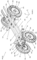
- FIGS 1 to 9 show several examples of variable track chassis 100 for an agricultural machine 1000, such as an agricultural tractor or an agricultural trailer, according to the invention.
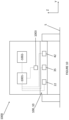
- FIG 10 shows an example of agricultural machine 1000 comprising the variable track chassis 100.
- a global reference is adopted without limitation comprising a longitudinal direction , and a vertical direction Z oriented from bottom to top.
- the longitudinal X and transverse Y directions are horizontal and substantially parallel to a ground S.
- the vertical direction Z is confused with the direction of the force of gravity of the agricultural spraying system 100.
- the vertical direction Z is inclined relative to the direction of the force of gravity of the agricultural spraying system 100.
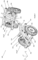
- the variable track chassis 100 comprises a fixed main chassis 11 as well as at least one assembly 10 itself comprising a pair of fixed guide bars 12a, 12b, a pair of chassis portions 13a, 13b, a first pair of supports wheel 14a, 14b, a first pair of suspension arms 15a, 15b, as well as a first pair of suspension systems 16a, 16b.
- the main chassis 11 supports for example a driver's cabin (not shown), and/or a tank (not shown) intended to contain treatment liquid, such as phytosanitary product or liquid fertilizer and a spraying system (not shown) intended to spray treatment liquid coming from the tank onto plants to be treated in a field.
- treatment liquid such as phytosanitary product or liquid fertilizer
- spraying system intended to spray treatment liquid coming from the tank onto plants to be treated in a field.
- the pair of guide bars 12a, 12b comprises a front guide bar 12a and a rear guide bar 12b on each of which the main frame 11 is fixed.
- the main frame 11 is for example fixed at two points on each of the front 12a and rear 12b guide bars, in particular at the ends of each front 12a and rear 12b guide bar.
- Each of the front 12a and rear 12b guide bars further extends along a generally transverse guide axis 17a, 17b.
- the front 12a and rear 12b guide bars are therefore parallel to each other and offset relative to each other in the longitudinal direction X, the front guide bar 12a being offset relative to the rear guide bar 12b towards the 'Before.
- the pair of frame portions 13a, 13b comprises a left frame portion 13a and a right frame portion 13b.
- Each of the left 13a and right 13b frame portions is slidably mounted on each of the front 12a and rear 12b guide bars along their respective guide axis 17a, 17b.
- the left chassis portion 13a is mounted on the left on the front 12a and rear 12b guide bars relative to the right chassis portion 13b, while the right chassis portion 13b is mounted on the right on the front guide bars 12a and rear 12b relative to the left chassis portion 13a.
- the left chassis portions 13a and right 13b are for example mounted on either side of a median plane, vertical and longitudinal, of the variable track chassis 100.
- the first pair of wheel supports 14a, 14b comprises a left wheel support 14a on which a first left wheel 18a is rotatably mounted, in particular around a first generally horizontal left axis of rotation 19a, and a right wheel support 14b on which a first right wheel 18b is rotatably mounted, in particular around a first generally horizontal straight axis of rotation 19b ( figures 1 to 3 ).
- the left 14a and right 14b wheel supports for example, each carry a motor, electric or hydraulic, respectively intended to drive the first left 18a and right 18b wheels in rotation around the first left rotation axes 19a and right 19b.
- the first pair of suspension arms 15a, 15b comprises a left suspension arm 15a and a right suspension arm 15b.
- the left 15a and right 15b suspension arms of the first pair are pivotally mounted on one of the front 12a and rear 12b guide bars, around the guide axis 17a, 17b of said front 12a or rear 12b guide bar .
- the left 15a and right 15b suspension arms of the first pair are also slidably mounted on said front 12a or rear 12b guide bar, along the guide axis 17a, 17b of said front guide bar 12a or rear 12b.
- a sliding pivot connection is thus provided between each of the left 15a and right 15b suspension arms of the first pair and said front 12a or rear 12b guide bar.
- the left suspension arm 15a of the first pair is mounted on the left on said front 12a or rear 12b guide bar relative to the right suspension arm 15b of the first pair, while the right suspension arm 15b is mounted on the right on said front 12a or rear 12b guide bar relative to the left suspension arm 15a.
- the left suspension arms 15a and right 15b of the first pair are for example mounted on either side of the median plane, vertical and longitudinal, of the variable track chassis 100.
- the left suspension arms 15a and right 15b of the first pair are thus mounted pivoting and sliding on the same front guide bar 12a or rear 12b of the first pair.
- the left wheel supports 14a and right 14b of the first pair are also respectively pivotally mounted on the left suspension arm 15a and the right suspension arm 15b of the first pair, around a generally vertical pivot axis 20a, 20b ( figure 2 ).
- the first pair of suspension systems 16a, 16b includes a left suspension system 16a and a right suspension system 16b.
- the left suspension system 16a of the first pair is for example mounted between the left suspension arm 15a of the first pair and the left chassis portion 13a, extending along a first left suspension axis 161a, while the system right suspension arm 16b of the first pair is mounted between the right suspension arm 15b of the first pair and the right chassis portion 13b, extending along a first right suspension axis 161b ( figure 2 ).
- the left suspension systems 16a and right 16b of the first pair are further designed to compress, respectively along the first left suspension axis 161a, the left suspension arm 15a of the first part approaching the left chassis portion 13a , and along the first right suspension axis 161b, the right suspension arm 15b of the first part approaching the right chassis portion 15b, and to relax, respectively along the first left suspension axis 161a, the suspension arm left 15a deviating from the portion of left chassis 13a, and along the first right suspension axis 161b, the right suspension arm 15b moving away from the right chassis portion 15b.
- the left suspension system 16a of the first pair is mounted between the left suspension arm 15a of the first pair and the main frame 11, extending along a first left suspension axis 161a
- the suspension system right 16b of the first pair is mounted between the right suspension arm 15b of the first pair and the main frame 11, extending along a first right suspension axis 161b.
- the left suspension systems 16a and right 16b of the first pair are further designed to compress, respectively along the first left suspension axis 161a, the left suspension arm 15a approaching the main frame 11, and along the first axis of right suspension 161b, the right suspension arm 15b approaching the main chassis 11, and to relax, respectively along the first left suspension axis 161a, the left suspension arm 15a moving away from the main chassis 11, and following the first right suspension axis 161b, the right suspension arm 15b moving away from the main frame 11.
- the left 13a and right 13b chassis portions and the left 15a and right 15b suspension arms of the first pair are able to move in translation relative to the front 12a and rear 12b guide bars, generally following the direction transversal Y, to vary a transverse distance between the left 14a and right 14b wheel supports of the first pair and therefore between the first left 18a and right 18b wheels and thus allow different track configurations of the variable track chassis 100.
- the left 13a and right 13b chassis portions are transversely closest to each other and the left 15a and right 15b suspension arms of the first pair are transversely closest to each other, so that the transverse distance between the left 14a and right 14b wheel supports of the first pair and therefore between the first left 18a and right 18b wheels is the smallest.
- the left chassis portions 13a and right 13b are transversely furthest from each other and the left suspension arms 15a and right 15b of the first pair are transversely furthest from each other, so that the transverse distance between the left wheel supports 14a and right 14b of the first pair and therefore between the first left wheels 18a and right 18b is the highest.
- Any intermediate configuration ( figures 2 to 4 And 6 to 9 ) between narrow gauge and wide gauge configurations may also be permitted.
- the narrow track configuration is adopted for driving on the road
- the wide track configuration or intermediate track configurations are on the other hand adopted for driving in fields of plants to be treated.
- the assembly of the left 15a and right 15b suspension arms of the first pair, the left 14a and right 14b wheel supports of the first pair, as well as the left 16a and right 16b suspension systems of the first pair makes it possible to obtain an independent suspension for the first left wheels 18a and right 18b and therefore improve the handling of the agricultural machine 1000 whatever the track configuration of the variable track chassis 100.
- variable track chassis 100 also includes only a limited number of parts to manufacture and assemble. In addition, the assembly of the different parts together is simple. The implementation of the pair of left 12a and right 12b guide bars, as well as the left 13a and right 13b chassis portions mounted on the left 12a and right 12b guide bars also gives robustness to the variable track chassis 100 .
- the assembly 10 of the variable track chassis 100 for example also comprises a first pair of shock absorbers 21a, 21b comprising a left shock absorber 21a and a right shock absorber 21b ( figures 1 , 2 And 4 to 9 ).
- the left shock absorber 21a of the first pair is for example mounted between the left suspension arm 15a of the first pair and the left chassis portion 13a, extending along a first left damping axis 211a, while the right shock absorber 21b of the first pair is mounted between the right suspension arm 15b of the first pair and the right chassis portion 13b, extending along a first right damping axis 211b ( figure 2 ).
- the left shock absorber 21a of the first pair is mounted between the left suspension arm 15a of the first pair and the main frame 11, extending along a first left damping axis 211a
- the right shock absorber 21b of the first pair is mounted between the right suspension arm 15b of the first pair and the main chassis 11, extending along a first right damping axis 211b.
- the left shock absorber 21a and the right shock absorber 21b of the first pair are respectively designed to dampen compression and relaxation of the left suspension system 16a and the right suspension system 16b of the first pair, and therefore a movement of the arm.
- the left suspension system 16a of the first pair and the left shock absorber 21a of the first pair can be mounted independently of each other or separately between the left suspension arm 15a of the first pair and the portion left chassis 13a or the main chassis 11 ( figures 1 , 2 , 4 And 6 to 9 ), each of the left suspension system 16a and the left shock absorber 21a being mounted directly on the left suspension arm 15a on the one hand, and on the left chassis portion 13a or the main chassis 11 on the other hand.
- the first left suspension axis 161a and the first left damping axis 211a are not confused.
- the left suspension system 16a and the left shock absorber 21a can, however, be mounted together between the left suspension arm 15a of the first pair and the left chassis portion 13a or the main chassis 11 ( Figure 5 ), the first left suspension axis 161a and the first left damping axis 211a being combined.
- right suspension system 16b of the first pair and the right shock absorber 21b of the first pair which can be mounted independently or together between the right suspension arm 15b of the first pair and the right chassis portion 13b or the main chassis 11.
- variable track chassis 100 When the left 13a and right 13b chassis portions and the left 15a and right 15b suspension arms of the first pair occupy their first position, the variable track chassis 100 is in the narrow track configuration ( figures 1 And 5 ). On the contrary, when the left 13a and right 13b chassis portions and the left 15a and right 15b suspension arms of the first pair occupy their second position, the variable track chassis 100 is in the wide track configuration.
- the left 13a and right 13b chassis portions and the left 15a and right 15b suspension arms of the first pair can also occupy any position between the first and second positions.
- THE figure 2 , 4 , 6 , 8 And 9 show the left chassis portion 13a and the left suspension arm 15a of the first pair in their first position, and the right chassis portion 13b and the right suspension arm 15b of the first pair in their second position.
- the left 15a and right 15b suspension arms of the first pair are respectively integral in sliding with the left 13a and right 13b chassis portions. This makes it possible to simplify the assembly of the drive mechanism 22.
- Each of the left 13a and right 13b frame portions comprises for example a first pair of lugs 23 via which said left 13a or right 13b frame portion is slidably mounted on the same front 12a or rear 12b guide bar as the left suspension arm 15a and right 15b of the first pair ( figure 2 ).
- the ears 23 of the first pair of each of the left 13a and right 13b chassis portions are further offset relative to each other along the guide axis 17a, 17b of said front 12a or rear 12b guide bar , so as to define a free space between said ears 23.
- Each of the left 15a and right 15b suspension arms of the first pair is also slidably mounted on said guide bar 12a or rear 12b, between the ears 23 of the portion of left chassis 13a or right 13b which drives it in sliding, in the free space defined between said lugs 23.
- the left chassis portions 13a and right 13b thus respectively drive the left suspension arm 15a and the right suspension arm 15b by through their first pair of ears 23.
- the left 16a and right 16b suspension systems of the first pair are for example respectively mounted on the left chassis portion 13a and the right chassis portion 13b, via one of the lugs 23 of the first pair of said portion of left frame 13a or right 13, said ear 23 extending from the front 12a or rear 12b guide bar on which said ear 23 is mounted, towards the left 14a or right 14b wheel support of the first pair.
- the left 21a and right 21b shock absorbers of the first pair can also be respectively mounted on the left chassis portion 13a and the right chassis portion 13b, via said ear 23 of the first pair.
- the drive mechanism 22 comprises for example a pair of cylinders 24, 25 ( figure 2 And 3 ) of which one of the cylinders 24, 25 is mounted on one of the front 12a and rear 12b guide bars on the one hand, and on the left chassis portion 13a or the left suspension arm 15a of the first pair which is mounted on said front 12a or rear 12b guide bar on the other hand, and of which the other of the cylinders 24, 25 is mounted on one or the other of the front 12a and rear 12b guide bars on the one hand , and on the right chassis portion 13b or the right suspension arm 15b of the first pair which is mounted on said front guide bar 12a or rear 12b on the other hand.
- the mounting of the cylinders 24, 25 can thus be symmetrical or asymmetrical with respect to the median, longitudinal and vertical plane of the variable track chassis 100.
- the drive mechanism 22 comprises for example two pairs of cylinders 24, 25 ( figure 2 And 3 ).
- the cylinders 24 of one of the pairs being mounted on one of the front 12a or rear 12b guide bars on the one hand, and on the left chassis portion 13a or the left suspension arm 15a of the first pair which is mounted on said front guide bar 12a or rear 12b on the other hand.
- the cylinders 25 of the other pair are mounted on the other of the front 12a or rear 12b guide bars on the one hand and on the right chassis portion 13b or the right suspension arm 15b of the first pair which is mounted on said front 12a or rear 12b guide bar on the other hand.
- the mounting of the cylinders 24, 25 of each pair is thus symmetrical with respect to the median, longitudinal and vertical plane of the variable track chassis 100.
- the drive mechanism 22 comprises one or more cylinders mounted between the left 13a and right 13b chassis portions and/or between the left 15a and right 15b suspension arms of the first pair.
- the cylinders 24, 25 of the drive mechanism 22 are for example hydraulic. They can also be pneumatic or electric.
- the drive mechanism 22 is for example also designed to slide the left chassis portion 13a and/or the left suspension arm 15a of the first pair relative to the front 12a and rear 12b guide bars on the one hand, and the right chassis portion 13a and/or the right suspension arm 15b of the first pair relative to the front 12a and rear 12b guide bars, symmetrically.
- the left chassis portion 13a and the left suspension arm 15a of the first pair thus travel the same distance, in the opposite direction, as the right chassis portion 13a and the right suspension arm 15b of the first pair, when the portions of left 13a and right 13b chassis and the left 15a and right 15b suspension arms of the first pair slide along the front 12a and rear 12b guide bars between the first and second positions. This ensures the stability of the agricultural machine 1000 whatever the track configuration of the variable track chassis 100.
- an electronic control unit 1001 ( Figure 10 ) is for example designed to control the same sliding movement of the rods of the jacks 24, 25 of the or each pair relative to a cylinder of said jack 24, 25 in which said rod is slidably mounted.
- the control unit 1001 can be designed to control the same sliding movement of the rod of one of the cylinders 24, 25 of each pair relative to the cylinder of said cylinder 24, 25, one of the cylinders 24, 25 of each pair being itself designed to control, depending on the sliding movement of its rod relative to its cylinder, the sliding movement of the rod of the other of the cylinders 24, 25 of said pair relative to the cylinder of said other of the cylinders 24, 25, the cylinders 24, 25 of each pair thus forming a master-slave system.
- the control unit 1001 can control the cylinders 24, 25 either indirectly via a hydraulic or pneumatic circuit, when they are hydraulic or pneumatic, or directly, when they are electric.
- the assembly 10 of the variable track chassis 100 also includes a second pair of wheel supports 26a, 26b, a second pair of suspension arms 27a, 27b and a second pair of suspension systems 28a, 28b.
- the second pair of wheel supports 26a, 26b comprises a left wheel support 26a on which a second left wheel 29a is rotatably mounted, in particular around a second generally horizontal left axis of rotation 30a, and a right wheel support 26b on which a second right wheel 29b is rotatably mounted, in particular around a second generally horizontal right axis of rotation 30b ( figures 1 And 3 ).
- the left 26a and right 26b wheel supports for example, each carry a motor, electric or hydraulic, respectively intended to drive the second left wheels 29a and right 29b in rotation around the second left axes of rotation 30a and right 30b.
- the second pair of suspension arms 27a, 27b comprises a left suspension arm 27a and a right suspension arm 27b.
- the left 27a and right 27b suspension arms of the second pair are pivotally mounted on the other of the front 12a or rear 12b guide bars, around the guide axis 17a, 17b of said front 12a or rear 12b guide bar .
- the left 27a and right 27b suspension arms of the second pair are further slidably mounted on said front 12a or rear 12b guide bar along the guide axis 17a, 17b of said front 12a or rear 12b guide bar.
- a sliding pivot connection is thus provided between each of the left 27a and right 27b suspension arms of the second pair and said front 12a or rear 12b guide bar.
- the left suspension arm 27a of the second pair is mounted on the left on said front 12a or rear 12b guide bar relative to the right suspension arm 27b of the second pair, while the right suspension arm 27b is mounted to the right on said front 12a or rear 12b guide bar relative to the left suspension arm 27a.
- the left suspension arms 27a and right 27b of the second pair are for example mounted on either side of the median plane, vertical and longitudinal, of the variable track chassis 100.
- the left suspension arms 27a and right 27b of the second pair are thus mounted pivoting and sliding on the same rear 12b or front 12a guide bar, which is different from that on which the left 15a and right 15b suspension arms of the first pair are mounted.
- the left 26a and right 26b wheel supports of the second pair are also respectively pivotally mounted on the left suspension arm 27a and the right suspension arm 27b of the second pair, around a generally vertical pivot axis 31a, 31b ( Figure 3 ).
- the second pair of suspension systems 28a, 28b includes a left suspension system 28a and a right suspension system 28b.
- the left suspension system 28a of the second pair is for example mounted between the left suspension arm 27a of the second pair and the left chassis portion 13a, extending along a second left suspension axis 281a, while the system right suspension arm 28b of the second pair is mounted between the right suspension arm 27b of the second pair and the right chassis portion 13b, extending along a second right suspension axis 281b ( Figure 3 ).
- the left suspension systems 28a and right 28b of the second pair are further designed to compress, respectively along the second left suspension axis 281a, the left suspension arm 27a of the second pair approaching the left chassis portion 13a , and along the second right suspension axis 281b, the right suspension arm 27b of the second pair approaching the right chassis portion 15b, and to relax, respectively along the second left suspension axis 281a, the suspension arm left 27a moving away from the left chassis portion 13a, and along the second right suspension axis 281b, the right suspension arm 27b moving away from the right chassis portion 15b.
- the left suspension system 28a of the second pair is mounted between the left suspension arm 27a of the second pair and the main frame 11, extending along a second left suspension axis 281a
- the suspension system right 28b of the second pair is mounted between the right suspension arm 27b of the second pair and the main frame 11, extending along a second right suspension axis 281b.
- the left suspension systems 28a and right 28b of the second pair are further designed to compress, respectively along the second left suspension axis 281a, the left suspension arm 27a of the second pair approaching the main frame 11, and following the second right suspension axis 281b, the right suspension arm 27b of the second pair approaching the main frame 11, and to relax, respectively along the second left suspension axis 281a, the left suspension arm 27a moving away from the main frame 11, and along the second right suspension axis 281b, the right suspension arm 27b moving away from the main frame 11.
- the left 13a and right 13b chassis portions, the left 15a and right 15b suspension arms of the first pair and the left 27a and right 27b suspension arms of the second pair are capable of moving in translation relative to each other.
- the front 12a and rear 12b guide bars, generally in the transverse direction Y to vary a transverse distance between the left 14a and right 14b wheel supports of the first pair and between the left 26a and right 26b wheel supports of the second pair, and therefore between the first left wheels 18a and right 18b and between the second left wheels 29a and right 29b, and thus allow the different track configurations of the variable track chassis 100.
- the left 13a and right 13b chassis portions are transversely closest to each other, the left 15a and right 15b suspension arms of the first pair are transversely closest to each other and the left 27a and right 27b suspension arms of the second pair are transversely as close as possible to each other, so that on the one hand, the transverse distance between the left 14a and right 14b wheel supports of the first pair and therefore between the first left wheels 18a and right 18b is the smallest, and on the other hand the transverse distance between the left 26a and right wheel supports 26b of the second pair and therefore between the second left and right wheels 29a 29b is the weakest.
- the left 13a and right 13b chassis portions are transversely the furthest from each other, the left 15a and right 15b suspension arms of the first pair are transversely the furthest apart from each other and the left suspension arms 27a and right 27b of the second pair are transversely furthest from each other, so that on the one hand, the transverse distance between the wheel supports left 14a and right 14b of the first pair and therefore between the first left wheels 18a and right 18b is the highest, and on the other hand, the transverse distance between the left wheel supports 26a and right 26b of the second pair and therefore between the second left wheels 29a and right 29b is the highest.
- Any intermediate configuration ( figures 2 to 4 And 6 ) between narrow gauge and wide gauge configurations is also permitted.
- the assembly of the left suspension arms 15a, 27a and right 15b, 27b of the first and second pairs, the left wheel supports 14a, 26a and right 14b, 26b of the first and second pairs, as well as the left suspension systems 16a, 28a and right 16b, 28b of the first and second pairs makes it possible to obtain independent suspension for each of the first and second left wheels 18a, 29a and right 18b, 29b and therefore to improve the handling of the agricultural machine 1000 regardless of the track configuration of the 100 variable track chassis.
- the assembly 10 of the variable track chassis 100 for example also comprises a second pair of shock absorbers 32a, 32b comprising a left shock absorber 32a and a right shock absorber 32b ( figures 3 And 5 ).
- the left shock absorber 32a of the second pair is for example mounted between the left suspension arm 27a of the second pair and the left chassis portion 13a, extending along a second left damping axis 321a, while the right shock absorber 32b of the second pair is mounted between the right suspension arm 27b of the second pair and the right chassis portion 13b, extending along a second right damping axis 321b ( figures 1 to 4 And 6 ).
- the left shock absorber 32a of the second pair is mounted between the left suspension arm 27a of the second pair and the main chassis 11, extending along a second left damping axis 321a
- the right shock absorber 32b of the second pair is mounted between the right suspension arm 27b of the second pair and the main frame 11, extending along a second right damping axis 321b.
- the left suspension system 28a of the second pair and the left shock absorber 32a of the second pair can be mounted independently of each other or separately between the left suspension arm 27a of the second pair and the portion left chassis 13a or the main chassis 11 ( figures 1 , 3 , 4 And 6 ), each of the left suspension system 28a and the left shock absorber 32a being mounted directly on the left suspension arm 27a on the one hand, and on the left chassis portion 13a or the main chassis 11 on the other hand.
- the second left suspension axis 281a and the second left damping axis 321a are not confused.
- the left suspension system 28a and the left shock absorber 32a can, however, be mounted together between the left suspension arm 27a of the second pair and the left chassis portion 13a or the main chassis 11 ( figure 5 ), the second left suspension axis 281a and the second left damping axis 321a being combined.
- right suspension system 28b of the second pair and the right shock absorber 32b of the second pair which can be mounted independently or together between the right suspension arm 27b of the second pair and the chassis portion. right 13b or the main frame 11.
- variable track chassis 100 When the left 13a and right 13b chassis portions and the left 15a, 27a and right 15b, 27b suspension arms of the first and second pairs occupy their first position, the variable track chassis 100 is in the narrow track configuration ( figures 1 And 5 ). On the contrary, when the left 13a and right 13b chassis portions and the left 15a, 27a and right 15b, 27b suspension arms of the first and second pairs occupy their second position, the variable track chassis 100 is in the wide track configuration .
- the left 13a and right 13b chassis portions and the left 15a, 27a and right 15b, 27b suspension arms of the first and second pairs can also occupy any position between the first and second positions.
- THE figures 2 , 3 , 4 , 6 , 8 And 9 show the left chassis portion 13a, the left suspension arm 15a of the first pair and the left suspension arm 27a of the second pair in their first position, and the right chassis portion 13b, the right suspension arm 15b of the first pair and the right suspension arm 27b of the second pair in their second position.
- the left suspension arms 15a, 27a of the first and second pairs and the right suspension arms 15b, 27b of the first and second pairs are respectively integral in sliding with the left chassis portions 13a and right 13b. This makes it possible to simplify the assembly of the drive mechanism 22.
- Each of the left 13a and right 13b frame portions comprises for example, in addition to the first pair of ears 23 already described, a second pair of ears 33 by means of which said left 13a or right 13b frame portion is mounted sliding on the same front 12a or rear 12b guide bar as the left 27a and right 27b suspension arms of the second pair ( Figure 3 ).
- the ears 33 of the second pair of each of the left 13a and right 13b chassis portions are further offset relative to each other along the guide axis 17a, 17b of said front 12a or rear 12b guide bar , so as to define a free space between said ears 33.
- Each of the left 27a and right 27b suspension arms of the second pair is also slidably mounted on said guide bar 12a or rear 12b, between the ears 33 of the second pair of the left chassis portion 13a or right 13b which causes it to slide, in the free space defined between said lugs 33.
- the left chassis portions 13a and right 13b thus respectively drive the left suspension arm 27a and the suspension arm.
- right suspension 27b of the second pair via their second pair of ears 33.
- the left 28a and right 28b suspension systems of the second pair are for example respectively mounted on the left chassis portion 13a and the right chassis portion 13b, via one of the lugs 33 of the second pair of said left 13a or right 13b chassis portion, said ear 33 extending from the front 12a or rear 12b guide bar on which said ear 23 is mounted, towards the left 26a or right 26b wheel support of the second pair.
- the left 32a and right 32b shock absorbers of the second pair can also be respectively mounted on the left chassis portion 13a and the right chassis portion 13b, via said ear 33 of the second pair.
- the drive mechanism 22 comprises for example at least one pair of cylinders 24, 25 ( figures 1 And 2 ).
- One of the cylinders 24, 25 is mounted on one of the front 12a and rear 12b guide bars on the one hand, and on the left chassis portion 13a or the left suspension arm 15a, 27a of the first or second pair which is mounted on said front 12a or rear 12b guide bar on the other hand.
- the other of the cylinders 24, 25 is mounted on one or the other of the front 12a and rear 12b guide bars on the one hand, and on the right chassis portion 13b or the right suspension arm 15b, 27b of the first or second pair which is mounted on said front guide bar 12a or rear 12b on the other hand.
- the mounting of the cylinders 24, 25 of the or each pair can thus be symmetrical or asymmetrical with respect to the median, longitudinal and vertical plane, of the variable track chassis 100.
- the drive mechanism 22 comprises for example two pairs of cylinders 24, 25.
- One of the cylinders 24 of a first pair is mounted on one of the front 12a and rear 12b guide bars on the one hand, and on the left chassis portion 13a or the left suspension arm 15a, 27a of the first pair or the second pair which is mounted on said front 12a or rear 12b guide bar on the other hand.
- the other of the cylinders 24 of the first pair is mounted on said front guide bar 12a or rear 12b on the one hand, and on the right chassis portion 13b or the right suspension arm 15a, 27a of the first pair or the second pair which is mounted on said front guide bars 12a or rear 12b on the other hand.
- One of the cylinders 25 of a second pair is mounted on the other of the front 12a and rear 12b guide bars on the one hand, and on the left chassis portion 13a or the left suspension arm 15a, 27a of the first pair or of the second pair which is mounted on said front guide bar 12a or rear 12b on the other hand, while the other of the cylinders 25 of the second pair is mounted on said front guide bar 12a or rear 12b d on the one hand, and on the right chassis portion 13b or the right suspension arm 15a, 27a of the first pair or the second pair which is mounted on said front guide bar 12a or rear 12b on the other hand.
- the mounting of the cylinders 24, 25 is thus symmetrical with respect to the median, longitudinal and vertical plane of the variable track chassis 100.
- the drive mechanism 22 comprises one or more cylinders mounted between the left 13a and right 13b chassis portions and/or between the left 15a and right 15b suspension arms of the first pair and/or between the left suspension arms 27a and right 27b of the second pair.
- the drive mechanism 22 is for example also designed to slide the left chassis portion 13a and/or the left suspension arm 15a of the first pair and/or the right suspension arm 27a of the second pair relative to the front 12a and rear 12b guide bars on the one hand, and the right chassis portion 13a and/or the right suspension arm 15b of the first pair and/or the right suspension arm 27b of the second pair relative to the bars front guide 12a and rear 12b, symmetrically.
- the left chassis portion 13a and the left suspension arms 15a, 27a of the first and second pairs thus travel the same distance, in the opposite direction, as the right chassis portion 13a and the right suspension arms 15b, 27a of the first and second pairs, when the left 13a and right 13b chassis portions and the left 15a, 27a and right 15b, 27b suspension arms slide along the front 12a and rear 12b guide bars between the first and second positions. This ensures the stability of the agricultural machine 1000 whatever the track configuration of the variable track chassis 100.
- an electronic control unit 1001 ( Figure 10 ) is for example designed to control the same sliding movement of the rods of the jacks 24, 25 of the or each pair relative to a cylinder of said jack 24, 25 in which said rod is slidably mounted.
- the control unit 1001 can be designed to control the same sliding movement of the rod of one of the cylinders 24, 25 of each pair relative to the cylinder of said cylinder, one of the cylinders 24, 25 of each pair being -even designed to control, as a function of the sliding movement of its rod relative to its cylinder, the sliding movement of the rod of the other of the jacks 24, 25 of said pair relative to the cylinder of said other of the jacks 24, 25, the cylinders 24, 25 of each pair thus forming a master-slave system.
- the control unit 1001 can control the cylinders 24, 25 either indirectly via a hydraulic or pneumatic circuit, when they are hydraulic or pneumatic, or directly, when they are electric.
- the main frame 11 includes a front frame part 11a and a rear frame part 11b articulated on the front chassis part 11a around a substantially vertical hinge axis 34.
- the front 11a and rear 11b frame parts are offset relative to each other in the longitudinal direction X, the front frame part 11a being offset relative to the rear frame part 11b towards the front.
- the hinge pin 34 is also longitudinally interposed between the front 11a and rear 11b chassis parts.
- the variable track chassis 100 further comprises two assemblies 10, referenced 10' and 10" ( Figure 7 ), each of the assemblies 10, 10', 10" comprising the front 12a and rear 12b guide bars, the left 13a and right 13b chassis portions, the first pair of wheel supports 14a, 14b, the first pair of control arms suspension 15a, 15b, the first pair of suspension systems 16a, 16b and, where appropriate, the first left 18a and right wheels 18b and/or the first pair of shock absorbers 21a, 21b and/or the drive mechanism 22
- the longitudinal and transverse orientations given for each of these components 13a, 13b, 14a, 14b, 15a, 15b, 16a, 16b, 18a, 18b, 21a, 21b, 22 are to be considered when the part.
- front frame 11a and the frame part 11b are longitudinally aligned with each other, their front 12a and rear 12b guide bars then all being oriented transversely.
- the assemblies 10, 10', 10" can implement the same or different embodiment variants.
- the front 12a and rear 12b guide bars of one of the assemblies 10, 10', 10" are fixed on one of the front 11a and rear 11b frame parts of the main frame 11, while the front guide bars 12a and rear 12b of the other of the assemblies 10, 10', 10" are fixed on the other of the front 11a and rear 11b frame parts of the main frame 11.
- the front frame part 11a is for example fixed at two points on each of the front 12a and rear 12b guide bars of one of the assemblies 10, 10', 10", in particular at the ends of each of said front 12a and rear 12b guide bars.
- the rear chassis part 11b is for example fixed in two points on each of the front 12a and rear 12b guide bars of the other of the assemblies 10, 10', 10", in particular at the ends of each of said front 12a and rear 12b guide bars.
- the left suspension systems 16a and right 16b of the first pair of one of the assemblies 10, 10', 10" are respectively mounted between the left suspension arms 15a and right 15b of the first pair of the one of the assemblies 10, 10', 10" and one of the front 11a and rear 11b chassis parts of the main chassis 11, extending respectively along the first left suspension axis 161a and the first right suspension axis 161b, while the left suspension systems 16a and right 16b of the first pair of the other of the assemblies 10, 10', 10" are respectively mounted between the left suspension arms 15a and right 15b of the first pair of the other of the sets 10, 10', 10" and the other of the front 11a and rear 11b frame parts of the main frame 11, extending respectively along the first left suspension axis 161a and the first right suspension axis 161b.
- the left 21a and right 21b shock absorbers of the first pair of one of the assemblies 10 are respectively mounted between the left 15a and right 15b suspension arm of the first pair of one of the assemblies 10, 10', 10" and one of the front 11a and rear 11b chassis parts of the main chassis 11, extending along their first left 211a and right 211b damping axis
- the left 21a and right 21b shock absorbers of the first pair on the other of the assemblies 10, 10', 10" are respectively mounted between the left suspension arm 15a and right 15b of the first pair of the other of the assemblies 10, 10', 10” and the other of the parts of front chassis 11a and rear 11b of the main chassis 11, extending along their first left 211a and right 211b damping axis.
- the two assemblies 10, 10', 10" thus operate in the same way.
- the left chassis portions 13a and right 13b of each assembly 10, 10', 10" and the left suspension arms 15a and 15b of each assembly 10, 10', 10" are capable of moving in translation relative to the front 12a and rear 12b guide bars of each assembly 10, 10', 10", generally in the transverse direction Y, to vary a transverse distance between the supports left wheel 14a and right 14b of each set 10, 10', 10" and therefore between the first left wheels 18a and right 18b of each set 10, 10', 10" and thus allow the different track configurations of the track chassis variable 100.
- the assembly of the left suspension arms 15a and right 15b of each assembly 10, 10', 10", of the left wheel supports 14a and right 14b of each assembly 10, 10', 10", as well as the suspension systems left 16a and right 16b suspension of each set 10, 10', 10" makes it possible to obtain an independent suspension for each of the first left wheels 18a and right 18b of the sets 10, 10', 10" and therefore to improve the resistance of road of the agricultural machine 1000 whatever the track configuration of the variable track chassis 100.
- Each of the assemblies 10, 10', 10" may further comprise the second pair of wheel supports 26a, 26b, the second pair of suspension arms 27a, 27b, the second pair of suspension systems 28a, 28b and, where appropriate , the second left wheels 29a and right 29b and/or the second pair of shock absorbers 32a, 32b, so as to obtain a variable track chassis 100 for eight-wheeled agricultural machine 1000 Of course, in this case too, the orientations.
- the left suspension systems 28a and right 28b of the second pair of one of the assemblies 10, 10', 10" are respectively mounted between the left suspension arms 27a and right 27b of the second pair of the one of the assemblies 10, 10', 10" and one of the front 11a and rear 11b chassis parts of the main chassis 11, extending respectively along the second left suspension axis 281a and the second right suspension axis 281b, while the left suspension systems 28a and right 28b of the second pair of the other of the assemblies 10, 10', 10" are respectively mounted between the left suspension arms 27a and right 27b of the second pair of the other of the sets 10, 10', 10" and the other of the front 11a and rear 11b frame parts of the main frame 11, extending respectively along the second left suspension axis 281a and the second right suspension axis 281b.
- the left shock absorbers 32a and right 32b of the second pair of one of the assemblies 10, 10', 10" are respectively mounted between the arms of left suspension 27a and right 27b of the second pair of one of the assemblies 10, 10', 10" and one of the front 11a and rear 11b chassis parts of the main chassis 11, extending along their second axis d left damping 321a and right 321b, while the left shock absorbers 32a and right 32b of the second pair of the other of the assemblies 10, 10', 10" are respectively mounted between the left suspension arms 27a and right 27b of the second pair of the other of the assemblies 10 and the other of the front 11a and rear 11b frame parts of the main frame 11, extending along their left 322a and right 322b extension axis.
- the front 12a and rear 12b guide bars of the assembly 10 or of each assembly 10, 10', 10" are for example arranged longitudinally on each side of the left 14a and right wheel supports 14b of the first pair ( figures 7 And 9 ).
- the front 12a and rear 12b guide bars are arranged longitudinally on the same side of the left 14a and right 14b wheel supports of the first pair, for example at the front of said left 14a and right 14b wheel supports.
- the front 12a and rear 12b guide bars are longitudinally arranged between the left 14a and right 14b wheel supports of the first pair and the left 26a and right 26b wheel supports of the second pair.
- the front 12a and rear 12b guide bars are arranged longitudinally on each side of the left wheel supports 14a, 26a and right 14b, 26b of the first and second pairs, the left wheel supports 14a, 26a and straight 14b, 26b of the first and second pairs thus being interposed between the front 12a and rear 12b guide bars.
- one of the front 14a and rear 14b guide bars is arranged between the left 14a, 26a and right 14b, 26b wheel supports of the first and second pairs, while the other of the guide bars front 12a and rear 12b guidance is arranged in front of or behind the left wheel supports 14a, 26a and right 14b, 26b of the first and second pairs.
- the or at least one of the assemblies 10, 10', 10" of the variable track chassis 100 may also comprise a first anti-tilting device 35 capable of pivotally securing the left suspension arm 15a and the suspension arm right 15b of the first pair or the left suspension arm 27a and the right suspension arm 27b of the second pair relative to the front 12a or rear 12b guide bar on which said left 15a, 27a and right 15b, 27a suspension arms are mounted, when said left 15a, 27a and right 15b, 27a suspension arms each occupy their own first position ( figure 2 ).
- a first anti-tilting device 35 capable of pivotally securing the left suspension arm 15a and the suspension arm right 15b of the first pair or the left suspension arm 27a and the right suspension arm 27b of the second pair relative to the front 12a or rear 12b guide bar on which said left 15a, 27a and right 15b, 27a suspension arms are mounted, when said left 15a, 27a and right 15b, 27a suspension arms each occupy their own first position ( figure 2 ).
- the first anti-tilt device 35 thus makes it possible to synchronize the pivoting of the left 15a and right 15b suspension arms of the first pair or of the left 27a and right 27b suspension arms of the second pair relative to the front guide bar 12a or rear 12b on which they are mounted, and thus to eliminate the independence of the suspension of the first left 18a and right 18 wheels or of the second left 29a and right 29b wheels, when the variable track chassis 100 is in track configuration narrow.
- This synchronization in the narrow track configuration of the variable track chassis makes it possible to avoid tilting of the agricultural machine 1000, when it is rolling on a slope, the first left wheels 18a and right 18b and/or the second left wheels 29a and right 29b not being at the same height from each other, or when driving at high speed around a roundabout.
- the or at least one of the assemblies 10, 10', 10" of the variable track chassis 100 may comprise two first anti-tilt devices 35, one of the first anti-tilt devices 35 being able to secure in pivoting the left suspension arm 15a and the right suspension arm 15b of the first pair relative to the front 12a or rear 12b guide bar on which said left suspension arms 15a and right 15b of the first pair are mounted, the other of the first anti-tilt devices 35 being able to pivotally secure the left suspension arm 27a and the right suspension arm 27b of the second pair relative to the front 12a or rear 12b guide bar on which said arms left 27a and right 27a suspension arms of the second pair are mounted, when said left 15a, 27a and right 15b, 27a suspension arms each occupy their first position.
- the or each first anti-tilt device 35 comprises a female coupling part 36 carried by one of the left suspension arm 15a and the right suspension arm 15b of the first pair or the suspension arm left 27a and the right suspension arm 27b of the second pair, and a male coupling part 37 carried by the other among the left suspension arm 15a and the right suspension arm 15b of the first pair or the left suspension arm 27a and the right suspension arm 27b of the second pair.
- the female coupling part 36 comprises an opening 38 extending around a coupling axis 39, generally transverse, parallel to the guide axes 17a, 17b of the front 12a and rear 12b guide bars and also giving access to housing.
- the male coupling part 37 comprises a finger 40 extending along the coupling axis 39, said finger 40 being able to be inserted into the housing of the female coupling part 36, through the opening 38, when the left suspension arms 15a and right 15b of the first pair slide from their second position to their first position or they each occupy their first position.
- either the pivoting of the left suspension arms 15a, 27a and right 15b, 27b of the first pair or the second pair is synchronized as soon as the variable track chassis 100 is in narrow track configuration, or this synchronization can be activated , by inserting the finger 40 into the housing, and deactivated, by removing the finger 40 from the housing, when the variable track chassis 100 is in narrow track configuration.
- the male coupling part 37 comprises for example an actuator 41 designed to drive the finger 40 in translation along the coupling axis 39, relative to the left suspension arm 15a, 27a or right 15b, 27b of the first or the second pair which carries the male coupling part 37, between an active position in which the finger 40 occupies the housing of the female coupling part 36 and an inactive position in which the finger 40 releases the housing of the female part d coupling 36, when the left suspension arms 15a, 27a and right 15b, 27b of the first pair or the first and second pairs each occupy their first position.
- the finger 40 is for example itself slidably mounted, along the coupling axis 39, in a sleeve 411 formed in the left suspension arm 15a, 27a or right 15b, 27b of the first or second pair which carries the male coupling part 37.
- the cylinder forming the actuator 41 of the male coupling part 37 is for example hydraulic. It can also be pneumatic or electric.
- An electronic control unit 1001 ( Figure 10 ) is for example designed to control the actuator 41 to move the finger 40 in translation between the active and inactive positions, in particular by controlling the sliding movement of the rod relative to the cylinder of the jack forming the actuator 41 of the male part coupling 37 between the extended and retracted positions.
- the control unit 1001 can control the cylinder forming the actuator 41 either indirectly via a hydraulic or pneumatic circuit, when it is hydraulic or pneumatic, or directly, when it is electric.
- the control unit 1001 can also be designed to control the actuator 41 to move the finger 40 from the inactive position to the active position, in particular by controlling the sliding movement of the rod relative to the cylinder of the cylinder forming the actuator 41 of the male coupling part 37 from the retracted position to the extended position, when an inclinometer 1003 ( Figure 10 ) mounted on the agricultural machine 1000, for example on the variable track chassis 100, measures an angle of inclination between the vertical direction Z and a direction of the force of gravity applied to the agricultural machine 1000, greater than or equal to a first predetermined angle of inclination, and to control the actuator 41 to move the finger 40 from the active position to the inactive position, in particular by controlling the sliding movement of the rod relative to the cylinder of the cylinder forming the actuator 41 of the male coupling part 37 from the extended position to the retracted position, when the angle of inclination measured by the inclinometer 1003 is less than the first predetermined angle of inclination.
- the control unit 1001 is for example designed to selectively control the actuators 41 of both of the first anti-tilting devices 35, so that the pivoting of the left suspension arms 15a and right 15b of the first pair and that of the left suspension arms 27a and right 27b of the second pair cannot be synchronized at the same time.
- the control unit 1001 can still be designed to only control the actuator 41 of the first anti-tilt device 35 which is arranged as close as possible to the front guide bar. 12a or rear 12b supporting the most weight of the agricultural machine 1000, said front 12a or rear 12b guide bar being able to be previously defined by the farmer via the user interface 1002 or by means of weight sensors communicating with the control unit 1001.
- the or each assembly 10, 10', 10" of the variable track chassis 100 may also include second anti-tilting devices 42 ( figure 2 ).
- Each second anti-tilt device 42 is mounted on the one hand, on one of the suspension arms 15a, 27a, 15b, 27b among the left suspension arms 15a, 27a and right 15b, 27b of the first pair or of the first and second pairs, and on the other hand, on the left chassis portion 13a or 13b on which said suspension arm 15a, 27a, 15b, 27b is mounted or on the fixed chassis 11 or on the part of front chassis 11a or rear 11b of the same assembly 10, 10', 10" as said suspension arm 15a, 27a, 15b, 27b.
- the second anti-tilt device 42 is thus mounted on the suspension arm 15a, 27a, 15b, 27b in parallel with the left suspension system 16a, 28a or right 16b, 28b and/or the left shock absorber 21a, 32a or straight 21b, 32b which are mounted on the same suspension arm 15a, 27a, 15b, 27b as the second anti-tilt device 42.
- the second anti-tilt device 42 thus makes it possible to limit the relaxation of said left suspension system 16a, 28a or right 16b, 28b and therefore a maximum distance travel between the suspension arm 15a, 27a, 15b, 27b and the left chassis portion 13a or right 13b on which said suspension arm 15a, 27a, 15b, 27b is mounted either the main chassis 11 or the front chassis part 11a or rear 11b of the same assembly 10, 10', 10" as said suspension arm 15a, 27a, 15b, 27b.
- the downstream frame portion 13a, 13b supports more weight than the upstream frame portion 13b, 13a, so the system(s) of left suspensions 16a, 28a or right 16b, 28b arranged on the side of the downstream chassis portion 13a, 13b compress, while the left suspension system(s) 16a, 28a or right 16b, 28b arranged on the side of the chassis portion upstream 13b, 13a relax, which has the effect of further transferring the weight of the agricultural machine 1000 from the upstream chassis portion 13b, 13a to the downstream chassis portion 13a, 13b and can thus cause a tilting of the agricultural machine 1000.
- the second anti-tilt device 42 can also occupy any intermediate position between the maximum and minimum or zero stress positions, the second anti-tilt device 42 then constraining a maximum extension length of said left suspension system 16a, 28a or straight 16b, 28b at a length between the first and second lengths or less than the first length.
- the second anti-tilting device 42 comprises for example an actuator 43 and a sling 44 comprising a first end 45 and a second opposite end 46.
- the actuator 43 of the second anti-tilt device 42 is further designed to tension the sling 44 from a relaxed position in which the second anti-tilt device 42 occupies the position of minimum or zero stress towards a tensioned position in in which the sling 45 is more tensioned than in the relaxed position and the second anti-tilting device 42 occupies the maximum stress position, and to relax the sling 45 from the tensioned position to the relaxed position.
- the actuator 43 of the second anti-tilt device 42 is for example formed by a cylinder comprising a rod and a cylinder, one of the rod or the cylinder being mounted on one of the suspension arm 15a, 27a , 15b, 27b and that of the front frame portion 13a or rear 13b, of the main frame 11 and of the front frame portion 11a or rear 11b on which the second anti-tilt device 42 is mounted, while the another of the cylinder and the rod is mounted on the first end 45 of the sling 44.
- the rod is further designed to slide in the cylinder between a retracted position in which the sling 44 occupies the tensioned position and an extended position in which one end of the cylinder rod, opposite the cylinder, is further from the cylinder than in the retracted position and the sling 44 occupies the relaxed position.
- the cylinder forming the actuator 43 of the second anti-tilting device 42 is for example hydraulic. It can also be pneumatic or electric.
- An electronic control unit 1001 ( Figure 10 ) is for example designed to control the actuator 43 of the or each second anti-tilting device 42 to tighten or relax the sling 44, in particular by controlling the sliding movement of the rod relative to the cylinder of the cylinder forming the actuator 43 between the extended and retracted positions.
- the control unit 1001 can control said cylinder either indirectly via a hydraulic or pneumatic circuit, when it is hydraulic or pneumatic, or directly, when it is electric.
- the control unit 1001 can further be designed to control the actuator 43 of the or each second anti-tilt device 42 to tension the sling 44 from the relaxed position to the relaxed position or to an intermediate position between the relaxed position and the tensioned position, and to relax the sling 44 from the tensioned position to the relaxed position or to an intermediate position between the tensioned position and the relaxed position, when the control unit 1001 receives a command sent by the farmer via a user interface 1002 ( Figure 10 ) connected to the control unit 1001.
- the user interface 1002 is for example arranged in the driver's cabin of the agricultural machine 1000.
- the control unit 1001 can also be designed to control the actuator 43 of the or each second anti-tilt device 42 to tension the sling 44 from the relaxed position to the tensioned position, when an inclinometer 1003 ( Figure 10 ) mounted on the agricultural machine 1000, for example on the variable track chassis 100, measures an angle of inclination between the vertical direction Z and a direction of the force of gravity applied to the agricultural machine 1000, greater than or equal to a second predetermined angle of inclination, and to control the actuator 43 to relax the sling 44 from the tensioned position to the relaxed position, when the angle of inclination measured by the inclinometer 1003 is less than the second angle of inclination predetermined inclination.
- the control unit 1001 can also be designed to control the actuator 43 of the or each second anti-tilt device 42 to tension and relax the sling 44, as a function of the angle of inclination measured by the the inclinometer 1003, the higher the angle of inclination measured, the more the sling 44 being tensioned by the actuator 43.
- any known suspension system can be implemented for the left suspension systems 16a, 28a and right suspension systems 16b, 28b of the first pair or the first and second pairs.
- These may be compression wire springs ( figures 1 to 3 , 8 And 9 ), pneumatic suspension systems, in particular with cushions or air lungs ( figures 4 And 7 ), or even hydraulic cylinders ( Figure 6 ).
- strut ( figure 5 ) extending along the first or second left suspension axis 161a, 281a or right 161b, 281b, the strut comprising a hydraulic or pneumatic cylinder forming the left 21a, 32a or right 21b, 32b shock absorber and extending along said first or second left suspension axis 161a, 281a or right 161b, 281b, then merged with the first or second left damping axis 21a, 32a or right 21b, 32b, as well as a compression wire spring or air lungs forming the left suspension system 16a, 28a or right 16b, 28b, the compression wire spring or the air lungs being mounted between two supporting faces of the strut, perpendicular to said first or second axis left suspension 161a, 281a or right 161b, 281b, around the hydraulic or pneumatic cylinder.
- any known shock absorber can be used for the left shock absorbers 21a, 32a and right shock absorbers 21b, 32b of the first pair or the first and second pairs.
- These are, for example, hydraulic cylinders or even pneumatic cylinders ( figures 1 to 4 And 5 to 9 ).
- variable track chassis 100 of the or of each assembly 10 for example also comprises a steering cylinder 47 mounted between each wheel support 14a, 26a, 14b, 26b among the left wheel supports 14a, 26a and right wheel supports 14b, 26b of the first pair or first and second pairs and the left suspension arm 15a, 27a or right 15b, 27b of the first or first and second pair on which said wheel support 14a, 26a, 14b, 26b is mounted, so as to rotate the wheel 18a, 18b, 29a, 29b among the first left wheels 18a and right 18b or the first and second left wheels 18a, 29a and right wheels 18b, 29b mounted on said wheel support 14a, 26a, 14b, 26b.
- a steering cylinder 47 mounted between each wheel support 14a, 26a, 14b, 26b among the left wheel supports 14a, 26a and right wheel supports 14b, 26b of the first pair or first and second pairs and the left suspension arm 15a, 27a or right 15b, 27b of the first or first and second pair on which said
- variable track chassis 100 is particularly advantageous because it is both simple to manufacture and assemble and robust. It also makes it possible to obtain independent suspension for each of the first and/or second wheels 18a, 18b, 29a, 29b whatever the track configuration of the variable track chassis 100.
Landscapes
- Engineering & Computer Science (AREA)
- Mechanical Engineering (AREA)
- Chemical & Material Sciences (AREA)
- Combustion & Propulsion (AREA)
- Transportation (AREA)
- Architecture (AREA)
- Structural Engineering (AREA)
- Vehicle Body Suspensions (AREA)
- Body Structure For Vehicles (AREA)
- Guiding Agricultural Machines (AREA)
Applications Claiming Priority (3)
| Application Number | Priority Date | Filing Date | Title |
|---|---|---|---|
| FR2007384A FR3112523B1 (fr) | 2020-07-15 | 2020-07-15 | Chassis a voie variable pour engin agricole |
| EP21749666.0A EP4182206B1 (de) | 2020-07-15 | 2021-07-09 | Fahrwerk mit variabler spurweite für landmaschinen |
| PCT/FR2021/051279 WO2022013494A1 (fr) | 2020-07-15 | 2021-07-09 | Chassis a voie variable pour engin agricole |
Related Parent Applications (2)
| Application Number | Title | Priority Date | Filing Date |
|---|---|---|---|
| EP21749666.0A Division EP4182206B1 (de) | 2020-07-15 | 2021-07-09 | Fahrwerk mit variabler spurweite für landmaschinen |
| EP21749666.0A Division-Into EP4182206B1 (de) | 2020-07-15 | 2021-07-09 | Fahrwerk mit variabler spurweite für landmaschinen |
Publications (2)
| Publication Number | Publication Date |
|---|---|
| EP4403385A2 true EP4403385A2 (de) | 2024-07-24 |
| EP4403385A3 EP4403385A3 (de) | 2024-10-30 |
Family
ID=72885721
Family Applications (2)
| Application Number | Title | Priority Date | Filing Date |
|---|---|---|---|
| EP21749666.0A Active EP4182206B1 (de) | 2020-07-15 | 2021-07-09 | Fahrwerk mit variabler spurweite für landmaschinen |
| EP24180029.1A Pending EP4403385A3 (de) | 2020-07-15 | 2021-07-09 | Fahrwerk mit veränderlicher spur für landwirtschaftliche arbeitsmaschine |
Family Applications Before (1)
| Application Number | Title | Priority Date | Filing Date |
|---|---|---|---|
| EP21749666.0A Active EP4182206B1 (de) | 2020-07-15 | 2021-07-09 | Fahrwerk mit variabler spurweite für landmaschinen |
Country Status (5)
| Country | Link |
|---|---|
| EP (2) | EP4182206B1 (de) |
| ES (1) | ES2991331T3 (de) |
| FR (1) | FR3112523B1 (de) |
| PL (1) | PL4182206T3 (de) |
| WO (1) | WO2022013494A1 (de) |
Family Cites Families (3)
| Publication number | Priority date | Publication date | Assignee | Title |
|---|---|---|---|---|
| FR2549434B1 (fr) * | 1983-07-22 | 1988-12-02 | Bobard Jeune Sa Ets | Chassis de tracteur enjambeur |
| US8042817B2 (en) * | 2009-12-22 | 2011-10-25 | Agco Corporation | Adjustable height device for high clearance vehicle |
| US9688113B2 (en) * | 2015-07-14 | 2017-06-27 | Cnh Industrial America Llc | System for adjusting frame height of an agricultural vehicle |
-
2020
- 2020-07-15 FR FR2007384A patent/FR3112523B1/fr active Active
-
2021
- 2021-07-09 ES ES21749666T patent/ES2991331T3/es active Active
- 2021-07-09 WO PCT/FR2021/051279 patent/WO2022013494A1/fr not_active Ceased
- 2021-07-09 EP EP21749666.0A patent/EP4182206B1/de active Active
- 2021-07-09 EP EP24180029.1A patent/EP4403385A3/de active Pending
- 2021-07-09 PL PL21749666.0T patent/PL4182206T3/pl unknown
Also Published As
| Publication number | Publication date |
|---|---|
| EP4403385A3 (de) | 2024-10-30 |
| FR3112523A1 (fr) | 2022-01-21 |
| FR3112523B1 (fr) | 2022-08-26 |
| ES2991331T3 (es) | 2024-12-03 |
| EP4182206C0 (de) | 2024-08-07 |
| EP4182206A1 (de) | 2023-05-24 |
| EP4182206B1 (de) | 2024-08-07 |
| WO2022013494A1 (fr) | 2022-01-20 |
| PL4182206T3 (pl) | 2024-12-16 |
Similar Documents
| Publication | Publication Date | Title |
|---|---|---|
| EP0458665B1 (de) | Hinterradaufhängung eines Kraftfahrzeugs | |
| EP0991316B1 (de) | Aufhängungsvorrichtung für spritzgestänge | |
| FR2536345A1 (fr) | Suspension a triangles superposes et angle de chasse variable pour vehicules | |
| FR2749265A1 (fr) | Vehicule a partie de caisse, notamment a cabine de conduite, suspendue elastiquement | |
| FR2796594A1 (fr) | Vehicule automobile equipe d'un systeme de controle de l'angle de carrossage des roues du vehicule en virage | |
| FR2636569A1 (de) | ||
| EP3318430B1 (de) | Stelzentraktor | |
| FR2588217A1 (fr) | Suspension de roue arriere independante | |
| EP1765615A1 (de) | Kraftfahrzeugfederungsvorrichtung | |
| FR2853281A1 (fr) | Essieu souple arriere a palonnier, et vehicule correspondant | |
| FR2879508A1 (fr) | Essieu suspendu pour vehicule | |
| EP1931527A1 (de) | Fahrzeugaufhängungsvorrichtung | |
| EP0494125A1 (de) | Boden- oder Vegetationsbehandlungsvorrichtung, mit einer um longitudinale und transversale Achsen schwenkbaren Rampe | |
| EP4182206B1 (de) | Fahrwerk mit variabler spurweite für landmaschinen | |
| FR2772308A1 (fr) | Essieu de vehicule | |
| FR2654574A1 (fr) | Dispositif stabilisateur de montage d'un outil agricole de largeur importante sur un appareil porteur. | |
| FR2813212A1 (fr) | Rampe de pulverisation perfectionnee | |
| FR2677928A1 (fr) | Demi-train de suspension de roue a triangles superposes. | |
| FR2738190A1 (fr) | Dispositif de suspension pour train de roues arriere de vehicule automobile | |
| FR2499001A1 (fr) | Vehicule a traction avant muni d'un dispositif de basculement facilitant son chargement | |
| FR2675431A1 (fr) | Dispositif de suspension de vehicule a jambe articulee. | |
| FR2536019A1 (fr) | Dispositif de correction d'assiette pour vehicule automobile | |
| EP0907520B1 (de) | Hinterachse für motorfahrzeug | |
| FR2730955A1 (fr) | Train arriere pour vehicule automobile | |
| FR2752213A1 (fr) | Perfectionnement pour chassis de vehicule |
Legal Events
| Date | Code | Title | Description |
|---|---|---|---|
| PUAI | Public reference made under article 153(3) epc to a published international application that has entered the european phase |
Free format text: ORIGINAL CODE: 0009012 |
|
| STAA | Information on the status of an ep patent application or granted ep patent |
Free format text: STATUS: THE APPLICATION HAS BEEN PUBLISHED |
|
| AC | Divisional application: reference to earlier application |
Ref document number: 4182206 Country of ref document: EP Kind code of ref document: P |
|
| AK | Designated contracting states |
Kind code of ref document: A2 Designated state(s): AL AT BE BG CH CY CZ DE DK EE ES FI FR GB GR HR HU IE IS IT LI LT LU LV MC MK MT NL NO PL PT RO RS SE SI SK SM TR |
|
| REG | Reference to a national code |
Ref country code: DE Ref legal event code: R079 Free format text: PREVIOUS MAIN CLASS: B60G0001000000 Ipc: B62D0049060000 |
|
| PUAL | Search report despatched |
Free format text: ORIGINAL CODE: 0009013 |
|
| AK | Designated contracting states |
Kind code of ref document: A3 Designated state(s): AL AT BE BG CH CY CZ DE DK EE ES FI FR GB GR HR HU IE IS IT LI LT LU LV MC MK MT NL NO PL PT RO RS SE SI SK SM TR |
|
| RIC1 | Information provided on ipc code assigned before grant |
Ipc: B60G 3/20 20060101ALI20240925BHEP Ipc: B60G 1/00 20060101ALI20240925BHEP Ipc: B62D 21/18 20060101ALI20240925BHEP Ipc: B62D 49/06 20060101AFI20240925BHEP |
|
| STAA | Information on the status of an ep patent application or granted ep patent |
Free format text: STATUS: REQUEST FOR EXAMINATION WAS MADE |
|
| 17P | Request for examination filed |
Effective date: 20250428 |
|
| STAA | Information on the status of an ep patent application or granted ep patent |
Free format text: STATUS: EXAMINATION IS IN PROGRESS |
|
| 17Q | First examination report despatched |
Effective date: 20260211 |