EP4403295A1 - Wire and welding member for gas-shielded arc welding having excellent fatigue resistance characteristics and resistance against deformation due to residual stress of welding zone, and manufacturing method therefor - Google Patents
Wire and welding member for gas-shielded arc welding having excellent fatigue resistance characteristics and resistance against deformation due to residual stress of welding zone, and manufacturing method therefor Download PDFInfo
- Publication number
- EP4403295A1 EP4403295A1 EP21957640.2A EP21957640A EP4403295A1 EP 4403295 A1 EP4403295 A1 EP 4403295A1 EP 21957640 A EP21957640 A EP 21957640A EP 4403295 A1 EP4403295 A1 EP 4403295A1
- Authority
- EP
- European Patent Office
- Prior art keywords
- welding
- weld zone
- less
- residual stress
- deformation due
- Prior art date
- Legal status (The legal status is an assumption and is not a legal conclusion. Google has not performed a legal analysis and makes no representation as to the accuracy of the status listed.)
- Pending
Links
Images




Classifications
-
- B—PERFORMING OPERATIONS; TRANSPORTING
- B23—MACHINE TOOLS; METAL-WORKING NOT OTHERWISE PROVIDED FOR
- B23K—SOLDERING OR UNSOLDERING; WELDING; CLADDING OR PLATING BY SOLDERING OR WELDING; CUTTING BY APPLYING HEAT LOCALLY, e.g. FLAME CUTTING; WORKING BY LASER BEAM
- B23K35/00—Rods, electrodes, materials, or media, for use in soldering, welding, or cutting
- B23K35/22—Rods, electrodes, materials, or media, for use in soldering, welding, or cutting characterised by the composition or nature of the material
- B23K35/24—Selection of soldering or welding materials proper
- B23K35/30—Selection of soldering or welding materials proper with the principal constituent melting at less than 1550°C
- B23K35/3053—Fe as the principal constituent
- B23K35/308—Fe as the principal constituent with Cr as next major constituent
- B23K35/3086—Fe as the principal constituent with Cr as next major constituent containing Ni or Mn
-
- B—PERFORMING OPERATIONS; TRANSPORTING
- B23—MACHINE TOOLS; METAL-WORKING NOT OTHERWISE PROVIDED FOR
- B23K—SOLDERING OR UNSOLDERING; WELDING; CLADDING OR PLATING BY SOLDERING OR WELDING; CUTTING BY APPLYING HEAT LOCALLY, e.g. FLAME CUTTING; WORKING BY LASER BEAM
- B23K35/00—Rods, electrodes, materials, or media, for use in soldering, welding, or cutting
- B23K35/02—Rods, electrodes, materials, or media, for use in soldering, welding, or cutting characterised by mechanical features, e.g. shape
-
- B—PERFORMING OPERATIONS; TRANSPORTING
- B23—MACHINE TOOLS; METAL-WORKING NOT OTHERWISE PROVIDED FOR
- B23K—SOLDERING OR UNSOLDERING; WELDING; CLADDING OR PLATING BY SOLDERING OR WELDING; CUTTING BY APPLYING HEAT LOCALLY, e.g. FLAME CUTTING; WORKING BY LASER BEAM
- B23K35/00—Rods, electrodes, materials, or media, for use in soldering, welding, or cutting
- B23K35/02—Rods, electrodes, materials, or media, for use in soldering, welding, or cutting characterised by mechanical features, e.g. shape
- B23K35/0255—Rods, electrodes, materials, or media, for use in soldering, welding, or cutting characterised by mechanical features, e.g. shape for use in welding
- B23K35/0261—Rods, electrodes or wires
-
- B—PERFORMING OPERATIONS; TRANSPORTING
- B23—MACHINE TOOLS; METAL-WORKING NOT OTHERWISE PROVIDED FOR
- B23K—SOLDERING OR UNSOLDERING; WELDING; CLADDING OR PLATING BY SOLDERING OR WELDING; CUTTING BY APPLYING HEAT LOCALLY, e.g. FLAME CUTTING; WORKING BY LASER BEAM
- B23K35/00—Rods, electrodes, materials, or media, for use in soldering, welding, or cutting
- B23K35/02—Rods, electrodes, materials, or media, for use in soldering, welding, or cutting characterised by mechanical features, e.g. shape
- B23K35/0255—Rods, electrodes, materials, or media, for use in soldering, welding, or cutting characterised by mechanical features, e.g. shape for use in welding
- B23K35/0261—Rods, electrodes or wires
- B23K35/0266—Rods, electrodes or wires flux-cored
-
- B—PERFORMING OPERATIONS; TRANSPORTING
- B23—MACHINE TOOLS; METAL-WORKING NOT OTHERWISE PROVIDED FOR
- B23K—SOLDERING OR UNSOLDERING; WELDING; CLADDING OR PLATING BY SOLDERING OR WELDING; CUTTING BY APPLYING HEAT LOCALLY, e.g. FLAME CUTTING; WORKING BY LASER BEAM
- B23K35/00—Rods, electrodes, materials, or media, for use in soldering, welding, or cutting
- B23K35/22—Rods, electrodes, materials, or media, for use in soldering, welding, or cutting characterised by the composition or nature of the material
- B23K35/24—Selection of soldering or welding materials proper
- B23K35/30—Selection of soldering or welding materials proper with the principal constituent melting at less than 1550°C
-
- B—PERFORMING OPERATIONS; TRANSPORTING
- B23—MACHINE TOOLS; METAL-WORKING NOT OTHERWISE PROVIDED FOR
- B23K—SOLDERING OR UNSOLDERING; WELDING; CLADDING OR PLATING BY SOLDERING OR WELDING; CUTTING BY APPLYING HEAT LOCALLY, e.g. FLAME CUTTING; WORKING BY LASER BEAM
- B23K35/00—Rods, electrodes, materials, or media, for use in soldering, welding, or cutting
- B23K35/22—Rods, electrodes, materials, or media, for use in soldering, welding, or cutting characterised by the composition or nature of the material
- B23K35/24—Selection of soldering or welding materials proper
- B23K35/30—Selection of soldering or welding materials proper with the principal constituent melting at less than 1550°C
- B23K35/3053—Fe as the principal constituent
-
- B—PERFORMING OPERATIONS; TRANSPORTING
- B23—MACHINE TOOLS; METAL-WORKING NOT OTHERWISE PROVIDED FOR
- B23K—SOLDERING OR UNSOLDERING; WELDING; CLADDING OR PLATING BY SOLDERING OR WELDING; CUTTING BY APPLYING HEAT LOCALLY, e.g. FLAME CUTTING; WORKING BY LASER BEAM
- B23K35/00—Rods, electrodes, materials, or media, for use in soldering, welding, or cutting
- B23K35/22—Rods, electrodes, materials, or media, for use in soldering, welding, or cutting characterised by the composition or nature of the material
- B23K35/24—Selection of soldering or welding materials proper
- B23K35/30—Selection of soldering or welding materials proper with the principal constituent melting at less than 1550°C
- B23K35/3053—Fe as the principal constituent
- B23K35/3066—Fe as the principal constituent with Ni as next major constituent
-
- B—PERFORMING OPERATIONS; TRANSPORTING
- B23—MACHINE TOOLS; METAL-WORKING NOT OTHERWISE PROVIDED FOR
- B23K—SOLDERING OR UNSOLDERING; WELDING; CLADDING OR PLATING BY SOLDERING OR WELDING; CUTTING BY APPLYING HEAT LOCALLY, e.g. FLAME CUTTING; WORKING BY LASER BEAM
- B23K35/00—Rods, electrodes, materials, or media, for use in soldering, welding, or cutting
- B23K35/22—Rods, electrodes, materials, or media, for use in soldering, welding, or cutting characterised by the composition or nature of the material
- B23K35/24—Selection of soldering or welding materials proper
- B23K35/30—Selection of soldering or welding materials proper with the principal constituent melting at less than 1550°C
- B23K35/3053—Fe as the principal constituent
- B23K35/3073—Fe as the principal constituent with Mn as next major constituent
-
- B—PERFORMING OPERATIONS; TRANSPORTING
- B23—MACHINE TOOLS; METAL-WORKING NOT OTHERWISE PROVIDED FOR
- B23K—SOLDERING OR UNSOLDERING; WELDING; CLADDING OR PLATING BY SOLDERING OR WELDING; CUTTING BY APPLYING HEAT LOCALLY, e.g. FLAME CUTTING; WORKING BY LASER BEAM
- B23K9/00—Arc welding or cutting
- B23K9/16—Arc welding or cutting making use of shielding gas
-
- B—PERFORMING OPERATIONS; TRANSPORTING
- B23—MACHINE TOOLS; METAL-WORKING NOT OTHERWISE PROVIDED FOR
- B23K—SOLDERING OR UNSOLDERING; WELDING; CLADDING OR PLATING BY SOLDERING OR WELDING; CUTTING BY APPLYING HEAT LOCALLY, e.g. FLAME CUTTING; WORKING BY LASER BEAM
- B23K9/00—Arc welding or cutting
- B23K9/16—Arc welding or cutting making use of shielding gas
- B23K9/173—Arc welding or cutting making use of shielding gas and of a consumable electrode
-
- C—CHEMISTRY; METALLURGY
- C22—METALLURGY; FERROUS OR NON-FERROUS ALLOYS; TREATMENT OF ALLOYS OR NON-FERROUS METALS
- C22C—ALLOYS
- C22C38/00—Ferrous alloys, e.g. steel alloys
- C22C38/02—Ferrous alloys, e.g. steel alloys containing silicon
-
- C—CHEMISTRY; METALLURGY
- C22—METALLURGY; FERROUS OR NON-FERROUS ALLOYS; TREATMENT OF ALLOYS OR NON-FERROUS METALS
- C22C—ALLOYS
- C22C38/00—Ferrous alloys, e.g. steel alloys
- C22C38/06—Ferrous alloys, e.g. steel alloys containing aluminium
-
- C—CHEMISTRY; METALLURGY
- C22—METALLURGY; FERROUS OR NON-FERROUS ALLOYS; TREATMENT OF ALLOYS OR NON-FERROUS METALS
- C22C—ALLOYS
- C22C38/00—Ferrous alloys, e.g. steel alloys
- C22C38/18—Ferrous alloys, e.g. steel alloys containing chromium
- C22C38/20—Ferrous alloys, e.g. steel alloys containing chromium with copper
-
- C—CHEMISTRY; METALLURGY
- C22—METALLURGY; FERROUS OR NON-FERROUS ALLOYS; TREATMENT OF ALLOYS OR NON-FERROUS METALS
- C22C—ALLOYS
- C22C38/00—Ferrous alloys, e.g. steel alloys
- C22C38/18—Ferrous alloys, e.g. steel alloys containing chromium
- C22C38/22—Ferrous alloys, e.g. steel alloys containing chromium with molybdenum or tungsten
-
- C—CHEMISTRY; METALLURGY
- C22—METALLURGY; FERROUS OR NON-FERROUS ALLOYS; TREATMENT OF ALLOYS OR NON-FERROUS METALS
- C22C—ALLOYS
- C22C38/00—Ferrous alloys, e.g. steel alloys
- C22C38/18—Ferrous alloys, e.g. steel alloys containing chromium
- C22C38/38—Ferrous alloys, e.g. steel alloys containing chromium with more than 1.5% by weight of manganese
-
- C—CHEMISTRY; METALLURGY
- C22—METALLURGY; FERROUS OR NON-FERROUS ALLOYS; TREATMENT OF ALLOYS OR NON-FERROUS METALS
- C22C—ALLOYS
- C22C38/00—Ferrous alloys, e.g. steel alloys
- C22C38/18—Ferrous alloys, e.g. steel alloys containing chromium
- C22C38/40—Ferrous alloys, e.g. steel alloys containing chromium with nickel
- C22C38/44—Ferrous alloys, e.g. steel alloys containing chromium with nickel with molybdenum or tungsten
-
- C—CHEMISTRY; METALLURGY
- C22—METALLURGY; FERROUS OR NON-FERROUS ALLOYS; TREATMENT OF ALLOYS OR NON-FERROUS METALS
- C22C—ALLOYS
- C22C38/00—Ferrous alloys, e.g. steel alloys
- C22C38/18—Ferrous alloys, e.g. steel alloys containing chromium
- C22C38/40—Ferrous alloys, e.g. steel alloys containing chromium with nickel
- C22C38/48—Ferrous alloys, e.g. steel alloys containing chromium with nickel with niobium or tantalum
-
- C—CHEMISTRY; METALLURGY
- C22—METALLURGY; FERROUS OR NON-FERROUS ALLOYS; TREATMENT OF ALLOYS OR NON-FERROUS METALS
- C22C—ALLOYS
- C22C38/00—Ferrous alloys, e.g. steel alloys
- C22C38/18—Ferrous alloys, e.g. steel alloys containing chromium
- C22C38/40—Ferrous alloys, e.g. steel alloys containing chromium with nickel
- C22C38/50—Ferrous alloys, e.g. steel alloys containing chromium with nickel with titanium or zirconium
-
- C—CHEMISTRY; METALLURGY
- C22—METALLURGY; FERROUS OR NON-FERROUS ALLOYS; TREATMENT OF ALLOYS OR NON-FERROUS METALS
- C22C—ALLOYS
- C22C38/00—Ferrous alloys, e.g. steel alloys
- C22C38/18—Ferrous alloys, e.g. steel alloys containing chromium
- C22C38/40—Ferrous alloys, e.g. steel alloys containing chromium with nickel
- C22C38/58—Ferrous alloys, e.g. steel alloys containing chromium with nickel with more than 1.5% by weight of manganese
-
- Y—GENERAL TAGGING OF NEW TECHNOLOGICAL DEVELOPMENTS; GENERAL TAGGING OF CROSS-SECTIONAL TECHNOLOGIES SPANNING OVER SEVERAL SECTIONS OF THE IPC; TECHNICAL SUBJECTS COVERED BY FORMER USPC CROSS-REFERENCE ART COLLECTIONS [XRACs] AND DIGESTS
- Y02—TECHNOLOGIES OR APPLICATIONS FOR MITIGATION OR ADAPTATION AGAINST CLIMATE CHANGE
- Y02P—CLIMATE CHANGE MITIGATION TECHNOLOGIES IN THE PRODUCTION OR PROCESSING OF GOODS
- Y02P10/00—Technologies related to metal processing
- Y02P10/20—Recycling
Definitions
- the present disclosure relates to a gas-shielded arc welding wire, a welding member having excellent fatigue resistance characteristics and resistance to deformation due to residual stress in a weld zone, and a method for manufacturing the same.
- Chassis parts which are important for vehicle driving performance, also require the application of high-strength steel for weight reduction in accordance with this principle.
- it is essential to increase the strength of the material, and it is an important factor to guarantee durability of parts formed of high-strength steel in an environment in which repeated fatigue loads are applied.
- arc welding which is mainly used to secure strength when assembling automobile chassis parts, since overlap joint welding is performed between parts by welding of a welding wire, it is unavoidable to provide a geometric shape of a joint portion.
- Patent Document 1 in order to improve fatigue characteristics of an arc weld zone manufactured using a steel having a plate thickness of 5 mm or less and tensile strength of 780 MPa or more, a concept of material control for each position of a temperature section of a weld bead toe portion, that is, the heat affected zone (HAZ) (For example, the position of minimum hardness at a depth of 0.1 mm from a surface thereof must be at least 0.3 mm away from a melting line), was proposed, but there is a limitation that Patent Document 1 fails to disclose a technology to improve the strength of welding metal and control stress characteristics of the weld zone through the improvement of properties of a welding material.
- HZ heat affected zone
- Patent Document 2 it is suggested that the fatigue characteristics may be improved by applying a compressive stress by continuously hitting an end portion of a weld bead with a chipper (beating pin) to form a plastic deformation region.
- Patent Document 3 in order to reduce a toe angle of arc weld bead between a sub-frame and a bracket, which are chassis parts for automobiles, a re-melting treatment method of the end portion of the weld bead through a plasma heat source after welding was proposed.
- the proposed methods have a problem in that a process cost increases when manufacturing parts because a post-welding process is added.
- An aspect of the present disclosure is to provide a gas shielded arc welding wire capable of imparting excellent fatigue resistance characteristics and resistance to deformation due to residual stress to a weld zone.
- Another aspect of the present disclosure is to provide a welding member having excellent fatigue resistance characteristics and resistance to deformation due to residual stress of a weld zone, and a method for manufacturing the same.
- a gas-shielded arc welding wire having excellent fatigue resistance characteristics and resistance to deformation due to residual stress in a weld zone
- the gas-shielded arc welding wire including, by weight %, 0.06 to 0.16% of C, 0.001 to 0.2% of Si, 1.6 to 1.9% of Mn, 1.2 to 6.0% of Cr, 0.4 to 0.65% of Mo, 0.015% or less (excluding 0%) of P, 0.01% or less (excluding 0%) of S, 0.20% or less (excluding 0%) of Al, and a remainder of Fe and other unavoidable impurities, wherein a value in Equation 1 below is 300 to 500, 732 - 202 ⁇ C + 216 ⁇ Si - 85 ⁇ Mn - 37 ⁇ Ni - 47 ⁇ Cr - 39 ⁇ Mo where, a content of each element in [Equation 1] above is in wt%.
- a welding member including a base material and a weld zone
- the welding member having excellent fatigue resistance characteristics and resistance to deformation due to residual stress in a weld zone
- the weld zone includes, by weight%, 0.05 to 0.16% of C, 0.001 to 1.0 of Si, 1.4 to 2.5% of Mn, 0.4 to 5.0% of Cr, 0.1 to 1.5% of Mo, 0.015% or less (excluding 0%)of P, 0.01% or less(excluding 0%) of S, 0.20% or less (excluding 0%)of Al, and a remainder of Fe and other unavoidable impurities
- the weld zone has a microstructure including bainite; acicular ferrite; and at least one of granular ferrite, martensite and retained austenite; wherein the microstructure has an average effective grain size of 10 ⁇ m or less, and a ratio of high-hardness grain boundaries with a misorientation angle between grain boundaries of 55° or more respective
- a method for manufacturing a welding member wherein the method for manufacturing a welding member is obtained by preparing two or more base materials, and then gas-shielded arc welding using a welding wire, the method for manufacturing a welding member having excellent fatigue resistance characteristics and resistance to deformation due to residual stress of a weld zone, wherein the welding wire includes, by weight %, 0.06 to 0.16% of C, 0.001 to 0.2% of Si, 1.6 to 1.9% of Mn, 1.2 to 6.0% of Cr, 0.4 to 0.65% of Mo, 0.015% or less (excluding 0%) of P, 0.01% or less (excluding 0%)of S, 0.20% or less (excluding 0%) of Al, and a remainder of Fe and other unavoidable impurities, wherein a value of Equation 1 below is 300 to 500, wherein, during the gas-shielded arc welding, a value of Equation 4 below is 1.2 to 1.6, 732 - 202 ⁇ C + 216
- a gas-shielded arc welding wire capable of imparting excellent fatigue resistance characteristics and resistance to deformation due to residual stress to a weld zone may be provided.
- a welding member having excellent fatigue resistance characteristics and resistance to deformation due to residual stress in a weld zone and a method for manufacturing the same, may be provided.
- a content of an alloy composition described below is in wt%.
- Carbon (C) is beneficial for an action of stabilizing arc to atomize a volume, and is also a beneficial element for securing hardenability.
- a content of C is less than 0.06%, the volume becomes coarse and the arc becomes unstable, and an amount of spatter generation increases, and it may be difficult to secure sufficient strength of a welding metal, which may be disadvantageous.
- the content of C exceeds 0.16%, there may be a disadvantage in that viscosity of molten metal is lowered, resulting in a poor bead shape, as well as excessive hardening of the welding metal, thereby reducing toughness.
- a lower limit of the content of C is more preferably 0.062%, is even more preferably 0.065%, and is most preferably 0.07%.
- An upper limit of the content of C is more preferably 0.12%, is even more preferably 0.10%, and is most preferably 0.09%.
- Silicon (Si) is an element (a deoxidation element) promoting deoxidation of molten metal during arc welding, and is effective in suppressing the occurrence of blowholes.
- a content of Si is less than 0.001%, there may be a disadvantage in that deoxidation becomes insufficient and blowholes are likely to be generated, and when the content of Si exceeds 0.2%, there may be a disadvantage in that non-conductive slag is generated excessively, paint defects in a weld zone are caused and penetrability of molten metal is lowered due to a lack of surface activation of the welded portion due to excessive deoxidation.
- a lower limit of the content of Si is more preferably 0.01%, is even more preferably 0.02%, and is most preferably 0.04%.
- An upper limit of the content of Si is more preferably 0.15%, is even more preferably 0.10%, and is most preferably 0.08%.
- Manganese (Mn) is a deoxidizing element and is an element for promoting deoxidation of molten metal during arc welding and suppressing generation of blowholes.
- a content of Mn is less than 1.6%, there may be a disadvantage in that deoxidation becomes insufficient and blowholes are likely to be generated.
- the content of Mn exceeds 1.9%, there may be a disadvantage in that viscosity of molten metal becomes excessively high, and when a welding speed is high, the molten metal cannot properly flow into a welded site, resulting in a humped bead, which is likely to cause a poor bead shape.
- a lower limit of the content of Mn is more preferably 1.65%, is even more preferably 1.7%, and is most preferably 1.75%.
- An upper limit of the content of Mn is more preferably 1.87%, is even more preferably 1.85%, and is most preferably 1.8%.
- Cr is a ferrite stabilizing element, and is an element advantageous for securing hardenability to improve strength of welding metal.
- a content of Cr is less than 1.2%, there may be a disadvantage in that it is difficult to secure sufficient strength of the welding metal, and when the content of Cr exceeds 6.0%, there may be a disadvantage in that brittleness of the welding metal is unnecessarily increased in some cases, making it difficult to sufficient toughness.
- a lower limit of the content of Cr is more preferably 1.25%, is even more preferably 1.30%, and is most preferably 1.35%.
- An upper limit of the content of Cr is more preferably 5.8%, is even more preferably 5.5%, and is most preferably 5.2%.
- Molybdenum (Mo) is a ferrite stabilizing element, and is an element advantageous for securing hardenability to improve strength of welding metal.
- a content of Mo is less than 0.4%, there may be a disadvantage in that it is difficult to secure sufficient strength of welding metal, and when the content of Mo exceeds 0.65%, there may be a disadvantage in that toughness of the welding metal is lowered in some cases.
- a lower limit of the content of Mo is more preferably 0.42%, is even more preferably 0.44%, and is most preferably 0.46%.
- An upper limit of the content of Mo is more preferably 0.62%, is even more preferably 0.60%, and is most preferably 0.58%.
- Phosphorus (P) is an element that is generally incorporated as an unavoidable impurity in steel, and is also an element included as a normal impurity in a solid wire for arc welding. When a content of P exceeds 0.015%, there may be a disadvantage in that high-temperature cracking of welding metal becomes remarkable.
- the content of P is more preferably 0.014% or less, is even more preferably 0.012% or less, and is most preferably 0.01% or less.
- S Sulfur
- S is also generally incorporated as an unavoidable impurity in steel, and is also an element included as a normal impurity in a solid wire for arc welding.
- a content of S exceeds 0.01%, toughness of welding metal deteriorates in some cases, and surface tension of molten metal is insufficient during welding, so that there may be a disadvantage in which a molten portion flows downwardly excessively due to gravity during high-speed vertical welding, resulting in a poor shape of the weld bead.
- the content of S is more preferably 0.008% or less, is even more preferably 0.006% or less, and is most preferably 0.005% or less.
- Aluminum (Al) is a deoxidizing element and is an element capable of promoting deoxidation of molten metal during arc welding and improving strength of welding metal even in a small amount.
- a content of Al exceeds 0.20%, generation of Al-based oxides increase, so that there may be a disadvantage in that strength and toughness of the welding metal are deteriorated in some cases, and electrodeposition paint defects of a weld zone become sensitive due to non-conductive oxides.
- the content of Al is more preferably 0.15% or less, is even more preferably 0.12% or less, and is most preferably 0.10% or less.
- a remainder of the present disclosure may be iron (Fe).
- Fe iron
- inevitable impurities may be added from raw materials or an ambient environment, and thus, impurities may not be excluded.
- a person skilled in the art of a general manufacturing process may be aware of the impurities, and thus, the descriptions of the impurities may not be provided in the present disclosure.
- the wire of the present disclosure may further include at least one of 0.40% or less of Ni and 0.50% or less of Cu.
- Nickel (Ni) is an element capable of improving strength and toughness of welding metal. However, when a content of Ni exceeds 0.40%, there may be a disadvantage in that it becomes sensitive to cracks.
- the content of Ni is more preferably 0.30% or less, is even more preferably 0.20% or less, and is most preferably 0.10% or less.
- Copper (Cu) is generally contained in about 0.02% as an impurity in steel constituting a wire, and in a solid wire for arc welding, a content of Cu may be determined mainly due to copper plating performed on a surface of the wire.
- Cu is an element capable of stabilizing feedability and conductivity of the wire.
- the content of Cu is more preferably 0.45% or less, is even more preferably 0.40% or less, and is most preferably 0.30% or less.
- the wire of the present disclosure preferably satisfies the alloy composition described above, and a value of Equation 1 below is preferably 300 to 500.
- the Equation 1 below is to form a microstructure of a welding metal portion to be a dense structure in which acicular ferrite and bainite are interlocked in a complex form by utilizing transformation of lower bainite including acicular ferrite, and to offset contractile tensile stress generated during solidification of a melting pool using compressive residual stress in the weld zone generated by transformation expansion through lowering a low-temperature transformation initiation temperature, or to add additional compressive stress.
- Equation 1 When a value of the following Equation 1 is less than 300, hardenability may be excessively increased and a low-temperature transformation structure is excessively developed so that there may be a disadvantage in that toughness of welding metal is insufficient and the low-temperature transformation initiation temperature is too low so that a fraction of retained austenite increases and an effect of decreasing transformation expansion simultaneously.
- Equation 1 when the value of the following Equation 1 is less than 300, conversely, an effect of lower bainite transformation including acicular ferrite described above may not be sufficiently obtained, so that there may be a disadvantage in that the microstructure of the welding metal may not be formed to be dense and the low-temperature transformation initiation temperature rises, resulting in significantly reducing the effect of offsetting the tensile residual stress of the weld zone as well.
- a lower limit of the value of the following Equation 1 is more preferably 312, is even more preferably 315, and is most preferably 318.
- An upper limit of the value of the following Equation 1 is more preferably 498, is even more preferably 496, and is most preferably 494. 732 - 202 ⁇ C + 216 ⁇ Si - 85 ⁇ Mn - 37 ⁇ Ni - 47 ⁇ Cr - 39 ⁇ Mo where, a content of each element in [Equation 1]is in wt%.
- a shape or type of a wire is not particularly limited, but, for example, the wire of the present disclosure may be one of a solid wire, a metal-cored wire, and a flux-cored wire.
- the welding member of the present disclosure includes a base material and a weld zone.
- an alloy composition of the weld zone will be described first.
- a content of the alloy composition described below is in wt%.
- a lower limit of the content of Mn is more preferably 1.45%, is even more preferably 1.50%, and is most preferably 1.55%.
- An upper limit of the content of Mn is more preferably 2.47%, is even more preferably 2.45%, and is most preferably 2.43%.
- Carbon (C) is a major element capable of lowering a temperature at which transformation of acicular ferrite, bainite, and martensite is initiated through diffusionless transformation according to continuous cooling in a high-temperature austenite phase in a solidification process of welding metal.
- the low-temperature transformation temperature may be excessively low so that compressive stress due to low-temperature transformation may not be secured at a temperature near room temperature and a retained austenite phase, an untransformed phase may increase in a final welding metal structure.
- a lower limit of the content of C is more preferably 0.052%, is even more preferably 0.055%, and is most preferably 0.58%.
- An upper limit of the content of C is more preferably 0.12%, is even more preferably 0.1%, and is most preferably 0.09%.
- Silicon (Si) is an element (a deoxidation element) promoting deoxidation of molten metal during arc welding, and is effective in suppressing the occurrence of blowholes and increasing a low-temperature transformation initiation temperature.
- a content of Si is less than 0.001%, there may be a disadvantage in that deoxidation becomes insufficient and blowholes is likely to be generated, and the low-temperature transformation initiation temperature may be excessively lowered, thereby reducing an effect of offsetting tensile residual stress of the weld zone.
- a lower limit of the content of Si is more preferably 0.01%, is even more preferably 0.02%, and is most preferably 0.04%.
- An upper limit of the content of Si is more preferably 0.85%, is even more preferably 0.75%, and is most preferably 0.65%.
- Manganese (Mn) is a deoxidizing element and is an element of promoting deoxidation of molten metal during arc welding to suppress occurrence of blowholes, and is an element of reducing a low-temperature transformation initiation temperature such as C.
- Mn Manganese
- a content of Mn is less than 1.4%, deoxidation becomes insufficient and blowholes are likely to be generated and a low-temperature transformation initiation temperature is increased so that there may be a disadvantage in that it is not possible to obtain a sufficient compressive stress effect according to low-temperature transformation.
- a lower limit of the content of Mn is more preferably 1.45%, is even more preferably 1.50%, and is most preferably 1.55%.
- An upper limit of the content of Si is more preferably 2.47%, is even more preferably 2.45%, and is most preferably 2.43%.
- Chromium (Cr) is a ferrite stabilizing element, and an element for lowering a low-temperature transformation initiation temperature, and is an element advantageous for improving strength by securing hardenability of the welding metal.
- a content of Cr is less than 0.4%, a ratio of high-hardness grain boundaries is reduced and it may be difficult to sufficiently obtain a compressive stress effect, and it may be difficult to secure sufficient strength in welding metal.
- the content of Cr exceeds 5.0%, brittleness of the welding metal is unnecessarily increased in some cases, so that it may be difficult to secure sufficient toughness, and the low-temperature transformation initiation temperature may be too low, so that the compressive stress of the weld zone may not be sufficiently secured.
- a lower limit of the content of Cr is more preferably 0.44%, is even more preferably 0.47%, and is most preferably 0.50%.
- An upper limit of the content of Cr is more preferably 4.8%, is even more preferably 4.5%, and is most preferably 4.2%.
- Molybdenum (Mo) is a ferrite stabilizing element, and is an element lowering a low-temperature initiation temperature, and is an element, advantageous for improving strength of welding metal according to securing hardenability of the welding metal.
- a content of Mo is less than 0.1%, a ratio of high-hardness grain boundaries of welding metal is reduced and it is difficult to sufficiently obtain a compressive stress effect according to low-temperature transformation and it may be difficult to secure sufficient strength of the welding metal.
- the content of Mo exceeds 1.5%, toughness of the welding metal is lowered in some cases, and the low-temperature transformation initiation temperature may be too low, so that the compressive stress of the weld zone may not be sufficiently secured.
- a lower limit of the content of Mo is more preferably 0.16%, is even more preferably 0.18%, and is most preferably 0.2%.
- An upper limit of the content of Mo is more preferably 1.48%, is even more preferably 1.46%, and is most preferably 1.44%.
- Phosphorus (P) is an element that is generally incorporated as an unavoidable impurity in steel. When a content of P exceeds 0.015%, there may be a disadvantage in that high-temperature cracking of welding metal becomes remarkable.
- the content of P is more preferably 0.014% or less, is even more preferably 0.012% or less, and is most preferably 0.01% or less.
- S Sulfur
- S is also generally incorporated as an unavoidable impurity in steel.
- a content of S exceeds 0.01%, toughness of welding metal deteriorates in some cases, and surface tension of molten metal is insufficient during welding, so that there may be a disadvantage in which a molten portion flows downwardly excessively due to gravity during high-speed vertical welding (welding from top to bottom during vertical welding), resulting in a poor shape of the weld bead.
- the content of S is more preferably 0.008% or less, is even more preferably 0.006% or less, and is most preferably 0.005% or less.
- Aluminum (Al) is a deoxidizing element and is an element capable of promoting deoxidation of molten metal during arc welding and improving strength of welding metal even in a small amount.
- a content of Al exceeds 0.20%, generation of Al-based oxides increase, there may be a disadvantage in that strength and toughness of the welding metal are deteriorated in some cases, and electrodeposition paint defects of a weld zone become sensitive due to non-conductive oxides.
- the content of Al is more preferably 0.15% or less, is even more preferably 0.12% or less, and is most preferably 0.10% or less.
- a remainder of the present disclosure may be iron (Fe).
- Fe iron
- inevitable impurities may be added from raw materials or an ambient environment, and thus, impurities may not be excluded.
- a person skilled in the art of a general manufacturing process will be aware of such impurities, and thus, the descriptions of the impurities may not be provided in the present disclosure.
- the welding member of the present disclosure may further include at least one of 0.40% or less of Ni and 0.50% or less of Cu.
- Nickel (Ni) is an element capable of improving strength and toughness of welding metal. However, when a content of Ni exceeds 0.40%, there may be a disadvantage in that it becomes sensitive to cracks.
- the content of Ni is more preferably 0.30% or less, is even more preferably 0.20% or less, and is most preferably 0.10% or less.
- Copper (Cu) is an effective element for improving strength of welding metal.
- a content of Cu exceeds 0.50%, there may be a disadvantage in that crack susceptibility of the welding metal is increased.
- the content of Cu is more preferably 0.45% or less, is even more preferably 0.40% or less, and is most preferably 0.30% or less. Meanwhile, in order to sufficiently obtain an effect of improving strength, Cu may be contained in the welding metal in an amount of 0.01% or more.
- the weld zone of the welding member of the present disclosure includes a microstructure including bainite; acicular ferrite; and at least one of granular ferrite, martensite and retained austenite.
- a microstructure of a welding metal portion is formed as a structure in which acicular ferrite and bainite are interlocked in complex form, that is a structure in which a misorientation angle between grains has a high-hardness angle, by utilizing lower bainite transformation including acicular ferrite within od austenite grains that occurs during a cooling process after welding, and by lowering a low-temperature transformation initiation temperature, it is possible to obtain an effect of offsetting contractile tensile stress generated during solidification during melting or adding additional compressive stress with compressive residual stress of a weld zone that occurs through low-temperature transformation expansion.
- the microstructure of the weld zone preferably has an average effective grain size of 10 ⁇ m or less.
- the average effective grain size is more preferably 7 ⁇ m or less, even more preferably 5 ⁇ m or less, and most preferably 4 ⁇ m or less.
- the average effective grain size may be defined as an average size of grains converted from the number of grains per unit area.
- a ratio of a hard-hardness grain boundary in which a misorientation angle between grains is 55° or more relative to the total grain boundaries is 40% or more.
- the weld zone has a value of R of 10.5 to 18.5 expressed by the following Equation 2.
- Equation 2 is to increase a misorientation angle between grains realized according to the effect of Equation 1 above, and effective grains constituting the same are fine-grained to form a more dense and complex microstructure.
- a lower limit of the value of the following Equation 2 is preferably 10.6, even more preferably 10.8, and most preferably 11.
- An upper limit of the value of the following Equation 2 is preferably 18.4, even more preferably 18.2, and most preferably 18.
- a misorientation angle between grains may consider a series of lattice arrangement constituting grains as one grain and in this case, the angle may be defined as an angle formed by each grain boundary.
- Equation 2 K / G ⁇ Q / T
- K is a ratio of a grain boundary having a misorientation angle of 55° or more relative to the total grain boundaries in a weld zone (%)
- G is an average effective grain size of the weld zone ( ⁇ m)
- T is a thickness of a base material (mm)
- Q is a welding heat input (kJ/cm)
- Q is defined by the following [Equation 3].
- Q I ⁇ E ⁇ 0.048 / ⁇
- I refers to a welding current (A)
- E refers to a welding voltage (V)
- u refers to a welding speed (cm/min).
- a weld zone of the present disclosure provided as described above may have fatigue strength of 140 MPa or more.
- the weld zone may have compressive residual stress of 90 MPa or more in a region within 5 mm in a direction perpendicular to the base material from an end portion of a weld bead.
- the types of the residual stress may include tensile residual stress and compressive residual stress, and in the case of tensile residual stress, in particular, a problem of deterioration of fatigue resistance characteristics of the weld zone may occur. Accordingly, in the present disclosure, an appropriate level of compressive residual stress is applied to the weld zone.
- the welding member of the present disclosure may have excellent fatigue resistance characteristics and resistance to deformation due to residual stress of the weld zone, so that it is possible to effectively improve durability and assemblability of a product when applied to automobile parts.
- an alloy composition of the base material is not particularly limited.
- the base material may include, by wt%, 0.05 to 0.13% of C, 0.2 to 2.0% of Si, 1.3 to 3.0% of Mn, 0.01 to 2.0% of Cr, 0.01 to 2.0% of Mo, 0.01 to 0.1% of Al, 0.001 to 0.05% of P, 0.001 to 0.05% of S, and a remainder of Fe and other unavoidable impurities.
- the base material may further include at least one of 0.01 to 0.2% of Ti and 0.01 to 0.1% of Nb.
- the base material may have a thickness of 0.8 to 4.0mm.
- the welding wire preferably satisfies the above-described alloy composition and a value of Equation 1.
- the base material may also have the above-described alloy composition.
- a value of the following Equation 4 is preferably 1.2 to 1.6.
- Equation 4 When the value of Equation 4 below is less than 1.2, hardenability of welding metal and a coarse grained heat affected zone is excessively increased, so that there may be a disadvantage that strength and toughness are insufficient, and when the value thereof exceeds 1.6, there may be disadvantages in that not only insufficient strength of welding metal and a decrease in strength of the welding heat-affected zone become too excessive, but also back bead and melting easily occur in the weld zone, resulting in defects.
- a lower limit of a value of the following Equation 4 is more preferably 1.24, even more preferably 1.26, and most preferably 1.28.
- An upper limit of a value of the following Equation 1 is more preferably 1.58, even more preferably 1.56, and most preferably 1.54.
- Q / T where, in [Equation 4], T is a thickness of a base material (mm), and Q is a welding heat input (kJ/cm).
- a microstructure was observed with an optical microscope by micro-polishing a cross-sectional structure of the specimen and then etching the same with a nital solution.
- Kikuchi patterns were analyzed through electron backscattered diffraction (EBSD), so that image quality (IQ) and inverse pole figure (IPF) maps were obtained, visualizing grain boundaries and grain orientation information.
- IQ image quality
- IPF inverse pole figure
- the average effective grain size was measured by classifying grain by referring the IQ and IPF map of EBSD along with a microstructure photograph observed with the optical microscope described above, and then calculating an average size of grains converted from the number of grains per unit area.
- a ratio of high-hardness grain boundaries having a misorientation angle between grains of 55° or more relative to the total grain boundaries in the weld zone was considered as one grain, and the angle formed by each grain boundary is regarded as one grain through the EBSD analysis method described above. In this case, after measuring the angle formed by each grain boundary, it was measured by extracting the ratio of grain boundaries having a misorientation angle of 55° or more among the total distribution of misorientation angles between grains.
- fatigue strength was defined as a maximum load satisfying a fatigue life of 2 ⁇ 10 6 Cycles by performing a fatigue test.
- the fatigue test measured the fatigue life (Cycles) using a tensile-tensile high-cycle fatigue test for each load, wherein a ratio of a minimum load and a maximum load was 0,1, a repetitive load frequency was 15 Hz.
- the fatigue life corresponding to strength (MPa), converted by dividing a load (kN) by an area according to a width and thickness of each specimen was derived.
- the minimum load refers to a minimum value of a repetitive load having the above-described constant load applied frequency
- the maximum load refers to a maximum value of the repetitive load.
- Residual stress was calculated by measuring a change in an amount of stress added by measuring a change in a distance between lattices constituting grains using an X-ray diffraction principle for a region within 5 mm from an end portion of weld bead in the direction perpendicular to the base material.
- X-rays were generated from a Cr tube at a voltage of 30 kV and a current of 6.7 mA. Meanwhile, when a value of residual stress was negative (-), it was determined to be compressive residual stress, and when a value of residual stress was positive (+), it was determined to be tensile residual stress.
- a bead start portion refers to a weld bead formed by starting welding
- a bead end portion means a weld bead formed by finishing welding
- a bead center portion means a weld bead located in a middle of the bead start portion and the bead end portion.
- Base mate rial No. Wire No. Alloy composition (by weight%) C Si Mn Cr Mo Al P S Ni Cu Rema inde r Inventi ve Example 1 1 1 0.10 0.56 1.87 2.60 0.22 0.01 3 0.00 8 0.001 3 0.03 8 0 .
- FIG. 1 is a photograph of an image quality (IQ) and an inverse pole figure (IPF) of Inventive Example 1 observed with EBSD
- FIG. 2 is a graph of a ratio of a grain boundary according to a misorientation angle between grains of Inventive Example 1.
- FIG. 3 is a photograph of an image quality (IQ) and an inverse pole figure (IPF) of Inventive Example 2 observed with EBSD
- FIG. 4 is a graph of a ratio of a grain boundary according to a misorientation angle between grains of Inventive Example 2.
- FIG. 5 is a photograph of an image quality (IQ) and an inverse pole figure (IPF) of Inventive Example 3 observed with EBSD
- FIG. 6 is a graph of a ratio of a grain boundary according to a misorientation angle between grains of Inventive Example 3.
- FIG. 7 is a photograph of an image quality (IQ) and an inverse pole figure (IPF) of Inventive Example 4 observed with EBSD
- FIG. 8 is a graph of a ratio of a grain boundary according to a misorientation angle between grains of Inventive Example 4.
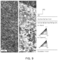
- FIG. 9 is a photograph of an image quality (IQ) and an inverse pole figure (IPF) of Comparative Example 1 observed with EBSD
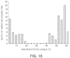
- FIG. 10 is a graph of a ratio of a grain boundary according to a misorientation angle between grains of Comparative Example 1.
- FIG. 11 is a photograph of an image quality (IQ) and an inverse pole figure (IPF) of Comparative Example 2 observed with EBSD
- FIG. 12 is a graph of a ratio of a grain boundary according to a misorientation angle between grains of Comparative Example 2.
Landscapes
- Engineering & Computer Science (AREA)
- Mechanical Engineering (AREA)
- Chemical & Material Sciences (AREA)
- Materials Engineering (AREA)
- Metallurgy (AREA)
- Organic Chemistry (AREA)
- Physics & Mathematics (AREA)
- Plasma & Fusion (AREA)
- Arc Welding In General (AREA)
Abstract
Description
- The present disclosure relates to a gas-shielded arc welding wire, a welding member having excellent fatigue resistance characteristics and resistance to deformation due to residual stress in a weld zone, and a method for manufacturing the same.
- In the automotive field, research into light-weight technology for car bodies and parts is emerging as a major issue due to fuel economy regulation policies for environmental protection, such as to mitigate the effects of global warming. Chassis parts, which are important for vehicle driving performance, also require the application of high-strength steel for weight reduction in accordance with this principle. In order to achieve weight reduction of parts, it is essential to increase the strength of the material, and it is an important factor to guarantee durability of parts formed of high-strength steel in an environment in which repeated fatigue loads are applied. In the case of arc welding, which is mainly used to secure strength when assembling automobile chassis parts, since overlap joint welding is performed between parts by welding of a welding wire, it is unavoidable to provide a geometric shape of a joint portion. This acts as a repetitive fatigue stress concentration portion (notch effect) and becomes a fracture point, resulting in a decrease in the durability of the part, so that there is a limitation in which an advantage of applying high-strength steel is lost. It has been reported that, mainly reducing an angle (toe angle) of an end portion of a bead, which is a main stress concentration portion, is most important factor in the fatigue characteristics of the weld zone, and has no direct correlation with softening of a heat affected zone (HAZ) due to heat input from welding.
- According to Patent Document 1, in order to improve fatigue characteristics of an arc weld zone manufactured using a steel having a plate thickness of 5 mm or less and tensile strength of 780 MPa or more, a concept of material control for each position of a temperature section of a weld bead toe portion, that is, the heat affected zone (HAZ) (For example, the position of minimum hardness at a depth of 0.1 mm from a surface thereof must be at least 0.3 mm away from a melting line), was proposed, but there is a limitation that Patent Document 1 fails to disclose a technology to improve the strength of welding metal and control stress characteristics of the weld zone through the improvement of properties of a welding material.
- In
Patent Document 2, it is suggested that the fatigue characteristics may be improved by applying a compressive stress by continuously hitting an end portion of a weld bead with a chipper (beating pin) to form a plastic deformation region. In Patent Document 3, in order to reduce a toe angle of arc weld bead between a sub-frame and a bracket, which are chassis parts for automobiles, a re-melting treatment method of the end portion of the weld bead through a plasma heat source after welding was proposed. However, the proposed methods have a problem in that a process cost increases when manufacturing parts because a post-welding process is added. - Meanwhile, in general, in the case of a thin steel sheet having tensile strength of 950 MPa or more, deformation due to tensile residual stress occurs after arc welding for manufacturing chassis parts, which not only deteriorates assembly properties, but also reduces the fatigue characteristics of a weld zone due to the tensile residual stress of the weld zone.
-
- (Patent Document 1)
Japanese Patent Laid-Open No. 2013-220431 - (Patent Document 2)
Japanese Patent Laid-Open No. 2014-014831 - (Patent Document 3)
Japanese Patent Laid-Open No. 2014-004609 - An aspect of the present disclosure is to provide a gas shielded arc welding wire capable of imparting excellent fatigue resistance characteristics and resistance to deformation due to residual stress to a weld zone.
- Another aspect of the present disclosure is to provide a welding member having excellent fatigue resistance characteristics and resistance to deformation due to residual stress of a weld zone, and a method for manufacturing the same.
- According to an aspect of the present disclosure, a gas-shielded arc welding wire having excellent fatigue resistance characteristics and resistance to deformation due to residual stress in a weld zone is provided, the gas-shielded arc welding wire including, by weight %, 0.06 to 0.16% of C, 0.001 to 0.2% of Si, 1.6 to 1.9% of Mn, 1.2 to 6.0% of Cr, 0.4 to 0.65% of Mo, 0.015% or less (excluding 0%) of P, 0.01% or less (excluding 0%) of S, 0.20% or less (excluding 0%) of Al, and a remainder of Fe and other unavoidable impurities, wherein a value in Equation 1 below is 300 to 500,
732 - 202×C + 216×Si - 85×Mn - 37×Ni - 47×Cr - 39×Mo - According to another aspect of the present disclosure, a welding member including a base material and a weld zone is provided, the welding member having excellent fatigue resistance characteristics and resistance to deformation due to residual stress in a weld zone, wherein the weld zone includes, by weight%, 0.05 to 0.16% of C, 0.001 to 1.0 of Si, 1.4 to 2.5% of Mn, 0.4 to 5.0% of Cr, 0.1 to 1.5% of Mo, 0.015% or less (excluding 0%)of P, 0.01% or less(excluding 0%) of S, 0.20% or less (excluding 0%)of Al, and a remainder of Fe and other unavoidable impurities, wherein the weld zone has a microstructure including bainite; acicular ferrite; and at least one of granular ferrite, martensite and retained austenite; wherein the microstructure has an average effective grain size of 10 µm or less, and a ratio of high-hardness grain boundaries with a misorientation angle between grain boundaries of 55° or more respective to total grain boundaries is 40% or more, and a value of R expressed by
Equation 2 below is 10.5 to 18.5,

- According to another aspect of the present disclosure, a method for manufacturing a welding member is provided, wherein the method for manufacturing a welding member is obtained by preparing two or more base materials, and then gas-shielded arc welding using a welding wire, the method for manufacturing a welding member having excellent fatigue resistance characteristics and resistance to deformation due to residual stress of a weld zone, wherein the welding wire includes, by weight %, 0.06 to 0.16% of C, 0.001 to 0.2% of Si, 1.6 to 1.9% of Mn, 1.2 to 6.0% of Cr, 0.4 to 0.65% of Mo, 0.015% or less (excluding 0%) of P, 0.01% or less (excluding 0%)of S, 0.20% or less (excluding 0%) of Al, and a remainder of Fe and other unavoidable impurities, wherein a value of Equation 1 below is 300 to 500, wherein, during the gas-shielded arc welding, a value of Equation 4 below is 1.2 to 1.6,
732 - 202×C + 216×Si - 85×Mn - 37×Ni - 47×Cr - 39×Mo 
- According to an aspect of the present disclosure, a gas-shielded arc welding wire capable of imparting excellent fatigue resistance characteristics and resistance to deformation due to residual stress to a weld zone may be provided.
- According to another aspect of the present disclosure, a welding member having excellent fatigue resistance characteristics and resistance to deformation due to residual stress in a weld zone, and a method for manufacturing the same, may be provided.
-
-
FIG. 1 is an image quality (IQ) and inverse pole figure (IPF) photograph of Inventive Example 1 according to an embodiment of the present disclosure observed with EBSD. -
FIG. 2 is a graph of a ratio of a grain boundary according to a misorientation angle between grains of Inventive Example 1 according to an embodiment of the present disclosure. -
FIG. 3 is an image quality (IQ) and inverse pole figure (IPF) photograph of Inventive Example 2 according to an embodiment of the present disclosure observed with EBSD. -
FIG. 4 is a graph of a ratio of a grain boundary according to a misorientation angle between grains of Inventive Example 2 according to an embodiment of the present disclosure. -
FIG. 5 is an image quality (IQ) and inverse pole figure (IPF) photograph of Inventive Example 3 according to an embodiment of the present disclosure observed with EBSD. -
FIG. 6 is a graph of a ratio of a grain boundary according to a misorientation angle between grains of Inventive Example 3 according to an embodiment of the present disclosure. -
FIG. 7 is an image quality (IQ) and inverse pole figure (IPF) photograph of Inventive Example 4 according to an embodiment of the present disclosure observed with EBSD. -
FIG. 8 is a graph of a ratio of a grain boundary according to a misorientation angle between grains of Inventive Example 4 according to an embodiment of the present disclosure. -
FIG. 9 is an image quality (IQ) and inverse pole figure (IPF) photograph of Inventive Example 4 according to an embodiment of the present disclosure observed with EBSD. -
FIG. 10 is a graph of a ratio of a grain boundary according to a misorientation angle between grains of Comparative Example 1 according to an embodiment of the present disclosure. -
FIG. 11 is an image quality (IQ) and inverse pole figure (IPF) photograph of Comparative Example 2 according to an embodiment of the present disclosure observed with EBSD. -
FIG. 12 is a graph of a ratio of a grain boundary according to a misorientation angle between grains of Comparative Example 2 according to an embodiment of the present disclosure. - Hereinafter, a gas-shielded arc welding wire according to an embodiment of the present disclosure will be described. A content of an alloy composition described below is in wt%.
- Carbon (C) is beneficial for an action of stabilizing arc to atomize a volume, and is also a beneficial element for securing hardenability. When a content of C is less than 0.06%, the volume becomes coarse and the arc becomes unstable, and an amount of spatter generation increases, and it may be difficult to secure sufficient strength of a welding metal, which may be disadvantageous. On the other hand, when the content of C exceeds 0.16%, there may be a disadvantage in that viscosity of molten metal is lowered, resulting in a poor bead shape, as well as excessive hardening of the welding metal, thereby reducing toughness. A lower limit of the content of C is more preferably 0.062%, is even more preferably 0.065%, and is most preferably 0.07%. An upper limit of the content of C is more preferably 0.12%, is even more preferably 0.10%, and is most preferably 0.09%.
- Silicon (Si) is an element (a deoxidation element) promoting deoxidation of molten metal during arc welding, and is effective in suppressing the occurrence of blowholes. When a content of Si is less than 0.001%, there may be a disadvantage in that deoxidation becomes insufficient and blowholes are likely to be generated, and when the content of Si exceeds 0.2%, there may be a disadvantage in that non-conductive slag is generated excessively, paint defects in a weld zone are caused and penetrability of molten metal is lowered due to a lack of surface activation of the welded portion due to excessive deoxidation. A lower limit of the content of Si is more preferably 0.01%, is even more preferably 0.02%, and is most preferably 0.04%. An upper limit of the content of Si is more preferably 0.15%, is even more preferably 0.10%, and is most preferably 0.08%.
- Manganese (Mn) is a deoxidizing element and is an element for promoting deoxidation of molten metal during arc welding and suppressing generation of blowholes. When a content of Mn is less than 1.6%, there may be a disadvantage in that deoxidation becomes insufficient and blowholes are likely to be generated. When the content of Mn exceeds 1.9%, there may be a disadvantage in that viscosity of molten metal becomes excessively high, and when a welding speed is high, the molten metal cannot properly flow into a welded site, resulting in a humped bead, which is likely to cause a poor bead shape. A lower limit of the content of Mn is more preferably 1.65%, is even more preferably 1.7%, and is most preferably 1.75%. An upper limit of the content of Mn is more preferably 1.87%, is even more preferably 1.85%, and is most preferably 1.8%.
- Cr is a ferrite stabilizing element, and is an element advantageous for securing hardenability to improve strength of welding metal. When a content of Cr is less than 1.2%, there may be a disadvantage in that it is difficult to secure sufficient strength of the welding metal, and when the content of Cr exceeds 6.0%, there may be a disadvantage in that brittleness of the welding metal is unnecessarily increased in some cases, making it difficult to sufficient toughness. A lower limit of the content of Cr is more preferably 1.25%, is even more preferably 1.30%, and is most preferably 1.35%. An upper limit of the content of Cr is more preferably 5.8%, is even more preferably 5.5%, and is most preferably 5.2%.
- Molybdenum (Mo) is a ferrite stabilizing element, and is an element advantageous for securing hardenability to improve strength of welding metal. When a content of Mo is less than 0.4%, there may be a disadvantage in that it is difficult to secure sufficient strength of welding metal, and when the content of Mo exceeds 0.65%, there may be a disadvantage in that toughness of the welding metal is lowered in some cases. A lower limit of the content of Mo is more preferably 0.42%, is even more preferably 0.44%, and is most preferably 0.46%. An upper limit of the content of Mo is more preferably 0.62%, is even more preferably 0.60%, and is most preferably 0.58%.
- Phosphorus (P) is an element that is generally incorporated as an unavoidable impurity in steel, and is also an element included as a normal impurity in a solid wire for arc welding. When a content of P exceeds 0.015%, there may be a disadvantage in that high-temperature cracking of welding metal becomes remarkable. The content of P is more preferably 0.014% or less, is even more preferably 0.012% or less, and is most preferably 0.01% or less.
- Sulfur (S) is also generally incorporated as an unavoidable impurity in steel, and is also an element included as a normal impurity in a solid wire for arc welding. When a content of S exceeds 0.01%, toughness of welding metal deteriorates in some cases, and surface tension of molten metal is insufficient during welding, so that there may be a disadvantage in which a molten portion flows downwardly excessively due to gravity during high-speed vertical welding, resulting in a poor shape of the weld bead. The content of S is more preferably 0.008% or less, is even more preferably 0.006% or less, and is most preferably 0.005% or less.
- Aluminum (Al) is a deoxidizing element and is an element capable of promoting deoxidation of molten metal during arc welding and improving strength of welding metal even in a small amount. When a content of Al exceeds 0.20%, generation of Al-based oxides increase, so that there may be a disadvantage in that strength and toughness of the welding metal are deteriorated in some cases, and electrodeposition paint defects of a weld zone become sensitive due to non-conductive oxides. The content of Al is more preferably 0.15% or less, is even more preferably 0.12% or less, and is most preferably 0.10% or less.
- A remainder of the present disclosure may be iron (Fe). However, in a general manufacturing process, inevitable impurities may be added from raw materials or an ambient environment, and thus, impurities may not be excluded. A person skilled in the art of a general manufacturing process may be aware of the impurities, and thus, the descriptions of the impurities may not be provided in the present disclosure.
- In addition to the alloy composition described above, the wire of the present disclosure may further include at least one of 0.40% or less of Ni and 0.50% or less of Cu.
- Nickel (Ni) is an element capable of improving strength and toughness of welding metal. However, when a content of Ni exceeds 0.40%, there may be a disadvantage in that it becomes sensitive to cracks. The content of Ni is more preferably 0.30% or less, is even more preferably 0.20% or less, and is most preferably 0.10% or less.
- Copper (Cu) is generally contained in about 0.02% as an impurity in steel constituting a wire, and in a solid wire for arc welding, a content of Cu may be determined mainly due to copper plating performed on a surface of the wire. Cu is an element capable of stabilizing feedability and conductivity of the wire. However, when the content of Cu exceeds 0.50%, there may be a disadvantage in that crack susceptibility of the welding metal is increased. The content of Cu is more preferably 0.45% or less, is even more preferably 0.40% or less, and is most preferably 0.30% or less.
- Meanwhile, the wire of the present disclosure preferably satisfies the alloy composition described above, and a value of Equation 1 below is preferably 300 to 500. The Equation 1 below is to form a microstructure of a welding metal portion to be a dense structure in which acicular ferrite and bainite are interlocked in a complex form by utilizing transformation of lower bainite including acicular ferrite, and to offset contractile tensile stress generated during solidification of a melting pool using compressive residual stress in the weld zone generated by transformation expansion through lowering a low-temperature transformation initiation temperature, or to add additional compressive stress. When a value of the following Equation 1 is less than 300, hardenability may be excessively increased and a low-temperature transformation structure is excessively developed so that there may be a disadvantage in that toughness of welding metal is insufficient and the low-temperature transformation initiation temperature is too low so that a fraction of retained austenite increases and an effect of decreasing transformation expansion simultaneously. On the other hand, when the value of the following Equation 1 is less than 300, conversely, an effect of lower bainite transformation including acicular ferrite described above may not be sufficiently obtained, so that there may be a disadvantage in that the microstructure of the welding metal may not be formed to be dense and the low-temperature transformation initiation temperature rises, resulting in significantly reducing the effect of offsetting the tensile residual stress of the weld zone as well. A lower limit of the value of the following Equation 1 is more preferably 312, is even more preferably 315, and is most preferably 318. An upper limit of the value of the following Equation 1 is more preferably 498, is even more preferably 496, and is most preferably 494.
732 - 202×C + 216×Si - 85×Mn - 37×Ni - 47×Cr - 39×Mo - In the present disclosure, a shape or type of a wire is not particularly limited, but, for example, the wire of the present disclosure may be one of a solid wire, a metal-cored wire, and a flux-cored wire.
- Hereinafter, a welding member according to an embodiment of the present disclosure will be described. The welding member of the present disclosure includes a base material and a weld zone. Hereinafter, an alloy composition of the weld zone will be described first. A content of the alloy composition described below is in wt%. A lower limit of the content of Mn is more preferably 1.45%, is even more preferably 1.50%, and is most preferably 1.55%. An upper limit of the content of Mn is more preferably 2.47%, is even more preferably 2.45%, and is most preferably 2.43%.
- Carbon (C) is a major element capable of lowering a temperature at which transformation of acicular ferrite, bainite, and martensite is initiated through diffusionless transformation according to continuous cooling in a high-temperature austenite phase in a solidification process of welding metal. When a content of C is less than 0.05%, hardenability decreases, making it difficult to secure sufficient strength of the welding metal, and according to the above-described principle, the low-temperature transformation initiation temperature is not sufficiently lowered, so there may be a disadvantage in that an effect of offsetting tensile residual stress of the weld zone due to the a low-temperature transformation expansion effect during a cooling process is significantly reduced, and a grain boundary structure having a high-hardness angle having a misorientation angle between grains is not formed. On the other hand, when a content of C exceeds 0.16%, viscosity of molten metal is lowered, resulting in a poor bead shape, as well as excessive hardening of the welding metal to reduce toughness. Here, the low-temperature transformation temperature may be excessively low so that compressive stress due to low-temperature transformation may not be secured at a temperature near room temperature and a retained austenite phase, an untransformed phase may increase in a final welding metal structure. A lower limit of the content of C is more preferably 0.052%, is even more preferably 0.055%, and is most preferably 0.58%. An upper limit of the content of C is more preferably 0.12%, is even more preferably 0.1%, and is most preferably 0.09%.
- Silicon (Si) is an element (a deoxidation element) promoting deoxidation of molten metal during arc welding, and is effective in suppressing the occurrence of blowholes and increasing a low-temperature transformation initiation temperature. When a content of Si is less than 0.001%, there may be a disadvantage in that deoxidation becomes insufficient and blowholes is likely to be generated, and the low-temperature transformation initiation temperature may be excessively lowered, thereby reducing an effect of offsetting tensile residual stress of the weld zone. On the other hand, when the content of Si exceeds 1.0%, there may be a disadvantage in that non-conductive slag is generated excessively, paint defects in a weld zone are caused, and penetrability of molten metal is lowered due to a lack of surface activation of the weld zone due to excessive deoxidation and the low-temperature transformation initiation temperature may increase so that a sufficient compressive stress effect due to low-temperature transformation is not be obtained. A lower limit of the content of Si is more preferably 0.01%, is even more preferably 0.02%, and is most preferably 0.04%. An upper limit of the content of Si is more preferably 0.85%, is even more preferably 0.75%, and is most preferably 0.65%.
- Manganese (Mn) is a deoxidizing element and is an element of promoting deoxidation of molten metal during arc welding to suppress occurrence of blowholes, and is an element of reducing a low-temperature transformation initiation temperature such as C. When a content of Mn is less than 1.4%, deoxidation becomes insufficient and blowholes are likely to be generated and a low-temperature transformation initiation temperature is increased so that there may be a disadvantage in that it is not possible to obtain a sufficient compressive stress effect according to low-temperature transformation. On the other hand, when the content of Mn exceeds 2.5%, viscosity of welding metal becomes excessively high, and a welding speed thereof is high, molten metal cannot properly flow into a welded site, so that there may be a disadvantage in that a poor bead shape is likely to be generated as a humped bead is formed, and the low-temperature transformation initiation temperature is too low so that an effect of offsetting tensile residual stress in the weld zone decreases. A lower limit of the content of Mn is more preferably 1.45%, is even more preferably 1.50%, and is most preferably 1.55%. An upper limit of the content of Si is more preferably 2.47%, is even more preferably 2.45%, and is most preferably 2.43%.
- Chromium (Cr) is a ferrite stabilizing element, and an element for lowering a low-temperature transformation initiation temperature, and is an element advantageous for improving strength by securing hardenability of the welding metal. When a content of Cr is less than 0.4%, a ratio of high-hardness grain boundaries is reduced and it may be difficult to sufficiently obtain a compressive stress effect, and it may be difficult to secure sufficient strength in welding metal. On the other hand, when the content of Cr exceeds 5.0%, brittleness of the welding metal is unnecessarily increased in some cases, so that it may be difficult to secure sufficient toughness, and the low-temperature transformation initiation temperature may be too low, so that the compressive stress of the weld zone may not be sufficiently secured. A lower limit of the content of Cr is more preferably 0.44%, is even more preferably 0.47%, and is most preferably 0.50%. An upper limit of the content of Cr is more preferably 4.8%, is even more preferably 4.5%, and is most preferably 4.2%.
- Molybdenum (Mo) is a ferrite stabilizing element, and is an element lowering a low-temperature initiation temperature, and is an element, advantageous for improving strength of welding metal according to securing hardenability of the welding metal. When a content of Mo is less than 0.1%, a ratio of high-hardness grain boundaries of welding metal is reduced and it is difficult to sufficiently obtain a compressive stress effect according to low-temperature transformation and it may be difficult to secure sufficient strength of the welding metal. On the other hand, when the content of Mo exceeds 1.5%, toughness of the welding metal is lowered in some cases, and the low-temperature transformation initiation temperature may be too low, so that the compressive stress of the weld zone may not be sufficiently secured. A lower limit of the content of Mo is more preferably 0.16%, is even more preferably 0.18%, and is most preferably 0.2%. An upper limit of the content of Mo is more preferably 1.48%, is even more preferably 1.46%, and is most preferably 1.44%.
- Phosphorus (P) is an element that is generally incorporated as an unavoidable impurity in steel. When a content of P exceeds 0.015%, there may be a disadvantage in that high-temperature cracking of welding metal becomes remarkable. The content of P is more preferably 0.014% or less, is even more preferably 0.012% or less, and is most preferably 0.01% or less.
- Sulfur (S) is also generally incorporated as an unavoidable impurity in steel. When a content of S exceeds 0.01%, toughness of welding metal deteriorates in some cases, and surface tension of molten metal is insufficient during welding, so that there may be a disadvantage in which a molten portion flows downwardly excessively due to gravity during high-speed vertical welding (welding from top to bottom during vertical welding), resulting in a poor shape of the weld bead. The content of S is more preferably 0.008% or less, is even more preferably 0.006% or less, and is most preferably 0.005% or less.
- Aluminum (Al) is a deoxidizing element and is an element capable of promoting deoxidation of molten metal during arc welding and improving strength of welding metal even in a small amount. When a content of Al exceeds 0.20%, generation of Al-based oxides increase, there may be a disadvantage in that strength and toughness of the welding metal are deteriorated in some cases, and electrodeposition paint defects of a weld zone become sensitive due to non-conductive oxides. The content of Al is more preferably 0.15% or less, is even more preferably 0.12% or less, and is most preferably 0.10% or less.
- A remainder of the present disclosure may be iron (Fe). However, in a general manufacturing process, inevitable impurities may be added from raw materials or an ambient environment, and thus, impurities may not be excluded. A person skilled in the art of a general manufacturing process will be aware of such impurities, and thus, the descriptions of the impurities may not be provided in the present disclosure.
- In addition to the alloy composition described above, the welding member of the present disclosure may further include at least one of 0.40% or less of Ni and 0.50% or less of Cu.
- Nickel (Ni) is an element capable of improving strength and toughness of welding metal. However, when a content of Ni exceeds 0.40%, there may be a disadvantage in that it becomes sensitive to cracks. The content of Ni is more preferably 0.30% or less, is even more preferably 0.20% or less, and is most preferably 0.10% or less.
- Copper (Cu) is an effective element for improving strength of welding metal. However, when a content of Cu exceeds 0.50%, there may be a disadvantage in that crack susceptibility of the welding metal is increased. The content of Cu is more preferably 0.45% or less, is even more preferably 0.40% or less, and is most preferably 0.30% or less. Meanwhile, in order to sufficiently obtain an effect of improving strength, Cu may be contained in the welding metal in an amount of 0.01% or more.
- Meanwhile, it is preferable that the weld zone of the welding member of the present disclosure includes a microstructure including bainite; acicular ferrite; and at least one of granular ferrite, martensite and retained austenite. In the present disclosure, in particular, by appropriately controlling a value of Equation 1 as described above, a microstructure of a welding metal portion is formed as a structure in which acicular ferrite and bainite are interlocked in complex form, that is a structure in which a misorientation angle between grains has a high-hardness angle, by utilizing lower bainite transformation including acicular ferrite within od austenite grains that occurs during a cooling process after welding, and by lowering a low-temperature transformation initiation temperature, it is possible to obtain an effect of offsetting contractile tensile stress generated during solidification during melting or adding additional compressive stress with compressive residual stress of a weld zone that occurs through low-temperature transformation expansion.
- In this case, the microstructure of the weld zone preferably has an average effective grain size of 10 µm or less. As described above, by finely controlling the average effective grain size, it is possible to obtain an effect of securing relatively excellent strength and toughness of welding metal. When the average effective grain size exceeds 10 um, it is difficult to simultaneously secure sufficient strength and toughness of welding metal as described above. The average effective grain size is more preferably 7 µm or less, even more preferably 5 µm or less, and most preferably 4 µm or less. Meanwhile, the average effective grain size may be defined as an average size of grains converted from the number of grains per unit area.
- In addition, in the microstructure of the weld zone, it is preferable that a ratio of a hard-hardness grain boundary in which a misorientation angle between grains is 55° or more relative to the total grain boundaries is 40% or more. By controlling the ratio of high-hardness grain boundaries as described above, sufficient strength and toughness of the welding metal may be simultaneously secured through formation of a very dense and complex microstructure, and, in particular, a low-temperature transformation expansion effect that can sufficiently offset tensile residual stress of a weld zone of a thin steel sheet having tensile strength of 950 MPa or higher may be obtained. However, when a ratio of the high-hardness grain boundary is less than 40%, there is a disadvantage in that the above-described characteristics are insufficient. The ratio of the high-hardness grain boundary is more preferably 44% or more, even more preferably 47% or more, and most preferably 50% or more.
- In addition, it is preferable that the weld zone has a value of R of 10.5 to 18.5 expressed by the following
Equation 2.Equation 2 below is to increase a misorientation angle between grains realized according to the effect of Equation 1 above, and effective grains constituting the same are fine-grained to form a more dense and complex microstructure. When the value ofEquation 2 below is less than 10.5, there may be a disadvantage in that the strength and toughness of welding metal may not be sufficiently secured, and when the value thereof exceeds 18.5, brittleness of the welding metal becomes too high so that there may be a disadvantage of being sensitive to cracking. A lower limit of the value of the followingEquation 2 is preferably 10.6, even more preferably 10.8, and most preferably 11. An upper limit of the value of the followingEquation 2 is preferably 18.4, even more preferably 18.2, and most preferably 18. Meanwhile, in theEquation 2 below, a misorientation angle between grains may consider a series of lattice arrangement constituting grains as one grain and in this case, the angle may be defined as an angle formed by each grain boundary.

- A weld zone of the present disclosure provided as described above may have fatigue strength of 140 MPa or more. In addition, the weld zone may have compressive residual stress of 90 MPa or more in a region within 5 mm in a direction perpendicular to the base material from an end portion of a weld bead. Meanwhile, the types of the residual stress may include tensile residual stress and compressive residual stress, and in the case of tensile residual stress, in particular, a problem of deterioration of fatigue resistance characteristics of the weld zone may occur. Accordingly, in the present disclosure, an appropriate level of compressive residual stress is applied to the weld zone. As described above, the welding member of the present disclosure may have excellent fatigue resistance characteristics and resistance to deformation due to residual stress of the weld zone, so that it is possible to effectively improve durability and assemblability of a product when applied to automobile parts.
- Meanwhile, in the present disclosure, an alloy composition of the base material is not particularly limited. However, as an example, the base material may include, by wt%, 0.05 to 0.13% of C, 0.2 to 2.0% of Si, 1.3 to 3.0% of Mn, 0.01 to 2.0% of Cr, 0.01 to 2.0% of Mo, 0.01 to 0.1% of Al, 0.001 to 0.05% of P, 0.001 to 0.05% of S, and a remainder of Fe and other unavoidable impurities. In addition, the base material may further include at least one of 0.01 to 0.2% of Ti and 0.01 to 0.1% of Nb. In addition, the base material may have a thickness of 0.8 to 4.0mm.
- In addition, in the present disclosure, there is no particular limitation on a method for manufacturing a welding member. However, one of the advantageous methods for manufacturing the welding member of the present disclosure will be described as follows.
- First, after preparing two or more base materials, in manufacturing a welding member by gas-shielded arc welding using a welding wire, the welding wire preferably satisfies the above-described alloy composition and a value of Equation 1. In addition, the base material may also have the above-described alloy composition. In addition, during the gas shielded arc welding, a value of the following Equation 4 is preferably 1.2 to 1.6. When the value of Equation 4 below is less than 1.2, hardenability of welding metal and a coarse grained heat affected zone is excessively increased, so that there may be a disadvantage that strength and toughness are insufficient, and when the value thereof exceeds 1.6, there may be disadvantages in that not only insufficient strength of welding metal and a decrease in strength of the welding heat-affected zone become too excessive, but also back bead and melting easily occur in the weld zone, resulting in defects. A lower limit of a value of the following Equation 4 is more preferably 1.24, even more preferably 1.26, and most preferably 1.28. An upper limit of a value of the following Equation 1 is more preferably 1.58, even more preferably 1.56, and most preferably 1.54.

- Hereinafter, the present disclosure will be described in detail through Examples. However, the following Examples are only examples for explaining the present disclosure in more detail, and do not limit the scope of the present disclosure.
- After preparing two steel sheets having a tensile strength of 980 MPa having an alloy composition disclosed in Table 1 below, and a thickness disclosed in Table 4 below, a welding member having a weld zone having an alloy composition illustrated in Table 3 below was manufactured performing gas-shielded welding while imparting a welding heat input disclosed in the Table 4 below using a solid wire having an alloy composition disclosed in Table 2 below. After measuring a microstructure, fatigue strength, and residual stress of the welded portion manufactured as described above, results thereof are illustrated in Tables 4 to 6 below.
- After taking a specimen from a weld zone, a microstructure was observed with an optical microscope by micro-polishing a cross-sectional structure of the specimen and then etching the same with a nital solution. In addition, Kikuchi patterns were analyzed through electron backscattered diffraction (EBSD), so that image quality (IQ) and inverse pole figure (IPF) maps were obtained, visualizing grain boundaries and grain orientation information. Thereafter, the average effective grain size was measured by classifying grain by referring the IQ and IPF map of EBSD along with a microstructure photograph observed with the optical microscope described above, and then calculating an average size of grains converted from the number of grains per unit area.
- A ratio of high-hardness grain boundaries having a misorientation angle between grains of 55° or more relative to the total grain boundaries in the weld zone was considered as one grain, and the angle formed by each grain boundary is regarded as one grain through the EBSD analysis method described above. In this case, after measuring the angle formed by each grain boundary, it was measured by extracting the ratio of grain boundaries having a misorientation angle of 55° or more among the total distribution of misorientation angles between grains.
- After taking a specimen from the welded portion of the welding member, fatigue strength was defined as a maximum load satisfying a fatigue life of 2 × 10⁶ Cycles by performing a fatigue test. The fatigue test measured the fatigue life (Cycles) using a tensile-tensile high-cycle fatigue test for each load, wherein a ratio of a minimum load and a maximum load was 0,1, a repetitive load frequency was 15 Hz. In addition, the fatigue life corresponding to strength (MPa), converted by dividing a load (kN) by an area according to a width and thickness of each specimen, was derived. In this case, the minimum load refers to a minimum value of a repetitive load having the above-described constant load applied frequency, and the maximum load refers to a maximum value of the repetitive load.
- Residual stress was calculated by measuring a change in an amount of stress added by measuring a change in a distance between lattices constituting grains using an X-ray diffraction principle for a region within 5 mm from an end portion of weld bead in the direction perpendicular to the base material. In this case, X-rays were generated from a Cr tube at a voltage of 30 kV and a current of 6.7 mA. Meanwhile, when a value of residual stress was negative (-), it was determined to be compressive residual stress, and when a value of residual stress was positive (+), it was determined to be tensile residual stress. In addition, a bead start portion refers to a weld bead formed by starting welding, a bead end portion means a weld bead formed by finishing welding, and a bead center portion means a weld bead located in a middle of the bead start portion and the bead end portion.
[Table 1] Base mater ial No. Alloy composition (by weight$) C Si Mn Cr Mo Al P S Ni Cu Remai nder 1 0.070 1.100 2.10 0.90 0.01 0.025 0.009 0.001 0.02 0.02 Fe 2 0.090 0.900 2.00 0.20 0.20 0.025 0.009 0.001 0.01 0.02 Fe [Table 2] Wire No. Alloy composition (by weight%) C Si Mn Cr Mo Al P S Ni Cu Rema inde r Equa tion 1 1 0.16 0.04 1.70 4.80 0.50 0.00 4 0.006 0.001 0.04 0.14 Fe 317 2 0.08 0.09 1.74 4.92 0.49 0.00 8 0.004 0.003 - 0.30 Fe 337 3 0.07 0.06 1.77 1.35 0.55 0.00 9 0.005 0.004 - 0.34 Fe 495 4 0.07 0.37 1.65 0.50 0.30 0.00 6 0.011 0.006 3.00 0.25 Fe 511 5 0.08 0.08 1.70 0.04 0.00 7 0.01 0 0.012 0.005 0.023 0.19 Fe 585 6 0.27 0.04 1.70 4.80 0.50 0.00 4 0.006 0.001 0.04 0.14 Fe 295 [Equation 1] 732 - 202×C + 216×Si - 85×Mn - 37×Ni - 47×Cr - 39×Mo [Table 3] Welding member No. Base mate rial No. Wire No. Alloy composition (by weight%) C Si Mn Cr Mo Al P S Ni Cu Rema inde r Inventi ve Example 1 1 1 0.10 0.56 1.87 2.60 0.22 0.01 3 0.00 8 0.001 3 0.03 8 0 . 0 Fe Inventi ve Example 2 1 2 0.08 0.51 1.82 2.43 0.21 0.01 7 0.01 1 0.001 5 0.00 9 0.16 Fe Inventi ve Example 3 2 2 0.08 0.62 1.90 1.30 0.24 0.01 4 0.01 3 0.002 2 0.00 7 0.17 Fe Inventi ve 2 3 0.08 0.59 1.90 0.50 0.26 0.01 1 0.01 1 0.002 8 0.00 6 0.18 Fe Example 4 Compara tive Example 1 2 4 0.08 0.63 1.80 0.32 0.21 0.00 8 0.01 5 0.004 1 1.3 0.14 Fe Compara tive Example 2 2 5 0.08 0.52 1.80 0.13 0.06 0.01 0 0.01 3 0.003 1 0.01 4 0.11 Fe Compara tive Example 3 1 6 0.17 0.56 1.87 2.60 0.22 0.01 3 0.00 8 0.001 3 0.03 8 0.08 Fe [Table 4] Welding member No. Thickne ss of base materia l (T) (mm) Heat input (Q) (kJ/c m) Microstr ucture Ratio of high-hardness grain boundary having a misorientation angle of 55° or more between grains compared to total grain boundaries (K) (%) Average effective grain size (G) (µm) R Inventi ve Example 3.5 5.2 AF+B+ M 40 3.3 18.1 1 Inventi ve Example 2 2.0 2.6 AF+B 53 6.2 11.2 Inventi ve Example 3 2.9 3.8 AF+ B 50 5.6 11.6 Inventi ve Example 4 2.9 3.9 AF+PF+ B 40 4.8 11.2 Compara tive Example 1 2.9 3.7 AF+PF+B 39 4.8 10.3 Compara tive Example 2 2.9 3.9 AF+PF 39 6.6 8.0 Compara tive Example 3 2.0 3.4 B+M+RA 37 8.4 7.5 AF: Acicular ferrite, PF: Polygonal ferrite, B: Bainite, M: Martensite, RA: Retained austenite R = (K / G) × (Q / T) Q = (I × E) × 0.048 / u(I: Welding current(A), E: Welding voltage(V), u: Welding speed(cm/min)) [Table 5] No • Maxi mum load (MPa ) Mini mum load (MPa ) Fatigue life (Cycles) Inventiv e Example 1 Inventiv e Example2 Inventiv e Examples Inventiv e Exaple4 Comparat ive Example1 Comparat ive Example2 Comparati ve Examples 1 240 24 98,430 118,790 102,638 Not measured Not measured Not measured Not measured 2 220 22 123,528 155,943 137,269 72,109 Not measured Not measured Not measured 3 200 20 213,637 241,957 226,372 131,479 Not measured Not measured Not measured 4 180 18 357,832 473,419 382,836 169,252 107,392 84,738 147,392 5 170 17 824,365 2,000,00 0 2,000,00 0 231,985 162,498 126,647 212,637 6 160 16 2,000,00 0 2,000,00 0 2,000,00 0 294,719 217,603 158,603 276,423 7 140 14 2,000,00 0 2,000,00 0 2,000,00 0 2,000,00 0 327,626 252,512 537,246 8 120 12 2,000,00 0 2,000,00 0 2,000,00 0 2,000,00 0 694,714 361,843 2,000,000 9 110 11 2,000,00 0 2,000,00 0 2,000,00 0 2,000,00 0 2,000,00 0 853,274 2,000,000 10 100 10 2,000,00 0 2,000,00 0 2,000,00 0 2,000,00 0 2,000,00 0 2,000,00 0 2,000,000 [Table 6] Welding member No. Measurement point Residual stress (MPa) 1.0mm 2.0mm 3.0mm 4.0mm 5.0mm Inventive Example1 Bead start portion -362.4 -309.4 -274.9 -270.5 -370.5 Bead center portion -254.7 -198.6 -247.6 -195.6 -284.3 Bead end portion -424.8 -362.9 -460.6 -522.3 -492.3 Inventive Example2 Bead start portion -170.6 -231.0 -174.1 -207.4 -264.2 Bead center portion -147.9 -221.6 -141.9 -139.2 -102.3 Bead end portion -110.2 -147.0 -167.9 -130.3 -114.6 Inventive Example3 Bead start portion -196.3 -280.7 -260.3 -363.5 -402.9 Bead center portion -389.1 -247.6 -359.4 -316.8 -295.7 Bead end portion -424.3 -409.2 -519.9 -506.5 -435.1 Inventive Example 4 Bead start portion -121.3 -178.6 -157.5 -159.0 -194.9 Bead center portion -93.0 -129.9 -182.4 -134.0 -103.4 Bead end portion -239.4 -215.2 -186.7 -181.8 -217.8 Comparati ve Example1 Bead start portion 285.1 144.6 194.3 218.2 153.2 Bead center portion 184.2 122.8 170.4 129.8 100.6 Bead end portion 218.2 228.1 229.2 202.9 196.4 Comparati ve Example2 Bead start portion 338.3 354.6 318.2 295.4 175.6 Bead center portion 243.3 220.5 225.4 274.6 216.8 Bead end portion 221.4 284.6 251.6 135.7 110.6 Comparati ve Example3 Bead start portion -75.2 -87.6 -67.3 -56.7 -83.5 Bead center portion -56.7 -43.8 -62.9 -53.4 -73.6 Bead end portion -84.6 -72.4 -87.2 -86.3 -73.4 -
FIG. 1 is a photograph of an image quality (IQ) and an inverse pole figure (IPF) of Inventive Example 1 observed with EBSD, andFIG. 2 is a graph of a ratio of a grain boundary according to a misorientation angle between grains of Inventive Example 1. -
FIG. 3 is a photograph of an image quality (IQ) and an inverse pole figure (IPF) of Inventive Example 2 observed with EBSD, andFIG. 4 is a graph of a ratio of a grain boundary according to a misorientation angle between grains of Inventive Example 2. -
FIG. 5 is a photograph of an image quality (IQ) and an inverse pole figure (IPF) of Inventive Example 3 observed with EBSD, andFIG. 6 is a graph of a ratio of a grain boundary according to a misorientation angle between grains of Inventive Example 3. -
FIG. 7 is a photograph of an image quality (IQ) and an inverse pole figure (IPF) of Inventive Example 4 observed with EBSD, andFIG. 8 is a graph of a ratio of a grain boundary according to a misorientation angle between grains of Inventive Example 4. -
FIG. 9 is a photograph of an image quality (IQ) and an inverse pole figure (IPF) of Comparative Example 1 observed with EBSD, andFIG. 10 is a graph of a ratio of a grain boundary according to a misorientation angle between grains of Comparative Example 1. -
FIG. 11 is a photograph of an image quality (IQ) and an inverse pole figure (IPF) of Comparative Example 2 observed with EBSD, andFIG. 12 is a graph of a ratio of a grain boundary according to a misorientation angle between grains of Comparative Example 2. - As can be seen from Tables 1 to 6 and
FIGS. 1 to 12 , in the case of Inventive Examples 1 to 4, it can be seen that excellent fatigue strength and compressive residual stress are secured as the conditions suggested by the present disclosure are satisfied. On the other hand, in the case of Comparative Examples 1 to 3, since the conditions suggested by the present disclosure are not satisfied, it can be seen that not only the fatigue strength is low, but also the tensile residual stress exists or compressive strength is at a low level. - While example embodiments have been shown and described above, it will be apparent to those skilled in the art that modifications and variations could be made without departing from the scope of the present disclosure as defined by the appended claims.
Claims (14)
- A gas-shielded arc welding wire having excellent fatigue resistance characteristics and resistance to deformation due to residual stress in a weld zone, comprising, by weight %,0.06 to 0.16% of C, 0.001 to 0.2% of Si, 1.6 to 1.9% of Mn, 1.2 to 6.0% of Cr, 0.4 to 0.65% of Mo, 0.015% or less (excluding 0%) of P, 0.01% or less (excluding 0%) of S, 0.20% or less (excluding 0%) of Al, and a remainder of Fe and other unavoidable impurities,wherein a value in Equation 1 below is 300 to 500,
732 - 202×C + 216×Si - 85×Mn - 37×Ni - 47×Cr - 39×Mo where, a content of each element in [Equation 1] is in wt%. - The gas-shielded arc welding wire having excellent fatigue resistance characteristics and resistance to deformation due to residual stress in a weld zone of claim 1,
wherein the wire further comprises at least one of 0.40% or less of Ni and 0.50% or less of Cu. - The gas-shielded arc welding wire having excellent fatigue resistance characteristics and resistance to deformation due to residual stress in a weld zone of claim 1,
wherein the wire is one of a solid wire, a metal-cored wire and flux-cored wire. - As a welding member including a base material and a weld zone, the welding member having excellent fatigue resistance characteristics and resistance to deformation due to residual stress in a weld zone,wherein the weld zone comprises, by weight%,0.05 to 0.16% of C, 0.001 to 1.0 of Si, 1.4 to 2.5% of Mn, 0.4 to 5.0% of Cr, 0.1 to 1.5% of Mo, 0.015% or less (excluding 0%)of P, 0.01% or less (excluding 0%)of S, 0.20% or less (excluding 0%)of Al, and a remainder of Fe and other inevitable impurities,wherein the weld zone has a microstructure including bainite; acicular ferrite; and at least one of granular ferrite, martensite and retained austenite;wherein the microstructure has an average effective grain size of 10 µm or less, and a ratio of high-hardness grain boundaries with a misorientation angle between grain boundaries of 55° or more respective to the total grain boundaries is 40% or more, anda value of R expressed by the following Equation 2 is 10.5 to 18.5,
 where, in [Equation 2], K is a ratio of grain boundaries with a misorientation angle of 55° or more relative to total grain boundaries in a weld zone (%), G is an average effective grain size of the weld zone (µm), T is a thickness of a base material (mm), and Q is a welding heat input (kJ/cm), where Q is defined by the following [Equation 3]
 where, in [Equation 3], I is a welding current (A), E is a welding voltage (V), and u is a welding speed (cm/min).
 - The welding member having excellent fatigue resistance characteristics and resistance to deformation due to residual stress in a weld zone of claim 4, wherein the weld zone further comprises at least one of 0.40% or less of Ni and 0.50% or less of Cu.
- The welding member having excellent fatigue resistance characteristics and resistance to deformation due to residual stress in a weld zone of claim 4, wherein the weld zone has fatigue strength of 140 MPa or more.
- The welding member having excellent fatigue resistance characteristics and resistance to deformation due to residual stress in a weld zone of claim 4, wherein the weld zone has compressive residual stress of 90 MPa or more in a region within 5 mm from an end portion of a weld bead in a direction, perpendicular to a base material.
- The welding member having excellent fatigue resistance characteristics and resistance to deformation due to residual stress in a weld zone of claim 4, wherein the base material comprises, by weight%,
0.05 to 0.13% of C, 0.2 to 2.0% of Si, 1.3 to 3.0% of Mn, 0.01 to 2.0% of Cr, 0.01 to 2.0% of Mo, 0.01 to 0.1% of Al, 0.001 to 0.05% of P, 0.001 to 0.05% of S, and a remainder of Fe and other inevitable impurities. - The welding member having excellent fatigue resistance characteristics and resistance to deformation due to residual stress of a weld zone of claim 8, wherein the base material further comprises at least one of 0.01 to 0.2% of Ti and 0.01 to 0.1% of Nb.
- The welding member having excellent fatigue resistance and resistance to deformation due to residual stress of a weld zone of claim 4, wherein the base material has a thickness of 0.8 to 4.0 mm.
- As a method for manufacturing a welding member obtained by preparing two or more base materials, and then gas-shielded arc welding using a welding wire, the method for manufacturing a welding member having excellent fatigue resistance characteristics and resistance to deformation due to residual stress of a weld zone,wherein the welding wire comprises, by weight %,0.06 to 0.16% of C, 0.001 to 0.2% of Si, 1.6 to 1.9% of Mn, 1.2 to 6.0% of Cr, 0.4 to 0.65% of Mo, 0.015% or less (excluding 0%)of P, 0.01% or less (excluding 0%)of S, 0.20% or less(excluding 0%)of Al, and a remainder of Fe and other unavoidable impurities, wherein a value of Equation 1 below is 300 to 500,wherein, during the gas-shielded arc welding, a value of Equation 4 below is 1.2 to 1.6,
732 - 202×C + 216×Si - 85×Mn - 37×Ni - 47×Cr - 39×Mo where, in [Equation 1], a content of each element is in wt% where, in [Equation 4], T is a thickness of a base material (mm) and Q is a welding heat input (kJ/cm), where Q is defined by the following [Equation 3]
 where, in [Equation 3], I is a welding current (A), E is a welding voltage (V), and u is a welding speed (cm/min).
 - The method for manufacturing a welding member having excellent fatigue resistance characteristics and resistance to deformation due to residual stress in a weld zone of claim 11,
wherein the base material comprises, by wt%, 0.05 to 0.13% of C, 0.2 to 2.0% of Si, 1.3 to 3.0% of Mn, 0.01 to 2.0% of Cr, 0.01 to 2.0% of Mo, 0.01 to 0.1% of Al, 0.001 to 0.05% of P, 0.001 to 0.05% of S, and a remainder of Fe and other unavoidable impurities. - The method for manufacturing a welding member having excellent fatigue resistance characteristics and resistance to deformation due to residual stress of a weld zone of claim 12,
wherein the base material further comprises at least one of 0.01 to 0.2% of Ti and 0.01 to 0.1% of Nb. - The method for manufacturing a welding member having excellent fatigue resistance characteristics and resistance to deformation due to residual stress in a weld zone of claim 11, wherein the base material has a thickness of 0.8 to 4.0 mm.
Applications Claiming Priority (2)
| Application Number | Priority Date | Filing Date | Title |
|---|---|---|---|
| KR1020210123734A KR102788860B1 (en) | 2021-09-16 | 2021-09-16 | Wire for gas-shielded arc welding and welded member having excellent fatigue resistance properties and resistance to deformation due to residual stress of weld zone and method of manufacturing the same |
| PCT/KR2021/019365 WO2023042974A1 (en) | 2021-09-16 | 2021-12-20 | Wire and welding member for gas-shielded arc welding having excellent fatigue resistance characteristics and resistance against deformation due to residual stress of welding zone, and manufacturing method therefor |
Publications (2)
| Publication Number | Publication Date |
|---|---|
| EP4403295A1 true EP4403295A1 (en) | 2024-07-24 |
| EP4403295A4 EP4403295A4 (en) | 2025-06-11 |
Family
ID=85603026
Family Applications (1)
| Application Number | Title | Priority Date | Filing Date |
|---|---|---|---|
| EP21957640.2A Pending EP4403295A4 (en) | 2021-09-16 | 2021-12-20 | Wire and welding member for gas-shielded arc welding having excellent fatigue resistance characteristics and resistance against deformation due to residual stress of welding zone, and manufacturing method therefor |
Country Status (7)
| Country | Link |
|---|---|
| US (1) | US12617045B2 (en) |
| EP (1) | EP4403295A4 (en) |
| JP (1) | JP7505006B2 (en) |
| KR (1) | KR102788860B1 (en) |
| CN (1) | CN116829297B (en) |
| MX (1) | MX2023004766A (en) |
| WO (1) | WO2023042974A1 (en) |
Families Citing this family (1)
| Publication number | Priority date | Publication date | Assignee | Title |
|---|---|---|---|---|
| CN119598722B (en) * | 2024-11-18 | 2025-08-01 | 华中科技大学 | Method and system for predicting three-dimensional solidification crack sensitivity of aluminum alloy laser welding seam |
Family Cites Families (29)
| Publication number | Priority date | Publication date | Assignee | Title |
|---|---|---|---|---|
| WO1995024292A1 (en) | 1994-03-11 | 1995-09-14 | Nippon Steel Corporation | Wire for gas metal-arc welding |
| JP2892288B2 (en) * | 1994-10-05 | 1999-05-17 | 日本鋼管工事株式会社 | Rail welding method by gas shielded arc welding method |
| JP3283773B2 (en) * | 1996-10-31 | 2002-05-20 | 株式会社神戸製鋼所 | High strength Cr-Mo steel coated arc welding metal and coated arc welding method |
| CA2231985C (en) | 1997-03-26 | 2004-05-25 | Sumitomo Metal Industries, Ltd. | Welded high-strength steel structures and methods of manufacturing the same |
| JP4461587B2 (en) | 2000-08-07 | 2010-05-12 | Jfeスチール株式会社 | Gas shield arc welding method for thin steel sheet |
| US20040140303A1 (en) | 2002-01-31 | 2004-07-22 | Tokihiko Kataoka | Steel wire for carbon dioxide shielded arc welding and welding process using the same |
| JP3867000B2 (en) | 2002-03-27 | 2007-01-10 | 株式会社神戸製鋼所 | Solid wire for gas shielded arc welding and its original wire |
| JP3900086B2 (en) | 2003-01-29 | 2007-04-04 | 住友金属工業株式会社 | Welding materials and weld metals |
| JP4441372B2 (en) | 2004-10-13 | 2010-03-31 | 新日本製鐵株式会社 | High strength and high toughness gas shielded arc welding wire |
| JP4614226B2 (en) | 2005-04-07 | 2011-01-19 | 株式会社神戸製鋼所 | Solid wire for gas shielded arc welding |
| EP1767659A1 (en) | 2005-09-21 | 2007-03-28 | ARCELOR France | Method of manufacturing multi phase microstructured steel piece |
| JP4853575B2 (en) * | 2009-02-06 | 2012-01-11 | Jfeスチール株式会社 | High strength steel pipe for low temperature excellent in buckling resistance and weld heat affected zone toughness and method for producing the same |
| KR101704839B1 (en) * | 2009-06-24 | 2017-02-08 | 신닛테츠스미킹 마테리알즈 가부시키가이샤 | Copper alloy bonding wire for semiconductor |
| WO2011155620A1 (en) | 2010-06-07 | 2011-12-15 | 新日本製鐵株式会社 | Ultra high-strength welded joint and method for producing same |
| JP5909143B2 (en) | 2012-04-13 | 2016-04-26 | 株式会社神戸製鋼所 | MAG welding method for hot rolled steel sheet and MIG welding method for hot rolled steel sheet |
| JP5985901B2 (en) | 2012-06-25 | 2016-09-06 | Jfeスチール株式会社 | Welded joint and method for forming the same |
| JP2014014831A (en) | 2012-07-09 | 2014-01-30 | Jfe Steel Corp | Fatigue strength improving method of weld zone and welded joint |
| CN103659016B (en) * | 2012-09-06 | 2016-06-01 | 日本铸锻钢株式会社 | The manufacture method of the collar of 9��12%Cr steel turbine rotor and the collar manufactured by the method |
| CA2964729C (en) | 2014-11-19 | 2020-03-10 | Nippon Steel Corporation | Laser welded joint, vehicle component, manufacturing method of laser welded joint, and manufacturing method of vehicle component |
| EP3246426B1 (en) * | 2015-01-16 | 2020-06-24 | JFE Steel Corporation | Method for manufacturing a thick high-toughness high-strength steel sheet |
| CN105880871A (en) * | 2016-05-26 | 2016-08-24 | 武汉铁锚焊接材料股份有限公司 | Gas-shielded high-toughness solid welding wire and use method and application thereof |
| JP2018187640A (en) | 2017-05-01 | 2018-11-29 | 株式会社神戸製鋼所 | Arc welding method and welding wire |
| JP6810019B2 (en) | 2017-12-15 | 2021-01-06 | 株式会社神戸製鋼所 | Gas shielded arc welding wire and gas shielded arc welding method |
| CN110948136A (en) | 2018-09-27 | 2020-04-03 | 宝山钢铁股份有限公司 | Ultralow-carbon gas shielded welding wire suitable for ultralow heat input automatic welding and manufacturing method thereof |
| CN109093286A (en) * | 2018-09-29 | 2018-12-28 | 四川西冶新材料股份有限公司 | A kind of 2.25Cr-1Mo steel exchange submerged arc welding welding wire and solder flux |
| CN113302315B (en) | 2019-01-09 | 2023-06-30 | 日本制铁株式会社 | Hot-rolled steel sheet, welded joint, and method for producing same |
| JP7277742B2 (en) | 2019-06-26 | 2023-05-19 | 日本製鉄株式会社 | solid wire |
| JP7510049B2 (en) | 2019-06-26 | 2024-07-03 | 日本製鉄株式会社 | Solid wire for gas shielded arc welding and method for manufacturing welded joint |
| JP6969705B1 (en) | 2019-12-20 | 2021-11-24 | Jfeスチール株式会社 | Steel wire for gas shielded arc welding, gas shielded arc welding method, and manufacturing method of gas shielded arc welded joint |
-
2021
- 2021-09-16 KR KR1020210123734A patent/KR102788860B1/en active Active
- 2021-12-20 CN CN202180073600.9A patent/CN116829297B/en active Active
- 2021-12-20 US US18/031,821 patent/US12617045B2/en active Active
- 2021-12-20 WO PCT/KR2021/019365 patent/WO2023042974A1/en not_active Ceased
- 2021-12-20 MX MX2023004766A patent/MX2023004766A/en unknown
- 2021-12-20 JP JP2022543498A patent/JP7505006B2/en active Active
- 2021-12-20 EP EP21957640.2A patent/EP4403295A4/en active Pending
Also Published As
| Publication number | Publication date |
|---|---|
| JP2023545225A (en) | 2023-10-27 |
| KR20230040512A (en) | 2023-03-23 |
| JP7505006B2 (en) | 2024-06-24 |
| CN116829297B (en) | 2026-01-02 |
| CN116829297A (en) | 2023-09-29 |
| KR102788860B1 (en) | 2025-03-31 |
| EP4403295A4 (en) | 2025-06-11 |
| US20230390873A1 (en) | 2023-12-07 |
| US12617045B2 (en) | 2026-05-05 |
| MX2023004766A (en) | 2023-05-09 |
| WO2023042974A1 (en) | 2023-03-23 |
Similar Documents
| Publication | Publication Date | Title |
|---|---|---|
| KR102210135B1 (en) | High-strength plated steel sheet for welded structural member and method for manufacturing said sheet | |
| EP3473740B1 (en) | Automobile member having resistance weld | |
| KR20200124740A (en) | High strength galvanized steel sheet, high strength member and their manufacturing method | |
| KR101643271B1 (en) | Abrasion resistant welded steel pipe and method of producing the same | |
| US10081073B2 (en) | Spot welded joint | |
| KR102589430B1 (en) | Resistance spot welds and resistance spot welding methods, and resistance spot welding joints and manufacturing methods of resistance spot welding joints | |
| KR20120138226A (en) | High-strength steel sheet excellent in workability and cold brittleness resistance, and manufacturing method thereof | |
| JP5505572B2 (en) | High strength hot rolled steel sheet and method for producing the same | |
| KR20210107821A (en) | High-strength steel sheet and its manufacturing method | |
| WO2019077777A1 (en) | High-strength steel sheet and manufacturing method thereof | |
| KR102210100B1 (en) | High-strength plated steel sheet and its manufacturing method | |
| KR20190028488A (en) | High strength steel sheet and manufacturing method thereof | |
| CN115087511B (en) | Weldment with excellent weld fatigue strength and method of manufacturing the same | |
| KR102398709B1 (en) | High-strength steel sheet and its manufacturing method | |
| TW201522663A (en) | High-strength hot-rolled steel sheet and method for manufacturing same | |
| US12617045B2 (en) | Gas-shielded arc welding wire and welding member having excellent fatigue resistance characteristics and resistance to deformation due to residual stress in weld zone, and method for manufacturing same | |
| JPH08144008A (en) | High-strength steel and manufacturing method thereof | |
| JP4513311B2 (en) | Welded joint with excellent fatigue strength characteristics | |
| KR102964149B1 (en) | Resistance spot welded joint and the resistance spot welding method | |
| EP4545243A1 (en) | Welding member, and wire for gas-shielded arc welding | |
| JP7727221B2 (en) | Arc weld metal, welded joints, and automotive components | |
| JP7755218B2 (en) | Steel plates and parts | |
| KR20260047615A (en) | Steel plate, resistance spot welding method, resistance spot welded member, and method of manufacturing steel plate | |
| CN119630828A (en) | High-strength steel plate and method for producing the same, and component and method for producing the same |
Legal Events
| Date | Code | Title | Description |
|---|---|---|---|
| STAA | Information on the status of an ep patent application or granted ep patent |
Free format text: STATUS: THE INTERNATIONAL PUBLICATION HAS BEEN MADE |
|
| PUAI | Public reference made under article 153(3) epc to a published international application that has entered the european phase |
Free format text: ORIGINAL CODE: 0009012 |
|
| STAA | Information on the status of an ep patent application or granted ep patent |
Free format text: STATUS: REQUEST FOR EXAMINATION WAS MADE |
|
| 17P | Request for examination filed |
Effective date: 20230413 |
|
| AK | Designated contracting states |
Kind code of ref document: A1 Designated state(s): AL AT BE BG CH CY CZ DE DK EE ES FI FR GB GR HR HU IE IS IT LI LT LU LV MC MK MT NL NO PL PT RO RS SE SI SK SM TR |
|
| DAV | Request for validation of the european patent (deleted) | ||
| DAX | Request for extension of the european patent (deleted) | ||
| A4 | Supplementary search report drawn up and despatched |
Effective date: 20250514 |
|
| RIC1 | Information provided on ipc code assigned before grant |
Ipc: B23K 9/173 20060101ALI20250508BHEP Ipc: C22C 38/50 20060101ALI20250508BHEP Ipc: C22C 38/48 20060101ALI20250508BHEP Ipc: C22C 38/58 20060101ALI20250508BHEP Ipc: C22C 38/44 20060101ALI20250508BHEP Ipc: C22C 38/38 20060101ALI20250508BHEP Ipc: C22C 38/22 20060101ALI20250508BHEP Ipc: C22C 38/20 20060101ALI20250508BHEP Ipc: C22C 38/06 20060101ALI20250508BHEP Ipc: C22C 38/02 20060101ALI20250508BHEP Ipc: B23K 35/02 20060101ALI20250508BHEP Ipc: B23K 35/30 20060101AFI20250508BHEP |
|
| GRAP | Despatch of communication of intention to grant a patent |
Free format text: ORIGINAL CODE: EPIDOSNIGR1 |
|
| STAA | Information on the status of an ep patent application or granted ep patent |
Free format text: STATUS: GRANT OF PATENT IS INTENDED |
|
| INTG | Intention to grant announced |
Effective date: 20260105 |
|
| GRAJ | Information related to disapproval of communication of intention to grant by the applicant or resumption of examination proceedings by the epo deleted |
Free format text: ORIGINAL CODE: EPIDOSDIGR1 |
|
| STAA | Information on the status of an ep patent application or granted ep patent |
Free format text: STATUS: REQUEST FOR EXAMINATION WAS MADE |
|
| INTC | Intention to grant announced (deleted) | ||
| GRAP | Despatch of communication of intention to grant a patent |
Free format text: ORIGINAL CODE: EPIDOSNIGR1 |
|
| STAA | Information on the status of an ep patent application or granted ep patent |
Free format text: STATUS: GRANT OF PATENT IS INTENDED |
|
| GRAJ | Information related to disapproval of communication of intention to grant by the applicant or resumption of examination proceedings by the epo deleted |
Free format text: ORIGINAL CODE: EPIDOSDIGR1 |
|
| STAA | Information on the status of an ep patent application or granted ep patent |
Free format text: STATUS: REQUEST FOR EXAMINATION WAS MADE |
|
| INTG | Intention to grant announced |
Effective date: 20260331 |
|
| GRAP | Despatch of communication of intention to grant a patent |
Free format text: ORIGINAL CODE: EPIDOSNIGR1 |
|
| STAA | Information on the status of an ep patent application or granted ep patent |
Free format text: STATUS: GRANT OF PATENT IS INTENDED |