EP4403248A1 - Verfahren zur erzeugung von erneuerbarem erdgas - Google Patents
Verfahren zur erzeugung von erneuerbarem erdgas Download PDFInfo
- Publication number
- EP4403248A1 EP4403248A1 EP23160215.2A EP23160215A EP4403248A1 EP 4403248 A1 EP4403248 A1 EP 4403248A1 EP 23160215 A EP23160215 A EP 23160215A EP 4403248 A1 EP4403248 A1 EP 4403248A1
- Authority
- EP
- European Patent Office
- Prior art keywords
- stream
- carbon dioxide
- gas
- absorption
- unit
- Prior art date
- Legal status (The legal status is an assumption and is not a legal conclusion. Google has not performed a legal analysis and makes no representation as to the accuracy of the status listed.)
- Pending
Links
- VNWKTOKETHGBQD-UHFFFAOYSA-N methane Chemical compound C VNWKTOKETHGBQD-UHFFFAOYSA-N 0.000 title claims abstract description 127
- 238000000034 method Methods 0.000 title claims abstract description 88
- 239000003345 natural gas Substances 0.000 title abstract description 25
- CURLTUGMZLYLDI-UHFFFAOYSA-N Carbon dioxide Chemical compound O=C=O CURLTUGMZLYLDI-UHFFFAOYSA-N 0.000 claims abstract description 223
- 229910002092 carbon dioxide Inorganic materials 0.000 claims abstract description 128
- 238000010521 absorption reaction Methods 0.000 claims abstract description 104
- 239000001569 carbon dioxide Substances 0.000 claims abstract description 94
- 239000012528 membrane Substances 0.000 claims abstract description 91
- 230000008569 process Effects 0.000 claims abstract description 62
- 238000000926 separation method Methods 0.000 claims abstract description 48
- XLYOFNOQVPJJNP-UHFFFAOYSA-N water Substances O XLYOFNOQVPJJNP-UHFFFAOYSA-N 0.000 claims abstract description 41
- VUZPPFZMUPKLLV-UHFFFAOYSA-N methane;hydrate Chemical compound C.O VUZPPFZMUPKLLV-UHFFFAOYSA-N 0.000 claims abstract description 4
- 239000007789 gas Substances 0.000 claims description 103
- 238000011069 regeneration method Methods 0.000 claims description 56
- 230000008929 regeneration Effects 0.000 claims description 53
- 239000002250 absorbent Substances 0.000 claims description 50
- 230000002745 absorbent Effects 0.000 claims description 50
- 239000012466 permeate Substances 0.000 claims description 34
- 239000000047 product Substances 0.000 claims description 28
- 238000001179 sorption measurement Methods 0.000 claims description 25
- 239000012465 retentate Substances 0.000 claims description 20
- QVGXLLKOCUKJST-UHFFFAOYSA-N atomic oxygen Chemical compound [O] QVGXLLKOCUKJST-UHFFFAOYSA-N 0.000 claims description 19
- 239000001301 oxygen Substances 0.000 claims description 19
- 229910052760 oxygen Inorganic materials 0.000 claims description 19
- 230000009467 reduction Effects 0.000 claims description 15
- 239000000356 contaminant Substances 0.000 claims description 14
- 238000000746 purification Methods 0.000 claims description 14
- 150000002430 hydrocarbons Chemical class 0.000 claims description 11
- QGZKDVFQNNGYKY-UHFFFAOYSA-N Ammonia Chemical compound N QGZKDVFQNNGYKY-UHFFFAOYSA-N 0.000 claims description 10
- 229930195733 hydrocarbon Natural products 0.000 claims description 10
- 238000011084 recovery Methods 0.000 claims description 6
- -1 siloxanes Chemical class 0.000 claims description 6
- 229910021529 ammonia Inorganic materials 0.000 claims description 5
- 238000001816 cooling Methods 0.000 claims description 5
- 239000007857 degradation product Substances 0.000 claims description 5
- 230000009286 beneficial effect Effects 0.000 claims 1
- 238000005265 energy consumption Methods 0.000 abstract description 14
- 239000007788 liquid Substances 0.000 description 60
- 150000001412 amines Chemical class 0.000 description 26
- 239000012535 impurity Substances 0.000 description 19
- 239000002904 solvent Substances 0.000 description 19
- GLUUGHFHXGJENI-UHFFFAOYSA-N Piperazine Chemical compound C1CNCCN1 GLUUGHFHXGJENI-UHFFFAOYSA-N 0.000 description 18
- 239000002253 acid Substances 0.000 description 16
- LYCAIKOWRPUZTN-UHFFFAOYSA-N Ethylene glycol Chemical compound OCCO LYCAIKOWRPUZTN-UHFFFAOYSA-N 0.000 description 14
- 230000006835 compression Effects 0.000 description 11
- 238000007906 compression Methods 0.000 description 11
- 239000006096 absorbing agent Substances 0.000 description 10
- 238000011068 loading method Methods 0.000 description 9
- HZAXFHJVJLSVMW-UHFFFAOYSA-N 2-Aminoethan-1-ol Chemical compound NCCO HZAXFHJVJLSVMW-UHFFFAOYSA-N 0.000 description 7
- OKTJSMMVPCPJKN-UHFFFAOYSA-N Carbon Chemical group [C] OKTJSMMVPCPJKN-UHFFFAOYSA-N 0.000 description 7
- 230000018044 dehydration Effects 0.000 description 7
- 238000006297 dehydration reaction Methods 0.000 description 7
- WGCNASOHLSPBMP-UHFFFAOYSA-N hydroxyacetaldehyde Natural products OCC=O WGCNASOHLSPBMP-UHFFFAOYSA-N 0.000 description 7
- 238000004519 manufacturing process Methods 0.000 description 6
- 238000012545 processing Methods 0.000 description 6
- RWSOTUBLDIXVET-UHFFFAOYSA-N Dihydrogen sulfide Chemical compound S RWSOTUBLDIXVET-UHFFFAOYSA-N 0.000 description 5
- 239000003463 adsorbent Substances 0.000 description 5
- 238000006731 degradation reaction Methods 0.000 description 5
- 229910000037 hydrogen sulfide Inorganic materials 0.000 description 5
- 239000000243 solution Substances 0.000 description 5
- 238000012546 transfer Methods 0.000 description 5
- PVXVWWANJIWJOO-UHFFFAOYSA-N 1-(1,3-benzodioxol-5-yl)-N-ethylpropan-2-amine Chemical compound CCNC(C)CC1=CC=C2OCOC2=C1 PVXVWWANJIWJOO-UHFFFAOYSA-N 0.000 description 4
- IJGRMHOSHXDMSA-UHFFFAOYSA-N Atomic nitrogen Chemical compound N#N IJGRMHOSHXDMSA-UHFFFAOYSA-N 0.000 description 4
- QMMZSJPSPRTHGB-UHFFFAOYSA-N MDEA Natural products CC(C)CCCCC=CCC=CC(O)=O QMMZSJPSPRTHGB-UHFFFAOYSA-N 0.000 description 4
- VYPSYNLAJGMNEJ-UHFFFAOYSA-N Silicium dioxide Chemical compound O=[Si]=O VYPSYNLAJGMNEJ-UHFFFAOYSA-N 0.000 description 4
- 230000015556 catabolic process Effects 0.000 description 4
- 238000005516 engineering process Methods 0.000 description 4
- 239000002808 molecular sieve Substances 0.000 description 4
- URGAHOPLAPQHLN-UHFFFAOYSA-N sodium aluminosilicate Chemical compound [Na+].[Al+3].[O-][Si]([O-])=O.[O-][Si]([O-])=O URGAHOPLAPQHLN-UHFFFAOYSA-N 0.000 description 4
- 238000010977 unit operation Methods 0.000 description 4
- 241000196324 Embryophyta Species 0.000 description 3
- 230000003750 conditioning effect Effects 0.000 description 3
- 239000003546 flue gas Substances 0.000 description 3
- UGFAIRIUMAVXCW-UHFFFAOYSA-N Carbon monoxide Chemical compound [O+]#[C-] UGFAIRIUMAVXCW-UHFFFAOYSA-N 0.000 description 2
- 230000015572 biosynthetic process Effects 0.000 description 2
- 238000006243 chemical reaction Methods 0.000 description 2
- 125000004122 cyclic group Chemical group 0.000 description 2
- 230000001747 exhibiting effect Effects 0.000 description 2
- 230000001788 irregular Effects 0.000 description 2
- 230000007246 mechanism Effects 0.000 description 2
- 239000000203 mixture Substances 0.000 description 2
- 229910052757 nitrogen Inorganic materials 0.000 description 2
- 239000007800 oxidant agent Substances 0.000 description 2
- 238000012856 packing Methods 0.000 description 2
- 150000003141 primary amines Chemical class 0.000 description 2
- 230000009919 sequestration Effects 0.000 description 2
- 239000000741 silica gel Substances 0.000 description 2
- 229910002027 silica gel Inorganic materials 0.000 description 2
- 239000011877 solvent mixture Substances 0.000 description 2
- 239000000126 substance Substances 0.000 description 2
- 230000000153 supplemental effect Effects 0.000 description 2
- 239000012855 volatile organic compound Substances 0.000 description 2
- 239000010457 zeolite Substances 0.000 description 2
- 241000894006 Bacteria Species 0.000 description 1
- KXDHJXZQYSOELW-UHFFFAOYSA-M Carbamate Chemical compound NC([O-])=O KXDHJXZQYSOELW-UHFFFAOYSA-M 0.000 description 1
- 229910021536 Zeolite Inorganic materials 0.000 description 1
- 230000002378 acidificating effect Effects 0.000 description 1
- 230000000274 adsorptive effect Effects 0.000 description 1
- PNEYBMLMFCGWSK-UHFFFAOYSA-N aluminium oxide Inorganic materials [O-2].[O-2].[O-2].[Al+3].[Al+3] PNEYBMLMFCGWSK-UHFFFAOYSA-N 0.000 description 1
- 238000013459 approach Methods 0.000 description 1
- 239000007864 aqueous solution Substances 0.000 description 1
- 229910052799 carbon Inorganic materials 0.000 description 1
- 238000007084 catalytic combustion reaction Methods 0.000 description 1
- 238000002144 chemical decomposition reaction Methods 0.000 description 1
- 238000003889 chemical engineering Methods 0.000 description 1
- 238000002485 combustion reaction Methods 0.000 description 1
- 238000009833 condensation Methods 0.000 description 1
- 230000005494 condensation Effects 0.000 description 1
- 230000001143 conditioned effect Effects 0.000 description 1
- 238000010276 construction Methods 0.000 description 1
- 238000005260 corrosion Methods 0.000 description 1
- 230000007797 corrosion Effects 0.000 description 1
- 230000003247 decreasing effect Effects 0.000 description 1
- 238000003795 desorption Methods 0.000 description 1
- HNPSIPDUKPIQMN-UHFFFAOYSA-N dioxosilane;oxo(oxoalumanyloxy)alumane Chemical compound O=[Si]=O.O=[Al]O[Al]=O HNPSIPDUKPIQMN-UHFFFAOYSA-N 0.000 description 1
- 238000009826 distribution Methods 0.000 description 1
- 238000001704 evaporation Methods 0.000 description 1
- 230000008020 evaporation Effects 0.000 description 1
- 239000000284 extract Substances 0.000 description 1
- 230000002349 favourable effect Effects 0.000 description 1
- 210000003608 fece Anatomy 0.000 description 1
- 239000003337 fertilizer Substances 0.000 description 1
- 239000012530 fluid Substances 0.000 description 1
- 238000005187 foaming Methods 0.000 description 1
- 239000000446 fuel Substances 0.000 description 1
- 239000000499 gel Substances 0.000 description 1
- 238000010438 heat treatment Methods 0.000 description 1
- 230000006872 improvement Effects 0.000 description 1
- 239000011261 inert gas Substances 0.000 description 1
- 239000003112 inhibitor Substances 0.000 description 1
- 238000002347 injection Methods 0.000 description 1
- 239000007924 injection Substances 0.000 description 1
- 239000010871 livestock manure Substances 0.000 description 1
- CRVGTESFCCXCTH-UHFFFAOYSA-N methyl diethanolamine Chemical compound OCCN(C)CCO CRVGTESFCCXCTH-UHFFFAOYSA-N 0.000 description 1
- 239000002754 natural gas substitute Substances 0.000 description 1
- 238000005457 optimization Methods 0.000 description 1
- 239000011368 organic material Substances 0.000 description 1
- 239000005416 organic matter Substances 0.000 description 1
- 239000010815 organic waste Substances 0.000 description 1
- 238000011027 product recovery Methods 0.000 description 1
- 238000010926 purge Methods 0.000 description 1
- 239000012264 purified product Substances 0.000 description 1
- 230000009257 reactivity Effects 0.000 description 1
- 238000005057 refrigeration Methods 0.000 description 1
- 229920006395 saturated elastomer Polymers 0.000 description 1
- 239000010865 sewage Substances 0.000 description 1
- 239000000377 silicon dioxide Substances 0.000 description 1
- 239000007787 solid Substances 0.000 description 1
- 230000001629 suppression Effects 0.000 description 1
- 238000003786 synthesis reaction Methods 0.000 description 1
- ZIBGPFATKBEMQZ-UHFFFAOYSA-N triethylene glycol Chemical compound OCCOCCOCCO ZIBGPFATKBEMQZ-UHFFFAOYSA-N 0.000 description 1
- 238000011144 upstream manufacturing Methods 0.000 description 1
- 238000009834 vaporization Methods 0.000 description 1
- 230000008016 vaporization Effects 0.000 description 1
- 239000002699 waste material Substances 0.000 description 1
Images

Classifications
-
- B—PERFORMING OPERATIONS; TRANSPORTING
- B01—PHYSICAL OR CHEMICAL PROCESSES OR APPARATUS IN GENERAL
- B01D—SEPARATION
- B01D53/00—Separation of gases or vapours; Recovering vapours of volatile solvents from gases; Chemical or biological purification of waste gases, e.g. engine exhaust gases, smoke, fumes, flue gases, aerosols
- B01D53/14—Separation of gases or vapours; Recovering vapours of volatile solvents from gases; Chemical or biological purification of waste gases, e.g. engine exhaust gases, smoke, fumes, flue gases, aerosols by absorption
- B01D53/1406—Multiple stage absorption
-
- B—PERFORMING OPERATIONS; TRANSPORTING
- B01—PHYSICAL OR CHEMICAL PROCESSES OR APPARATUS IN GENERAL
- B01D—SEPARATION
- B01D53/00—Separation of gases or vapours; Recovering vapours of volatile solvents from gases; Chemical or biological purification of waste gases, e.g. engine exhaust gases, smoke, fumes, flue gases, aerosols
- B01D53/14—Separation of gases or vapours; Recovering vapours of volatile solvents from gases; Chemical or biological purification of waste gases, e.g. engine exhaust gases, smoke, fumes, flue gases, aerosols by absorption
- B01D53/1425—Regeneration of liquid absorbents
-
- B—PERFORMING OPERATIONS; TRANSPORTING
- B01—PHYSICAL OR CHEMICAL PROCESSES OR APPARATUS IN GENERAL
- B01D—SEPARATION
- B01D53/00—Separation of gases or vapours; Recovering vapours of volatile solvents from gases; Chemical or biological purification of waste gases, e.g. engine exhaust gases, smoke, fumes, flue gases, aerosols
- B01D53/14—Separation of gases or vapours; Recovering vapours of volatile solvents from gases; Chemical or biological purification of waste gases, e.g. engine exhaust gases, smoke, fumes, flue gases, aerosols by absorption
- B01D53/1431—Pretreatment by other processes
-
- B—PERFORMING OPERATIONS; TRANSPORTING
- B01—PHYSICAL OR CHEMICAL PROCESSES OR APPARATUS IN GENERAL
- B01D—SEPARATION
- B01D53/00—Separation of gases or vapours; Recovering vapours of volatile solvents from gases; Chemical or biological purification of waste gases, e.g. engine exhaust gases, smoke, fumes, flue gases, aerosols
- B01D53/14—Separation of gases or vapours; Recovering vapours of volatile solvents from gases; Chemical or biological purification of waste gases, e.g. engine exhaust gases, smoke, fumes, flue gases, aerosols by absorption
- B01D53/1456—Removing acid components
- B01D53/1462—Removing mixtures of hydrogen sulfide and carbon dioxide
-
- B—PERFORMING OPERATIONS; TRANSPORTING
- B01—PHYSICAL OR CHEMICAL PROCESSES OR APPARATUS IN GENERAL
- B01D—SEPARATION
- B01D53/00—Separation of gases or vapours; Recovering vapours of volatile solvents from gases; Chemical or biological purification of waste gases, e.g. engine exhaust gases, smoke, fumes, flue gases, aerosols
- B01D53/14—Separation of gases or vapours; Recovering vapours of volatile solvents from gases; Chemical or biological purification of waste gases, e.g. engine exhaust gases, smoke, fumes, flue gases, aerosols by absorption
- B01D53/1456—Removing acid components
- B01D53/1468—Removing hydrogen sulfide
-
- B—PERFORMING OPERATIONS; TRANSPORTING
- B01—PHYSICAL OR CHEMICAL PROCESSES OR APPARATUS IN GENERAL
- B01D—SEPARATION
- B01D53/00—Separation of gases or vapours; Recovering vapours of volatile solvents from gases; Chemical or biological purification of waste gases, e.g. engine exhaust gases, smoke, fumes, flue gases, aerosols
- B01D53/14—Separation of gases or vapours; Recovering vapours of volatile solvents from gases; Chemical or biological purification of waste gases, e.g. engine exhaust gases, smoke, fumes, flue gases, aerosols by absorption
- B01D53/1456—Removing acid components
- B01D53/1475—Removing carbon dioxide
-
- B—PERFORMING OPERATIONS; TRANSPORTING
- B01—PHYSICAL OR CHEMICAL PROCESSES OR APPARATUS IN GENERAL
- B01D—SEPARATION
- B01D53/00—Separation of gases or vapours; Recovering vapours of volatile solvents from gases; Chemical or biological purification of waste gases, e.g. engine exhaust gases, smoke, fumes, flue gases, aerosols
- B01D53/14—Separation of gases or vapours; Recovering vapours of volatile solvents from gases; Chemical or biological purification of waste gases, e.g. engine exhaust gases, smoke, fumes, flue gases, aerosols by absorption
- B01D53/1487—Removing organic compounds
-
- B—PERFORMING OPERATIONS; TRANSPORTING
- B01—PHYSICAL OR CHEMICAL PROCESSES OR APPARATUS IN GENERAL
- B01D—SEPARATION
- B01D53/00—Separation of gases or vapours; Recovering vapours of volatile solvents from gases; Chemical or biological purification of waste gases, e.g. engine exhaust gases, smoke, fumes, flue gases, aerosols
- B01D53/14—Separation of gases or vapours; Recovering vapours of volatile solvents from gases; Chemical or biological purification of waste gases, e.g. engine exhaust gases, smoke, fumes, flue gases, aerosols by absorption
- B01D53/18—Absorbing units; Liquid distributors therefor
-
- B—PERFORMING OPERATIONS; TRANSPORTING
- B01—PHYSICAL OR CHEMICAL PROCESSES OR APPARATUS IN GENERAL
- B01D—SEPARATION
- B01D53/00—Separation of gases or vapours; Recovering vapours of volatile solvents from gases; Chemical or biological purification of waste gases, e.g. engine exhaust gases, smoke, fumes, flue gases, aerosols
- B01D53/22—Separation of gases or vapours; Recovering vapours of volatile solvents from gases; Chemical or biological purification of waste gases, e.g. engine exhaust gases, smoke, fumes, flue gases, aerosols by diffusion
- B01D53/225—Multiple stage diffusion
- B01D53/226—Multiple stage diffusion in serial connexion
-
- B—PERFORMING OPERATIONS; TRANSPORTING
- B01—PHYSICAL OR CHEMICAL PROCESSES OR APPARATUS IN GENERAL
- B01D—SEPARATION
- B01D53/00—Separation of gases or vapours; Recovering vapours of volatile solvents from gases; Chemical or biological purification of waste gases, e.g. engine exhaust gases, smoke, fumes, flue gases, aerosols
- B01D53/22—Separation of gases or vapours; Recovering vapours of volatile solvents from gases; Chemical or biological purification of waste gases, e.g. engine exhaust gases, smoke, fumes, flue gases, aerosols by diffusion
- B01D53/229—Integrated processes (Diffusion and at least one other process, e.g. adsorption, absorption)
-
- B—PERFORMING OPERATIONS; TRANSPORTING
- B01—PHYSICAL OR CHEMICAL PROCESSES OR APPARATUS IN GENERAL
- B01D—SEPARATION
- B01D2252/00—Absorbents, i.e. solvents and liquid materials for gas absorption
- B01D2252/20—Organic absorbents
- B01D2252/204—Amines
- B01D2252/20405—Monoamines
-
- B—PERFORMING OPERATIONS; TRANSPORTING
- B01—PHYSICAL OR CHEMICAL PROCESSES OR APPARATUS IN GENERAL
- B01D—SEPARATION
- B01D2252/00—Absorbents, i.e. solvents and liquid materials for gas absorption
- B01D2252/20—Organic absorbents
- B01D2252/204—Amines
- B01D2252/20431—Tertiary amines
-
- B—PERFORMING OPERATIONS; TRANSPORTING
- B01—PHYSICAL OR CHEMICAL PROCESSES OR APPARATUS IN GENERAL
- B01D—SEPARATION
- B01D2252/00—Absorbents, i.e. solvents and liquid materials for gas absorption
- B01D2252/20—Organic absorbents
- B01D2252/204—Amines
- B01D2252/20436—Cyclic amines
- B01D2252/20447—Cyclic amines containing a piperazine-ring
-
- B—PERFORMING OPERATIONS; TRANSPORTING
- B01—PHYSICAL OR CHEMICAL PROCESSES OR APPARATUS IN GENERAL
- B01D—SEPARATION
- B01D2252/00—Absorbents, i.e. solvents and liquid materials for gas absorption
- B01D2252/20—Organic absorbents
- B01D2252/204—Amines
- B01D2252/20478—Alkanolamines
- B01D2252/20484—Alkanolamines with one hydroxyl group
-
- B—PERFORMING OPERATIONS; TRANSPORTING
- B01—PHYSICAL OR CHEMICAL PROCESSES OR APPARATUS IN GENERAL
- B01D—SEPARATION
- B01D2256/00—Main component in the product gas stream after treatment
- B01D2256/24—Hydrocarbons
- B01D2256/245—Methane
-
- B—PERFORMING OPERATIONS; TRANSPORTING
- B01—PHYSICAL OR CHEMICAL PROCESSES OR APPARATUS IN GENERAL
- B01D—SEPARATION
- B01D2257/00—Components to be removed
- B01D2257/10—Single element gases other than halogens
- B01D2257/104—Oxygen
-
- B—PERFORMING OPERATIONS; TRANSPORTING
- B01—PHYSICAL OR CHEMICAL PROCESSES OR APPARATUS IN GENERAL
- B01D—SEPARATION
- B01D2257/00—Components to be removed
- B01D2257/30—Sulfur compounds
- B01D2257/304—Hydrogen sulfide
-
- B—PERFORMING OPERATIONS; TRANSPORTING
- B01—PHYSICAL OR CHEMICAL PROCESSES OR APPARATUS IN GENERAL
- B01D—SEPARATION
- B01D2257/00—Components to be removed
- B01D2257/40—Nitrogen compounds
- B01D2257/406—Ammonia
-
- B—PERFORMING OPERATIONS; TRANSPORTING
- B01—PHYSICAL OR CHEMICAL PROCESSES OR APPARATUS IN GENERAL
- B01D—SEPARATION
- B01D2257/00—Components to be removed
- B01D2257/50—Carbon oxides
- B01D2257/504—Carbon dioxide
-
- B—PERFORMING OPERATIONS; TRANSPORTING
- B01—PHYSICAL OR CHEMICAL PROCESSES OR APPARATUS IN GENERAL
- B01D—SEPARATION
- B01D2257/00—Components to be removed
- B01D2257/55—Compounds of silicon, phosphorus, germanium or arsenic
-
- B—PERFORMING OPERATIONS; TRANSPORTING
- B01—PHYSICAL OR CHEMICAL PROCESSES OR APPARATUS IN GENERAL
- B01D—SEPARATION
- B01D2257/00—Components to be removed
- B01D2257/55—Compounds of silicon, phosphorus, germanium or arsenic
- B01D2257/556—Organic compounds
-
- B—PERFORMING OPERATIONS; TRANSPORTING
- B01—PHYSICAL OR CHEMICAL PROCESSES OR APPARATUS IN GENERAL
- B01D—SEPARATION
- B01D2257/00—Components to be removed
- B01D2257/70—Organic compounds not provided for in groups B01D2257/00 - B01D2257/602
- B01D2257/702—Hydrocarbons
-
- B—PERFORMING OPERATIONS; TRANSPORTING
- B01—PHYSICAL OR CHEMICAL PROCESSES OR APPARATUS IN GENERAL
- B01D—SEPARATION
- B01D2257/00—Components to be removed
- B01D2257/80—Water
-
- B—PERFORMING OPERATIONS; TRANSPORTING
- B01—PHYSICAL OR CHEMICAL PROCESSES OR APPARATUS IN GENERAL
- B01D—SEPARATION
- B01D2258/00—Sources of waste gases
- B01D2258/05—Biogas
-
- Y—GENERAL TAGGING OF NEW TECHNOLOGICAL DEVELOPMENTS; GENERAL TAGGING OF CROSS-SECTIONAL TECHNOLOGIES SPANNING OVER SEVERAL SECTIONS OF THE IPC; TECHNICAL SUBJECTS COVERED BY FORMER USPC CROSS-REFERENCE ART COLLECTIONS [XRACs] AND DIGESTS
- Y02—TECHNOLOGIES OR APPLICATIONS FOR MITIGATION OR ADAPTATION AGAINST CLIMATE CHANGE
- Y02C—CAPTURE, STORAGE, SEQUESTRATION OR DISPOSAL OF GREENHOUSE GASES [GHG]
- Y02C20/00—Capture or disposal of greenhouse gases
- Y02C20/40—Capture or disposal of greenhouse gases of CO2
Definitions
- This invention relates to a method of generating pipeline-specification natural gas from raw biogas.
- Biogas generation and utilization is an emerging alternative energy technology.
- Biogas is obtained by a complex degradation process of organic matter that is performed by a set of bacteria under anaerobic conditions.
- Biogas is produced from a variety of organic materials in plants ranging from sewage treatment plants to organic waste utilization in landfill sites, to farm biogas production that utilizes ecologically pure crops and manure.
- the resulting gas consists primarily of methane and carbon dioxide together with smaller amounts of other gases and vapors, such as hydrogen sulfide, ammonia, volatile organic compounds (VOCs), and additionally siloxanes for landfill gas.
- VOCs volatile organic compounds
- the biogas upgrading to the pipeline natural gas quality avoids this shortcoming and generates renewable natural gas (RNG).
- RNG renewable natural gas
- the upgraded biogas is in the form of a natural gas substitute and can be injected into existent natural gas grids or used as a vehicle fuel using the natural gas infrastructure.
- the upgraded biogas can be distributed at a low cost and utilized with a higher efficiency by customers.
- the raw biogas must be upgraded to a pipeline specification by removing multiple impurities, where the key impurity and the largest volumetric component is carbon dioxide.
- Membrane units remove carbon dioxide by selective permeation of CO 2 from high pressure to low pressure across a polymeric membrane.
- Membrane systems have numerous attractive features, such as intrinsic simplicity, the lack of cyclic valve switching, and the ability to generate dry biomethane at elevated pressure.
- Polymeric membranes can lose treating capacity over time due to exposure to contaminants, such as heavy hydrocarbons, and adsorption processes are commonly used as a pretreatment for the removal of water, heavy hydrocarbons, and other contaminants.
- the intrinsic simplicity of membrane gas separation processes made them attractive for biogas processing to produce renewable natural gas.
- the efficient removal of carbon dioxide from industrial process streams with a high product recovery by membrane processes requires staging. The membrane staging configuration must be optimized toward the specific application.
- U.S. Patent No. 4,770,676 describes a process combining a temperature swing adsorption (TSA) process with a PSA process for the recovery of methane from landfill gas.
- TSA temperature swing adsorption
- the TSA process removes water and minor impurities from the gas, which then goes to the PSA system, which is similar to U. S. Patent No. 4,077,779 , except that the external rinse step has been eliminated.
- CO 2 from the PSA section is heated and used to regenerate the TSA section.
- U.S. Patent No. 4,857,083 claims an improvement over U.S. Patent No. 4,077,779 by eliminating the external rinse step and using an internal rinse of secondary product gas (CO 2 ) during blow-down, and adding a vacuum for regeneration.
- CO 2 secondary product gas
- solid adsorbents e.g., molecular sieves
- adsorption is often employed when it is necessary to substantially remove carbon dioxide to levels of about 50 to 200 ppmv carbon dioxide, such as is typically required in liquefaction.
- TSA and PSA biogas upgrading adsorption units are comparable to membrane biogas upgrading units in electrical energy consumption, but they have the disadvantage of frequent cyclic valve switches and, therefore, are potentially less reliable due to valve failure.
- Aqueous solutions of alkanolamines are the most commonly used chemical absorbents for the removal of acidic gases (CO 2 and H 2 S) from biogas, natural gas, and a variety of refinery and synthesis gas streams.
- aqueous monoethanolamine (MEA) as a primary amine has been used extensively for this purpose, especially for the removal of CO 2 . It has several advantages over other commercial alkanolamines, such as high reactivity, low solvent cost, low molecular weight, and, thus, high absorbing capacity on a mass basis and reasonable thermal stability and thermal degradation rate.
- the disadvantages of MEA include high enthalpy of reaction with CO 2 , leading to higher regeneration energy consumption, and the formation of a stable carbamate.
- Piperazine (PZ) and piperazine-activated alkanolamines are new solvents that provide a higher reaction rate, capacity, and thermal stability than the conventional solvent, monoethanolamine. The superior energy performance of piperazine as compared to MEA has been demonstrated by G. Rochelle et al., Chemical Engineering Journal 171 (2011) 725-733 .
- MDEA+PZ solvent mixture can increase the CO 2 absorption rate significantly and CO 2 heat absorption by MDEA+PZ is lower than that of the primary amines, such as MEA.
- the MDEA+PZ solvent mixture is considered to have a superior combination of properties as compared to most amine-based systems. (S. Mirzaei at all, Rev Chem Eng, 2015).
- a particular disadvantage of the amine solvent treatment for the removal of acid gases is that the solvents are used as a mixture with water, and thus, the product gas generated by the amine treatment plant is saturated in water vapor.
- the most common process for dehydration in the natural gas industry is the glycol dehydration process, in which a stream of glycol, for example, triethylene glycol, is contacted against the incoming wet methane gas stream. The glycol solvent extracts water from the stream and a product with reduced water content is produced.
- the rich glycol stream is subsequently regenerated by pressure reduction and heating, after which it is recycled back as a lean stream to continue its water removal service.
- Both silica gel and glycol dehydration-based processes require thermal or electrical energy consumption and add operational and capital costs to the gas purification process.
- a biogas purification process that integrates a membrane-based acid gas removal system with an absorption pretreatment system is disclosed by Sandeep K. Karode in U.S. Patent Application Publication No. US 2004/0099138 A1 .
- a high-purity stream of methane can be obtained from a raw gas, such as landfill gas, by a process that includes first removing moisture, then feeding the dried crude gas mixture to a gas-liquid contact absorber to strip heavy hydrocarbon compounds. Methane-enriched gas from the absorber is separated in a membrane separation unit, which provides a purified product stream of methane and a permeate enriched in carbon dioxide that is liquified and recycled to the absorber.
- the first stage of raw gas treatment consists of a pretreatment system to adjust the gas dew point to remove heavy hydrocarbons, contaminants, and water, followed by a membrane unit for bulk CO 2 removal, followed by an amine system for the final acid gas removal.
- the amine unit in this application re-introduces water vapor back into the product natural gas and, thus, down-stream dehydration is subsequently required.
- the process economics of stand-alone amine systems and membrane systems as compared to a hybrid membrane/amine system for natural gas treatment is described by W. Echt, "Hybrid technologies: combining technologies leads to more efficient gas conditioning", 2002 Laurance Reid Gas Conditioning Conference.
- a hybrid membrane-absorption process for CO 2 capture from flue gases with carbon dioxide to be sequestered is described by B. Freeman et al. in Energy Procedia v. 63 (2014) pp. 605 - 613 .
- the absorber is used to remove about half of the CO 2 from the flue gas, followed by additional separation by the membrane system in a form of a contactor.
- the contactor is assisted by permeate side sweep to achieve 90% total removal of CO 2 by the hybrid capture system.
- the absorber operates at a higher lean-loading state and can be roughly half the size as compared to a conventional absorption process. This is important since the flue-gas system is available at near-atmospheric pressure.
- Another key feature is that the amine solution regeneration process is conducted at a high temperature (150°C) and pressure (5-10 bar) that is favorable for downline CO 2 sequestration.
- This hybrid configuration described by Freeman et al. is optimized for carbon capture for purpose of sequestration and is not applicable to the treatment of biogas or natural gas to produce a pressurized high-purity methane product.
- the present invention provides an integrated biogas to biomethane (Renewable Natural Gas (RNG)) upgrading process, wherein the bulk amount of carbon dioxide is removed by an absorption process step followed by a membrane purification step that completes the removal of carbon dioxide while simultaneously dehydrating the product biomethane to the target product specification.
- RNG Renewable Natural Gas
- the individual separation unit operations and their combination are optimized to reduce the overall energy consumption of upgrading biogas to RNG pipeline specification with respect to the efficiency and reliability of the process.
- the absorbent liquid rich in carbon dioxide is regenerated by way of pressure reduction, i.e., by reducing the pressure of the rich absorption liquid, which regeneration can take place in one or more flash-regeneration units.
- the level of pressure reduction must be sufficient to enable the removal of carbon dioxide from the first effluent stream in the absorption unit to the target level in the second effluent stream.
- the level of carbon dioxide in this second processed effluent stream must be sufficiently low to enable the removal of carbon dioxide to the pipeline specification by the membrane unit downstream.
- the pressure may be reduced to an atmospheric or a sub-atmospheric level.
- the flash regeneration can be further assisted by the application of additional secondary heat from a compressor cooling system or another heat source. Flash regeneration assisted by the application of additional secondary heat is defined as regeneration by way of pressure reduction.
- each regeneration unit may be maintained at a different pressure reduction level.
- the regeneration efficiency in one of the regeneration units may be further aided by way of additional secondary heat application to affect a deeper regeneration level.
- the waste compressor heat may be used as one mechanism of heat application.
- the method of the instant invention is characterized by low energy consumption in the absorbent regeneration process step. This is accomplished by utilizing absorbents with carbon dioxide sorption characteristics that exhibit a strong pressure dependency. Thus, the regeneration step can be carried out without heat energy input or with low supplemental energy input utilizing a secondary heat source, such as available from the feed compressor cooling system.
- the combination of the absorption step that does not require external energy input for the absorbent regeneration followed by the membrane step that is characterized by a low permeate recycle volume allows for a reduction in the overall system energy consumption.
- the individual membrane separation units may contain membranes with the same or different separation characteristics. It is further within the scope of the invention to operate individual membrane separation units at different pressures and/or temperatures.
- the membrane selection and process conditions are optimized toward the removal of carbon dioxide, water vapor, oxygen, or other impurities in the feed stream.
- the membrane separation unit separates carbon dioxide, water vapor, and other gaseous impurities by selective permeation through a gasselective membrane, wherein impurities are removed into the low-pressure permeate stream and the methane product is recovered as a high-pressure retentate/non-permeate stream.
- the method of the present invention provides an improved process of producing Renewable Natural Gas (RNG) from biogas.
- RNG Renewable Natural Gas
- the carbon dioxide is removed from biogas to generate the pipeline specification RNG by a combination of absorption and membrane processes.
- the absorption process provides for the initial bulk carbon dioxide removal.
- the membrane process provides for the simultaneous removal of carbon dioxide and water vapors to pipeline specification.
- the method is characterized by a reduced separation energy consumption as compared to stand-alone membrane and absorption unit separations for biogas upgrading.
- the raw biogas predominantly consists of methane and carbon dioxide, wherein the CO 2 concentration varies from 15 to 60%, more commonly from 30 to 55%.
- the carbon dioxide must be removed and the caloric value of the product gas increased prior to injecting the RNG into the distribution grid.
- the carbon dioxide concentration must be removed to meet the local pipeline specification, which can vary from 5 to 2 % mol.
- the biogas gas contains a significant concentration of inert impurities, such as nitrogen
- the product gas carbon dioxide concentration may need to be removed further to meet the pipeline's total inert gas concentration limit.
- the excess nitrogen can be removed in a post-purification step via a membrane or Pressure Swing Adsorption (PSA) system.
- PSA Pressure Swing Adsorption
- the RNG product must be generated at pipeline pressure and, thus, biogas is preferably compressed to a desirable pipeline pressure prior to undergoing purification steps to remove carbon dioxide.
- the biogas is most commonly compressed to pressures between 6 to 25 barg prior to carbon dioxide removal.
- the efficiency of both absorption and membrane processes increases with an increase in the feed gas pressure.
- the overall system energy consumption can increase by compressing the feed raw biogas to a pressure above 25 barg. If the biomethane must be injected into a trunk pipeline with a higher pipeline pressure, a booster compressor can be deployed. Operating the absorption system at a pressure below 6 barg makes the absorption process by way of pressure reduction inefficient. Thus, the 6 to 25 barg pressure range is considered preferable for the method of the invention.
- the raw biogas can further contain a number of impurities in variable concentrations that must be removed prior to RNG injection into the grid.
- impurities may include H 2 S, siloxanes, volatile organic hydrocarbons, ammonia, and water vapor among others.
- These impurities are removed by methods well known in the art and can include adsorption by activated carbon, water wash, and/or a combination of treatment steps.
- These impurities are removed prior to biogas compression or, alternatively, following the biogas compression. It is also within the scope of the invention to remove some impurities prior to compression while removing the rest of the impurities following compression. When the impurities are removed prior to compression, the pressure of the raw biogas may be increased to enable efficient processing.
- the pressure may be increased by way of a gas blower or a separate compressor, but typically will not exceed 0.5 barg.
- the ammonia present in the biogas is removed by way of a water wash prior to compression, while the remaining impurities are removed by adsorption following biogas compression.
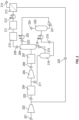
- the raw biogas feed stream is designated as (101).
- the raw biogas feed stream (101) is combined with the recycle stream (108) and is fed into the intake of the compressor (102).
- the combined gas stream is compressed to the target pressure determined by the pressure in the receiving pipeline followed by aftercooling and condensate separation (not shown).
- the compressed gas forms the first effluent stream (103).
- Compressed, cooled, and condensate separated, the raw biogas forming the first effluent stream (103) is fed into the lower part of the absorber (104), wherein it is contacted with the lean absorbent liquid.
- the first effluent stream is passed countercurrent to the lean absorbent liquid and forms the second effluent stream (105) depleted of carbon dioxide that is removed at the top of the column.
- tray columns or columns with regular or irregular structured packing can be used in the absorber vessel.
- the absorbent liquid temperature increases as a result of carbon dioxide absorption.
- the absorbent liquid can be cooled in the intermediate sections of the absorption vessel.
- the carbon dioxide concentration in the second effluent stream can be lowered by a factor of 2 to 15 as compared to the carbon dioxide concentration in the raw biogas feed stream.
- the regeneration of the rich absorbent stream (109) is carried out in a flash regeneration unit (110) by way of pressure reduction, wherein a fraction of the absorbed CO 2 is released leading to the liquid's temperature decrease.
- the absorption liquid characteristics, the liquid's loading, and temperature affect CO 2 desorption efficiency.
- the absorption liquid characteristics and process conditions are selected to remove at least 10 mass percent of carbon dioxide from the rich absorption liquid into the desorbed acid gas stream (111) by way of liquid pressure reduction to the atmospheric pressure.
- Absorbents that exhibit high CO 2 loading and show a strong dependence of CO 2 loading on pressure are preferred. It is known in the art to utilize aqueous amine solutions and physical absorbents as the absorption liquid media with high loading and lading pressure dependency.
- the lean absorbent liquid (113) is transported via pump (112) to the top of the absorption unit (104).
- the second effluent stream (105) is further treated in a membrane separation unit (106) that contains a polymeric membrane selective toward the removal of carbon dioxide, water vapor, and oxygen from methane.
- the carbon dioxide and water vapor still remaining in the second effluent stream are removed by permeation to generate the methane product stream (107) that meets the pipeline specification.
- the permeate stream (108) containing some residual methane is recycled to the front intake of the compressor (102).
- the membrane separation unit is comprised of one or more membrane separation modules arranged in series or in parallel.
- the modules are equipped with semipermeable membranes exhibiting CO 2 /CH 4 gas separation factor above 25, preferably above 35, and most preferably above 45, as measured at room temperature.
- the membranes further exhibit a highwater vapor/methane selectivity of 200 or more.
- membrane modules equipped with membranes exhibiting an oxygen/methane separation factor of above 5, preferably above 6, as measured at room temperature should be utilized.
- the gas separation efficiency is affected by the pressure ratio, i.e., the feed gas to the permeate gas pressure. To maintain the high pressure ratio, the permeate gas is collected at low pressure, not to exceed the compressor intake pressure.
- the membranes preferably operate in a counter-current mode to increase separation thermodynamic efficiency and reduce the volume of the recycled permeate gas. It is further in the scope of the invention to deploy membranes with different separation characteristics in sequential stages. It is known to utilize the permeate gas of the subsequent membrane stage as a purge gas on the permeate side of the preceding membrane stage to improve separation efficiency.
- the operation temperature in each membrane stage may be the same or different to optimize the overall separation efficiency.
- the gas may be preheated or cooled between stages to control the temperature. In some embodiments, it may be desirable to increase the separation efficiency of the membrane unit by the use of the permeate side sweep with a fraction of the retentate gas.
- Each module has a polymeric membrane with a defined high-pressure side and low-pressure side, each module has an inlet port connected to the high-pressure side, a retentate outlet port, and a permeate outlet port, therein the retentate outlet port providing an outlet for gas on the high-pressure side, and the permeate outlet port providing an outlet for gas on the low-pressure side.
- the feed gas is conveyed into the inlet port, the retentate gas is conveyed from the retentate outlet port, and the permeate gas is conveyed from the permeate port wherein a portion of the retentate gas from the retentate outlet is conveyed into the low-pressure permeate side while the remainder of the retentate gas from the retentate port is conveyed to a pipeline.
- the fraction of the retentate gas conveyed to the permeate side is controlled to affect retentate product purity.
- the feed raw biogas (101) with an initial CO 2 content of 40.6% (mol.), balance methane, and a volumetric flow of 1000 m 3 /h at normal atmospheric pressure conditions is treated by the method of the instant invention to remove carbon dioxide and generate pipeline quality methane.
- the feed biogas stream is combined with the recycle membrane permeate stream (108) to generate a feed flow of 1250 m 3 /h to the intake of the compressor.
- the gas is compressed in compressor (102) to 19 barg, the compressed gas is treated in an aftercooler to reduce the temperature to 40°C, and condensate is removed to form the first effluent stream (103).
- the compression step consumed about 280 kW of electrical power.
- the first effluent stream (103) was treated in the absorber unit (104) to remove the bulk amount of carbon dioxide and the second effluent stream (105) of a reduced CO 2 content was generated.
- the gas is flown counter-current to the absorption liquid (113) to maximize the mass transfer efficiency.
- the absorption liquid was comprised of 12.6% (mol) methyl diethanolamine, MDEA, and 2.1% (mol) piperazine (PZ) in water.
- the initial absorption liquid contained 10.1 mass % CO 2 and the liquid temperature was 45°C.
- a rich absorbent liquid stream (109) is formed that contains 13.4 mass % of CO 2 and the rich absorption liquid is discharged from the absorption system at a temperature of 60°C.
- the second effluent stream (105) contains 10.4% mol CO 2 .
- the second effluent gas stream was further treated in the membrane unit (106) to remove the remaining CO 2 and water vapor.
- the CO 2 retentate product gas concentration is reduced to 2.5% (mol.) with a water dew point of -10°C.
- the permeate stream (108) volume does not exceed 250 m 3 /h and is recycled to the intake of the compressor.
- the rich absorbent liquid (109) is regenerated in a flash regeneration unit (110) by way of pressure reduction to atmospheric pressure.
- the rich absorption liquid is further heated utilizing supplemental heat generated by the compressor to compensate for evaporation cooling.
- the heat provided by the compressor raises the liquid's temperature by up to 5 °C.
- the lean absorption liquid (113) is returned to the top of the absorption unit (104) and the carbon dioxide stream (111) is discharged to the atmosphere or recovered as a product.
- the absorption liquid is pumped by the recirculation pump (112) at a rate of 25 tons per hour with electrical energy consumption of 20 kW.
- the instant invention provides an overall reduction in the purification process energy consumption as compared to the state-of-the-art standalone membrane process, which has a permeate recycle as high as 50% of the raw biogas. Additional embodiments of the instant invention provide a further reduction in separation energy consumption by improved utilization of the secondary compressor heat and deploying an optimized multi-stage flash-regeneration system.
- the first pretreatment system can be a single-stage pretreatment or a combination of a number of pretreatment systems, such as a water wash system and an adsorption system, tailored to the removal of specific contaminants.
- the gas is combined with the gas recycle stream from the first regeneration unit and the combined stream is compressed in the compressor (205) equipped with an aftercooler and separator to form the first effluent stream (206).
- the first effluent stream is compressed to the target optimal processing pressure, preferably aligned with the pipeline pressure.
- the first pretreatment system may be omitted and contaminants removed following compression.
- This first effluent stream is processed in the second pretreatment system (207) to remove the remaining contaminants.
- the second pretreatment system can be a single-stage pretreatment or a combination of a number of pretreatment systems, such as adsorption systems tailored to the removal of specific contaminants.
- the pretreatment can further include an oxygen removal unit that overwise can affect the chemical stability of amine-based absorption systems.
- the thus pretreated gas stream is directed to the absorption system (208) optimized toward the removal of carbon dioxide.
- the first effluent stream is passed countercurrent to the lean absorbent liquid and forms the second effluent stream (209) depleted of carbon dioxide that is removed at the top of the column.
- tray columns or columns with regular or irregular structured packing can be used in the absorber vessel.
- the absorbent liquid temperature increases as a result of carbon dioxide absorption.
- the absorbent liquid can be cooled in the intermediate sections of the absorption vessel.
- the carbon dioxide concentration in the second effluent stream can be lowered by a factor of 2 to 15 as compared to the carbon dioxide concentration in the raw biogas feed stream.
- the second effluent stream is treated in a water removal unit (210) to reduce the water vapor dew point and prevent water condensation downstream.
- the water removal unit may include a chiller, a refrigeration unit, or other mechanism of water dew point suppression.
- the second effluent stream is optionally further treated in a third adsorption unit (211) to remove contaminants, such as absorption liquid vapors, that can affect membrane performance downstream.
- the second effluent stream is preheated in a heat exchanger (212) to the desired temperature optimal for membrane separation efficiency and the conditioned second effluent stream is directed into the membrane separation unit (213).
- the second effluent stream (209) is further treated in the membrane separation unit (213) that contains a polymeric membrane selective toward the removal of carbon dioxide, water vapor, and oxygen from methane.
- the carbon dioxide and water vapor still remaining in the second effluent stream are removed by permeation to generate the methane product stream (214) that meets the pipeline specification.
- the permeate stream (225) containing some residual methane is recycled to the front intake of the compressor (205).
- the rich absorption liquid (215) is removed from the bottom of the absorption unit (208) and regenerated in a multi-stage flash regeneration system that enables a deeper level of absorbent regeneration.
- the rich absorbent liquid (215) is directed into the first flash regeneration vessel (216), wherein initial regeneration at above atmospheric pressure takes place.
- the relatively small flash gas stream (217), containing carbon dioxide and methane, is recycled to the front end of the compressor to increase methane recovery.
- the rich absorbent liquid (218) that underwent a partial regeneration is removed from the bottom of the first flash regeneration vessel and directed to the second flash regeneration vessel (220).
- the stream (218) is heated by the application of secondary heat in a heat exchanger (219) prior to being directed into a flash vessel (220), wherein the pressure of the absorption liquid is reduced to atmospheric pressure and a lean absorption liquid is removed from the bottom of the vessel.
- the pump (221) directs the lean absorption liquid via a heat exchanger (222), wherein the lean absorption liquid is cooled and its temperature is reduced.
- the lean absorption liquid (223) is optionally filtered to remove impurities and degradation products and injected into the top section of the absorption vessel (208).
- the carbon dioxide stream (224) generated during flash regeneration in vessels (220) is vented to the atmosphere or processed as a separate product.
- the secondary heat from a compressor cooling system or another heat source is supplied to the rich absorption liquid in the flash regeneration system and the lean absorbent is cooled before being recycled to the gas absorption unit.
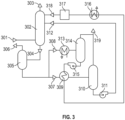
- a multi-stage flash regeneration system with a deeper level of absorbent regeneration is shown schematically in Figure 3 .
- the first effluent stream (301) containing carbon dioxide and methane is directed to the absorbent vessel (302), wherein the second effluent gas stream (303) depleted of carbon dioxide is generated.
- the second effluent stream undergoes additional treatment in a membrane system downstream (not shown).
- the rich absorbent liquid (304) is directed into the first flash regeneration vessel (305), wherein initial regeneration at above atmospheric pressure takes place.
- the relatively small flash gas stream (306), containing carbon dioxide and methane, is recycled to the front end of the compressor to increase methane recovery.
- the rich absorbent liquid that underwent a partial regeneration is removed from the bottom of the first flash regeneration vessel and split into two streams - a larger volume stream (307) and a smaller volume stream (308).
- the stream (308) is heated by the application of secondary heat in a heat exchanger (313) prior to being directed into a flash vessel (314), wherein the pressure of the absorption liquid is reduced to atmospheric pressure and a lean absorption liquid is removed from the bottom of the vessel.
- the pump (315) directs the lean absorption liquid via a heat exchanger (309), wherein the heat from the lean absorption liquid is transferred into the rich absorption liquid (307) to the heat exchanger (316), wherein the lean absorption liquid is cooled.
- the lean absorption liquid (318) is further filtered in the filter (317), where impurities and degradation products are removed and injected into the top section of the absorption vessel (302).
- the second rich absorption liquid (307) is heated via heat transfer from the lean absorption liquid (318) in the heat exchanger (309) and regenerated in a flash regeneration vessel (310) at atmospheric pressure.
- the lean absorption liquid is removed from the bottom of the vessel.
- This second larger-in-volume lean absorption liquid (312) is directed via pump (311) into the middle section of the absorption vessel (302).
- the second lean absorption liquid can be optionally cooled as well prior to being injected into the absorption vessel.
- the carbon dioxide streams generated during flash regeneration in vessels (310) and (314) are combined in a stream (319) and the stream is vented to the atmosphere or processed as a separate product.
- Some biogas streams may contain oxygen in addition to other contaminants.
- Oxygen removal may be required to prevent absorbent degradation and/or to meet the pipeline specification.
- Oxygen removal can be further carried out utilizing a thermal oxidizer unit.
- Catalytic combustion of oxygen utilizing the thermal oxidizer unit can be carried out upstream of the carbon dioxide absorption unit or downstream of the absorption or membrane unit.
Landscapes
- Chemical & Material Sciences (AREA)
- Engineering & Computer Science (AREA)
- Analytical Chemistry (AREA)
- General Chemical & Material Sciences (AREA)
- Oil, Petroleum & Natural Gas (AREA)
- Chemical Kinetics & Catalysis (AREA)
- Separation Using Semi-Permeable Membranes (AREA)
Applications Claiming Priority (1)
| Application Number | Priority Date | Filing Date | Title |
|---|---|---|---|
| US18/155,374 US11738302B1 (en) | 2023-01-17 | 2023-01-17 | Method of generating renewable natural gas |
Publications (1)
| Publication Number | Publication Date |
|---|---|
| EP4403248A1 true EP4403248A1 (de) | 2024-07-24 |
Family
ID=85505452
Family Applications (1)
| Application Number | Title | Priority Date | Filing Date |
|---|---|---|---|
| EP23160215.2A Pending EP4403248A1 (de) | 2023-01-17 | 2023-03-06 | Verfahren zur erzeugung von erneuerbarem erdgas |
Country Status (2)
| Country | Link |
|---|---|
| US (1) | US11738302B1 (de) |
| EP (1) | EP4403248A1 (de) |
Families Citing this family (3)
| Publication number | Priority date | Publication date | Assignee | Title |
|---|---|---|---|---|
| CA3119011A1 (en) * | 2021-05-18 | 2022-11-18 | 1304338 Alberta Ltd. | Method to dry a hydrocarbon gas stream |
| WO2025157794A1 (en) * | 2024-01-23 | 2025-07-31 | Evonik Operations Gmbh | Process and facility to remove carbon dioxide from a methane and carbon dioxide containing gas stream |
| US20250249402A1 (en) * | 2024-02-05 | 2025-08-07 | Saudi Arabian Oil Company | Systems and methods for eliminating flaring in amine sweetening |
Citations (16)
| Publication number | Priority date | Publication date | Assignee | Title |
|---|---|---|---|---|
| US4077779A (en) | 1976-10-15 | 1978-03-07 | Air Products And Chemicals, Inc. | Hydrogen purification by selective adsorption |
| US4421535A (en) | 1982-05-03 | 1983-12-20 | El Paso Hydrocarbons Company | Process for recovery of natural gas liquids from a sweetened natural gas stream |
| US4770676A (en) | 1986-05-16 | 1988-09-13 | Air Products And Chemicals, Inc. | Recovery of methane from land fill gas |
| US4857083A (en) | 1988-10-25 | 1989-08-15 | Air Products And Chemicals, Inc. | Vacuum swing adsorption process with vacuum aided internal rinse |
| US20040099138A1 (en) | 2002-11-21 | 2004-05-27 | L'air Liquide, Societe Anonyme A Directoire Et Conseil De Surveillance Pour L'etude Et | Membrane separation process |
| US6929680B2 (en) | 2003-09-26 | 2005-08-16 | Consortium Services Management Group, Inc. | CO2 separator method and apparatus |
| DE102005051952B3 (de) * | 2005-10-29 | 2006-12-21 | Dge Dr.-Ing. Günther Engineering Gmbh | Verfahren zur Herstellung von Methan und flüssigem Kohlendioxid aus Raffinerie- und/oder Biogas |
| WO2007080169A2 (en) * | 2006-01-13 | 2007-07-19 | Gasrec Limited | Methane recovery from a landfill gas |
| US20080134754A1 (en) * | 2006-12-11 | 2008-06-12 | Funk Michael N | Process for converting biogas to a pipeline grade renewable natural gas |
| US7442233B2 (en) | 2005-07-06 | 2008-10-28 | Basf Catalysts Llc | Integrated heavy hydrocarbon removal, amine treating and dehydration |
| US8454727B2 (en) | 2010-05-28 | 2013-06-04 | Uop Llc | Treatment of natural gas feeds |
| US8999038B2 (en) | 2010-07-01 | 2015-04-07 | Evonik Fibres Gmbh | Process for separation of gases |
| WO2017099581A2 (en) * | 2015-12-08 | 2017-06-15 | Frames Renewable Energy Solutions B.V. | Process for the purification of a gas |
| US20180112142A1 (en) * | 2016-10-20 | 2018-04-26 | Iogen Corporation | Method and system for providing upgraded biogas |
| EP3628390A1 (de) * | 2018-09-26 | 2020-04-01 | Hysytech S.r.l. | Biogasbehandlungsanordnung |
| US20210060486A1 (en) * | 2020-11-11 | 2021-03-04 | Waga Energy | Facility For Producing Gaseous Biomethane By Purifying Biogas From Landfill Combining Membranes, Cryodistillation And Deoxo |
Family Cites Families (1)
| Publication number | Priority date | Publication date | Assignee | Title |
|---|---|---|---|---|
| US8282707B2 (en) | 2010-06-30 | 2012-10-09 | Uop Llc | Natural gas purification system |
-
2023
- 2023-01-17 US US18/155,374 patent/US11738302B1/en active Active
- 2023-03-06 EP EP23160215.2A patent/EP4403248A1/de active Pending
Patent Citations (16)
| Publication number | Priority date | Publication date | Assignee | Title |
|---|---|---|---|---|
| US4077779A (en) | 1976-10-15 | 1978-03-07 | Air Products And Chemicals, Inc. | Hydrogen purification by selective adsorption |
| US4421535A (en) | 1982-05-03 | 1983-12-20 | El Paso Hydrocarbons Company | Process for recovery of natural gas liquids from a sweetened natural gas stream |
| US4770676A (en) | 1986-05-16 | 1988-09-13 | Air Products And Chemicals, Inc. | Recovery of methane from land fill gas |
| US4857083A (en) | 1988-10-25 | 1989-08-15 | Air Products And Chemicals, Inc. | Vacuum swing adsorption process with vacuum aided internal rinse |
| US20040099138A1 (en) | 2002-11-21 | 2004-05-27 | L'air Liquide, Societe Anonyme A Directoire Et Conseil De Surveillance Pour L'etude Et | Membrane separation process |
| US6929680B2 (en) | 2003-09-26 | 2005-08-16 | Consortium Services Management Group, Inc. | CO2 separator method and apparatus |
| US7442233B2 (en) | 2005-07-06 | 2008-10-28 | Basf Catalysts Llc | Integrated heavy hydrocarbon removal, amine treating and dehydration |
| DE102005051952B3 (de) * | 2005-10-29 | 2006-12-21 | Dge Dr.-Ing. Günther Engineering Gmbh | Verfahren zur Herstellung von Methan und flüssigem Kohlendioxid aus Raffinerie- und/oder Biogas |
| WO2007080169A2 (en) * | 2006-01-13 | 2007-07-19 | Gasrec Limited | Methane recovery from a landfill gas |
| US20080134754A1 (en) * | 2006-12-11 | 2008-06-12 | Funk Michael N | Process for converting biogas to a pipeline grade renewable natural gas |
| US8454727B2 (en) | 2010-05-28 | 2013-06-04 | Uop Llc | Treatment of natural gas feeds |
| US8999038B2 (en) | 2010-07-01 | 2015-04-07 | Evonik Fibres Gmbh | Process for separation of gases |
| WO2017099581A2 (en) * | 2015-12-08 | 2017-06-15 | Frames Renewable Energy Solutions B.V. | Process for the purification of a gas |
| US20180112142A1 (en) * | 2016-10-20 | 2018-04-26 | Iogen Corporation | Method and system for providing upgraded biogas |
| EP3628390A1 (de) * | 2018-09-26 | 2020-04-01 | Hysytech S.r.l. | Biogasbehandlungsanordnung |
| US20210060486A1 (en) * | 2020-11-11 | 2021-03-04 | Waga Energy | Facility For Producing Gaseous Biomethane By Purifying Biogas From Landfill Combining Membranes, Cryodistillation And Deoxo |
Non-Patent Citations (7)
| Title |
|---|
| A. MAKARUK ET AL., SEPARATION AND PURIFICATION TECHNOLOGY, vol. 74, 2010, pages 83 - 92 |
| ANJAN K. DATTA ET AL., JOURNAL OF MEMBRANE SCIENCE, vol. 283, 2006, pages 291 - 300 |
| B. FREEMAN ET AL., ENERGY PROCEDIA, vol. 63, 2014, pages 605 - 613 |
| EVONIK: "SEPURAN Green Membrane technology for efficient biogas upgrading", 10 August 2023 (2023-08-10), pages 1 - 16, XP093072751, Retrieved from the Internet <URL:https://products.evonik.com/assets/44/34/SEPURAN_Green_for_upgrading_biogas_en_EN_Asset_684434.pdf> * |
| G. ROCHELLE ET AL., CHEMICAL ENGINEERING JOURNAL, vol. 171, 2011, pages 725 - 733 |
| R. BAKER ET AL., IND. ENG. CHEM. RES., vol. 47, 2008, pages 2109 - 2121 |
| S. MIRZAEI, REV CHEM ENG, 2015 |
Also Published As
| Publication number | Publication date |
|---|---|
| US11738302B1 (en) | 2023-08-29 |
Similar Documents
| Publication | Publication Date | Title |
|---|---|---|
| US11738302B1 (en) | Method of generating renewable natural gas | |
| RU2730344C1 (ru) | Извлечение гелия из природного газа | |
| US9205382B2 (en) | Carbon dioxide separation system | |
| AU2008336265B2 (en) | A plant and process for recovering carbon dioxide | |
| KR101529129B1 (ko) | 고순도 메탄가스의 분리를 위한 다단계 막분리 정제공정 및 장치 | |
| KR101388266B1 (ko) | 고로가스의 분리방법 및 장치 | |
| US20040099138A1 (en) | Membrane separation process | |
| US20110185896A1 (en) | Gas purification processes | |
| US11701612B2 (en) | Multi-stage PSA process to remove contaminant gases from raw methane streams | |
| Czarnota et al. | Carbon dioxide separation technologies | |
| EP4509204A1 (de) | Anlage und verfahren zur herstellung von erneuerbarem erdgas aus biogas | |
| WO2022101324A1 (en) | Facility for producing gaseous methane by purifying biogas from landfill, combining membranes and cryogenic distillation for landfill biogas upgrading | |
| CN102665861A (zh) | 气体纯化结构和方法 | |
| CN107148398A (zh) | 从气态混合物中分离产物气体的方法 | |
| KR20090051168A (ko) | 수소 정제 방법 | |
| CN102883791A (zh) | 从天然气中清除污染物的方法 | |
| CN112107963A (zh) | 通过吸附单元和膜分离单元的组合处理包含voc和二氧化碳的甲烷料流 | |
| US20130319231A1 (en) | Integrated system for acid gas removal | |
| CN117101335A (zh) | 一种低压低能耗烟气二氧化碳回收系统及回收工艺 | |
| US9051228B2 (en) | LNG pretreatment | |
| KR101658448B1 (ko) | 천연가스에 포함된 산성가스 및 수분 제거를 위한 다단계 혼성 장치 및 방법 | |
| US20240343578A1 (en) | Helium separation and recovery process | |
| EP4454736A1 (de) | Verfahren zur entfernung von sauren gasen aus kohlenwasserstoffgasen | |
| AU2013231263A1 (en) | Combined gas processing | |
| WO2025157794A1 (en) | Process and facility to remove carbon dioxide from a methane and carbon dioxide containing gas stream |
Legal Events
| Date | Code | Title | Description |
|---|---|---|---|
| PUAI | Public reference made under article 153(3) epc to a published international application that has entered the european phase |
Free format text: ORIGINAL CODE: 0009012 |
|
| STAA | Information on the status of an ep patent application or granted ep patent |
Free format text: STATUS: REQUEST FOR EXAMINATION WAS MADE |
|
| 17P | Request for examination filed |
Effective date: 20230306 |
|
| AK | Designated contracting states |
Kind code of ref document: A1 Designated state(s): AL AT BE BG CH CY CZ DE DK EE ES FI FR GB GR HR HU IE IS IT LI LT LU LV MC ME MK MT NL NO PL PT RO RS SE SI SK SM TR |