EP4403157A1 - Massagegerät - Google Patents
Massagegerät Download PDFInfo
- Publication number
- EP4403157A1 EP4403157A1 EP23211161.7A EP23211161A EP4403157A1 EP 4403157 A1 EP4403157 A1 EP 4403157A1 EP 23211161 A EP23211161 A EP 23211161A EP 4403157 A1 EP4403157 A1 EP 4403157A1
- Authority
- EP
- European Patent Office
- Prior art keywords
- shell
- massage
- moving space
- lateral wall
- massage member
- Prior art date
- Legal status (The legal status is an assumption and is not a legal conclusion. Google has not performed a legal analysis and makes no representation as to the accuracy of the status listed.)
- Granted
Links
Images





Classifications
-
- A—HUMAN NECESSITIES
- A61—MEDICAL OR VETERINARY SCIENCE; HYGIENE
- A61H—PHYSICAL THERAPY APPARATUS, e.g. DEVICES FOR LOCATING OR STIMULATING REFLEX POINTS IN THE BODY; ARTIFICIAL RESPIRATION; MASSAGE; BATHING DEVICES FOR SPECIAL THERAPEUTIC OR HYGIENIC PURPOSES OR SPECIFIC PARTS OF THE BODY
- A61H19/00—Massage for the genitals; Devices for improving sexual intercourse
- A61H19/30—Devices for external stimulation of the genitals
-
- A—HUMAN NECESSITIES
- A61—MEDICAL OR VETERINARY SCIENCE; HYGIENE
- A61H—PHYSICAL THERAPY APPARATUS, e.g. DEVICES FOR LOCATING OR STIMULATING REFLEX POINTS IN THE BODY; ARTIFICIAL RESPIRATION; MASSAGE; BATHING DEVICES FOR SPECIAL THERAPEUTIC OR HYGIENIC PURPOSES OR SPECIFIC PARTS OF THE BODY
- A61H19/00—Massage for the genitals; Devices for improving sexual intercourse
- A61H19/30—Devices for external stimulation of the genitals
- A61H19/34—For clitoral stimulation
-
- A—HUMAN NECESSITIES
- A61—MEDICAL OR VETERINARY SCIENCE; HYGIENE
- A61H—PHYSICAL THERAPY APPARATUS, e.g. DEVICES FOR LOCATING OR STIMULATING REFLEX POINTS IN THE BODY; ARTIFICIAL RESPIRATION; MASSAGE; BATHING DEVICES FOR SPECIAL THERAPEUTIC OR HYGIENIC PURPOSES OR SPECIFIC PARTS OF THE BODY
- A61H19/00—Massage for the genitals; Devices for improving sexual intercourse
- A61H19/40—Devices insertable in the genitals
- A61H19/44—Having substantially cylindrical shape, e.g. dildos
-
- A—HUMAN NECESSITIES
- A61—MEDICAL OR VETERINARY SCIENCE; HYGIENE
- A61H—PHYSICAL THERAPY APPARATUS, e.g. DEVICES FOR LOCATING OR STIMULATING REFLEX POINTS IN THE BODY; ARTIFICIAL RESPIRATION; MASSAGE; BATHING DEVICES FOR SPECIAL THERAPEUTIC OR HYGIENIC PURPOSES OR SPECIFIC PARTS OF THE BODY
- A61H23/00—Percussion or vibration massage, e.g. using supersonic vibration; Suction-vibration massage; Massage with moving diaphragms
- A61H23/02—Percussion or vibration massage, e.g. using supersonic vibration; Suction-vibration massage; Massage with moving diaphragms with electric or magnetic drive
- A61H23/0254—Percussion or vibration massage, e.g. using supersonic vibration; Suction-vibration massage; Massage with moving diaphragms with electric or magnetic drive with rotary motor
-
- A—HUMAN NECESSITIES
- A61—MEDICAL OR VETERINARY SCIENCE; HYGIENE
- A61H—PHYSICAL THERAPY APPARATUS, e.g. DEVICES FOR LOCATING OR STIMULATING REFLEX POINTS IN THE BODY; ARTIFICIAL RESPIRATION; MASSAGE; BATHING DEVICES FOR SPECIAL THERAPEUTIC OR HYGIENIC PURPOSES OR SPECIFIC PARTS OF THE BODY
- A61H23/00—Percussion or vibration massage, e.g. using supersonic vibration; Suction-vibration massage; Massage with moving diaphragms
- A61H23/02—Percussion or vibration massage, e.g. using supersonic vibration; Suction-vibration massage; Massage with moving diaphragms with electric or magnetic drive
- A61H23/0254—Percussion or vibration massage, e.g. using supersonic vibration; Suction-vibration massage; Massage with moving diaphragms with electric or magnetic drive with rotary motor
- A61H23/0263—Percussion or vibration massage, e.g. using supersonic vibration; Suction-vibration massage; Massage with moving diaphragms with electric or magnetic drive with rotary motor using rotating unbalanced masses
-
- A—HUMAN NECESSITIES
- A61—MEDICAL OR VETERINARY SCIENCE; HYGIENE
- A61H—PHYSICAL THERAPY APPARATUS, e.g. DEVICES FOR LOCATING OR STIMULATING REFLEX POINTS IN THE BODY; ARTIFICIAL RESPIRATION; MASSAGE; BATHING DEVICES FOR SPECIAL THERAPEUTIC OR HYGIENIC PURPOSES OR SPECIFIC PARTS OF THE BODY
- A61H2201/00—Characteristics of apparatus not provided for in the preceding codes
- A61H2201/12—Driving means
- A61H2201/1207—Driving means with electric or magnetic drive
- A61H2201/1215—Rotary drive
-
- A—HUMAN NECESSITIES
- A61—MEDICAL OR VETERINARY SCIENCE; HYGIENE
- A61H—PHYSICAL THERAPY APPARATUS, e.g. DEVICES FOR LOCATING OR STIMULATING REFLEX POINTS IN THE BODY; ARTIFICIAL RESPIRATION; MASSAGE; BATHING DEVICES FOR SPECIAL THERAPEUTIC OR HYGIENIC PURPOSES OR SPECIFIC PARTS OF THE BODY
- A61H2201/00—Characteristics of apparatus not provided for in the preceding codes
- A61H2201/12—Driving means
- A61H2201/1207—Driving means with electric or magnetic drive
- A61H2201/123—Linear drive
-
- A—HUMAN NECESSITIES
- A61—MEDICAL OR VETERINARY SCIENCE; HYGIENE
- A61H—PHYSICAL THERAPY APPARATUS, e.g. DEVICES FOR LOCATING OR STIMULATING REFLEX POINTS IN THE BODY; ARTIFICIAL RESPIRATION; MASSAGE; BATHING DEVICES FOR SPECIAL THERAPEUTIC OR HYGIENIC PURPOSES OR SPECIFIC PARTS OF THE BODY
- A61H2201/00—Characteristics of apparatus not provided for in the preceding codes
- A61H2201/14—Special force transmission means, i.e. between the driving means and the interface with the user
- A61H2201/1418—Cam
-
- A—HUMAN NECESSITIES
- A61—MEDICAL OR VETERINARY SCIENCE; HYGIENE
- A61H—PHYSICAL THERAPY APPARATUS, e.g. DEVICES FOR LOCATING OR STIMULATING REFLEX POINTS IN THE BODY; ARTIFICIAL RESPIRATION; MASSAGE; BATHING DEVICES FOR SPECIAL THERAPEUTIC OR HYGIENIC PURPOSES OR SPECIFIC PARTS OF THE BODY
- A61H2201/00—Characteristics of apparatus not provided for in the preceding codes
- A61H2201/14—Special force transmission means, i.e. between the driving means and the interface with the user
- A61H2201/1481—Special movement conversion means
- A61H2201/149—Special movement conversion means rotation-linear or vice versa
-
- A—HUMAN NECESSITIES
- A61—MEDICAL OR VETERINARY SCIENCE; HYGIENE
- A61H—PHYSICAL THERAPY APPARATUS, e.g. DEVICES FOR LOCATING OR STIMULATING REFLEX POINTS IN THE BODY; ARTIFICIAL RESPIRATION; MASSAGE; BATHING DEVICES FOR SPECIAL THERAPEUTIC OR HYGIENIC PURPOSES OR SPECIFIC PARTS OF THE BODY
- A61H2201/00—Characteristics of apparatus not provided for in the preceding codes
- A61H2201/16—Physical interface with patient
- A61H2201/1657—Movement of interface, i.e. force application means
- A61H2201/1676—Pivoting
-
- A—HUMAN NECESSITIES
- A61—MEDICAL OR VETERINARY SCIENCE; HYGIENE
- A61H—PHYSICAL THERAPY APPARATUS, e.g. DEVICES FOR LOCATING OR STIMULATING REFLEX POINTS IN THE BODY; ARTIFICIAL RESPIRATION; MASSAGE; BATHING DEVICES FOR SPECIAL THERAPEUTIC OR HYGIENIC PURPOSES OR SPECIFIC PARTS OF THE BODY
- A61H2201/00—Characteristics of apparatus not provided for in the preceding codes
- A61H2201/16—Physical interface with patient
- A61H2201/1683—Surface of interface
- A61H2201/169—Physical characteristics of the surface, e.g. material, relief, texture or indicia
- A61H2201/1695—Enhanced pressure effect, e.g. substantially sharp projections, needles or pyramids
Definitions
- the present invention relates to the technical field of massage devices, and in particular to a massage device with a swinging massage member.
- the massage device in the related art generally includes motor and a massage head driven by the motor.
- the massage head does linear reciprocating motion to hit a part of the human body that needs to be massaged, such as the waist, the neck and the like.
- Such massage device is relatively simple in actions, and the massage head thereof is subject to the resistance of the massaged part of the human body during operation, so it is difficult to play good massage effect and accordingly the massage experience is not ideal.
- An object of the present invention is to provide a massage device that is capable of playing good massage effect even under the resistance of the massaged part, thereby improving the massage experience.
- a massage device including:
- a stimulation member is arranged in another chamber of the shell, wherein the another chamber is defined by the interior surface of the shell and is separated from the moving space.
- the stimulation member is a vibration motor.
- the another chamber is defined at an end of the shell which is configured to be inserted into the vagina during in use.
- the moving space is located between the stimulation member and the driving member along the insertion direction of the shell.
- the another chamber is defined in a branch of the shell which extends curvedly from a rear end of the moving space of the shell to an upper side of the massage member, the branch is configured to be located outside of the vagina and the stimulation member arranged in the another chamber is configured to generate vibration effect to the clitoris during in use.
- the moving space further extends through a second exterior side of the lateral wall to the outside environment, and wherein the second and first exterior sides of the lateral wall are opposite to each other and exposed to the outside environment.
- the moving space extends through the first and second exterior sides of the lateral wall along a swing direction of the massage member which is substantially perpendicular to the insertion direction of the shell, and wherein when the massage member swings, the massage portion of the massage member reciprocates in three different positions, the three different positions include the first position inside the moving space of the shell, the second position out of the lateral wall via the opening at the first exterior side of the lateral wall, and a third position out of the lateral wall via the opening at the second exterior side of the lateral wall.
- a thickness of the massage portion of the massage member in a lateral direction of the shell is less than a depth of the moving space in the lateral direction of the shell.
- a shape of the massage member is different from that of the moving space, and a gap is defined between an outer surface of the massage member and the interior surface of the shell, wherein a width of the gap changes along a circumferential direction.
- the moving space is defined at a middle portion of the shell and is closed along a circumferential direction.
- a plurality of bulges are formed on an outer surface of the massage member.
- the driving member is a rotary motor, and a cam is connected between the rotary motor and the massage member; and wherein the massage member includes a soft cover and a hard core embedded in the soft cover, the hard core is rotatably connected to the shell, and the cam is movably connected to the hard core.
- the hard core defines a groove
- the cam has a driving shaft extending into the groove
- the groove is configured such that movement of the driving shaft along a swinging direction of the massage member is limited, and movement of the driving shaft along a direction perpendicular to the swinging direction of the massage member is allowed.
- the massage device defines the moving space in the shell for providing sufficient space for the swinging of the massage member, so that the massage device is capable of generating strong force to the massaged part even under the resistance of the massaged part, thereby playing good massage effect.
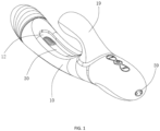
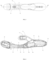
- the massage device includes a shell 10, a driving member 20 mounted in the shell 10 and a massage member 30 connected to the driving member 20 in a transmission way.
- the shell 10 defines a moving space 12 therein.
- the moving space 12 communicates with the outside environment.
- the massage member 30 extends into the moving space 12, and moves relative to the shell 10 under the action of the driving member 20.
- at least a portion of the massage member 30 is capable of extending beyond the moving space 12 of the shell 10 to the outside environment, so as to massage a corresponding part of the human body out of the shell 10.
- the massage device defines the moving space 12 in the shell 10, the massage member 30 extends into the moving space 12, and the driving member 20 makes the massage member 30 move relative to the shell 10 in the form of swinging, so that at least a portion of the massage member 30, particularly a massage portion of the massage member 30 swings beyond the moving space 12 of the shell 10 to hit the corresponding part of the human body out of the shell 10, thereby performing massage to the human body.
- the design of the moving space 12 in the shell 10 provides sufficient space for the swinging of the massage member 30, and thus the massage device is capable of generating strong force to the massaged part even under the resistance of the massaged part, thereby playing good massage effect.
- the massage member 30 is an elastic structure and is capable of generating deformation when it hits the massaged part, so that the shape of the massage member 30 after deformed matches with the shape of the massaged part. In this way, a contact area of the massage member 30 and the massaged part is enlarged, and thus the massage effect is further improved.
- the entire massage member 30 may be made of soft materials, such as silica, rubber and the like.
- an outer portion of the massage member 30 for touching the massaged part is made of soft materials, and an inner portion of the massage member 30 embedded in the outer portion is made of hard materials, such as plastic, metal and etc.
- the massage member 30 swings in the moving space 12 along the depth direction, i.e., along the longitudinal direction to up and down in the moving space 12.
- the thickness T of the massage member 30 along the longitudinal direction is less than the depth D of the moving space 12/the thickness of the shell 10 along the longitudinal direction, and the massage member 30 is completely received in the moving space 12 when it is not work.
- the thickness difference of the massage member 30 and the shell 10 provides a space therebetween along the swinging direction of the massage member 30, thus the massage member 30 is capable of swinging even the massaged part is nestled to the outer surface of the shell 10, thereby ensuring the massage experience.
- the massage member 30 is generally elongated and column-shaped.
- the thickness T of the massage member 30 is preferably 1 mm ⁇ 150mm, the width of the massage member 30 is preferably 1 mm ⁇ 150mm, and the length of the massage member 30 is preferably 5 ⁇ 150mm, so as to make the touching area of the massage member 30 appropriate when it hit the massaged part.
- One end of the massage member 30 is connected to the driving member 20, and the other end of the massage member 30 is free.
- the free end of the massage member 30 acts as a massage head 32 which serves as the massage portion, swinging out of the moving space 12 to hit the massaged part.
- the entire massage member 30 is constructed as a single pendulum, and the massage head 32 may obtain a big swing amplitude even the swing angle of the massage member 30 is small.
- the massage portion is formed as the free end of the massage member, however, in other embodiments, the massage member may also be a portion other than the free end, for example, a middle portion of the massage member. In some other embodiments, a plurality of massage portions may be provided.
- a plurality of bulges 34 are formed on the outer surface of the massage head 32 of the massage member 30 for improving stimulation to the massaged part.
- the bulges 34 may be formed on the entire outer surface of the massage member 30.
- the bulges 34 are integrally formed with the massage member 30, for example by injection molding.
- the bulges 34 may be formed separately and then assembled to the massage member 30 by bonding.
- the massage member 30 is less than the moving space 12 of the shell 10 in lateral dimensions, and a gap 40 is defined between an outer surface of the massage member 30 and an inner surface of the shell 10 surrounding the moving space 12.
- the gap 40 makes the swinging of the massage member 30 in the moving space 12 not interfere with the shell 10.
- the width W of the gap 40 is designed to be not less than 0.5mm to ensure that the massage member 30 swings freely in the moving space 12, and on the other hand, the width W of the gap 40 is designed to be less than 100mm to avoid wasting space and reduce the entire dimensions of the massage device.
- the width W of the gap 40 may be 0.5mm, 1.5mm, 3mm, ..., 50mm, ..., 99mm or 100mm.
- the moving space 12 has a shape similar to that of the massage member 30.
- the width W of the gap 40 between the outer surface of the massage member 30 and the inner surface of the shell 10 is substantially constant along a circumferential direction.
- the moving space 12 is generally race-track shaped.
- the inner surface of the shell 10 is continuous along the circumferential direction, and the moving space 12 is closed circumferentially.
- the moving space 12 is a through hole extending through two opposite sides (top and bottom sides as viewed from FIG. 2 ) of the shell 10.
- the depth D of the moving space 12 is the same as the thickness of the shell 10, preferably ranges from 1mm to 100mm.
- the massage member 30 swings along the depth direction of the moving space 12, which can not only swing upwardly to the outside of the shell 10, but also swing downwardly to the outside of the shell 10. That is, the massage member 30 is capably of massaging two different parts of the human body which are located at two opposite sides of the shell 10 at the same time, which is more suitable for use in the human body to massage the cavity, such as the vagina.
- the moving space 12 may be a blind hole extending through only one side, such as the top side of the shell 10, as shown in FIG. 7 .
- the depth D of the moving space 12 is less than the thickness of the shell 10.
- the massage device with the blind hole is more suitable for massaging the body surface, such as the waist, the neck and the like. It should be noted that the massage device with the blind hole may also be used for massaging the cavity of the human body, and the massage device with the through hole may also be used for massaging the body surface.
- the moving space 12 may have a shape different from that of the massage member 30, and thus the width W of the gap 40 may be variable along the circumferential direction.
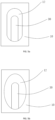
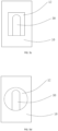
- the shape of the moving space 12 may be regular or irregular, specifically may be any one of circle, semicircle, ellipse, square, rectangle, triangle, polygon, D-shape, C-shaped, kidney-shaped, heart-shaped, gourd-shaped, briolette, and etc., or may be a combination of at least two of them.
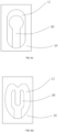
- the moving space 12 shown in FIG. 5a is generally kidney-shaped
- the moving space 12 shown in FIG. 5b is generally elliptical
- the moving space 12 shown in FIG. 5c is generally rectangular
- the moving space 12 shown in FIG. 5d is generally circular
- the moving space 12 shown in FIG. 5e is generally irregular
- the moving space 12 shown in FIG. 5f is generally a combination of a triangle and a rectangle. It should be understood that the shape of the moving space 12 may be set according to needs, which is not limited to the embodiments.
- the moving space 12 may be open in the circumferential direction. That is, the inner surface of the shell 10 surrounding the moving space 12 is discontinuous along the circumferential direction.
- a circumferential opening 14 is defined in the shell 10 and communicates with the moving space 12.
- the circumferential opening 14 is aligned with the massage head 32 along the longitudinal direction of the massage member 30, and the massage head 32 extends out of the moving space 12 through the circumferential opening 14,.
- the massage head 32 of the massage member 30 are capable of hitting corresponding parts of the human body, which means that the area being massaged at the same time is further increased.
- the entire massage member 30 may be accommodated in the moving space 12 even the moving space 12 is open circumferentially.
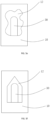
- FIG. 5i shows that the moving space 12 is generally briolette and open circumferentially, whilst the entire massage member 30 is in the moving space 12.
- the massage member 30 accommodated in the moving space 12 may be deviated from the circumferential opening 14.
- FIG. 5i shows that the moving space 12 is generally C-shaped, and the massage member 30 is generally column-shaped and arranged parallel to the circumferential opening 14 of the moving space 12.
- the shape of the massage member 30 may be regular or irregular, specifically may be any one of circle, semicircle, ellipse, square, rectangle, triangle, polygon, D-shape, C-shaped, kidney-shaped, heart-shaped, gourd-shaped, branch-shaped, and etc., or may be a combination of at least two of them.
- the massage member 30 shown in FIG. 6a is generally column-shaped with the massage head thereof being rounded
- the massage member 30 shown in FIG. 6b is generally irregular
- the massage member 30 shown in FIG. 6c is generally a combination of a column and a circle
- the massage member 30 shown in FIG. 6d is generally branch-shaped. It should be understood that the shape of the massage member 30 may be set according to needs, which is not limited to the embodiments.
- the shape of the massage member 30 and the shape of the moving space 12 can be selected arbitrarily, as long as the massage member 30 is movable in the moving space 12.
- FIGs. 5a-5j show the moving spaces 12 of different shapes with the same massage member 30
- FIGs. 6a-6d show the moving spaces 12 of different shapes with the massage member 30 of different shapes. It should be noted that the present invention does not impose any restrictions on the shapes of the moving space 12 and massage member 30, and does not impose any restrictions on the combination of the shapes of the moving space 12 and massage member 30.
- the shell 10 is elongated and the moving space 12 is defined in a middle portion of the shell 10 along the longitudinal direction.
- the moving space 12 in the middle portion of the shell 10 is closed circumferentially, and the shell 10 forms two supporting arms 16 at two opposite lateral sides (i.e., left and right sides) of the moving space 12.
- the supporting arms 16 enhance the strength of the shell 10 and thus can provide effective support for the massage member 30 even it swings rapidly and/or greatly.
- the width of the supporting arm 16 ranges from 1mm to 150mm, which is conducive to the miniaturization of the massage device, particularly miniaturization of the diameter of the massage device, so that the massage device can be used for massage of narrow and small parts, such as the cavity of the human body.
- the moving space 12 may be defined at an end portion of the shell 10.
- the moving space 12 may be closed in the circumferential direction or be open in the circumferential direction.
- the shell 10 may be designed to have an outer profile according to its application scenarios.
- the shell 10 may be shaped as the cavity of the human body, for example shaped as the vagina, as shown in FIGs. 1-4 .
- the shell 10 may be any shape, such as column-shaped, block-shaped, disc-shaped, branch-shaped, and etc.
- the shell 10 may be provided with a handle for holding, thereby facilitating the users to place the massage device onto any part of the human body.
- the shell 10 may be provided with a wearable member, such as a telescopic belt, a bandage with a buckle, and the like. The whole massage device can be worn to the neck, the waist, the arm, the leg, and etc. through the wearable member, thereby freeing hands of the users.
- the shell 10 is a double-layer structure, and includes an inner shell 10a and an outer shell 10b covering the whole inner shell 10a.
- the inner shell 10a is made of hard materials, such as plastic, metal, wood, and etc.
- the outer shell 10b is made of soft materials, such as silicone, rubber, and etc.
- the inner shell 10a inside the outer shell 10b not only provides support for the outer shell 10b, but also provides a receiving space for mounting the driving member 20.
- the outer shell 10b which is used to touch the massaged part directly, preferably has a smooth outer surface, thereby the massage device in whole has high strength and comfortable use experience.
- the inner shell 10a is formed by injection molding as two pieces and then assembly together by snap-fitting, screws, and etc., which facilitates assembly of the elements inside the shell 10, such as the driving member 20.
- the outer shell 10b is formed by 2nd injection molding as one piece and covering the inner shell 10a after the inner shell 10a and the elements inside the inner shell 10a are assembled together.
- the integral outer shell 10b is beneficial to the waterproof and dustproof of the present massage device, so that the massage device can be used underwater or in the cavity of the human body.
- the inner shell 10a may be molded as one piece. In this case, elements mounted inside the inner shell 10a are arranged in the mold and then injects the inner shell 10a.
- the outer shell 10b may be molded as two or more pieces and then assembled together. In this case, the shell 10 is detachable for replacing elements therein, which is good for maintenance of the massage device.
- the inner shell 10a may be the same as the outer shell 10b, and thus the shell 10 has two different layers in any positions.
- the inner shell 10a may be different from the outer shell 10b in local areas, and thus the local areas of the shell 10 may be one layer, i.e., without the layer of the hard inner shell 10a.
- the moving space 12 is defined at a position of the hard outer shell 10b with the soft inner shell 10a formed therein, thus the solid portion surrounding the moving space 12 is constructed of two layers and the strength thereof is high enough to support the swinging of the massage member 30. It should be understood that: in some cases where the requirements for the use environment are not high, the moving space 12 may be formed at a position of the outer shell 10b without the inner shell 10a formed therein.
- the shell 10 may be a single-layer structure with certain hardness.
- the massage device further includes a vibration motor 50.
- the vibration motor 50 is arranged in a front end of the shell 10 for generating high-frequency vibration.
- the vibration motor 50 in the front end of the shell 10 generates vibration effect to the vaginal wall, and the massage member 30 generates scratch effect to the vaginal wall at the same time, which can multiply the stimulation effect to the users.
- the massage device includes two vibration motors 50, 52, one of which is arranged in the front end of the shell 10, and the other is arranged in a branch 19 of the shell 10 which extends curvedly from a rear end of the moving space 12 of the shell 10 to an upper side of the massage member 30.
- the vibration motor 50 in the front end of the shell 10 generates vibration effect to the vaginal wall
- the massage member 30 generates scratch effect to the vaginal wall
- the vibration motor 52 in the branch 19 of the shell 10 generates vibration effect to the clitoris, which can maximize the stimulation effect to the users.
- the driving member 20 is used to generate power to make the massage member 30 move relative to the shell 10, and can be motor, cylinder and the like.
- the driving member 20 is a rotary motor or a linear motor.
- a transmission member 22 is arranged between the driving member 20 and the massage member 30.
- the transmission member 22 may be gear mechanism, pulley mechanism, crank mechanism, cam mechanism, turbine mechanism, and etc., which not only transmits power from the driving member 20 to the massage member 30, but also change the movement mode therebetween, such as change the rotation of the driving member 20 to the swinging of the massage member 30.
- the driving member 20 is a rotary motor
- the transmission member 22 is a cam.
- the rotary motor 20, the cam 22 and the massage member 30 cooperatively construct a massage module.
- the rotary shaft 21 of the rotary motor 20 is connected to a central portion of the cam 22, and a driving shaft 23 extends out from a periphery of the cam 22 to connect the massage member 30.
- Both the rotary shaft 21 and driving shaft 23 extend generally parallel to the longitudinal direction of the shell 10, but the driving shaft 23 is eccentric with respect to the rotary shaft 21.
- the driving shaft 23 revolves around the rotary shaft 21 to generate movement along both the thickness direction and the width direction of the shell 10.
- the driving member 20 may be a linear motor, which has an output shaft rotationally connected to the massage member 30. During the reciprocating motion of the linear motor, it drives the massage member 30 to swing up and down. In this case, the massaged parts are massaged in the form of slapping.
- the driving member 20 may be a vibration motor, which directly transmits vibration to the massage member 30.
- the driving member 20 and the massage member 30 may be connected in a transmission way but in a manner of non-contact.
- the driving member 20 may be in the form of an electromagnet
- the massage member 30 is connected to the driving member 20 by magnetic force.
- the polarity of the electromagnet is changed according to the current directions applied to driving member 20, making the magnetic force between the driving member 20 and the massage member 30 attract or repel each other, thus realizing the swing action of the massage member 30.
- the massage member 30 includes a soft cover 36 and a hard core 38 embedded in the soft cover 36.
- the hard core 38 defines a groove 39 at an end thereof adjacent to the driving member 20 for receiving the driving shaft 23, and the groove 39 is configured that movement of the driving shaft 23 along the thickness direction is limited, while movement of the driving shaft 23 along the width direction is allowed.
- a size of the groove 39 in the width direction is much larger than the diameter of the driving shaft 23, and a size of the groove 39 in the thickness direction is equal to or slightly larger than the diameter of the driving shaft 23.
- he driving shaft 23 is capable of driving the hard core 38 to move upwardly and downwardly, in turn driving the massage member 30 to swing along the thickness direction to the outside environment.
- the hard core 38 Two opposite lateral sides of the hard core 38 are rotatably connected to the shell 10, preferably to the inner shell 10a by a pivot 54.
- the pivot 54 is arranged adjacent to the groove 39, thereby the massage head 32 of the massage member 30 has a greater swing amplitude.
- the hard core 38 has a length not less than a half of the soft cover 36. That is, the hard core 38 at least extends to a middle portion of the soft cover 36, providing sufficient support for the soft cover 36 and being conducive to driving the massage head 32 of the soft cover 36 to swing.
- the massage member 30 connected to the shell 10 at a position adjacent to an end thereof connected to the driving member 20 makes the massage member 30 as a simple pendulum, so that the massage head 32 at the other end of the massage member 30 away from the driving member 20 have a greater swing amplitude.
- the massage member 30 may be connected to the shell 10 at a middle portion thereof, as shown in FIG. 9b .
- the massage member 30 may be connected to the shell 10 at one side, such as the left side shown in FIG. 9c .
- the massage member 30 may be connected to the shell 10 at a distal end thereof.
- the massage device further has a control member 56, such as a control circuit board mounted in the shell 10.
- the control member 56 is electrically connected to the rotary motor 20 and the vibration motors 50, 52 for controlling their operation according to the user's instructions, such as controlling the frequency of the vibration motors 50, 52, controlling the rotary speed of the rotary motor 20, and etc.
- a battery 58 is arranged in the shell 10 and connected to the circuit board 56 electrically.
- the battery 58 supplies electric power to the motors 20, 50, 52 through the circuit board 56.
- the battery 58 is a rechargeable battery, and a corresponding charging interface 59 may be provided at a rear end of the shell 10 to connect external power supply to charge the battery 58.
- the massage device defines the moving space 12 in the shell 10 for providing sufficient space for the swinging of the massage member 30, so that the massage device 30 is capable of generating strong force to the massaged part even under the resistance of the massaged part, thereby playing good massage effect. Further, the present massage device is provided with vibration motors 50, 52 for generating high high-frequency vibration, further improving the massage effect.
Landscapes
- Health & Medical Sciences (AREA)
- Epidemiology (AREA)
- Pain & Pain Management (AREA)
- Physical Education & Sports Medicine (AREA)
- Rehabilitation Therapy (AREA)
- Life Sciences & Earth Sciences (AREA)
- Animal Behavior & Ethology (AREA)
- General Health & Medical Sciences (AREA)
- Public Health (AREA)
- Veterinary Medicine (AREA)
- Reproductive Health (AREA)
- Percussion Or Vibration Massage (AREA)
Applications Claiming Priority (2)
| Application Number | Priority Date | Filing Date | Title |
|---|---|---|---|
| CN202310081620.1A CN118356336A (zh) | 2023-01-17 | 2023-01-17 | 按摩设备 |
| CN202310193022 | 2023-02-28 |
Publications (2)
| Publication Number | Publication Date |
|---|---|
| EP4403157A1 true EP4403157A1 (de) | 2024-07-24 |
| EP4403157B1 EP4403157B1 (de) | 2026-03-04 |
Family
ID=87068343
Family Applications (1)
| Application Number | Title | Priority Date | Filing Date |
|---|---|---|---|
| EP23211161.7A Active EP4403157B1 (de) | 2023-01-17 | 2023-11-21 | Massagegerät |
Country Status (4)
| Country | Link |
|---|---|
| US (4) | US11771619B1 (de) |
| EP (1) | EP4403157B1 (de) |
| JP (1) | JP7686729B2 (de) |
| DE (1) | DE202023102433U1 (de) |
Families Citing this family (21)
| Publication number | Priority date | Publication date | Assignee | Title |
|---|---|---|---|---|
| US12144775B1 (en) * | 2023-03-08 | 2024-11-19 | Dongguan Qunan Technology Co., Ltd. | Massage device |
| US20250032351A1 (en) * | 2023-03-08 | 2025-01-30 | Dongguan Qunan Technology Co., Ltd. | Massage device |
| US12201574B2 (en) | 2023-03-08 | 2025-01-21 | Dongguan Qunan Technology Co., Ltd. | Massage device |
| CN118141673B (zh) * | 2023-12-11 | 2025-07-11 | 深圳市嘉信通网络科技有限公司 | 一种入体式按摩结构及入体式按摩装置 |
| CN221547696U (zh) * | 2023-12-29 | 2024-08-16 | 曹萌旭 | 一种基于减速马达驱动的往复结构 |
| CN221981140U (zh) * | 2024-01-17 | 2024-11-12 | 深圳易威行科技创新有限公司 | 一种拍打装置及按摩器 |
| DE202024106218U1 (de) * | 2024-01-26 | 2024-11-22 | Dongguan Hongxiang Electronic Technology Co., Ltd. | Sexuelles Stimulationsgerät |
| US12213931B1 (en) * | 2024-01-26 | 2025-02-04 | Kongguan Yueya Technology Co., Ltd. | Sexual stimulation device |
| US12485060B2 (en) * | 2024-02-02 | 2025-12-02 | Dongguan Hongxiang Electronic Technology Co., Ltd. | Massager with multiple massage modes |
| USD1104289S1 (en) | 2024-02-06 | 2025-12-02 | Xiaohong Liao | Massager |
| US12268647B1 (en) * | 2024-02-06 | 2025-04-08 | Junpeng WU | Sexual stimulation device |
| GB2641558A (en) * | 2024-06-06 | 2025-12-10 | Dongguan Bafen Ind Co Ltd | A massager |
| US12303451B1 (en) * | 2024-06-20 | 2025-05-20 | Hytto Pte. Ltd | Stimulation device including cantilevered pendant |
| EP4666991A1 (de) * | 2024-06-21 | 2025-12-24 | Dongguan Qunan Technology Co., Ltd. | Massagemodul |
| US12447098B1 (en) * | 2024-06-27 | 2025-10-21 | Dongguan Meidi Sporting Goods Co., Ltd. | Massage device |
| US12533288B1 (en) * | 2024-07-24 | 2026-01-27 | Shenzhen S-hande Technology Co., Ltd. | Massager capable of automatically fitting and pressing |
| US12403064B1 (en) * | 2024-07-26 | 2025-09-02 | Shenzhen Useeker Technology Co., Ltd | Massager |
| US12257203B1 (en) * | 2024-08-16 | 2025-03-25 | Xiangjue Ren | Sexual stimulation device |
| CN119033575A (zh) * | 2024-08-22 | 2024-11-29 | 深圳市娅菲实业有限公司 | 一种具有拍打结构的按摩工具 |
| CN118986713A (zh) * | 2024-09-29 | 2024-11-22 | 深圳市斯汉德科技有限公司 | 一种可360度甩动按摩的装置 |
| US12472121B1 (en) * | 2024-12-26 | 2025-11-18 | Shenzhen Linglang Technology Co., Ltd. | In-body massager |
Citations (10)
| Publication number | Priority date | Publication date | Assignee | Title |
|---|---|---|---|---|
| ITAR20100010A1 (it) * | 2010-04-19 | 2011-10-20 | Mario Fusi | Stimolatore corporeo, in particolare per applicazione vaginale, clitoridea o similare |
| CN204890546U (zh) * | 2015-06-10 | 2015-12-23 | 积美实业(深圳)有限公司 | 摆动按摩器 |
| US20200085681A1 (en) * | 2018-09-15 | 2020-03-19 | Uccellini LLC | Massager device with expansion function |
| CN211095924U (zh) | 2019-09-21 | 2020-07-28 | 楚君堂 | 一种手持式按摩器 |
| EP3925588A1 (de) * | 2020-06-18 | 2021-12-22 | Shenzhen S-Hande Technology Co., Ltd. | Mit elektrischen druck-, klopf- und vibrationsfunktionen integrierte massagevorrichtung |
| CN114344122A (zh) | 2021-12-31 | 2022-04-15 | 温州安可尼电子科技有限公司 | 一种可双侧拍打的按摩器 |
| US11369545B1 (en) * | 2021-12-09 | 2022-06-28 | Shenzhen S-hande Technology Co., Ltd. | Swinging touch massage device |
| CN217409236U (zh) | 2022-04-11 | 2022-09-13 | 金成� | 一种手指摆动式按摩装置 |
| US11491078B1 (en) * | 2022-04-11 | 2022-11-08 | Shenzhen S-hande Technology Co., Ltd. | Finger swinging massage device |
| EP4406526A1 (de) | 2022-11-10 | 2024-07-31 | Shenzhen Union Cargo International Forwarder Co., Ltd | Kontaktartige massage-flappvorrichtung und massagegerät |
Family Cites Families (37)
| Publication number | Priority date | Publication date | Assignee | Title |
|---|---|---|---|---|
| US2263219A (en) * | 1939-06-28 | 1941-11-18 | Robert B Lybarger | Massaging instrument |
| US5725473A (en) * | 1995-08-28 | 1998-03-10 | Taylor; Larry Thornell | Sexual aid |
| US5657765A (en) * | 1995-12-13 | 1997-08-19 | Est; Steven S. | Erotic stimulator |
| KR100236139B1 (ko) * | 1996-08-26 | 2000-06-01 | 이마이 기요스케 | 마사지기 |
| US5843006A (en) * | 1996-10-11 | 1998-12-01 | Phillips; Reuben E. | Massaging device |
| US6422993B1 (en) * | 2000-06-30 | 2002-07-23 | Donald E. Hudson | Sexual aid system |
| JP2006110289A (ja) | 2004-10-14 | 2006-04-27 | Merci:Kk | 首振り具を備えたマッサージ器 |
| US20070129599A1 (en) * | 2005-12-07 | 2007-06-07 | Nanma Manufacturing Co. Ltd. | Massage apparatus having a connection system |
| JP2007296299A (ja) | 2006-05-02 | 2007-11-15 | Jiibokkusu Kk | マッサージ器具 |
| US20090306561A1 (en) * | 2008-06-06 | 2009-12-10 | Harumi Naganuma | Wellness through periodic pulsating body contact |
| GB0823488D0 (en) * | 2008-12-23 | 2009-01-28 | Murphy Trevor | Massage device |
| RU2509548C2 (ru) * | 2009-11-26 | 2014-03-20 | Сергей Евгеньевич ТОПОЛЕВ | Стимулятор с гибкими элементами (варианты) |
| EP2582430B1 (de) * | 2010-06-17 | 2019-03-13 | Incontrol Medical, LLC | Vorrichtung für harninkontinenz |
| CN102429805A (zh) | 2011-12-09 | 2012-05-02 | 宁波康福特健身器械有限公司 | 一种按摩器 |
| WO2013138658A1 (en) * | 2012-03-14 | 2013-09-19 | Zipper Ralph | Improved sexual stimulation device using light therapy and vibration |
| WO2014037045A1 (en) * | 2012-09-06 | 2014-03-13 | Senses Toys Intellectual Property Management Ug | Stimulation device |
| EP2892494B1 (de) * | 2012-09-07 | 2019-08-28 | Ovo Joint Venture LLC | Stimulationsvorrichtung |
| US20140296626A1 (en) * | 2013-03-28 | 2014-10-02 | Zsavon Lovett Butler | Textured Tongues |
| US9737457B2 (en) * | 2013-04-16 | 2017-08-22 | Eugene Allen | Sexual appliances providing improved stimulation of Grafenberg area |
| CN103393530A (zh) | 2013-08-15 | 2013-11-20 | 胡智强 | 抠动型震动按摩器 |
| US9289348B2 (en) * | 2013-11-22 | 2016-03-22 | Maurice S. Kanbar Revocable Trust | Personal massager |
| CN104721028A (zh) | 2013-12-24 | 2015-06-24 | 宁小静 | 性按摩器 |
| US20150272814A1 (en) * | 2014-03-26 | 2015-10-01 | St Life Co., Ltd. | Clamping-Style Neck-Back-Waist-Leg Massager |
| CN104367458A (zh) * | 2014-11-03 | 2015-02-25 | 苏州翰墨科技有限公司 | 女性按摩器 |
| WO2016103100A1 (en) | 2014-12-25 | 2016-06-30 | Edward Tweg | Pleasure seat |
| US10123934B2 (en) * | 2015-10-20 | 2018-11-13 | 7417986 Manitoba Inc. | Clitoral stimulator |
| RU2742137C2 (ru) | 2016-07-28 | 2021-02-02 | Сергей Евгеньевич ТОПОЛЕВ | Устройство для массажа с прижимным элементом, способ его применения и способ его изготовления |
| KR20180001751U (ko) | 2016-12-05 | 2018-06-14 | 강희식 | 성생활 보조기구 |
| CN108743300A (zh) * | 2018-06-15 | 2018-11-06 | 东莞市贵公成人用品有限公司 | 一种双头棒按摩器 |
| DE102019131062A1 (de) * | 2019-11-18 | 2021-05-20 | Ioba Llc | Stimulationsgerät |
| CN111419660B (zh) | 2020-02-24 | 2022-08-09 | 微传智能科技(上海)有限公司 | 按摩设备及其应用 |
| US20210393474A1 (en) * | 2020-06-22 | 2021-12-23 | Nicholas Hernan | Multi-function pelvic trigger point wand and related software. |
| US10940078B1 (en) * | 2020-08-31 | 2021-03-09 | American Latex Corp. | Vibratory massage apparatus |
| CN214285821U (zh) * | 2020-11-19 | 2021-09-28 | 陈曼珊 | 一种实现摇摆以及捶打按摩的按摩器 |
| US12090111B2 (en) * | 2020-11-24 | 2024-09-17 | Dongguan Jindouyun Silicone Electronics Co., Ltd. | Sexual stimulation device |
| KR20220096692A (ko) * | 2020-12-31 | 2022-07-07 | 경남대학교 산학협력단 | 수직 및 수평 방향 진동형 근막 이완 장치 |
| US11633327B1 (en) * | 2022-07-05 | 2023-04-25 | Dongguanshi Bafen Industrial Co., Ltd. | Flower-shaped massager |
-
2023
- 2023-03-08 US US18/118,749 patent/US11771619B1/en active Active
- 2023-05-05 DE DE202023102433.5U patent/DE202023102433U1/de active Active
- 2023-09-26 US US18/372,701 patent/US11957634B1/en active Active
- 2023-11-21 EP EP23211161.7A patent/EP4403157B1/de active Active
- 2023-11-27 JP JP2023200162A patent/JP7686729B2/ja active Active
-
2024
- 2024-04-15 US US18/635,094 patent/US12201572B2/en active Active
-
2025
- 2025-01-14 US US19/019,526 patent/US20250248885A1/en active Pending
Patent Citations (10)
| Publication number | Priority date | Publication date | Assignee | Title |
|---|---|---|---|---|
| ITAR20100010A1 (it) * | 2010-04-19 | 2011-10-20 | Mario Fusi | Stimolatore corporeo, in particolare per applicazione vaginale, clitoridea o similare |
| CN204890546U (zh) * | 2015-06-10 | 2015-12-23 | 积美实业(深圳)有限公司 | 摆动按摩器 |
| US20200085681A1 (en) * | 2018-09-15 | 2020-03-19 | Uccellini LLC | Massager device with expansion function |
| CN211095924U (zh) | 2019-09-21 | 2020-07-28 | 楚君堂 | 一种手持式按摩器 |
| EP3925588A1 (de) * | 2020-06-18 | 2021-12-22 | Shenzhen S-Hande Technology Co., Ltd. | Mit elektrischen druck-, klopf- und vibrationsfunktionen integrierte massagevorrichtung |
| US11369545B1 (en) * | 2021-12-09 | 2022-06-28 | Shenzhen S-hande Technology Co., Ltd. | Swinging touch massage device |
| CN114344122A (zh) | 2021-12-31 | 2022-04-15 | 温州安可尼电子科技有限公司 | 一种可双侧拍打的按摩器 |
| CN217409236U (zh) | 2022-04-11 | 2022-09-13 | 金成� | 一种手指摆动式按摩装置 |
| US11491078B1 (en) * | 2022-04-11 | 2022-11-08 | Shenzhen S-hande Technology Co., Ltd. | Finger swinging massage device |
| EP4406526A1 (de) | 2022-11-10 | 2024-07-31 | Shenzhen Union Cargo International Forwarder Co., Ltd | Kontaktartige massage-flappvorrichtung und massagegerät |
Also Published As
| Publication number | Publication date |
|---|---|
| DE202023102433U1 (de) | 2023-06-19 |
| US11771619B1 (en) | 2023-10-03 |
| EP4403157B1 (de) | 2026-03-04 |
| US12201572B2 (en) | 2025-01-21 |
| US20240299238A1 (en) | 2024-09-12 |
| JP2024101537A (ja) | 2024-07-29 |
| US11957634B1 (en) | 2024-04-16 |
| JP7686729B2 (ja) | 2025-06-02 |
| US20250248885A1 (en) | 2025-08-07 |
Similar Documents
| Publication | Publication Date | Title |
|---|---|---|
| EP4403157A1 (de) | Massagegerät | |
| US12064386B1 (en) | Massage device | |
| EP4578435A1 (de) | Massagegerät | |
| US11491078B1 (en) | Finger swinging massage device | |
| US20240299239A1 (en) | Massage device | |
| US12144775B1 (en) | Massage device | |
| US12161598B1 (en) | Sex toy | |
| CN208626154U (zh) | 头皮按摩器 | |
| US12201574B2 (en) | Massage device | |
| US20250318983A1 (en) | Massage device | |
| US20230116215A1 (en) | Suction devices for providing sexual pleasure | |
| US12178775B1 (en) | Sexual stimulation device | |
| US12458562B2 (en) | Sex toy | |
| US12268647B1 (en) | Sexual stimulation device | |
| US20250143960A1 (en) | Sexual stimulation device | |
| US12213931B1 (en) | Sexual stimulation device | |
| US12447098B1 (en) | Massage device | |
| CN119770328B (zh) | 一种按摩器 | |
| ES2985452T3 (es) | Dispositivo de masaje oscilante de dedos | |
| RU2824713C1 (ru) | Массажное устройство | |
| CN220256755U (zh) | 按摩设备 | |
| US20250325442A1 (en) | Massage device | |
| US12144781B1 (en) | Massage device | |
| EP4714419A1 (de) | Massagevorrichtung | |
| JP7764643B2 (ja) | 性的刺激装置 |
Legal Events
| Date | Code | Title | Description |
|---|---|---|---|
| PUAI | Public reference made under article 153(3) epc to a published international application that has entered the european phase |
Free format text: ORIGINAL CODE: 0009012 |
|
| STAA | Information on the status of an ep patent application or granted ep patent |
Free format text: STATUS: REQUEST FOR EXAMINATION WAS MADE |
|
| 17P | Request for examination filed |
Effective date: 20231121 |
|
| AK | Designated contracting states |
Kind code of ref document: A1 Designated state(s): AL AT BE BG CH CY CZ DE DK EE ES FI FR GB GR HR HU IE IS IT LI LT LU LV MC ME MK MT NL NO PL PT RO RS SE SI SK SM TR |
|
| TPAC | Observations filed by third parties |
Free format text: ORIGINAL CODE: EPIDOSNTIPA |
|
| STAA | Information on the status of an ep patent application or granted ep patent |
Free format text: STATUS: EXAMINATION IS IN PROGRESS |
|
| 17Q | First examination report despatched |
Effective date: 20250313 |
|
| GRAP | Despatch of communication of intention to grant a patent |
Free format text: ORIGINAL CODE: EPIDOSNIGR1 |
|
| STAA | Information on the status of an ep patent application or granted ep patent |
Free format text: STATUS: GRANT OF PATENT IS INTENDED |
|
| INTG | Intention to grant announced |
Effective date: 20251118 |
|
| GRAS | Grant fee paid |
Free format text: ORIGINAL CODE: EPIDOSNIGR3 |
|
| GRAA | (expected) grant |
Free format text: ORIGINAL CODE: 0009210 |
|
| STAA | Information on the status of an ep patent application or granted ep patent |
Free format text: STATUS: THE PATENT HAS BEEN GRANTED |
|
| AK | Designated contracting states |
Kind code of ref document: B1 Designated state(s): AL AT BE BG CH CY CZ DE DK EE ES FI FR GB GR HR HU IE IS IT LI LT LU LV MC ME MK MT NL NO PL PT RO RS SE SI SK SM TR |
|
| REG | Reference to a national code |
Ref country code: CH Ref legal event code: F10 Free format text: ST27 STATUS EVENT CODE: U-0-0-F10-F00 (AS PROVIDED BY THE NATIONAL OFFICE) Effective date: 20260304 Ref country code: GB Ref legal event code: FG4D |
|
| REG | Reference to a national code |
Ref country code: IE Ref legal event code: FG4D |
|
| REG | Reference to a national code |
Ref country code: DE Ref legal event code: R096 Ref document number: 602023012947 Country of ref document: DE |