EP2892494B1 - Stimulationsvorrichtung - Google Patents
Stimulationsvorrichtung Download PDFInfo
- Publication number
- EP2892494B1 EP2892494B1 EP12756010.0A EP12756010A EP2892494B1 EP 2892494 B1 EP2892494 B1 EP 2892494B1 EP 12756010 A EP12756010 A EP 12756010A EP 2892494 B1 EP2892494 B1 EP 2892494B1
- Authority
- EP
- European Patent Office
- Prior art keywords
- arm
- end portion
- proximal end
- distal end
- fingers
- Prior art date
- Legal status (The legal status is an assumption and is not a legal conclusion. Google has not performed a legal analysis and makes no representation as to the accuracy of the status listed.)
- Not-in-force
Links
- 230000000638 stimulation Effects 0.000 title claims description 41
- 230000008878 coupling Effects 0.000 claims description 26
- 238000010168 coupling process Methods 0.000 claims description 26
- 238000005859 coupling reaction Methods 0.000 claims description 26
- 210000001215 vagina Anatomy 0.000 claims description 12
- 239000000463 material Substances 0.000 claims description 4
- 229920001296 polysiloxane Polymers 0.000 claims description 3
- 241000283973 Oryctolagus cuniculus Species 0.000 description 11
- 230000004048 modification Effects 0.000 description 9
- 238000012986 modification Methods 0.000 description 9
- 230000000295 complement effect Effects 0.000 description 4
- 238000010276 construction Methods 0.000 description 4
- 210000000056 organ Anatomy 0.000 description 4
- 240000001155 Opuntia dillenii Species 0.000 description 3
- 235000006544 Opuntia dillenii Nutrition 0.000 description 3
- 230000008901 benefit Effects 0.000 description 3
- 210000003029 clitoris Anatomy 0.000 description 3
- 230000006870 function Effects 0.000 description 3
- 210000005069 ears Anatomy 0.000 description 2
- 239000013013 elastic material Substances 0.000 description 2
- 238000003780 insertion Methods 0.000 description 2
- 230000037431 insertion Effects 0.000 description 2
- 230000001568 sexual effect Effects 0.000 description 2
- 230000004308 accommodation Effects 0.000 description 1
- 230000003213 activating effect Effects 0.000 description 1
- 210000003484 anatomy Anatomy 0.000 description 1
- 230000001419 dependent effect Effects 0.000 description 1
- 238000004519 manufacturing process Methods 0.000 description 1
- 238000003032 molecular docking Methods 0.000 description 1
- 230000035807 sensation Effects 0.000 description 1
- 230000004936 stimulating effect Effects 0.000 description 1
- 230000002195 synergetic effect Effects 0.000 description 1
Images


Classifications
-
- A—HUMAN NECESSITIES
- A61—MEDICAL OR VETERINARY SCIENCE; HYGIENE
- A61H—PHYSICAL THERAPY APPARATUS, e.g. DEVICES FOR LOCATING OR STIMULATING REFLEX POINTS IN THE BODY; ARTIFICIAL RESPIRATION; MASSAGE; BATHING DEVICES FOR SPECIAL THERAPEUTIC OR HYGIENIC PURPOSES OR SPECIFIC PARTS OF THE BODY
- A61H19/00—Massage for the genitals; Devices for improving sexual intercourse
- A61H19/30—Devices for external stimulation of the genitals
- A61H19/34—For clitoral stimulation
-
- A—HUMAN NECESSITIES
- A61—MEDICAL OR VETERINARY SCIENCE; HYGIENE
- A61H—PHYSICAL THERAPY APPARATUS, e.g. DEVICES FOR LOCATING OR STIMULATING REFLEX POINTS IN THE BODY; ARTIFICIAL RESPIRATION; MASSAGE; BATHING DEVICES FOR SPECIAL THERAPEUTIC OR HYGIENIC PURPOSES OR SPECIFIC PARTS OF THE BODY
- A61H19/00—Massage for the genitals; Devices for improving sexual intercourse
- A61H19/40—Devices insertable in the genitals
- A61H19/44—Having substantially cylindrical shape, e.g. dildos
-
- A—HUMAN NECESSITIES
- A61—MEDICAL OR VETERINARY SCIENCE; HYGIENE
- A61H—PHYSICAL THERAPY APPARATUS, e.g. DEVICES FOR LOCATING OR STIMULATING REFLEX POINTS IN THE BODY; ARTIFICIAL RESPIRATION; MASSAGE; BATHING DEVICES FOR SPECIAL THERAPEUTIC OR HYGIENIC PURPOSES OR SPECIFIC PARTS OF THE BODY
- A61H23/00—Percussion or vibration massage, e.g. using supersonic vibration; Suction-vibration massage; Massage with moving diaphragms
- A61H23/02—Percussion or vibration massage, e.g. using supersonic vibration; Suction-vibration massage; Massage with moving diaphragms with electric or magnetic drive
-
- A—HUMAN NECESSITIES
- A61—MEDICAL OR VETERINARY SCIENCE; HYGIENE
- A61H—PHYSICAL THERAPY APPARATUS, e.g. DEVICES FOR LOCATING OR STIMULATING REFLEX POINTS IN THE BODY; ARTIFICIAL RESPIRATION; MASSAGE; BATHING DEVICES FOR SPECIAL THERAPEUTIC OR HYGIENIC PURPOSES OR SPECIFIC PARTS OF THE BODY
- A61H15/00—Massage by means of rollers, balls, e.g. inflatable, chains, or roller chains
- A61H2015/0007—Massage by means of rollers, balls, e.g. inflatable, chains, or roller chains with balls or rollers rotating about their own axis
- A61H2015/0042—Balls or spheres
-
- A—HUMAN NECESSITIES
- A61—MEDICAL OR VETERINARY SCIENCE; HYGIENE
- A61H—PHYSICAL THERAPY APPARATUS, e.g. DEVICES FOR LOCATING OR STIMULATING REFLEX POINTS IN THE BODY; ARTIFICIAL RESPIRATION; MASSAGE; BATHING DEVICES FOR SPECIAL THERAPEUTIC OR HYGIENIC PURPOSES OR SPECIFIC PARTS OF THE BODY
- A61H2201/00—Characteristics of apparatus not provided for in the preceding codes
- A61H2201/01—Constructive details
- A61H2201/0107—Constructive details modular
-
- A—HUMAN NECESSITIES
- A61—MEDICAL OR VETERINARY SCIENCE; HYGIENE
- A61H—PHYSICAL THERAPY APPARATUS, e.g. DEVICES FOR LOCATING OR STIMULATING REFLEX POINTS IN THE BODY; ARTIFICIAL RESPIRATION; MASSAGE; BATHING DEVICES FOR SPECIAL THERAPEUTIC OR HYGIENIC PURPOSES OR SPECIFIC PARTS OF THE BODY
- A61H2201/00—Characteristics of apparatus not provided for in the preceding codes
- A61H2201/50—Control means thereof
- A61H2201/5023—Interfaces to the user
- A61H2201/5035—Several programs selectable
Definitions
- the present invention relates to a stimulation device comprising a first arm adapted to be inserted into a vagina and a second arm adapted to get into contact with a body portion outside the vagina, wherein the first arm and the second arm are provided for being connected with each other at their respective proximal end portions so as to form an essentially U- or V-shaped arrangement.
- a stimulation device having the aforementioned configuration as disclosed e.g. in EP1477149 A1 is widely known in the prior art for a long time.
- Japanese patent application JP 2005 288079 A1 describes an erogeneous zone developing and training tool according to the preamble of claim 1, stimulating the erogeneous zone in the vagina and the erogeneous zone of clitoris at the same time, thereby developing both at the same time or to produce a synergistic effect and training the same.
- stimulation devices having the aforementioned configuration, which types differ in function and shape. For instance, there are so-called passive stimulation devices which do not create any vibrations or rotational movements, whereas so-called active stimulation devices are designed to create vibrations and/or rotational movements in at least one of their arms. Further, there are rigid stimulation devices, or there are stimulation devices wherein at least one of their arms is flexible or elastic. Moreover, there are stimulation devices whose arms have similar dimensions, in particular are of similar length and/or thickness or diameter, whereas there are also stimulation devices whose first arm forms a long and thick inner arm and whose second arm forms a short and thin outer arm.
- the present invention focuses upon a particular type of stimulation device which is called "rabbit" vibrator whose first arm is a vibrating and rotating shaft made in the shape of a phallus and whose second arm forms a clitoral stimulator attached to the shaft of the first arm.
- the name "rabbit” is derived from the fact that the second arm forming the clitoral stimulator looks like a pair of rabbit ears when this type of stimulation device appeared on the market in the 1990s.
- Rabbit vibrators are designed to give more intense sensations than the more traditional dildo or clitoral stimulator, since they are provided for simultaneous internal (vaginal) and external (clitoral) stimulation.
- a stimulation device comprising a first arm adapted to be inserted into a vagina and a second arm adapted to get into contact with a body portion outside the vagina, wherein the first arm and the second arm are provided for being connected with each other at their respective proximal end portion so as to form an essentially U- or V-shaped arrangement, characterized by coupling means adapted to provide a releasable connection of the first and second arms at their respective proximal end portion.
- both the first and second arms do not form an integral arrangement, but form separate parts which by the coupling means can be connected with each other or disconnected from each other.
- the device according to the present invention can be used like a conventional "rabbit" stimulator with the first arm to be inserted into the vagina and the second arm to be brought into contact or touch outside with the skin of a portion of a female human body, in particular in the area of the clitoris or directly with said organ for stimulation.
- the first arm and the second arm each are provided as separate individual stimulation devices, wherein preferably the first arm can be used as a conventional dildo to be inserted into a sexual organ like the female vagina, whereas the second arm can be used as lay-on stimulator to be brought into contact or touch with or to be laid upon the skin of a certain portion of a human body for stimulation.
- the present invention provides a stimulation device which comprises a compact and integrated construction and has a threefold function for different types of stimulation so that the stimulation device can be used for different pleasure in accordance with the user's current needs and, thus, gives more fun.
- a further advantage of the present invention is that the user needs to buy only one stimulation device instead of three different stimulation devices and therefore to pay only for one stimulation device rather than for three ones so that the present invention results in the saving of costs.
- the proximal end portion of the second arm can be provided as a handle portion.
- distal end portion of the second arm can comprise at least two fingers spaced from each other and arranged essentially side by side so that it has a shape in accordance with the "rabbit" style.
- the first arm comprises a slightly curved shape wherein the curvature is oriented towards the second arm, when the first arm and second arms are connected with each other by the coupling means.
- a slightly curved shape is advantageous for smoother insertion into the vagina and for the achievement of extra vaginal stimulation.
- the distal end portion of the second arm comprises a slightly curved shape wherein the curvature is oriented to the first arm when the first and second arms are connected with each other by the coupling means.
- the second arm comprises an S-shape. The provision of the second arm with a such curved shape brings more convenience to achieve optimal pleasure.
- the length of the second arm can be shorter than the length of the first arm for a more advantageous consideration of the anatomy of a human, in particular female, body.
- the distal end portion of the second arm can be preferably flexible so that the distance of the distal end portion of the second arm to the first arm is variable.
- the second arm can preferably include a vibration means adapted to transfer vibrations to an outer surface of the second arm.
- the second arm includes a battery for supplying the vibration means with electrical power, and the proximal end portion of the second arm comprises an electrical connector for connection of an electrical cable for charging the battery.
- the battery is located within the proximal end portion of the second arm, since usually the proximal end portion provides more space than the remaining portions of the second arm.
- the first arm can be provided with a vibration means as well.
- the first arm includes a drive means adapted to subject the distal end portion of the first arm to rotational movements and/or to transfer vibrations to an second surface of the first arm. The rotation and/or vibration is advantageous for maximal stimulation.
- the coupling means comprises electrical connecting means adapted to provide an electrical connection, when the first and the second arms are connected with each other at their respective proximal end portion, so as to supply the drive means of the first arm with electrical power.
- the second arm comprises control means adapted to control the operation of the vibration means of the second arm and, when the first arm is connected with the second arm by the coupling means, to control the drive means of the first arm.
- the control means comprises a control button provided at the outer surface of the proximal end portion of the second arm in order to provide a convenient access of the control means.
- the control button can be provided as a rocker switch.
- control button is a cross-rocker switch comprising two pairs of opposite rocker switch elements, wherein both of the pairs of rocker switch elements are oriented at an angle, preferably a right angle, relative to each other so as to form a cross, wherein the one pair of rocker switch elements is provided for controlling the operation of the drive means of the first arm and the other pair of rocker switch elements is provided for controlling the operation of the vibration means of the second arm.
- the coupling means preferably comprises a turn fastening means.
- the turn fastening means comprises a male engaging element provided at the one arm and a female engaging element formed in the other arm for accommodation of the male engaging element, wherein the engaging elements are provided so that the engaging elements can be loosely connected with each other or separated from each other when they are oriented at a first angular position relative to each other, and a tight engagement of the engaging elements with each other is generated when they are turned into a second angular position relative to each other.
- This embodiment of fastening means works like a bayonet lock and provides a very tight arrangement by a convenient handling.
- the turn fastening means can comprise a knob which is provided so that the engaging elements are to be simply released from each other when the knob is pressed.
- the knob can be mechanically coupled to the male engaging element.
- the coupling means comprises two fingers provided at the proximal end portion of the first arm and an engaging portion provided at the proximal end portion of the second arm, wherein the engaging portion is adapted to be accommodated within a cavity between the two fingers of the first arm and to be engaged with the fingers.
- the coupling means of this embodiment operates somewhat like a 'docking station' for the second arm whose proximal end is to be inserted between the two fingers at the proximal end portion of the first arm.
- This embodiment of the coupling means allows a quick connection and a quick release like a snap-lock and, thus, a very convenient handling, and further has a simple but effective construction which does not require high production costs.
- the proximal end portion of the second arm comprises a concave recess so as to define a slim stem therebetween whose width is smaller than that of the remaining proximal end portion, wherein each of both the recesses is adapted to be engaged with a corresponding finger of the first arm.
- At least one of the fingers comprises a curved shape near its free end or at its free end so as to form a smooth nosed protrusion facing the other finger, and the engaging portion of the second arm comprises a concave recess for accommodating and engaging the protrusion of the finger.
- the proximal end portion of the second arm comprises an edge which has essentially a U-shape and surrounds the engaging portion so that the open end of the "U” is essentially oriented towards the distal end portion of the second arm.
- the proximal end portion of the second arm comprises a convex connecting portion formed like a bulge
- the proximal end portion of the first arm comprises a concave connecting portion formed like a well, depression or hollow and adapted to accommodate the convex connecting portion of the second arm when the first and second arms are connected to each other by the coupling means.
- the surface of the first arm and/or the second arm at least partly comprises soft silicone material, since such a material has the advantage to be soft, flexible and hygienic.
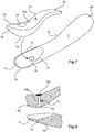
- Figs. 1 to 5 show a stimulation device according to a first preferred embodiment of the present invention.
- the device comprises an elongated first arm 2 having a proximal end portion 2a, a distal end portion 2b and an elongated middle section 2c between the proximal end portion 2a and the distal end portion 2b, and a second arm 4 having a proximal end portion 4a, a distal end portion 4b and an elongated middle section 4c between the proximal end portion 4a and the distal end portion 4b.
- a first operational mode as shown in figs.
- both the first and second arms 2, 4 are connected with each other at their respective proximal end portion 2a, 4a so as to form an essentially V-shaped arrangement wherein the first and second arms 2, 4 are oriented essentially in the same direction and the distal end portions 2b, 4b of the arms 2, 4 are spaced from each other.
- both the arms 2, 4 can alternatively be formed and/or the connection of the arms 2, 4 at their respective proximal end portion 2a, 4a can alternatively be provided so as to form any other arrangement, provided the distal end portions 2b, 4b of the arms 2, 4 are spaced from each other, e.g. like an essentially U-shaped arrangement.
- the device can be used like a conventional "rabbit" stimulator with the first arm 2 at its distal end portion 2b to be inserted into the vagina and the second arm 4 to be brought into contact or touch outside with the skin of a portion of a female human body, in particular in the region of the clitoris or directly with said organ for stimulation. Therefore, the first arm 2 can also be called “inner” arm, and the second arm 4 can also be called “outer” arm.
- the first arm 2 comprises a slightly curved shape wherein the curvature is oriented towards the second arm 4 in the aforementioned fist operational mode, which is advantageous for smoother insertion into the vagina and for the achievement of extra stimulation.
- the second arm 4 comprises a slight S-shape wherein the curvature of its distal end portion 4b is slightly oriented to the first arm 2 in the aforementioned fist operational mode, which results in more convenience to achieve optimal pleasure.
- the length of the second arm 4 is shorter than the length of the first arm 2.
- the distal end portion 4b of the second arm 4 is flexible so that the distance of the distal end portion 4b of the second arm 4 to the first arm 2 is variable.
- the surface of the first arm 2 and/or the second arm 4 at least partly comprises soft silicone material.
- connection of the first and second arms 2, 4 is releasable so that in the disconnected state the first arm 2 and the second arm 4 each are provided as separate individual stimulation devices. Consequently, in addition to the first operational mode according to the figs. 1 and 2 , there is a second operational mode which is shown in figs. 3 and 4 , wherein the device is divided into two separate individual stimulation devices each formed by one of the first and second arms 2, 4.
- the first arm can be used as a conventional dildo to be inserted into a sexual organ
- the second arm 4 can be used as lay-on stimulator to be brought into contact or touch or to be laid upon the skin of a certain portion of a human body for stimulation.
- the coupling means comprises two fingers 6 which form the proximal end portion 2a of the first arm 2 and are surrounded by an edge 7 which defines a boundary for the fingers 6.
- both the fingers 6 are spaced from each other so that an open cavity 8 is provided between inner surfaces 6a of the fingers 6.
- the free end 6b of each finger 6 comprises a smooth nosed protrusion facing the other finger 6 whereby the entrance of the cavity 8 between the free ends 6b of the fingers 6 is slightly restricted.
- the coupling means further comprises an engaging portion 10 provided at the proximal end portion 4a of the second arm 4.
- the shape of the engaging portion 10 is essentially complimentary with regard to the shape of the cavity 8.
- the proximal end portion 4a of the second arm 4 comprises an edge 11 which has essentially a U-shape and surrounds the engaging portion 10 so that the open end of the "U” is essentially oriented towards the distal end portion 4b of the second arm 4. Due to its complementary shape, the engaging portion 10 at the proximal end portion 4a of the second arm 4 is adapted to be accommodated within the cavity 8 between the two fingers 6 of the proximal end portion 2a of the first arm 2.
- the engaging portion 10 at the proximal end portion 4a of the second finger 4 comprises a corresponding concave recess for accommodating said protrusion of the finger 6 so that a face section 10a of the engaging portion 10 facing the first arm 2 in the connected state and the first operation mode is wider than the remaining engaging portion 10.
- the fingers 6 of the first arm 2 are elastic, in particular by being made of elastic material.
- the engaging portion 10 at the proximal end portion 4a of the second arm 4 can be made of elastic material at least at its surface.
- the fingers 6 with its convex inner surface 6a fit with the concave engaging portion 10 wherein the edge 7 surrounding the fingers 6 and the edge 11 surrounding the engaging portion 10 are essentially in contact with each other.
- the fingers 6 can be brought into tight engagement with the engaging portion 10 so as to obtain a fix connection between the first arm 2 and the second arm 4.
- the coupling means according to the above described embodiment operates like a snap-lock allowing a quick connection and a quick release.
- the first arm 2 includes a first vibration means 20 and the second arm 4 includes a second vibration means 22, as schematically shown in fig. 5 .
- the first vibration means 20 is arranged within the distal end portion 2b of the first arm 2 and preferably comprises a rotation ball head driven by a rotation motor (not shown) in order to subject the distal end portion 2b of the first arm 2 not only to vibrations but also to a rotational movement for maximal stimulation.
- the vibration means 20 may be further adapted to subject the elongated middle section 2c of the first arm to vibrations for a stimulation of the vaginal canal or lips; alternatively, for this purpose a further separate vibration means may be arranged within the first arm 2 and in particular its elongated middle section 2c.
- the vibration means 22 is located within the distal end portion 4b of the second arm 4 and provided as a vibration motor in order to create vibrations subject to the distal end portion 4b of the second arm 4 for an intensive feeling of clitoral pleasure.
- the second arm 4 further includes a battery 24 which is arranged essentially in the region of the proximal end portion 4a.
- the first arm 2 does not include a battery, but the vibration means 20 is supplied with electrical power from the battery 24 in the second arm 4 via electrical connectors 26, 27. As shown in figs.
- a first electrical connector 26 is provided at the face section 10a of the engaging portion 10 of the second arm 4 facing the first arm 2 (cf. fig. 3 ), and the second electrical connector 27 is arranged at a distal portion of the inner surface of the cavity 8 (cf. fig. 4 ).
- the electrical connectors 26, 27 are provided and located so that they are in electrical contact with each other when the first and second arms 2, 4 are mechanically connected with each other by means of the above described coupling means.
- buttons 28, 29 are arranged, in the embodiment shown figs. 1 to 5 , at an outer side of the proximal end portion 4a of the second arm 4, wherein the first button 28 is a program button for selecting a certain vibration program and the second button 29 is an intensity button for adjusting the intensity of the vibrations.
- the proximal end portion 4a of the second arm 4 is preferably used as a handle portion.
- a further electrical connector 30 is provided at the free end of the proximal end portion 4a of the second arm 4.
- Figs. 6 to 8 show a second embodiment of the stimulation device wherein the similar or same elements already included in the first embodiment are denoted with the same reference numerals as in the figs. 1 to 5 .
- the similar or same elements already included in the first embodiment are denoted with the same reference numerals as in the figs. 1 to 5 .
- the distal end portion 4b of the second arm 4 comprises two fingers 4bb spaced from each other so as to look as a pair of "rabbit" ears, as particularly shown in fig. 6 .
- a further more important difference from the first embodiment regards the connection between the first and second arm 2, 4.
- the proximal end portion 2a of the first arm 2 a comprises a concave connecting portion 14 formed like well, depression or hollow
- the proximal end portion 4a of the second arm 4 comprises a convex connecting portion 16 formed like a bulge and adapted to be inserted into the concave connection portion 14 of the first arm 2.
- the shape of the concave connecting portion 14 of the first arm 2 is essentially complementary with regard to the shape of the convex connecting portion 16 of the second arm 4 so as to obtain an optimum fit of the convex connecting portion 16 in the concave connecting portion 14 when the first and second arms 2, 4 are connected to each other in the first operational mode or connecting state as shown in fig. 6 .
- the concave connection portion 14 at the proximal end portion 2a of the first am 2 is surrounded and limited by an endless edge 15 which is positioned close to the surface of the convex connecting portion 16 when the first and second arm 2, 4 are connected which each other in the first operational mode (cf. fig. 6 ).
- the second embodiment according to the figs. 6 to 8 differs from the first embodiment according to the figs. 1 to 5 in the construction of the coupling means which are embodied as a rotational fastening means and in particular a quarter-turn fastener.
- an engaging hole 18 is arranged in the bottom of the concave connecting portion 14 of the proximal end portion 2a of the first arm 2 wherein this engaging hole 18 is provided as a female engaging element.
- the proximal end portion of the second arm 4 includes coupling element 19 comprising a knob 19a at the outer surface of the second arm 4, a stem 19b extending through the second arm 4 and a male engaging element 19c provided at the surface of the connecting portion 16.
- the knob 19a, the stem 19b and the male engaging element 19c are coupled and cooperate with each other so that, with the convex connecting portion 16 being arranged within the concave connecting portion 14 for connection of the first and second arm 2, 4 with each other, the male engaging element 19c oriented at a first angular position can loosely inserted into and connected with hole 18 and due to pressing of the knob 19a the pressing force is transferred via the stem 19b and changed to a rotational movement so that the male engaging element 19c is turned to a second angular position where the male engaging element 19c is in tight engagement with the hole 18.
- a further pressing of the knob 19a again results in turning the male engaging element 19c in a reverse direction for releasing from the hole 18 in order to disconnect the first and second arms 2, 4 from each other.
- the second embodiment comprises a control button 32 which is located at the outer surface of the proximal end portion 4a of the second arm 4, but is provided as a circular cross rocker switch comprising a central switch element and two pairs of opposite rocker switch elements which are not denoted by reference numerals here, wherein both of the pairs of rocker switch elements are oriented at a right angle relative to each other so as to form a cross, wherein the one pair of rocker switch elements is provided for controlling the operation of the vibration means of the first arm 2 and the other pair of rocker switch elements is provided for controlling the operation of the vibration means of the second arm 4, whereas the central button is provided for selecting and changing programs for both the vibration means.
Landscapes
- Health & Medical Sciences (AREA)
- Animal Behavior & Ethology (AREA)
- Pain & Pain Management (AREA)
- Physical Education & Sports Medicine (AREA)
- Rehabilitation Therapy (AREA)
- Life Sciences & Earth Sciences (AREA)
- Epidemiology (AREA)
- General Health & Medical Sciences (AREA)
- Public Health (AREA)
- Veterinary Medicine (AREA)
- Reproductive Health (AREA)
- Percussion Or Vibration Massage (AREA)
- Electrotherapy Devices (AREA)
Claims (15)
- Stimulationsvorrichtung, umfassend:einen ersten Arm (2), der einen ersten proximalen Endabschnitt (2a) und einen distalen Endabschnitt (2b), der dazu ausgestaltet ist, in eine Vagina eingeführt zu werden, aufweist;einen zweiten Arm (4), der einen proximalen Endabschnitt (4a) und einen distalen Endabschnitt (4b), der dazu ausgestaltet ist, in Kontakt mit einem Körperabschnitt außerhalb der Vagina zu kommen, aufweist, wobei der erste Arm (2) und der zweite Arm (4) dazu bereitgestellt sind, miteinander an deren jeweiligen proximalen Endabschnitten (2a; 4) verbunden zu sein, so dass im Wesentlichen eine U- oder V-förmige Anordnung gebildet wird, undKopplungsmittel (6, 10; 14, 16, 18, 19), dadurch gekennzeichnet, dass die Kopplungsmittel dazu ausgestaltet sind, eine lösbare Verbindung des ersten und des zweiten Arms (2, 4) an deren jeweiligen proximalen Endabschnitten (2a; 4a) bereitzustellen, wobei das Kopplungsmittel zwei Finger (6), die an dem proximalen Endabschnitt (2a) des ersten Arms (2) bereitgestellt sind, und einen Eingriffsabschnitt (10), der an dem proximalen Endabschnitt (4a) des zweiten Arms (4) bereitgestellt ist, umfasst, wobei der Eingriffsabschnitt (10) dazu angepasst ist, innerhalb eines Hohlraums (8) zwischen den beiden Fingern (6) des ersten Arms (2) aufgenommen und mit den Fingern (8) in Eingriff zu sein.
- Vorrichtung nach Anspruch 1, wobei der proximale Endabschnitt (4a) des zweiten Arms (4) als Handhabungsabschnitt bereitgestellt ist.
- Vorrichtung nach Anspruch 1 oder 2, wobei der distale Endabschnitt (4b) des zweiten Arms (4) wenigstens zwei Finger (4bb) umfasst, die voneinander beabstandet sind und im Wesentlichen nebeneinander angeordnet sind.
- Vorrichtung nach wenigstens einem der vorhergehenden Ansprüche, wobei der erste Arm (2) eine gekrümmte Form umfasst, wobei sich die Krümmung in Richtung des zweiten Arms (4) ausrichtet, wenn der erste und der zweite Arm (2, 4) miteinander über das Kopplungsmittel (6, 10; 14, 16, 18, 19) verbunden sind.
- Vorrichtung nach wenigstens einem der vorhergehenden Ansprüche, wobei der distale Endabschnitt (4b) des zweiten Arms (4) eine gekrümmte Form umfasst, wobei sich die Krümmung zum ersten Arm (2) ausrichtet, wenn der erste und der zweite Arm (2, 4) miteinander über das Kopplungsmittel (6, 10; 14, 16, 18, 19) verbunden sind.
- Vorrichtung nach Anspruch 5, wobei der zweite Arm (4) eine S-Form aufweist.
- Vorrichtung nach wenigstens einem der vorhergehenden Ansprüche, wobei der distale Endabschnitt (4b) des zweiten Arms (4) flexibel ist, so dass der Abstand des distalen Endabschnitts (4b) des zweiten Arms (4) zum ersten Arm (2) variabel ist.
- Vorrichtung nach wenigstens einem der vorhergehenden Ansprüche, wobei der zweite Arm (4) ein Vibrationsmittel (22) umfasst, das dazu angepasst ist, Vibrationen an eine Außenfläche des zweiten Arms (4) zu übertragen.
- Vorrichtung nach Anspruch 9, wobei der zweite Arm eine Batterie (24) zum Zuführen von elektrischer Leistung an das Vibrationsmittel (22) umfasst, und der proximale Endabschnitt (4a) des zweiten Arms (4) einen elektrischen Steckverbinder (30) für Verbindung mit einem elektrischen Kabel zum Laden der Batterie (24) umfasst.
- Vorrichtung nach wenigstens einem der vorhergehenden Ansprüche, wobei der erste Arm (2) ein Antriebsmittel (20) umfasst, das dazu angepasst ist, Vibrationen an eine Außenfläche des ersten Arms (2) zu übertragen und/oder Rotationsbewegungen auf den distalen Endabschnitt (2b) des ersten Arms (2) auszuüben.
- Vorrichtung nach einem der Ansprüche 10 und 12, wobei das Kopplungsmittel ein elektrisches Verbindungsmittel (26, 27) umfasst, das dazu angepasst ist, eine elektrische Verbindung bereitzustellen, wenn der erste und der zweite Arm (2, 4) miteinander an ihren jeweiligen proximalen Endabschnitten (2a; 4a) verbunden sind, so dass dem Antriebsmittel (20) des ersten Arms (2) elektrische Leistung zugeführt wird.
- Vorrichtung nach Anspruch 13, wobei der zweite Arm (4) ein Steuermittel umfasst, das dazu angepasst ist, den Betrieb des Vibrationsmittels (22) des zweiten Arms (4) zu steuern, und, wenn der erste Arm (2) mit dem zweiten Arm (4) über das Kopplungsmittel verbunden ist, das Antriebsmittel (20) des ersten Arms (2) zu steuern, wobei das Steuermittel einen Steuerknopf (28, 29; 32) umfasst, der an der Außenfläche des proximalen Endabschnitts (4a) des zweiten Arms (4) vorgesehen ist.
- Vorrichtung nach Anspruch 14, wobei der Steuerknopf (32) als Wippschalter bereitgestellt ist.
- Vorrichtung nach einem der vorhergehenden Ansprüche, wobei wenigstens einer der Finger (6) eine gekrümmte Form nahe seinem freien Ende (6b) oder an seinem freien Ende (6b) umfasst, so dass ein Vorsprung mit glatter Nase gebildet wird, der dem anderen Finger (6) zugewandt ist, und wobei der Eingriffsabschnitt (10) des zweiten Arms (4) eine konkave Ausnehmung zum Aufnehmen und Eingreifen in den Vorsprung des Fingers (6) umfasst.
- Vorrichtung nach wenigstens einem der vorhergehenden Ansprüche, wobei die Oberfläche des ersten Arms (2) und/oder des zweiten Arms (4) wenigstens teilweise weiches Silikonmaterial umfasst.
Applications Claiming Priority (1)
| Application Number | Priority Date | Filing Date | Title |
|---|---|---|---|
| PCT/EP2012/067466 WO2014037048A1 (en) | 2012-09-07 | 2012-09-07 | Stimulation device |
Publications (2)
| Publication Number | Publication Date |
|---|---|
| EP2892494A1 EP2892494A1 (de) | 2015-07-15 |
| EP2892494B1 true EP2892494B1 (de) | 2019-08-28 |
Family
ID=46800210
Family Applications (1)
| Application Number | Title | Priority Date | Filing Date |
|---|---|---|---|
| EP12756010.0A Not-in-force EP2892494B1 (de) | 2012-09-07 | 2012-09-07 | Stimulationsvorrichtung |
Country Status (4)
| Country | Link |
|---|---|
| US (1) | US9968512B2 (de) |
| EP (1) | EP2892494B1 (de) |
| HK (1) | HK1212201A1 (de) |
| WO (1) | WO2014037048A1 (de) |
Families Citing this family (18)
| Publication number | Priority date | Publication date | Assignee | Title |
|---|---|---|---|---|
| US20150157531A1 (en) * | 2013-12-09 | 2015-06-11 | Filip Sedic | Sexual intercourse massage device |
| USD874675S1 (en) * | 2016-12-02 | 2020-02-04 | Brandcore Limited | Vibrator |
| WO2018167611A1 (en) * | 2017-03-15 | 2018-09-20 | Schoon Darryl | Pleasure clasp device |
| RU2017126944A (ru) * | 2017-07-27 | 2019-01-28 | Сергей Евгеньевич ТОПОЛЕВ | Устройство для массажа с разгибающимся элементом (варианты), способ его изготовления и способ его применения |
| JP1643588S (de) * | 2018-12-07 | 2019-10-21 | ||
| CN109549832B (zh) * | 2018-12-29 | 2023-12-19 | 东莞市谦禾电子科技有限公司 | 按摩装置 |
| USD882108S1 (en) * | 2019-11-21 | 2020-04-21 | Yingzhong Li | Sex toy |
| CN111012649A (zh) * | 2019-12-06 | 2020-04-17 | 乐爱健康科技(苏州)有限公司 | 一种按摩装置 |
| US20230346634A1 (en) * | 2022-04-27 | 2023-11-02 | Guangzhou Pinai Technology Co., Ltd. | Massager |
| US20220370287A1 (en) * | 2022-06-09 | 2022-11-24 | Shenzhen Alltokee Technology Co., Ltd | Massage device with replaceable structure |
| USD1016314S1 (en) * | 2022-09-22 | 2024-02-27 | Dongguan Jindouyun Silicone Electronics Co., Ltd. | Vibration massager |
| USD1016316S1 (en) * | 2022-09-29 | 2024-02-27 | Dongguan Jindouyun Silicone Electronics Co., Ltd. | Vibration massager |
| CN116115479A (zh) * | 2022-12-23 | 2023-05-16 | 深圳市司沃康科技有限公司 | 多功能按摩器 |
| US11771619B1 (en) * | 2023-01-17 | 2023-10-03 | Bo Yan | Massage device |
| USD1034987S1 (en) * | 2023-03-07 | 2024-07-09 | Yunkai Sui | Penis ring |
| US12201573B2 (en) * | 2023-03-08 | 2025-01-21 | Bo Yan | Massage device |
| US12201574B2 (en) | 2023-03-08 | 2025-01-21 | Dongguan Qunan Technology Co., Ltd. | Massage device |
| US12127993B1 (en) * | 2024-02-29 | 2024-10-29 | Kun Peng | Massager |
Family Cites Families (10)
| Publication number | Priority date | Publication date | Assignee | Title |
|---|---|---|---|---|
| US20020188233A1 (en) * | 2001-06-08 | 2002-12-12 | Denyes Judson L. | Stimulation device |
| JP2004313690A (ja) | 2003-04-15 | 2004-11-11 | Nippori Gift:Kk | 性感帯刺激具 |
| EP1477149B1 (de) | 2003-05-14 | 2009-07-22 | Rocks off Limited | Stimulationshilfe |
| JP2005288079A (ja) | 2004-03-31 | 2005-10-20 | Nippori Gift:Kk | 性感帯開発鍛練具 |
| CA2491249A1 (en) * | 2004-12-17 | 2006-06-17 | Bruce Murison | Electro-mechanical sexual stimulation device |
| US7717867B2 (en) * | 2006-10-16 | 2010-05-18 | Nanma Manufacturing, Co., Ltd. | Massage apparatus with positional set-up actuator |
| DE202009012229U1 (de) | 2009-06-04 | 2009-11-19 | Hintze, Andreas Angelo | Massagevorrichtung |
| WO2011045588A1 (en) | 2009-10-13 | 2011-04-21 | Sas Capital Investments Limited | Device including a hnmdle assembly for use with a sex toy |
| US8308667B2 (en) | 2010-03-12 | 2012-11-13 | Wing Pow International Corp. | Interactive massaging device |
| EP2582430B1 (de) * | 2010-06-17 | 2019-03-13 | Incontrol Medical, LLC | Vorrichtung für harninkontinenz |
-
2012
- 2012-09-07 EP EP12756010.0A patent/EP2892494B1/de not_active Not-in-force
- 2012-09-07 HK HK16100421.1A patent/HK1212201A1/xx unknown
- 2012-09-07 US US14/426,319 patent/US9968512B2/en not_active Expired - Fee Related
- 2012-09-07 WO PCT/EP2012/067466 patent/WO2014037048A1/en not_active Ceased
Non-Patent Citations (1)
| Title |
|---|
| None * |
Also Published As
| Publication number | Publication date |
|---|---|
| US9968512B2 (en) | 2018-05-15 |
| EP2892494A1 (de) | 2015-07-15 |
| HK1212201A1 (en) | 2016-06-10 |
| US20160184178A1 (en) | 2016-06-30 |
| WO2014037048A1 (en) | 2014-03-13 |
Similar Documents
| Publication | Publication Date | Title |
|---|---|---|
| EP2892494B1 (de) | Stimulationsvorrichtung | |
| EP2892493B1 (de) | Stimulationsvorrichtung | |
| AU2007295951B2 (en) | Sexual stimulation apparatus | |
| CN101080210B (zh) | 机电性刺激装置 | |
| US6748604B2 (en) | Glove massager | |
| ES2905216T3 (es) | Dispositivo combinado de estimulación sexual interna y externa | |
| CN102711708A (zh) | 具有柔性底层结构的按摩装置 | |
| US9138373B2 (en) | Massage device | |
| JP7337355B2 (ja) | 圧力部を備えるマッサージ器具、この器具を使用する方法、及びこの器具の製造方法 | |
| CN104144669A (zh) | 用于关节连接部的振动组合件 | |
| US9649250B2 (en) | Personal massager | |
| US9717643B2 (en) | Vibrator | |
| WO2014008606A1 (en) | G-spot and clitoral stimulation device | |
| CN221470326U (zh) | 按摩装置 | |
| US20250241823A1 (en) | Easy-to-use massager | |
| RU180156U1 (ru) | Устройство для массажа с округлым элементом | |
| US20080269553A1 (en) | Powered massager for internal use on the human body | |
| WO2018021946A1 (ru) | Устройство для массажа с округлым элементом, способ его применения и способ его изготовления | |
| WO2019177499A1 (ru) | Устройство для массажа, способ его использования и способ его изготовления | |
| ES1312502U (es) | Guante electronico para la estimulacion sexual | |
| HK1212200B (en) | Stimulation device | |
| KR200366705Y1 (ko) | 이어폰형 귀 경혈 자극기 | |
| KR200407485Y1 (ko) | 손가락 자극기 | |
| US20200107986A1 (en) | Device for sexual stimulation | |
| CN2933391Y (zh) | 一种手持振动按摩器 |
Legal Events
| Date | Code | Title | Description |
|---|---|---|---|
| PUAI | Public reference made under article 153(3) epc to a published international application that has entered the european phase |
Free format text: ORIGINAL CODE: 0009012 |
|
| 17P | Request for examination filed |
Effective date: 20150407 |
|
| AK | Designated contracting states |
Kind code of ref document: A1 Designated state(s): AL AT BE BG CH CY CZ DE DK EE ES FI FR GB GR HR HU IE IS IT LI LT LU LV MC MK MT NL NO PL PT RO RS SE SI SK SM TR |
|
| AX | Request for extension of the european patent |
Extension state: BA ME |
|
| DAX | Request for extension of the european patent (deleted) | ||
| REG | Reference to a national code |
Ref country code: HK Ref legal event code: DE Ref document number: 1212201 Country of ref document: HK |
|
| STAA | Information on the status of an ep patent application or granted ep patent |
Free format text: STATUS: EXAMINATION IS IN PROGRESS |
|
| 17Q | First examination report despatched |
Effective date: 20180509 |
|
| GRAP | Despatch of communication of intention to grant a patent |
Free format text: ORIGINAL CODE: EPIDOSNIGR1 |
|
| STAA | Information on the status of an ep patent application or granted ep patent |
Free format text: STATUS: GRANT OF PATENT IS INTENDED |
|
| INTG | Intention to grant announced |
Effective date: 20190313 |
|
| GRAS | Grant fee paid |
Free format text: ORIGINAL CODE: EPIDOSNIGR3 |
|
| GRAA | (expected) grant |
Free format text: ORIGINAL CODE: 0009210 |
|
| STAA | Information on the status of an ep patent application or granted ep patent |
Free format text: STATUS: THE PATENT HAS BEEN GRANTED |
|
| AK | Designated contracting states |
Kind code of ref document: B1 Designated state(s): AL AT BE BG CH CY CZ DE DK EE ES FI FR GB GR HR HU IE IS IT LI LT LU LV MC MK MT NL NO PL PT RO RS SE SI SK SM TR |
|
| REG | Reference to a national code |
Ref country code: GB Ref legal event code: FG4D |
|
| REG | Reference to a national code |
Ref country code: CH Ref legal event code: EP |
|
| REG | Reference to a national code |
Ref country code: DE Ref legal event code: R096 Ref document number: 602012063387 Country of ref document: DE |
|
| REG | Reference to a national code |
Ref country code: AT Ref legal event code: REF Ref document number: 1171462 Country of ref document: AT Kind code of ref document: T Effective date: 20190915 |
|
| REG | Reference to a national code |
Ref country code: IE Ref legal event code: FG4D |
|
| REG | Reference to a national code |
Ref country code: NL Ref legal event code: FP |
|
| REG | Reference to a national code |
Ref country code: LT Ref legal event code: MG4D |
|
| PG25 | Lapsed in a contracting state [announced via postgrant information from national office to epo] |
Ref country code: BG Free format text: LAPSE BECAUSE OF FAILURE TO SUBMIT A TRANSLATION OF THE DESCRIPTION OR TO PAY THE FEE WITHIN THE PRESCRIBED TIME-LIMIT Effective date: 20191128 Ref country code: NO Free format text: LAPSE BECAUSE OF FAILURE TO SUBMIT A TRANSLATION OF THE DESCRIPTION OR TO PAY THE FEE WITHIN THE PRESCRIBED TIME-LIMIT Effective date: 20191128 Ref country code: PT Free format text: LAPSE BECAUSE OF FAILURE TO SUBMIT A TRANSLATION OF THE DESCRIPTION OR TO PAY THE FEE WITHIN THE PRESCRIBED TIME-LIMIT Effective date: 20191230 Ref country code: LT Free format text: LAPSE BECAUSE OF FAILURE TO SUBMIT A TRANSLATION OF THE DESCRIPTION OR TO PAY THE FEE WITHIN THE PRESCRIBED TIME-LIMIT Effective date: 20190828 Ref country code: FI Free format text: LAPSE BECAUSE OF FAILURE TO SUBMIT A TRANSLATION OF THE DESCRIPTION OR TO PAY THE FEE WITHIN THE PRESCRIBED TIME-LIMIT Effective date: 20190828 Ref country code: SE Free format text: LAPSE BECAUSE OF FAILURE TO SUBMIT A TRANSLATION OF THE DESCRIPTION OR TO PAY THE FEE WITHIN THE PRESCRIBED TIME-LIMIT Effective date: 20190828 Ref country code: HR Free format text: LAPSE BECAUSE OF FAILURE TO SUBMIT A TRANSLATION OF THE DESCRIPTION OR TO PAY THE FEE WITHIN THE PRESCRIBED TIME-LIMIT Effective date: 20190828 |
|
| PG25 | Lapsed in a contracting state [announced via postgrant information from national office to epo] |
Ref country code: LV Free format text: LAPSE BECAUSE OF FAILURE TO SUBMIT A TRANSLATION OF THE DESCRIPTION OR TO PAY THE FEE WITHIN THE PRESCRIBED TIME-LIMIT Effective date: 20190828 Ref country code: GR Free format text: LAPSE BECAUSE OF FAILURE TO SUBMIT A TRANSLATION OF THE DESCRIPTION OR TO PAY THE FEE WITHIN THE PRESCRIBED TIME-LIMIT Effective date: 20191129 Ref country code: RS Free format text: LAPSE BECAUSE OF FAILURE TO SUBMIT A TRANSLATION OF THE DESCRIPTION OR TO PAY THE FEE WITHIN THE PRESCRIBED TIME-LIMIT Effective date: 20190828 Ref country code: AL Free format text: LAPSE BECAUSE OF FAILURE TO SUBMIT A TRANSLATION OF THE DESCRIPTION OR TO PAY THE FEE WITHIN THE PRESCRIBED TIME-LIMIT Effective date: 20190828 Ref country code: IS Free format text: LAPSE BECAUSE OF FAILURE TO SUBMIT A TRANSLATION OF THE DESCRIPTION OR TO PAY THE FEE WITHIN THE PRESCRIBED TIME-LIMIT Effective date: 20191228 Ref country code: ES Free format text: LAPSE BECAUSE OF FAILURE TO SUBMIT A TRANSLATION OF THE DESCRIPTION OR TO PAY THE FEE WITHIN THE PRESCRIBED TIME-LIMIT Effective date: 20190828 |
|
| REG | Reference to a national code |
Ref country code: AT Ref legal event code: MK05 Ref document number: 1171462 Country of ref document: AT Kind code of ref document: T Effective date: 20190828 |
|
| PG25 | Lapsed in a contracting state [announced via postgrant information from national office to epo] |
Ref country code: TR Free format text: LAPSE BECAUSE OF FAILURE TO SUBMIT A TRANSLATION OF THE DESCRIPTION OR TO PAY THE FEE WITHIN THE PRESCRIBED TIME-LIMIT Effective date: 20190828 |
|
| REG | Reference to a national code |
Ref country code: DE Ref legal event code: R119 Ref document number: 602012063387 Country of ref document: DE |
|
| PG25 | Lapsed in a contracting state [announced via postgrant information from national office to epo] |
Ref country code: IT Free format text: LAPSE BECAUSE OF FAILURE TO SUBMIT A TRANSLATION OF THE DESCRIPTION OR TO PAY THE FEE WITHIN THE PRESCRIBED TIME-LIMIT Effective date: 20190828 Ref country code: AT Free format text: LAPSE BECAUSE OF FAILURE TO SUBMIT A TRANSLATION OF THE DESCRIPTION OR TO PAY THE FEE WITHIN THE PRESCRIBED TIME-LIMIT Effective date: 20190828 Ref country code: EE Free format text: LAPSE BECAUSE OF FAILURE TO SUBMIT A TRANSLATION OF THE DESCRIPTION OR TO PAY THE FEE WITHIN THE PRESCRIBED TIME-LIMIT Effective date: 20190828 Ref country code: PL Free format text: LAPSE BECAUSE OF FAILURE TO SUBMIT A TRANSLATION OF THE DESCRIPTION OR TO PAY THE FEE WITHIN THE PRESCRIBED TIME-LIMIT Effective date: 20190828 Ref country code: DK Free format text: LAPSE BECAUSE OF FAILURE TO SUBMIT A TRANSLATION OF THE DESCRIPTION OR TO PAY THE FEE WITHIN THE PRESCRIBED TIME-LIMIT Effective date: 20190828 Ref country code: RO Free format text: LAPSE BECAUSE OF FAILURE TO SUBMIT A TRANSLATION OF THE DESCRIPTION OR TO PAY THE FEE WITHIN THE PRESCRIBED TIME-LIMIT Effective date: 20190828 |
|
| REG | Reference to a national code |
Ref country code: NL Ref legal event code: MM Effective date: 20191001 |
|
| PG25 | Lapsed in a contracting state [announced via postgrant information from national office to epo] |
Ref country code: MC Free format text: LAPSE BECAUSE OF FAILURE TO SUBMIT A TRANSLATION OF THE DESCRIPTION OR TO PAY THE FEE WITHIN THE PRESCRIBED TIME-LIMIT Effective date: 20190828 Ref country code: CZ Free format text: LAPSE BECAUSE OF FAILURE TO SUBMIT A TRANSLATION OF THE DESCRIPTION OR TO PAY THE FEE WITHIN THE PRESCRIBED TIME-LIMIT Effective date: 20190828 Ref country code: SM Free format text: LAPSE BECAUSE OF FAILURE TO SUBMIT A TRANSLATION OF THE DESCRIPTION OR TO PAY THE FEE WITHIN THE PRESCRIBED TIME-LIMIT Effective date: 20190828 Ref country code: IS Free format text: LAPSE BECAUSE OF FAILURE TO SUBMIT A TRANSLATION OF THE DESCRIPTION OR TO PAY THE FEE WITHIN THE PRESCRIBED TIME-LIMIT Effective date: 20200224 Ref country code: SK Free format text: LAPSE BECAUSE OF FAILURE TO SUBMIT A TRANSLATION OF THE DESCRIPTION OR TO PAY THE FEE WITHIN THE PRESCRIBED TIME-LIMIT Effective date: 20190828 |
|
| REG | Reference to a national code |
Ref country code: CH Ref legal event code: PL |
|
| PLBE | No opposition filed within time limit |
Free format text: ORIGINAL CODE: 0009261 |
|
| STAA | Information on the status of an ep patent application or granted ep patent |
Free format text: STATUS: NO OPPOSITION FILED WITHIN TIME LIMIT |
|
| PG2D | Information on lapse in contracting state deleted |
Ref country code: IS |
|
| PG25 | Lapsed in a contracting state [announced via postgrant information from national office to epo] |
Ref country code: CH Free format text: LAPSE BECAUSE OF NON-PAYMENT OF DUE FEES Effective date: 20190930 Ref country code: LU Free format text: LAPSE BECAUSE OF NON-PAYMENT OF DUE FEES Effective date: 20190907 Ref country code: NL Free format text: LAPSE BECAUSE OF NON-PAYMENT OF DUE FEES Effective date: 20191001 Ref country code: IE Free format text: LAPSE BECAUSE OF NON-PAYMENT OF DUE FEES Effective date: 20190907 Ref country code: LI Free format text: LAPSE BECAUSE OF NON-PAYMENT OF DUE FEES Effective date: 20190930 Ref country code: DE Free format text: LAPSE BECAUSE OF NON-PAYMENT OF DUE FEES Effective date: 20200401 |
|
| 26N | No opposition filed |
Effective date: 20200603 |
|
| REG | Reference to a national code |
Ref country code: BE Ref legal event code: MM Effective date: 20190930 |
|
| PG25 | Lapsed in a contracting state [announced via postgrant information from national office to epo] |
Ref country code: SI Free format text: LAPSE BECAUSE OF FAILURE TO SUBMIT A TRANSLATION OF THE DESCRIPTION OR TO PAY THE FEE WITHIN THE PRESCRIBED TIME-LIMIT Effective date: 20190828 Ref country code: BE Free format text: LAPSE BECAUSE OF NON-PAYMENT OF DUE FEES Effective date: 20190930 |
|
| GBPC | Gb: european patent ceased through non-payment of renewal fee |
Effective date: 20191128 |
|
| PG25 | Lapsed in a contracting state [announced via postgrant information from national office to epo] |
Ref country code: FR Free format text: LAPSE BECAUSE OF NON-PAYMENT OF DUE FEES Effective date: 20191028 Ref country code: GB Free format text: LAPSE BECAUSE OF NON-PAYMENT OF DUE FEES Effective date: 20191128 |
|
| PG25 | Lapsed in a contracting state [announced via postgrant information from national office to epo] |
Ref country code: CY Free format text: LAPSE BECAUSE OF FAILURE TO SUBMIT A TRANSLATION OF THE DESCRIPTION OR TO PAY THE FEE WITHIN THE PRESCRIBED TIME-LIMIT Effective date: 20190828 |
|
| PG25 | Lapsed in a contracting state [announced via postgrant information from national office to epo] |
Ref country code: HU Free format text: LAPSE BECAUSE OF FAILURE TO SUBMIT A TRANSLATION OF THE DESCRIPTION OR TO PAY THE FEE WITHIN THE PRESCRIBED TIME-LIMIT; INVALID AB INITIO Effective date: 20120907 Ref country code: MT Free format text: LAPSE BECAUSE OF FAILURE TO SUBMIT A TRANSLATION OF THE DESCRIPTION OR TO PAY THE FEE WITHIN THE PRESCRIBED TIME-LIMIT Effective date: 20190828 |
|
| REG | Reference to a national code |
Ref country code: HK Ref legal event code: WD Ref document number: 1212201 Country of ref document: HK |
|
| PG25 | Lapsed in a contracting state [announced via postgrant information from national office to epo] |
Ref country code: MK Free format text: LAPSE BECAUSE OF FAILURE TO SUBMIT A TRANSLATION OF THE DESCRIPTION OR TO PAY THE FEE WITHIN THE PRESCRIBED TIME-LIMIT Effective date: 20190828 |