EP4403137A1 - System zur befestigung eines herzklappenventils an einer herzprothese und herzprothese mit einem solchen befestigungssystem. - Google Patents
System zur befestigung eines herzklappenventils an einer herzprothese und herzprothese mit einem solchen befestigungssystem. Download PDFInfo
- Publication number
- EP4403137A1 EP4403137A1 EP23197327.2A EP23197327A EP4403137A1 EP 4403137 A1 EP4403137 A1 EP 4403137A1 EP 23197327 A EP23197327 A EP 23197327A EP 4403137 A1 EP4403137 A1 EP 4403137A1
- Authority
- EP
- European Patent Office
- Prior art keywords
- pins
- heart valve
- prosthesis
- heart
- cardiac prosthesis
- Prior art date
- Legal status (The legal status is an assumption and is not a legal conclusion. Google has not performed a legal analysis and makes no representation as to the accuracy of the status listed.)
- Pending
Links
Images


Classifications
-
- A—HUMAN NECESSITIES
- A61—MEDICAL OR VETERINARY SCIENCE; HYGIENE
- A61F—FILTERS IMPLANTABLE INTO BLOOD VESSELS; PROSTHESES; DEVICES PROVIDING PATENCY TO, OR PREVENTING COLLAPSING OF, TUBULAR STRUCTURES OF THE BODY, e.g. STENTS; ORTHOPAEDIC, NURSING OR CONTRACEPTIVE DEVICES; FOMENTATION; TREATMENT OR PROTECTION OF EYES OR EARS; BANDAGES, DRESSINGS OR ABSORBENT PADS; FIRST-AID KITS
- A61F2/00—Filters implantable into blood vessels; Prostheses, i.e. artificial substitutes or replacements for parts of the body; Appliances for connecting them with the body; Devices providing patency to, or preventing collapsing of, tubular structures of the body, e.g. stents
- A61F2/02—Prostheses implantable into the body
- A61F2/24—Heart valves ; Vascular valves, e.g. venous valves; Heart implants, e.g. passive devices for improving the function of the native valve or the heart muscle; Transmyocardial revascularisation [TMR] devices; Valves implantable in the body
- A61F2/2409—Support rings therefor, e.g. for connecting valves to tissue
-
- A—HUMAN NECESSITIES
- A61—MEDICAL OR VETERINARY SCIENCE; HYGIENE
- A61F—FILTERS IMPLANTABLE INTO BLOOD VESSELS; PROSTHESES; DEVICES PROVIDING PATENCY TO, OR PREVENTING COLLAPSING OF, TUBULAR STRUCTURES OF THE BODY, e.g. STENTS; ORTHOPAEDIC, NURSING OR CONTRACEPTIVE DEVICES; FOMENTATION; TREATMENT OR PROTECTION OF EYES OR EARS; BANDAGES, DRESSINGS OR ABSORBENT PADS; FIRST-AID KITS
- A61F2/00—Filters implantable into blood vessels; Prostheses, i.e. artificial substitutes or replacements for parts of the body; Appliances for connecting them with the body; Devices providing patency to, or preventing collapsing of, tubular structures of the body, e.g. stents
- A61F2/02—Prostheses implantable into the body
- A61F2/24—Heart valves ; Vascular valves, e.g. venous valves; Heart implants, e.g. passive devices for improving the function of the native valve or the heart muscle; Transmyocardial revascularisation [TMR] devices; Valves implantable in the body
- A61F2/2412—Heart valves ; Vascular valves, e.g. venous valves; Heart implants, e.g. passive devices for improving the function of the native valve or the heart muscle; Transmyocardial revascularisation [TMR] devices; Valves implantable in the body with soft flexible valve members, e.g. tissue valves shaped like natural valves
-
- A—HUMAN NECESSITIES
- A61—MEDICAL OR VETERINARY SCIENCE; HYGIENE
- A61F—FILTERS IMPLANTABLE INTO BLOOD VESSELS; PROSTHESES; DEVICES PROVIDING PATENCY TO, OR PREVENTING COLLAPSING OF, TUBULAR STRUCTURES OF THE BODY, e.g. STENTS; ORTHOPAEDIC, NURSING OR CONTRACEPTIVE DEVICES; FOMENTATION; TREATMENT OR PROTECTION OF EYES OR EARS; BANDAGES, DRESSINGS OR ABSORBENT PADS; FIRST-AID KITS
- A61F2/00—Filters implantable into blood vessels; Prostheses, i.e. artificial substitutes or replacements for parts of the body; Appliances for connecting them with the body; Devices providing patency to, or preventing collapsing of, tubular structures of the body, e.g. stents
- A61F2/02—Prostheses implantable into the body
- A61F2/24—Heart valves ; Vascular valves, e.g. venous valves; Heart implants, e.g. passive devices for improving the function of the native valve or the heart muscle; Transmyocardial revascularisation [TMR] devices; Valves implantable in the body
- A61F2/2412—Heart valves ; Vascular valves, e.g. venous valves; Heart implants, e.g. passive devices for improving the function of the native valve or the heart muscle; Transmyocardial revascularisation [TMR] devices; Valves implantable in the body with soft flexible valve members, e.g. tissue valves shaped like natural valves
- A61F2/2418—Scaffolds therefor, e.g. support stents
-
- A—HUMAN NECESSITIES
- A61—MEDICAL OR VETERINARY SCIENCE; HYGIENE
- A61M—DEVICES FOR INTRODUCING MEDIA INTO, OR ONTO, THE BODY; DEVICES FOR TRANSDUCING BODY MEDIA OR FOR TAKING MEDIA FROM THE BODY; DEVICES FOR PRODUCING OR ENDING SLEEP OR STUPOR
- A61M60/00—Blood pumps; Devices for mechanical circulatory actuation; Balloon pumps for circulatory assistance
- A61M60/10—Location thereof with respect to the patient's body
- A61M60/122—Implantable pumps or pumping devices, i.e. the blood being pumped inside the patient's body
- A61M60/196—Implantable pumps or pumping devices, i.e. the blood being pumped inside the patient's body replacing the entire heart, e.g. total artificial hearts [TAH]
-
- A—HUMAN NECESSITIES
- A61—MEDICAL OR VETERINARY SCIENCE; HYGIENE
- A61M—DEVICES FOR INTRODUCING MEDIA INTO, OR ONTO, THE BODY; DEVICES FOR TRANSDUCING BODY MEDIA OR FOR TAKING MEDIA FROM THE BODY; DEVICES FOR PRODUCING OR ENDING SLEEP OR STUPOR
- A61M60/00—Blood pumps; Devices for mechanical circulatory actuation; Balloon pumps for circulatory assistance
- A61M60/20—Type thereof
- A61M60/247—Positive displacement blood pumps
- A61M60/253—Positive displacement blood pumps including a displacement member directly acting on the blood
- A61M60/268—Positive displacement blood pumps including a displacement member directly acting on the blood the displacement member being flexible, e.g. membranes, diaphragms or bladders
-
- A—HUMAN NECESSITIES
- A61—MEDICAL OR VETERINARY SCIENCE; HYGIENE
- A61M—DEVICES FOR INTRODUCING MEDIA INTO, OR ONTO, THE BODY; DEVICES FOR TRANSDUCING BODY MEDIA OR FOR TAKING MEDIA FROM THE BODY; DEVICES FOR PRODUCING OR ENDING SLEEP OR STUPOR
- A61M60/00—Blood pumps; Devices for mechanical circulatory actuation; Balloon pumps for circulatory assistance
- A61M60/80—Constructional details other than related to driving
- A61M60/855—Constructional details other than related to driving of implantable pumps or pumping devices
- A61M60/857—Implantable blood tubes
- A61M60/859—Connections therefor
-
- A—HUMAN NECESSITIES
- A61—MEDICAL OR VETERINARY SCIENCE; HYGIENE
- A61M—DEVICES FOR INTRODUCING MEDIA INTO, OR ONTO, THE BODY; DEVICES FOR TRANSDUCING BODY MEDIA OR FOR TAKING MEDIA FROM THE BODY; DEVICES FOR PRODUCING OR ENDING SLEEP OR STUPOR
- A61M60/00—Blood pumps; Devices for mechanical circulatory actuation; Balloon pumps for circulatory assistance
- A61M60/80—Constructional details other than related to driving
- A61M60/855—Constructional details other than related to driving of implantable pumps or pumping devices
- A61M60/89—Valves
- A61M60/894—Passive valves, i.e. valves actuated by the blood
-
- A—HUMAN NECESSITIES
- A61—MEDICAL OR VETERINARY SCIENCE; HYGIENE
- A61M—DEVICES FOR INTRODUCING MEDIA INTO, OR ONTO, THE BODY; DEVICES FOR TRANSDUCING BODY MEDIA OR FOR TAKING MEDIA FROM THE BODY; DEVICES FOR PRODUCING OR ENDING SLEEP OR STUPOR
- A61M60/00—Blood pumps; Devices for mechanical circulatory actuation; Balloon pumps for circulatory assistance
- A61M60/80—Constructional details other than related to driving
- A61M60/855—Constructional details other than related to driving of implantable pumps or pumping devices
- A61M60/89—Valves
- A61M60/894—Passive valves, i.e. valves actuated by the blood
- A61M60/896—Passive valves, i.e. valves actuated by the blood having flexible or resilient parts, e.g. flap valves
Definitions
- the present invention relates to a system for fixing a heart valve to a cardiac prosthesis, said cardiac prosthesis being implantable in the pericardial cavity of a patient and being capable of replacing the natural left and right ventricles of said patient after their ablation.
- the present invention also relates to a cardiac prosthesis provided with such a fixing system.
- a fully implantable cardiac prosthesis as described for example in patents FR-2 784 585 And FR-2 902 345 , has the function of replacing the patient's ventricles while retaining the atria. To do this, it comprises a rigid prosthesis body in which artificial ventricles are arranged.
- this cardiac prosthesis that is to say an artificial heart prosthesis, in the patient's pericardial cavity, it is necessary to create interfaces between the vascular network (atria and arteries) of the patient and the prosthesis. heart while respecting the patient's anatomy.
- the natural heart includes four heart valves which separate the different cavities and ensure good circulation of blood between them, namely two heart valves (mitral valve and tricuspid valve) located between the atria and the ventricles and two heart valves (mitral valve aortic and pulmonary valve) located between the ventricles and the arteries.
- a fully implantable cardiac prosthesis which is intended to replace the natural heart, must therefore integrate (artificial) heart valves in order to recreate this specific connection with the atria and the arteries.
- a usual heart valve In order to be able to use for this purpose usual heart valves, used in the context of valve replacement surgeries, the prosthesis totally implantable cardiac device must integrate a specific interface.
- a usual heart valve generally includes three leaflets which open and close under the action of pressure, three legs to which the leaflets are attached and a base which allows the surgeon to suture the valve.
- the base can be flat or corrugated (wave-shaped).
- Such heart valves can be used for the admission or ejection of blood into the cardiac prosthesis.
- the heart valve is of the flat base type and it rests with its flat base in a channel of the cardiac prosthesis, the legs being oriented towards the outside of the ventricles.
- a fabric conduit is arranged in the channel of the prosthetic heart above the heart valve.
- a locking system locks the assembly onto the cardiac prosthesis, with the fabric conduit then sutured onto the patient's artery by the surgeon.
- the present invention aims to remedy at least some of the aforementioned drawbacks, with the aim of simplifying and improving the operation of fixing artificial heart valves on a cardiac prosthesis (intended to be implanted in the pericardial cavity of a patient in order to replace the patient's natural left and right ventricles), and to be able to use heart valves of various designs and in particular heart valves with non-planar bases.
- it concerns a fixing system intended for fixing an (artificial) heart valve on a heart prosthesis.
- said fixing system comprises a male ring provided with pins, and a cooperating part provided with openings, said male ring or said cooperating part being intended to be secured to the cardiac prosthesis, and the pins and the openings are configured so that said pins pass through a flange of the heart valve and enter said openings in a so-called fixing position.
- the male ring and the cooperating part which are intended to hold the heart valve at the level of the flange can be adapted to this flange, namely to the base of the heart valve, as specified below.
- the fixing system can thus be adapted to heart valves of various designs and in particular heart valves with non-planar bases, and this both for heart valves used for ejection and for heart valves used for admission.
- one of the two elements is intended to be made integral with the cardiac prosthesis.
- the male ring and the cooperating part each have a so-called contact face, these contact faces being intended to grip at least the flange of the heart valve in the fixing position, and said contact faces have suitable shapes to the shape of the heart valve flange.
- the pins and the openings are configured so that the pins are substantially straight in the fixing position.
- the pins and the openings are configured so that the pins are curved (or bent) in the fixing position, for example bent or with a curved shape. This deformation makes it possible to strengthen the hold of the pins in the openings and thus the hold between the different parts linked together.
- the pins can have a constant diameter. However, in a particular embodiment, the pins have a diameter which reduces towards a free end, which makes it easier to maintain the pins in the openings.
- the male ring which comprises at least one annular support and the pins secured to the annular support is a single piece, which makes it easier to produce.
- the pins it is also possible for the pins to be attached to the annular support.
- the cooperating part is a female ring.
- one of these two rings (the male ring or the female ring) is intended to be fixed on the cardiac prosthesis.
- the female ring comprises a face opposite the contact face, which has a shape complementary to a shape of a so-called receiving face of the cardiac prosthesis.
- the cooperating part corresponds to a part of the cardiac prosthesis.
- said part of the cardiac prosthesis comprises a tubular element which is provided, on its internal periphery, with a rim intended to receive the collar of the heart valve.
- the pins and the openings are configured so that said pins also pass through a flange of a conduit (intended to be sutured to an artery) in the fixing position.
- the present invention also relates to a cardiac prosthesis implantable in the pericardial cavity of a patient, said cardiac prosthesis being capable of replacing the natural left and right ventricles of said patient and comprising at least one heart valve.
- the cardiac prosthesis comprises at least one fixing system such as that described above, for fixing the heart valve to the cardiac prosthesis.
- the cardiac prosthesis comprises two, three or (preferably) four heart valves, each of which is fixed to the cardiac prosthesis, using a fixing system such as that described above.
- the fixing system 1 illustrating the invention and represented schematically in different particular embodiments on the figures 1 to 7 has the function of fixing an artificial heart valve (intended to replace a patient's natural heart valve) on a cardiac prosthesis.
- This cardiac prosthesis 2 (represented very partially and very schematically on the figures 1 And 5 to 7 ) is implantable in the thoracic and pericardial cavity of a patient and is capable of replacing their natural left and right ventricles, after their ablation.
- the cardiac prosthesis 2 comprises a rigid prosthesis body (not shown), in which In particular, artificial left and right ventricles are arranged to replace the natural left and right ventricles of the patient.
- the cardiac prosthesis 2 includes all the means necessary for its operation. In particular, it may include at least some of the characteristics presented in the patents FR-2 784 585 And FR-2 902 345 aforementioned.
- the cardiac prosthesis 2, and in particular the elements arranged in the prosthesis body, are not described further in the following description.
- the cardiac prosthesis 2 intended to replace the patient's natural heart comprises, like the natural heart, four heart valves, namely two heart valves (mitral valve and tricuspid valve) provided between the atria and the artificial ventricles of the cardiac prosthesis 2, to admission, and two heart valves (aortic valve and pulmonary valve) provided between the artificial ventricles of the cardiac prosthesis 2 and the arteries (aorta and pulmonary artery) of the patient, for ejection.
- two heart valves mitral valve and tricuspid valve
- aortic valve and pulmonary valve provided between the artificial ventricles of the cardiac prosthesis 2 and the arteries (aorta and pulmonary artery) of the patient, for ejection.
- At least one heart valve 3, but preferably all of the four heart valves 3 each correspond to a usual heart valve, used in the context of valve replacement surgeries.
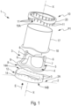
- each heart valve 3 (artificial) comprises, as shown in the figure 1 , a base 4 of annular shape, which is provided, on a downstream face 5, with three legs 6.
- the heart valve 3 also comprises three leaflets 7.
- Each leaflet 7 is fixed to two adjacent legs 6 and to the base 4.
- the three leaflets 7 of the heart valve 3 are configured to open and close under the action of the pressure in the upstream part.
- the terms upstream and downstream are defined according to the direction of blood circulation through the heart valve 3, as illustrated by an arrow E on the figures 1 , 2 , 5 And 7 .
- the base 4 has an upstream face 8, opposite the downstream face 5, and it includes a flange 9 which surrounds it (around its entire outer periphery).
- the upstream face 8 (as well as the collar 9) can have varied shapes. In a first embodiment (not shown), the face 8 upstream and the collar 9 are flat. Furthermore, in a second particular embodiment, as shown in particular on the figures 1 And 5 , the upstream face 8 and the collar 9 are curved or wavy, for example in the general shape of a wave.
- the fixing system 1 has the function of fixing such a heart valve 3, whatever the shape of its base 4, on the heart prosthesis 2.
- the fixing system 1 comprises, as shown in particular in Fig. 1, a male ring 10 of annular shape, which is provided on one face 10A (longitudinal) with pins 11.
- the pins 11 correspond to elements (in particular solid tubes) elongated protruding from face 10A.
- the male ring 10 (which notably comprises an annular support 20 and the pins 11 secured to the annular support 20) is a single piece, which makes it easier to produce.
- This one-piece part is, for example, made of titanium.
- the pins represent individual elements which are attached (for example welded or glued) to the annular support.
- the fixing system 1 also comprises a cooperating part 12 intended to cooperate with the male ring 10.
- This cooperating part 12 is provided with openings 13.
- Each of the openings 13 is intended to receive a pin 11 of the male ring 10 in a position PF fixing ( figures 3, 4 And 6 ).
- the cooperating part 12 thus comprises at least as many openings 13 as the male ring 10 comprises pins 11, and the pins 11 and the openings 13 are formed and arranged so that each of the pins 11 can be inserted into an opening 13.
- the fixing position PF represents the position in which the heart valve 3 is integrated into the heart prosthesis 2 and fixed, in its final position, on the heart prosthesis 2 using the fixing system 1.
- the male ring 10 is intended to be secured to the cardiac prosthesis 2.
- the cooperating part 12 is intended to be secured to the cardiac prosthesis 2.
- Different embodiments are envisaged for this connection, as specified below.
- the pins 11 and the openings 13 are configured, as also specified below, in such a way that the pins 11 pass through the collar 9 (formed for example of a silicone strip and a porous PTFE fabric) of the heart valve 3, before entering the openings 13, in the fixing position PF.
- the male ring 10 and the cooperating part 12 surround the flange 9 of the heart valve 3, as shown in the figures 3, 4 And 6 .
- the pins 11 are held by lateral contact in the openings 13, which makes it possible to secure the male ring 10 to the cooperating part 12 and hold them together, and this possibly (in one embodiment particular) with the help of an additional element (for example a staple).
- This connection makes it possible to maintain the heart valve 3 via the flange 9 and thus to fix the heart valve 3 to the cooperating part 12 and, consequently, to the cardiac prosthesis 2 (to which the cooperating part 12 is secured) .
- the male ring 10 and the cooperating part 12 each have a so-called contact face 10A and 14A ( figure 1 ).
- the contact faces 10A and 14A are intended to grip the flange 9 in the fixing position PF.
- These contact faces 10A and 14A have shapes adapted to the shape of the flange 9 and therefore to the shape of the base 4.
- the fixing system 1 can thus be adapted to the shape of the collar 9 and the base 4 of the heart valve 3. It can in particular be adapted to a heart valve 3 having a corrugated base 4.
- the fixing system 1 allows the fixing of any type of usual heart valve 3 and in particular a heart valve 3 with a non-planar base 4, for its integration into the heart prosthesis 2.
- the fixing system 1 can be used either for fixing a heart valve 3 intended for the ejection of blood out of the heart prosthesis 2, or for fixing a heart valve 3 intended for admission blood in the cardiac prosthesis 2, as specified above.
- the fixing system 1 can be produced in different ways. It can, in particular, be produced in two different ways depending on the type of connection of the cooperating part 12 or of the male ring 10 to the cardiac prosthesis 2.
- the cooperating part 12 is a female ring 14, that is to say an independent part intended to be linked to the cardiac prosthesis 2.
- the female ring 14 represents a counterform of the male ring 10.
- one of the two rings (the male ring 10 or the female ring 14) is fixed on the cardiac prosthesis 2.
- the female ring 14 is fixed in the usual manner on the cardiac prosthesis 2
- the male ring 10 is fixed in the usual manner on the cardiac prosthesis 2.
- the cooperating part 12 corresponds to a part 15, 16 of the cardiac prosthesis 2, as shown in two different variants on the figures 5 to 7 , namely a first variant on the figures 5 and 6 for fixing a heart valve 3 intended on ejection and a second variant on the Figure 7 for fixing a heart valve 3 intended for admission.
- the cooperating part 12 is therefore a female ring 14, for example made of titanium, initially independent and separated from the cardiac prosthesis 2, which has an upstream face 14B of particular shape, intended to come into contact with the cardiac prosthesis 2.
- This shape particular is complementary to the shape of a downstream face 2A called reception (represented very schematically on the figure 1 ) of the cardiac prosthesis 2.
- This first embodiment comprising the female ring 14, shown on the figures 1 to 4 , relates to a fixing system 1 for fixing a heart valve 3 intended for ejection.
- the fixing system 1 has the function of connecting to the cardiac prosthesis 2, in addition to the heart valve 3, also a conduit 17.
- This conduit 17 is intended to bring blood ejected from the cardiac prosthesis 2 (in the direction of arrow E) through the heart valve 3 to an artery (aorta or pulmonary artery) to which the conduit 17 is sutured in the usual manner.
- the conduit 17 made of fabric also includes a collar 18 at its upstream end.
- This collar 18, for example made of polyester, has a shape similar to the collar 9 of the heart valve 3.
- the pins 11 of the male ring 10 are intended to pass through (or pierce) also the collar 18 of conduit 17.
- the flange 9 of the heart valve 3 and where appropriate, the flange 18 of the conduit 17 must either include holes (of appropriate size), or (preferably) be made in a material allowing the pins 11 to pierce them.
- THE figures 1 , 2 and 3 show three successive steps during the fixation of the heart valve 3 and the conduit 17 on the heart prosthesis 2.
- the pins 11 of the male ring 10 therefore pierce the flange 18 of the conduit 17 as well as the flange 9 of the heart valve 3 before being inserted into the openings 13 of the female ring 14.
- the pins 11 of the male ring 10 are arranged parallel to the longitudinal axis XX of the heart valve 3 and of the conduit 17 when the male ring 10 is positioned coaxially with respect to this longitudinal axis, XX, as shown on the figures 1 to 7 .
- the female ring 14 comprises openings 13 of cylindrical shape, that is to say rectilinear, which are inclined relative to the longitudinal axis XX, that is to say their present orientation a non-zero angle relative to this longitudinal axis XX as shown on the figure 4 ,
- the pins 11 are caused to bend (or curve), as shown in the figure 4 . Consequently, by penetrating the openings 13, the pins 11 change direction and they present a bend 11A ( figure 4 ) in their PF fixing position. In a variant embodiment (not shown), they can have another curved shape, different from this shape with an elbow.
- the female ring 14 can be adapted to the content and shape of the cardiac prosthesis 2 and thus facilitates the integration of the heart valve 3.
- the male ring 10 and the female ring 14 can be adapted to allow fixation, whatever the embodiment considered, of any type of heart valve 3 without having to modify the design of the heart prosthesis 2.
- the fixing system 1 can be produced in different sizes and/or shapes in order, in particular, to adapt to various surgical heart valves 3.
- the second embodiment provides for removing the female ring by adapting the shape of a part of the cardiac prosthesis 2 to a counterform of the male ring 10.
- the cooperating part 12 therefore corresponds to a part 15, 16 of the cardiac prosthesis 2.
- This second embodiment can also be used for fixing a heart valve 3 intended for ejection or for fixing a heart valve 3 intended for admission.
- the cooperating part 12 corresponds to a part 15 of the heart prosthesis 2.
- This part 15 of the heart prosthesis 2 comprises, in this example, a tubular element (or section) 19.
- the tubular element 19 is provided all around its internal periphery 19A with a rim 21 of shape adapted to the shape of the base 4 of the heart valve 3.
- the wave shape of the heart valve 3 is thus integrated into the body of the cardiac prosthesis 2.
- the upstream face 8 of the base 4 of the heart valve 3 rests on this rim 21 in the fixing position PF, as shown in the Figure 6 .
- the pins 11 of the male ring 10 always have the function of piercing the flange 18 of the conduit 17 and the flange 9 of the heart valve 3, before being housed in the cooperating part 1, previously machined in the body of the cardiac prosthesis 2.
- the openings 13 are parallel to the longitudinal axis XX of the fixing system 1, so that, in the fixing position PF, the pins 11 are not bent (or curved) but remain rectilinear and parallel to the longitudinal axis XX, as visible on the Figure 6 .
- a clip 22 can be provided which is produced in the usual manner to hold the assembled parts together. To do this, we preferably provide a usual 22A groove ( Figure 6 ), intended to receive the clip 22.
- the pins 11 can have a constant diameter.
- the pins 11 have a diameter which reduces towards their free end (that is to say their end opposite to that which is linked to the face 10A of the male ring 10), which allows to facilitate assembly and to reinforce support, when they are inserted into cylindrical openings 13 (that is to say of constant diameter).
- This first variant of the second embodiment comprising part 15 as a counterform of the male ring 10 allows good adaptation to the cardiac prosthesis and makes it possible to minimize the bulk of the fixing system 1.
- This variant which requires modifying the design of the cardiac prosthesis 2 if the shape (for example) the model of the heart valve 3 changes, however, offers the advantage of reducing the protruding height of the legs of the heart valve 3.
- the second variant of the second embodiment is intended to fix a heart valve 3 used for admission.
- the free ends of the leaflets 7 of the heart valve 3 are directed towards the heart prosthesis 2, that is to say in the opposite direction to the embodiment of the figures 5 and 6 .
- the cooperating part 12 corresponds to a part 16 of the cardiac prosthesis 2.
- This part 16 of the cardiac prosthesis 2 comprises, in this example, a tubular element (or section) 24.
- the tubular element 24 is provided all around its internal periphery 24A with a rim 25 of shape adapted to the shape of the base 4 of the heart valve 3.
- the wave shape of the heart valve 3 is thus integrated into the body of the cardiac prosthesis 2.
- the face 8 upstream of the base 4 of the heart valve 3 rests on this rim 25 in the fixing position (not shown).
- the male ring 10 which is in contact with the blood, is made hemocompatible.
- a retaining ring 26 preferably a metal ring, is used to hold the male ring 10 with the pins 11 and the heart valve 3 in the cardiac prosthesis 2 until the time comes. install it on a usual metal bezel 27, already in place in the patient's thorax, during implantation of the cardiac prosthesis 2.
- a retaining ring 26 preferably a metal ring
- FR-2 902 343 And FR-2 902 344 describe a system of cooperating glasses for admissions of a cardiac prosthesis.
- the annular support 20 of the male ring 10 can be sized and shaped to achieve this retention (before installation on the metal bezel), instead of the retention ring 26.
- the part or parts of the fixing system 1 in contact with the blood can be covered with a knitted prosthesis (polyester yarn knitting weave).
- this polyester fabric is cut as close as possible to the shape of the ring, it is wrapped around the ring and it is sutured to be held.
- the method of setting up the fixing system 1 comprises at least one operation consisting of piercing the flange 9 of the heart valve 3 (and where appropriate the flange 18 of the conduit 17) by the pins 11 of the male ring 10 and to insert said pins 11 into the cooperating openings 13 of the cooperating part 12.
- said method comprises other steps implemented before and after this operation.
- fixation system 1 replaces suture operations, while providing a rigid framework for the heart valve 3, which facilitates its integration into the design of the heart prosthesis 2.
Landscapes
- Health & Medical Sciences (AREA)
- Engineering & Computer Science (AREA)
- Heart & Thoracic Surgery (AREA)
- Cardiology (AREA)
- Biomedical Technology (AREA)
- Veterinary Medicine (AREA)
- Life Sciences & Earth Sciences (AREA)
- Animal Behavior & Ethology (AREA)
- General Health & Medical Sciences (AREA)
- Public Health (AREA)
- Anesthesiology (AREA)
- Hematology (AREA)
- Mechanical Engineering (AREA)
- Oral & Maxillofacial Surgery (AREA)
- Transplantation (AREA)
- Vascular Medicine (AREA)
- Prostheses (AREA)
- External Artificial Organs (AREA)
Applications Claiming Priority (1)
| Application Number | Priority Date | Filing Date | Title |
|---|---|---|---|
| FR2300413A FR3144913B1 (fr) | 2023-01-17 | 2023-01-17 | Système de fixation d’une valve cardiaque sur une prothèse cardiaque et prothèse cardiaque pourvue d’un tel système de fixation. |
Publications (1)
| Publication Number | Publication Date |
|---|---|
| EP4403137A1 true EP4403137A1 (de) | 2024-07-24 |
Family
ID=85726950
Family Applications (1)
| Application Number | Title | Priority Date | Filing Date |
|---|---|---|---|
| EP23197327.2A Pending EP4403137A1 (de) | 2023-01-17 | 2023-09-14 | System zur befestigung eines herzklappenventils an einer herzprothese und herzprothese mit einem solchen befestigungssystem. |
Country Status (5)
| Country | Link |
|---|---|
| EP (1) | EP4403137A1 (de) |
| JP (1) | JP2026501467A (de) |
| CN (1) | CN120548154A (de) |
| FR (1) | FR3144913B1 (de) |
| WO (1) | WO2024153355A1 (de) |
Families Citing this family (1)
| Publication number | Priority date | Publication date | Assignee | Title |
|---|---|---|---|---|
| CN119971298B (zh) * | 2025-04-11 | 2025-06-17 | 四川大学华西医院 | 低热伤害的串联式心室辅助循环装置 |
Citations (7)
| Publication number | Priority date | Publication date | Assignee | Title |
|---|---|---|---|---|
| FR2784585A1 (fr) | 1998-10-15 | 2000-04-21 | Gie Carmat | Prothese cardiaque implantable a chambres ventriculaires independantes |
| US6059827A (en) * | 1998-05-04 | 2000-05-09 | Axya Medical, Inc. | Sutureless cardiac valve prosthesis, and devices and methods for implanting them |
| US6346071B1 (en) * | 1999-07-16 | 2002-02-12 | World Heart Corporation | Inflow conduit assembly for a ventricular assist device |
| FR2902345A1 (fr) | 2006-06-15 | 2007-12-21 | Carpentier Matra Carmat | Prothese cardiaque monobloc implantable en position anatomique |
| FR2902344A1 (fr) | 2006-06-15 | 2007-12-21 | Carpentier Matra Carmat | Dispositif de raccordement entre une prothese cardiaque et les oreillettes naturelles |
| FR2902343A1 (fr) | 2006-06-15 | 2007-12-21 | Carpentier Matra Carmat | Dispositif de connexion rapide entre une prothese cardiaque totalement implantable et des oreillettes naturelles |
| US20110190880A1 (en) * | 2008-05-19 | 2011-08-04 | Amalaha Leonard D | Wholly implantable non-natural heart for humans |
-
2023
- 2023-01-17 FR FR2300413A patent/FR3144913B1/fr active Active
- 2023-09-14 WO PCT/EP2023/075311 patent/WO2024153355A1/fr not_active Ceased
- 2023-09-14 CN CN202380091068.2A patent/CN120548154A/zh active Pending
- 2023-09-14 EP EP23197327.2A patent/EP4403137A1/de active Pending
- 2023-09-14 JP JP2025540309A patent/JP2026501467A/ja active Pending
Patent Citations (7)
| Publication number | Priority date | Publication date | Assignee | Title |
|---|---|---|---|---|
| US6059827A (en) * | 1998-05-04 | 2000-05-09 | Axya Medical, Inc. | Sutureless cardiac valve prosthesis, and devices and methods for implanting them |
| FR2784585A1 (fr) | 1998-10-15 | 2000-04-21 | Gie Carmat | Prothese cardiaque implantable a chambres ventriculaires independantes |
| US6346071B1 (en) * | 1999-07-16 | 2002-02-12 | World Heart Corporation | Inflow conduit assembly for a ventricular assist device |
| FR2902345A1 (fr) | 2006-06-15 | 2007-12-21 | Carpentier Matra Carmat | Prothese cardiaque monobloc implantable en position anatomique |
| FR2902344A1 (fr) | 2006-06-15 | 2007-12-21 | Carpentier Matra Carmat | Dispositif de raccordement entre une prothese cardiaque et les oreillettes naturelles |
| FR2902343A1 (fr) | 2006-06-15 | 2007-12-21 | Carpentier Matra Carmat | Dispositif de connexion rapide entre une prothese cardiaque totalement implantable et des oreillettes naturelles |
| US20110190880A1 (en) * | 2008-05-19 | 2011-08-04 | Amalaha Leonard D | Wholly implantable non-natural heart for humans |
Also Published As
| Publication number | Publication date |
|---|---|
| JP2026501467A (ja) | 2026-01-15 |
| FR3144913B1 (fr) | 2024-11-29 |
| WO2024153355A1 (fr) | 2024-07-25 |
| CN120548154A (zh) | 2025-08-26 |
| FR3144913A1 (fr) | 2024-07-19 |
Similar Documents
| Publication | Publication Date | Title |
|---|---|---|
| EP2986255B1 (de) | Implantate zum einsatz in einer blutzirkulationspassage mit einem system zum trennen der proximalen arme | |
| EP2779943B1 (de) | Implantat zur positionierung in einem blutflussdurchgang und entsprechende behandlungsvorrichtung | |
| EP1923012B1 (de) | Implantat für die interphalangäre Arthrodese, entsprechender chirurgischer Teilesatz und Herstellungsverfahren | |
| EP3145448B1 (de) | Prothetische mitral- oder trikuspidalherzklappe | |
| CA3003506C (fr) | Prothese de valve cardiaque mitrale ou tricuspide | |
| EP1411865B1 (de) | Anordnung zum einsetzen einer ventilprothese in ein körpergefäss | |
| FR2964855A1 (fr) | Implant destine a etre place dans un passage sanguin auriculo-ventriculaire | |
| EP2802292A1 (de) | Verankerungsvorrichtung für eine künstliche herzklappe | |
| EP1229868A1 (de) | Kapselsackring und system bestehend aus ring und dessen einführungsvorrichtung | |
| FR2910269A1 (fr) | Materiel de traitement d'une valve cardiaque,en particulier d'une valve mitrale | |
| EP1928355B1 (de) | Prothese für ein aufsteigendes aortensegment | |
| WO2024153355A1 (fr) | Système de fixation d'une valve cardiaque sur une prothèse cardiaque et prothèse cardiaque pourvue d'un tel système de fixation | |
| CA3158611A1 (fr) | Dispositif d'ancrage d'une pompe cardiaque et ensemble de pose d'une pompe cardiaque equipe d'un tel dispositif d'ancrage | |
| EP2502577B1 (de) | Prothese zur Sicherstellung eines Anschlusses an einen anatomischen Kanal. | |
| EP3796953B1 (de) | Vorrichtung zur verankerung einer herzpumpe | |
| EP4070848B1 (de) | Vorrichtung zum verbinden einer implantierbaren herzprothese mit dem gefässnetz eines patienten und herzprothese, die eine solche verbindungsvorrichtung umfasst | |
| CA2923113A1 (fr) | Prothese intra-laryngee | |
| WO1995005133A1 (fr) | Valve cardiaque implantable | |
| FR3079409A1 (fr) | Systeme de traitement d'une valve cardiaque, en particulier une valve mitrale ou tricuspide | |
| FR2748653A1 (fr) | Prothese valvulaire aortique a pontage coronarien intra-aortique et kit chirurgical de pose |
Legal Events
| Date | Code | Title | Description |
|---|---|---|---|
| PUAI | Public reference made under article 153(3) epc to a published international application that has entered the european phase |
Free format text: ORIGINAL CODE: 0009012 |
|
| STAA | Information on the status of an ep patent application or granted ep patent |
Free format text: STATUS: THE APPLICATION HAS BEEN PUBLISHED |
|
| AK | Designated contracting states |
Kind code of ref document: A1 Designated state(s): AL AT BE BG CH CY CZ DE DK EE ES FI FR GB GR HR HU IE IS IT LI LT LU LV MC ME MK MT NL NO PL PT RO RS SE SI SK SM TR |
|
| STAA | Information on the status of an ep patent application or granted ep patent |
Free format text: STATUS: REQUEST FOR EXAMINATION WAS MADE |
|
| 17P | Request for examination filed |
Effective date: 20240807 |
|
| RBV | Designated contracting states (corrected) |
Designated state(s): AL AT BE BG CH CY CZ DE DK EE ES FI FR GB GR HR HU IE IS IT LI LT LU LV MC ME MK MT NL NO PL PT RO RS SE SI SK SM TR |
|
| STAA | Information on the status of an ep patent application or granted ep patent |
Free format text: STATUS: EXAMINATION IS IN PROGRESS |
|
| 17Q | First examination report despatched |
Effective date: 20250911 |