EP4402779B1 - Wicklungsführung für einen rotor eines elektromotors - Google Patents
Wicklungsführung für einen rotor eines elektromotors Download PDFInfo
- Publication number
- EP4402779B1 EP4402779B1 EP22802005.3A EP22802005A EP4402779B1 EP 4402779 B1 EP4402779 B1 EP 4402779B1 EP 22802005 A EP22802005 A EP 22802005A EP 4402779 B1 EP4402779 B1 EP 4402779B1
- Authority
- EP
- European Patent Office
- Prior art keywords
- angle
- winding guide
- longitudinal axis
- ribs
- rotor
- Prior art date
- Legal status (The legal status is an assumption and is not a legal conclusion. Google has not performed a legal analysis and makes no representation as to the accuracy of the status listed.)
- Active
Links
Images

Classifications
-
- H—ELECTRICITY
- H02—GENERATION; CONVERSION OR DISTRIBUTION OF ELECTRIC POWER
- H02K—DYNAMO-ELECTRIC MACHINES
- H02K3/00—Details of windings
- H02K3/46—Fastening of windings on the stator or rotor structure
- H02K3/52—Fastening salient pole windings or connections thereto
- H02K3/527—Fastening salient pole windings or connections thereto applicable to rotors only
-
- H—ELECTRICITY
- H02—GENERATION; CONVERSION OR DISTRIBUTION OF ELECTRIC POWER
- H02K—DYNAMO-ELECTRIC MACHINES
- H02K1/00—Details of the magnetic circuit
- H02K1/06—Details of the magnetic circuit characterised by the shape, form or construction
- H02K1/22—Rotating parts of the magnetic circuit
- H02K1/26—Rotor cores with slots for windings
-
- H—ELECTRICITY
- H02—GENERATION; CONVERSION OR DISTRIBUTION OF ELECTRIC POWER
- H02K—DYNAMO-ELECTRIC MACHINES
- H02K3/00—Details of windings
- H02K3/32—Windings characterised by the shape, form or construction of the insulation
- H02K3/34—Windings characterised by the shape, form or construction of the insulation between conductors or between conductor and core, e.g. slot insulation
-
- H—ELECTRICITY
- H02—GENERATION; CONVERSION OR DISTRIBUTION OF ELECTRIC POWER
- H02K—DYNAMO-ELECTRIC MACHINES
- H02K2203/00—Specific aspects not provided for in the other groups of this subclass relating to the windings
- H02K2203/12—Machines characterised by the bobbins for supporting the windings
-
- H—ELECTRICITY
- H02—GENERATION; CONVERSION OR DISTRIBUTION OF ELECTRIC POWER
- H02K—DYNAMO-ELECTRIC MACHINES
- H02K2213/00—Specific aspects, not otherwise provided for and not covered by codes H02K2201/00 - H02K2211/00
- H02K2213/03—Machines characterised by numerical values, ranges, mathematical expressions or similar information
Definitions
- the present invention relates generally to electrical machines.
- the invention finds a particularly advantageous application in the production of wound rotor synchronous electrical machines, and in particular traction motors for motor vehicles.
- An electrical machine such as a motor typically consists of a rotor and a stator.
- the rotor is a moving part that rotates, while the stator is a stationary part.
- the rotation speed of a rotor in a motor vehicle traction motor exceeds 10,000 revolutions per minute, which generates high mechanical stresses.
- a wound-type rotor capable of withstanding such stresses is described, for example, in the document WO2020020551 .
- the rotor comprises a shaft which rotates about its axis, and a stack of laminations mounted coaxially on the shaft. These laminations form a frame which comprises a tubular body and magnetic poles which extend radially projecting from this body.
- a coil of electric wire is then provided to be wound around each pole.
- a winding guide is provided at each end of the superposition of sheets.
- These guides each have a circular base (extending in the extension of the tubular body), teeth which rise from the circular base (in the extension of the poles) and which each carry a cantilevered head.
- the electric wire is designed to be wound around each tooth and the corresponding pole.
- the heads facilitate the winding of the electric wire and they allow the radial retention of the windings when the rotor turns.
- the shapes of the winding guides are designed so that the electric wire can be automatically wound around the poles and teeth, positioning itself correctly.
- the idea is to wind the electrical wire so that the turns are positioned side by side in all the space allotted to them, and overlap in several layers.
- the arrangement of the turns is conditioned by the radial dimension of the allocated space, which is delimited between the head and the base of each tooth of the winding guide.
- this radial dimension would be constant throughout the allocated space, so that the layers of coils all have the same space to arrange themselves.
- Such an injection manufacturing method is carried out using molds whose shapes must be designed to allow the winding guides to be removed from the mold.
- a wound-type rotor capable of withstanding high-intensity centrifugal forces is described in the document KR 2000 0016311 U .
- the present invention proposes not to produce the winding guides by means of another manufacturing method, but rather to design guides in such a way as to take into consideration the aforementioned defect of the injection manufacturing method.
- the idea is therefore to very locally reduce the draft angle required for demolding at the level of small narrow surfaces (the tops of the ribs) on which the electric wire can rest, while leaving the majority of the inner face of this head inclined with a sufficient draft angle to allow the part to be demolded.
- the small ribs have little or no draft angle, but have dimensions small enough not to hinder demolding. Thanks to these ribs, the winding space delimited between the base and the tops of these ribs has a constant width, which ensures better arrangement of the turns of electric wire.
- a motor vehicle comprising wheels and a powertrain for rotating at least part of said wheels, which comprises an electric machine as mentioned above.
- This electrical machine could be a current generator. In this case, it is rather a motor vehicle traction motor, which motor may possibly have a generator function in certain operating modes of the vehicle.
- This engine is therefore part of a powertrain installed on the chassis of a motor vehicle and coupled to the wheels of this vehicle.
- This motor consists of various components, including a casing that houses a stator and a rotor. While the stator is fixed in the casing, the rotor is mounted to rotate about a longitudinal axis A1.
- the rotor is of the wound type (see Figure 4 ). It therefore has a 1A chassis and 20 coils of electric wire wound on the 1A frame.
- Chassis 1A is shown in the Figure 1 .
- This chassis 1A comprises a shaft 6 mounted rotatably around the longitudinal axis A1. It also comprises a stack 2 of identical sheets, mounted coaxially on the shaft.
- the sheets of this stack 2 extend in a radial plane perpendicular to the longitudinal axis A1. In this radial plane, the sheets all have an identical outline, with a body 3A in the form of a disc pierced for the passage of the shaft 6, and salient poles which are distributed regularly around the longitudinal axis A1.
- the sheets are mounted by shrink-fitting on the external surface of the rotor shaft 6, so that their salient poles overlap in line with each other and form “poles 3”.
- the stack 2 comprises eight poles 3. However, it could comprise a different number of poles, greater than or at least equal to two.
- Each pole 3 has a mushroom shape, with a foot 3B which extends radially towards the outside of the rotor, and a cap 3C which forms two ribs projecting laterally on either side of the foot 3B.
- the function of the ribs 3C is in particular to retain in the radial direction a winding of electrically conductive wire (which will be described in more detail later in this presentation), despite the centrifugal force experienced by this winding during the rotation of the rotor 1.
- winding guide 10 an element different from the sheets of the stack 2, here called “winding guide 10”.
- Two identical winding guides 10 are preferably provided at the two ends of the stack 2 of sheets, but only one of them will be described here.
- Each winding guide 10 is essentially provided to facilitate the winding of the electric wire around the poles 3.
- Each winding guide 10 has, in the example shown in the Figure 1 , the particularity of being made up of a 10A metal core overmolded by a 10B plastic structure.
- the metal core 10A of the guide flange 10 has a shape homologous to that of the sheets of the stack 2, with a circular base pierced for the passage of the shaft 6, which extends in a radial plane perpendicular to the longitudinal axis A1 of the shaft. of the rotor, and salient poles. However, here, these salient poles have the shape of tabs folded at right angles towards the front.
- the front of the rotor can be defined as the side on which the winding guide 10 in question is located.
- the rear will be the opposite side.
- the term “internal” or “inner” will designate the side facing the longitudinal axis A1 and the term “external” or “outer” will designate the opposite side.
- the plastic structure 10B forms with the metal core 10A a circular base 11 and teeth 12 which rise radially relative to the base 11. It also forms, at the end of each tooth 12, a head 13 which projects on either side of the teeth 12 and towards the front.
- the teeth 12 and the heads 13 are here all identical but can be asymmetrical between the front and opposite side. We will therefore only describe one of these teeth and one of these heads, with reference to the Figure 2 .
- the tooth 12 has a section (in a plane orthogonal to the radial axis along which the tooth rises) of generally rectangular shape, with two rounded front edges. These rounded edges are striated so as to guide the first layer of turns of electric wire which will be wound around the tooth 12.
- the head 13 here extends to the free end of the tooth 12, and it projects forward and on the lateral sides of the latter, in a cantilevered manner.
- the head 13 which has the shape of a substantially flat and rectangular plate, extends substantially in a plane orthogonal to the radial axis of the tooth 12.
- Each head 13 then has an internal face 14 located opposite the base 11.
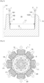
- the base 11 carries stops 18, two of which extend opposite each head 13 in order to delimit with it a winding space 19.
- the Figure 4 clearly illustrates the coils 20 of electric wires wound in this winding space, between the stops 18 and the heads 13.
- the objective of the invention is that the width of this winding space 19 (measured radially relative to the longitudinal axis A1) is substantially constant over the entire height of the space (the height being measured axially).
- the winding guide can be made of plastic to facilitate the electrical insulation of the wires and prevent their damage.
- the most common manufacturing process for plastics is injection molding, which we hope to be able to use. Here it is intended to be made in a mold in two parts that separate by moving them apart along an axis parallel to the longitudinal axis A1.
- the internal face 14 of the head 13 is not square with respect to the tooth 12 (it has a non-zero clearance angle) and it is not not perfectly flat.
- main portion 141 which is flat which is inclined by a non-zero draft angle ⁇ relative to the longitudinal axis, and ribs 142 which extend projecting from the main portion 141 and whose apexes 142A are flat and inclined relative to the longitudinal axis A1 by a small angle ⁇ between 0 (inclusive) and the draft angle ⁇ (exclusive).
- the clearance angle ⁇ is oriented such that the head 13 tapers from the edge 143 of the head 13 which is attached to the tooth 12 towards the opposite free edge 144.
- the small angle ⁇ is oriented in the same way.
- the draft angle ⁇ is greater than 1.5 degrees and of the order of 2 degrees. Such an angle makes it easier to demould the winding guide.
- the small angle ⁇ is less than or equal to 0.5 degrees, and preferably of the order of 0 to 0.2 degrees. This small angle is such that the winding space 19 has a substantially constant width over its entire height, which ensures winding of the electric wire according to the desired shape.
- the ribs 142 are all identical and parallel to each other. They extend lengthwise from the edge 143 of the head 13 which is attached to the tooth 12 (or at the height of this edge), towards the opposite edge 144 of the head.
- This width is approximately 3 mm when the total width of the head is around 40 to 60 mm.
- edges of the ribs are not straight but also have pronounced draft angles.
- the ribs 142 are located at a distance from each other. This distance is at most equal to three times the diameter of the wound electric wire, which prevents the latter from bending between the ribs. It is preferably between two and three times this diameter.
- the ratio of the surface area occupied by the ribs 142 to the total surface area of the internal face 14 of the tooth 13 is preferably greater than 50%.
- stops 18 On the other side of the winding space 19 with respect to the head 13, there is provided two stops 18 which, as shown in the Figure 4 , here present the shapes of plots. These stops could of course present different shapes (the Figure 1 represents for example a variant of the guide in which the stops have the shape of walls rather than studs).
- each pad thus has a side 181 oriented towards the head 13 which is inclined at an angle ⁇ relative to the longitudinal axis A1 at least equal to the clearance angle ⁇ .
- a rib 182 projects from this side 181 of the stud.
- it has a shape identical to that of the ribs 142 of the head 13.
- This rib 182 therefore has a flat top which is inclined relative to the longitudinal axis A1 by a reduced angle ⁇ , preferably between 0 and 0.5 degrees (limits included).
- the winding space 19 has a width L1 which increases very little from tooth 12 towards the front.
- the assembly of the rotor 1 then consists of positioning two winding guides 10 at the ends of the sheets of the chassis 1A, so that their teeth 12 extend in line with the poles 3, then winding the electric wire so that it forms a coil 20 around each pair of axially opposite teeth 12 and the pole located between these teeth 12.
- the turns of the electric wire are automatically positioned side by side, in several layers. Due to the reduced values of the angles ⁇ and ⁇ , the width L1 available to each layer of turns varies little, which ensures reliable automatic winding of the electric wire.
- the rotor rotates at a high speed, so that the coils 20 are subjected to high intensity centrifugal forces F1 (see Figure 4 ).
- the well-executed winding allows every other layer of electric wire to rest on the head 13 of the winding guide 10, which then ensures a solid hold of the coils 20 of electric wire.
- ribs are not parallel to each other, or that they differ from each other, or that they have variable widths.
Landscapes
- Engineering & Computer Science (AREA)
- Power Engineering (AREA)
- Iron Core Of Rotating Electric Machines (AREA)
- Insulation, Fastening Of Motor, Generator Windings (AREA)
- Manufacture Of Motors, Generators (AREA)
Claims (11)
- Wicklungsführung (10) für den Rotor einer elektrischen Maschine, umfassend:- eine im Wesentlichen kreisförmige Basis (11) um eine Längsachse (A1),- Zähne (12), die sich radial von der Basis (11) erheben, und- Köpfe (13), die sich an den freien Enden der Zähne (12) erstrecken und freitragend über die Zähne (12) hinausragen,wobei mindestens einer der Köpfe (13) eine Innenseite (14) aufweist, die zur Basis (11) gedreht ist und die Folgendes enthält:- einen flachen Hauptabschnitt (141), der um einen ersten Winkel (α), der strikt größer als 0 Grad ist, in Bezug auf die Längsachse (A1) geneigt ist, dadurch gekennzeichnet, dass- Rippen (142), die sich vorspringend von dem Hauptabschnitt (141) erstrecken und deren Scheitelpunkte (142A) flach und in Bezug auf die Längsachse (A1) um einen zweiten Winkel (β) zwischen null Grad eingeschlossen und dem ausgeschlossenen ersten Winkel (α) geneigt sind.
- Wicklungsführung (10) nach dem vorhergehenden Anspruch, wobei der erste Winkel (α) größer als 1 Grad ist und vorzugsweise zwischen 1,5 und 2,5 Grad beträgt.
- Wicklungsführung (10) nach einem der vorhergehenden Ansprüche, wobei der zweite Winkel (β) kleiner als 0,5 Grad ist und vorzugsweise zwischen 0 und 0,2 Grad beträgt.
- Wicklungsführung (10) nach einem der vorhergehenden Ansprüche, wobei sich der Kopf (13) von einer Seite des Zahns (12) aus erstreckt und eine erste Kante (143), die mit dem Zahn (12) verbunden ist, und eine zweite gegenüberliegende, freie Kante (144) aufweist, wobei sich die Rippen (142) bei mindestens einem Teil von ihnen in der Länge von der ersten Kante (143) in Richtung der zweiten Kante (144) erstrecken.
- Wicklungsführung (10) nach dem vorhergehenden Anspruch, wobei die Rippen (142) an der ersten Kante (143) eine Dicke von im Wesentlichen null aufweisen.
- Wicklungsführung (10) nach einem der vorhergehenden Ansprüche, wobei sich die Rippen (142) parallel zueinander erstrecken.
- Wicklungsführung (10) nach dem vorhergehenden Anspruch, wobei die Rippen (142) in einem Abstand von weniger als dem Dreifachen des Durchmessers eines um den Zahn (12) zu wickelnden elektrischen Drahts voneinander entfernt sind.
- Wicklungsführung (10) nach einem der vorhergehenden Ansprüche, wobei Anschläge (18) vorgesehen sind, die sich von der Basis (11) ausgehend, im Wesentlichen parallel zu den Köpfen (13), erheben, um mit diesen Wicklungsräume eines elektrischen Drahts abzugrenzen, und wobei mindestens einer der Anschläge (18) eine Außenfläche aufweist, die eine Seite (181), die um einen dritten Winkel (δ), der strikt größer als 0 Grad ist, in Bezug auf die Längsachse (A1) geneigt ist, und mindestens eine Rippe (182) enthält, die sich vorspringend von dieser Seite (181) erstreckt und deren Scheitelpunkt flach und in Bezug auf die Längsachse (A1) um einen vierten Winkel (ε) zwischen null Grad eingeschlossen und dem ausgeschlossen dritten Winkel geneigt ist.
- Rotor (1) für eine elektrische Maschine, der einen Rahmen (1A) umfasst, der um eine Längsachse (A1) verteilte Magnetpolelemente (3) enthält, die paarweise durch Nuten (4) getrennt sind, dadurch gekennzeichnet, dass der Rahmen (1A) an mindestens einem seiner Enden eine Wicklungsführung (10) nach einem der vorhergehenden Ansprüche enthält, deren Zähne (12) sich in der Verlängerung der Magnetpolelemente (3) erstrecken, und dadurch, dass er eine Spule (20) aus leitendem elektrischem Draht enthält, die um jedes Magnetpolelement (3) und den entsprechenden Zahn (12) gewickelt ist.
- Elektrische Maschine, die einen Stator umfasst, dadurch gekennzeichnet, dass sie einen Rotor (1) gemäß dem vorhergehenden Anspruch umfasst.
- Kraftfahrzeug, das Räder und einer Antriebseinheit zum rotierenden Antrieb mindestens eines Teils der Räder enthält, dadurch gekennzeichnet, dass die Antriebseinheit eine elektrische Maschine gemäß dem vorhergehenden Anspruch enthält.
Applications Claiming Priority (2)
| Application Number | Priority Date | Filing Date | Title |
|---|---|---|---|
| FR2109605A FR3127087B1 (fr) | 2021-09-14 | 2021-09-14 | Guide de bobinage pour rotor de machine électrique |
| PCT/EP2022/074916 WO2023041403A1 (fr) | 2021-09-14 | 2022-09-07 | Guide de bobinage pour rotor de machine électrique |
Publications (2)
| Publication Number | Publication Date |
|---|---|
| EP4402779A1 EP4402779A1 (de) | 2024-07-24 |
| EP4402779B1 true EP4402779B1 (de) | 2025-05-21 |
Family
ID=78212295
Family Applications (1)
| Application Number | Title | Priority Date | Filing Date |
|---|---|---|---|
| EP22802005.3A Active EP4402779B1 (de) | 2021-09-14 | 2022-09-07 | Wicklungsführung für einen rotor eines elektromotors |
Country Status (7)
| Country | Link |
|---|---|
| US (1) | US20240380271A1 (de) |
| EP (1) | EP4402779B1 (de) |
| JP (1) | JP2024531712A (de) |
| KR (1) | KR20240056586A (de) |
| CN (1) | CN118056345A (de) |
| FR (1) | FR3127087B1 (de) |
| WO (1) | WO2023041403A1 (de) |
Families Citing this family (2)
| Publication number | Priority date | Publication date | Assignee | Title |
|---|---|---|---|---|
| DE102023211376A1 (de) * | 2023-11-15 | 2025-05-15 | Mahle International Gmbh | Rotor |
| FR3162562A1 (fr) * | 2024-05-21 | 2025-11-28 | Ampere Sas | Agencement pour un rotor de machine électrique. |
Family Cites Families (8)
| Publication number | Priority date | Publication date | Assignee | Title |
|---|---|---|---|---|
| KR20000016311U (ko) * | 1999-01-29 | 2000-08-25 | 에릭 발리베 | 발전기의 보빈 회전방지구조 |
| JP3664608B2 (ja) * | 1999-05-25 | 2005-06-29 | 三菱電機株式会社 | 回転電機 |
| FR2984034B1 (fr) * | 2011-12-08 | 2014-08-22 | Renault Sa | Dispositif de guidage d'un ensemble de fils electriques pour rotor de moteur electrique |
| US10333365B2 (en) * | 2015-01-16 | 2019-06-25 | Hamilton Sundstrand Corporation | End winding support segment with integrated lubricant manifold |
| FR3084220B1 (fr) | 2018-07-23 | 2020-06-19 | Renault S.A.S | Dispositif de guidage de fils pour rotor de machine electrique synchrone de type a rotor bobine |
| DE102018128521A1 (de) * | 2018-11-14 | 2020-05-14 | Bayerische Motoren Werke Aktiengesellschaft | Stützeinrichtung für einen Rotor einer fremderregten Innenläufer-Synchronmaschine, Rotor, fremderregte Innenläufer-Synchronmaschine sowie Kraftfahrzeug |
| US11955858B2 (en) * | 2019-03-13 | 2024-04-09 | Top Co., Ltd. | Rotary machine and insulator |
| DE102019211262A1 (de) * | 2019-07-30 | 2021-02-04 | Brose Fahrzeugteile SE & Co. Kommanditgesellschaft, Würzburg | Spulenträger für eine Statorwicklung eines Elektromotors |
-
2021
- 2021-09-14 FR FR2109605A patent/FR3127087B1/fr active Active
-
2022
- 2022-09-07 EP EP22802005.3A patent/EP4402779B1/de active Active
- 2022-09-07 US US18/691,056 patent/US20240380271A1/en active Pending
- 2022-09-07 CN CN202280066973.8A patent/CN118056345A/zh active Pending
- 2022-09-07 JP JP2024516377A patent/JP2024531712A/ja active Pending
- 2022-09-07 KR KR1020247011669A patent/KR20240056586A/ko active Pending
- 2022-09-07 WO PCT/EP2022/074916 patent/WO2023041403A1/fr not_active Ceased
Also Published As
| Publication number | Publication date |
|---|---|
| FR3127087B1 (fr) | 2023-09-22 |
| FR3127087A1 (fr) | 2023-03-17 |
| KR20240056586A (ko) | 2024-04-30 |
| EP4402779A1 (de) | 2024-07-24 |
| US20240380271A1 (en) | 2024-11-14 |
| JP2024531712A (ja) | 2024-08-29 |
| WO2023041403A1 (fr) | 2023-03-23 |
| CN118056345A (zh) | 2024-05-17 |
Similar Documents
| Publication | Publication Date | Title |
|---|---|---|
| EP4402779B1 (de) | Wicklungsführung für einen rotor eines elektromotors | |
| EP3166210B1 (de) | Elektrisch umlaufende maschine, die mit einem stator ausgestattet ist | |
| WO2022069096A1 (fr) | Rotor de machine electrique et procede d'assemblage d'un tel rotor | |
| EP3662563A1 (de) | Rotor mit injiziertem käfig | |
| EP2283561B1 (de) | Rotor für elektrische drehmaschine mit interpolaren strukturen mit verringerter masse | |
| FR2901428A1 (fr) | Procede de realisation d'un rotor comportant une etape d'usinage de gorges dans les dents des poles et rotor obtenu par le procede | |
| EP2145376A2 (de) | Verfahren zur herstellung eines rotors für eine rotierende elektrische maschine, insbesondere einen generator | |
| EP3107193B1 (de) | Rotor mit stapelblechen | |
| WO2018083406A1 (fr) | Stator de machine electrique tournante muni de bobines a enroulement orthocyclique | |
| FR2818823A1 (fr) | Rotor de machine electrique tournante comportant un corps de bobine perfectionne et alternateur comportant un tel rotor | |
| FR2928790B1 (fr) | Procede d'enroulement d'un bobinage. | |
| WO2025078305A1 (fr) | Cale de maintien de fil électrique dans un encoche inter-pôles de rotor bobiné, rotor bobiné associé, et procédé de bobinage d'un rotor bobiné associé | |
| WO2019016242A1 (fr) | Machine electrique tournante comportant un dispositif de maintien de l'extremite d'un fil electrique participant au bobinage | |
| FR2532789A1 (fr) | Collecteur de machine electique tournante, et son procede de fabrication | |
| FR3153949A1 (fr) | Rotor de machine tournante électrique | |
| FR3158399A1 (fr) | Guide tete de bobine, rotor bobine associe et procede de bobinage d’un rotor bobine associe | |
| WO2018100309A1 (fr) | Rotor pour machine electrique tournante | |
| WO2017203156A1 (fr) | Démarreur muni d'un pignon ayant au moins une dent profilée | |
| FR3162562A1 (fr) | Agencement pour un rotor de machine électrique. | |
| FR2905534A1 (fr) | Stator pour machine electrique tournante, notamment un alternateur de vehicule automobile | |
| FR3152344A1 (fr) | Procédé amélioré pour la fabrication de stators inclinés avec enroulements statoriques avec des portions de conducteurs s parallèle | |
| FR3152675A1 (fr) | Stator pour machine électrique à flux axial | |
| FR3056350A1 (fr) | Segment de stator pour machine electrique tournante et procede de realisation d'un stator bobine correspondant | |
| FR3157719A1 (fr) | Procédé de bobinage in situ et ex situ pour machine électrique, et machine électrique associée | |
| EP4649574A1 (de) | Rotor für eine elektrische drehmaschine |
Legal Events
| Date | Code | Title | Description |
|---|---|---|---|
| STAA | Information on the status of an ep patent application or granted ep patent |
Free format text: STATUS: UNKNOWN |
|
| STAA | Information on the status of an ep patent application or granted ep patent |
Free format text: STATUS: THE INTERNATIONAL PUBLICATION HAS BEEN MADE |
|
| PUAI | Public reference made under article 153(3) epc to a published international application that has entered the european phase |
Free format text: ORIGINAL CODE: 0009012 |
|
| STAA | Information on the status of an ep patent application or granted ep patent |
Free format text: STATUS: REQUEST FOR EXAMINATION WAS MADE |
|
| 17P | Request for examination filed |
Effective date: 20240314 |
|
| AK | Designated contracting states |
Kind code of ref document: A1 Designated state(s): AL AT BE BG CH CY CZ DE DK EE ES FI FR GB GR HR HU IE IS IT LI LT LU LV MC MK MT NL NO PL PT RO RS SE SI SK SM TR |
|
| DAV | Request for validation of the european patent (deleted) | ||
| DAX | Request for extension of the european patent (deleted) | ||
| GRAP | Despatch of communication of intention to grant a patent |
Free format text: ORIGINAL CODE: EPIDOSNIGR1 |
|
| STAA | Information on the status of an ep patent application or granted ep patent |
Free format text: STATUS: GRANT OF PATENT IS INTENDED |
|
| INTG | Intention to grant announced |
Effective date: 20250129 |
|
| GRAS | Grant fee paid |
Free format text: ORIGINAL CODE: EPIDOSNIGR3 |
|
| GRAA | (expected) grant |
Free format text: ORIGINAL CODE: 0009210 |
|
| STAA | Information on the status of an ep patent application or granted ep patent |
Free format text: STATUS: THE PATENT HAS BEEN GRANTED |
|
| AK | Designated contracting states |
Kind code of ref document: B1 Designated state(s): AL AT BE BG CH CY CZ DE DK EE ES FI FR GB GR HR HU IE IS IT LI LT LU LV MC MK MT NL NO PL PT RO RS SE SI SK SM TR |
|
| REG | Reference to a national code |
Ref country code: GB Ref legal event code: FG4D Free format text: NOT ENGLISH |
|
| REG | Reference to a national code |
Ref country code: CH Ref legal event code: EP |
|
| REG | Reference to a national code |
Ref country code: DE Ref legal event code: R096 Ref document number: 602022015044 Country of ref document: DE |
|
| REG | Reference to a national code |
Ref country code: IE Ref legal event code: FG4D Free format text: LANGUAGE OF EP DOCUMENT: FRENCH |
|
| REG | Reference to a national code |
Ref country code: NL Ref legal event code: MP Effective date: 20250521 |
|
| PG25 | Lapsed in a contracting state [announced via postgrant information from national office to epo] |
Ref country code: FI Free format text: LAPSE BECAUSE OF FAILURE TO SUBMIT A TRANSLATION OF THE DESCRIPTION OR TO PAY THE FEE WITHIN THE PRESCRIBED TIME-LIMIT Effective date: 20250521 Ref country code: ES Free format text: LAPSE BECAUSE OF FAILURE TO SUBMIT A TRANSLATION OF THE DESCRIPTION OR TO PAY THE FEE WITHIN THE PRESCRIBED TIME-LIMIT Effective date: 20250521 Ref country code: PT Free format text: LAPSE BECAUSE OF FAILURE TO SUBMIT A TRANSLATION OF THE DESCRIPTION OR TO PAY THE FEE WITHIN THE PRESCRIBED TIME-LIMIT Effective date: 20250922 |
|
| PGFP | Annual fee paid to national office [announced via postgrant information from national office to epo] |
Ref country code: DE Payment date: 20250919 Year of fee payment: 4 |
|
| REG | Reference to a national code |
Ref country code: LT Ref legal event code: MG9D |
|
| PG25 | Lapsed in a contracting state [announced via postgrant information from national office to epo] |
Ref country code: GR Free format text: LAPSE BECAUSE OF FAILURE TO SUBMIT A TRANSLATION OF THE DESCRIPTION OR TO PAY THE FEE WITHIN THE PRESCRIBED TIME-LIMIT Effective date: 20250822 Ref country code: NO Free format text: LAPSE BECAUSE OF FAILURE TO SUBMIT A TRANSLATION OF THE DESCRIPTION OR TO PAY THE FEE WITHIN THE PRESCRIBED TIME-LIMIT Effective date: 20250821 |
|
| PG25 | Lapsed in a contracting state [announced via postgrant information from national office to epo] |
Ref country code: NL Free format text: LAPSE BECAUSE OF FAILURE TO SUBMIT A TRANSLATION OF THE DESCRIPTION OR TO PAY THE FEE WITHIN THE PRESCRIBED TIME-LIMIT Effective date: 20250521 Ref country code: PL Free format text: LAPSE BECAUSE OF FAILURE TO SUBMIT A TRANSLATION OF THE DESCRIPTION OR TO PAY THE FEE WITHIN THE PRESCRIBED TIME-LIMIT Effective date: 20250521 |
|
| PG25 | Lapsed in a contracting state [announced via postgrant information from national office to epo] |
Ref country code: BG Free format text: LAPSE BECAUSE OF FAILURE TO SUBMIT A TRANSLATION OF THE DESCRIPTION OR TO PAY THE FEE WITHIN THE PRESCRIBED TIME-LIMIT Effective date: 20250521 |
|
| PG25 | Lapsed in a contracting state [announced via postgrant information from national office to epo] |
Ref country code: HR Free format text: LAPSE BECAUSE OF FAILURE TO SUBMIT A TRANSLATION OF THE DESCRIPTION OR TO PAY THE FEE WITHIN THE PRESCRIBED TIME-LIMIT Effective date: 20250521 |
|
| PGFP | Annual fee paid to national office [announced via postgrant information from national office to epo] |
Ref country code: AT Payment date: 20251020 Year of fee payment: 4 Ref country code: FR Payment date: 20250922 Year of fee payment: 4 |
|
| PG25 | Lapsed in a contracting state [announced via postgrant information from national office to epo] |
Ref country code: RS Free format text: LAPSE BECAUSE OF FAILURE TO SUBMIT A TRANSLATION OF THE DESCRIPTION OR TO PAY THE FEE WITHIN THE PRESCRIBED TIME-LIMIT Effective date: 20250821 |
|
| PG25 | Lapsed in a contracting state [announced via postgrant information from national office to epo] |
Ref country code: IS Free format text: LAPSE BECAUSE OF FAILURE TO SUBMIT A TRANSLATION OF THE DESCRIPTION OR TO PAY THE FEE WITHIN THE PRESCRIBED TIME-LIMIT Effective date: 20250921 |
|
| PG25 | Lapsed in a contracting state [announced via postgrant information from national office to epo] |
Ref country code: LV Free format text: LAPSE BECAUSE OF FAILURE TO SUBMIT A TRANSLATION OF THE DESCRIPTION OR TO PAY THE FEE WITHIN THE PRESCRIBED TIME-LIMIT Effective date: 20250521 |
|
| REG | Reference to a national code |
Ref country code: AT Ref legal event code: MK05 Ref document number: 1797664 Country of ref document: AT Kind code of ref document: T Effective date: 20250521 |