EP4402404B1 - Farbsteuerung mit einer lichtquelle mit hoher frequenzwellenlänge und einem leuchtstoff - Google Patents
Farbsteuerung mit einer lichtquelle mit hoher frequenzwellenlänge und einem leuchtstoff Download PDFInfo
- Publication number
- EP4402404B1 EP4402404B1 EP22783467.8A EP22783467A EP4402404B1 EP 4402404 B1 EP4402404 B1 EP 4402404B1 EP 22783467 A EP22783467 A EP 22783467A EP 4402404 B1 EP4402404 B1 EP 4402404B1
- Authority
- EP
- European Patent Office
- Prior art keywords
- light
- light generating
- wavelength
- generating device
- luminescent material
- Prior art date
- Legal status (The legal status is an assumption and is not a legal conclusion. Google has not performed a legal analysis and makes no representation as to the accuracy of the status listed.)
- Active
Links
Images


Classifications
-
- F—MECHANICAL ENGINEERING; LIGHTING; HEATING; WEAPONS; BLASTING
- F21—LIGHTING
- F21V—FUNCTIONAL FEATURES OR DETAILS OF LIGHTING DEVICES OR SYSTEMS THEREOF; STRUCTURAL COMBINATIONS OF LIGHTING DEVICES WITH OTHER ARTICLES, NOT OTHERWISE PROVIDED FOR
- F21V9/00—Elements for modifying spectral properties, polarisation or intensity of the light emitted, e.g. filters
- F21V9/40—Elements for modifying spectral properties, polarisation or intensity of the light emitted, e.g. filters with provision for controlling spectral properties, e.g. colour, or intensity
-
- F—MECHANICAL ENGINEERING; LIGHTING; HEATING; WEAPONS; BLASTING
- F21—LIGHTING
- F21S—NON-PORTABLE LIGHTING DEVICES; SYSTEMS THEREOF; VEHICLE LIGHTING DEVICES SPECIALLY ADAPTED FOR VEHICLE EXTERIORS
- F21S10/00—Lighting devices or systems producing a varying lighting effect
- F21S10/02—Lighting devices or systems producing a varying lighting effect changing colors
- F21S10/023—Lighting devices or systems producing a varying lighting effect changing colors by selectively switching fixed light sources
-
- F—MECHANICAL ENGINEERING; LIGHTING; HEATING; WEAPONS; BLASTING
- F21—LIGHTING
- F21V—FUNCTIONAL FEATURES OR DETAILS OF LIGHTING DEVICES OR SYSTEMS THEREOF; STRUCTURAL COMBINATIONS OF LIGHTING DEVICES WITH OTHER ARTICLES, NOT OTHERWISE PROVIDED FOR
- F21V13/00—Producing particular characteristics or distribution of the light emitted by means of a combination of elements specified in two or more of main groups F21V1/00 - F21V11/00
- F21V13/02—Combinations of only two kinds of elements
-
- F—MECHANICAL ENGINEERING; LIGHTING; HEATING; WEAPONS; BLASTING
- F21—LIGHTING
- F21V—FUNCTIONAL FEATURES OR DETAILS OF LIGHTING DEVICES OR SYSTEMS THEREOF; STRUCTURAL COMBINATIONS OF LIGHTING DEVICES WITH OTHER ARTICLES, NOT OTHERWISE PROVIDED FOR
- F21V9/00—Elements for modifying spectral properties, polarisation or intensity of the light emitted, e.g. filters
- F21V9/30—Elements containing photoluminescent material distinct from or spaced from the light source
-
- H—ELECTRICITY
- H01—ELECTRIC ELEMENTS
- H01S—DEVICES USING THE PROCESS OF LIGHT AMPLIFICATION BY STIMULATED EMISSION OF RADIATION [LASER] TO AMPLIFY OR GENERATE LIGHT; DEVICES USING STIMULATED EMISSION OF ELECTROMAGNETIC RADIATION IN WAVE RANGES OTHER THAN OPTICAL
- H01S5/00—Semiconductor lasers
- H01S5/005—Optical components external to the laser cavity, specially adapted therefor, e.g. for homogenisation or merging of the beams or for manipulating laser pulses, e.g. pulse shaping
- H01S5/0087—Optical components external to the laser cavity, specially adapted therefor, e.g. for homogenisation or merging of the beams or for manipulating laser pulses, e.g. pulse shaping for illuminating phosphorescent or fluorescent materials, e.g. using optical arrangements specifically adapted for guiding or shaping laser beams illuminating these materials
-
- H—ELECTRICITY
- H05—ELECTRIC TECHNIQUES NOT OTHERWISE PROVIDED FOR
- H05B—ELECTRIC HEATING; ELECTRIC LIGHT SOURCES NOT OTHERWISE PROVIDED FOR; CIRCUIT ARRANGEMENTS FOR ELECTRIC LIGHT SOURCES, IN GENERAL
- H05B45/00—Circuit arrangements for operating light-emitting diodes [LED]
- H05B45/20—Controlling the colour of the light
-
- H—ELECTRICITY
- H05—ELECTRIC TECHNIQUES NOT OTHERWISE PROVIDED FOR
- H05B—ELECTRIC HEATING; ELECTRIC LIGHT SOURCES NOT OTHERWISE PROVIDED FOR; CIRCUIT ARRANGEMENTS FOR ELECTRIC LIGHT SOURCES, IN GENERAL
- H05B45/00—Circuit arrangements for operating light-emitting diodes [LED]
- H05B45/30—Driver circuits
- H05B45/32—Pulse-control circuits
- H05B45/325—Pulse-width modulation [PWM]
-
- F—MECHANICAL ENGINEERING; LIGHTING; HEATING; WEAPONS; BLASTING
- F21—LIGHTING
- F21V—FUNCTIONAL FEATURES OR DETAILS OF LIGHTING DEVICES OR SYSTEMS THEREOF; STRUCTURAL COMBINATIONS OF LIGHTING DEVICES WITH OTHER ARTICLES, NOT OTHERWISE PROVIDED FOR
- F21V5/00—Refractors for light sources
-
- F—MECHANICAL ENGINEERING; LIGHTING; HEATING; WEAPONS; BLASTING
- F21—LIGHTING
- F21Y—INDEXING SCHEME ASSOCIATED WITH SUBCLASSES F21K, F21L, F21S and F21V, RELATING TO THE FORM OR THE KIND OF THE LIGHT SOURCES OR OF THE COLOUR OF THE LIGHT EMITTED
- F21Y2115/00—Light-generating elements of semiconductor light sources
- F21Y2115/10—Light-emitting diodes [LED]
-
- F—MECHANICAL ENGINEERING; LIGHTING; HEATING; WEAPONS; BLASTING
- F21—LIGHTING
- F21Y—INDEXING SCHEME ASSOCIATED WITH SUBCLASSES F21K, F21L, F21S and F21V, RELATING TO THE FORM OR THE KIND OF THE LIGHT SOURCES OR OF THE COLOUR OF THE LIGHT EMITTED
- F21Y2115/00—Light-generating elements of semiconductor light sources
- F21Y2115/30—Semiconductor lasers
-
- H—ELECTRICITY
- H01—ELECTRIC ELEMENTS
- H01L—SEMICONDUCTOR DEVICES NOT COVERED BY CLASS H10
- H01L25/00—Assemblies consisting of a plurality of semiconductor or other solid state devices
- H01L25/03—Assemblies consisting of a plurality of semiconductor or other solid state devices all the devices being of a type provided for in a single subclass of subclasses H10B, H10D, H10F, H10H, H10K or H10N, e.g. assemblies of rectifier diodes
- H01L25/04—Assemblies consisting of a plurality of semiconductor or other solid state devices all the devices being of a type provided for in a single subclass of subclasses H10B, H10D, H10F, H10H, H10K or H10N, e.g. assemblies of rectifier diodes the devices not having separate containers
- H01L25/075—Assemblies consisting of a plurality of semiconductor or other solid state devices all the devices being of a type provided for in a single subclass of subclasses H10B, H10D, H10F, H10H, H10K or H10N, e.g. assemblies of rectifier diodes the devices not having separate containers the devices being of a type provided for in group H10H20/00
- H01L25/0753—Assemblies consisting of a plurality of semiconductor or other solid state devices all the devices being of a type provided for in a single subclass of subclasses H10B, H10D, H10F, H10H, H10K or H10N, e.g. assemblies of rectifier diodes the devices not having separate containers the devices being of a type provided for in group H10H20/00 the devices being arranged next to each other
-
- H—ELECTRICITY
- H01—ELECTRIC ELEMENTS
- H01S—DEVICES USING THE PROCESS OF LIGHT AMPLIFICATION BY STIMULATED EMISSION OF RADIATION [LASER] TO AMPLIFY OR GENERATE LIGHT; DEVICES USING STIMULATED EMISSION OF ELECTROMAGNETIC RADIATION IN WAVE RANGES OTHER THAN OPTICAL
- H01S5/00—Semiconductor lasers
- H01S5/30—Structure or shape of the active region; Materials used for the active region
- H01S5/32—Structure or shape of the active region; Materials used for the active region comprising PN junctions, e.g. hetero- or double- heterostructures
- H01S5/323—Structure or shape of the active region; Materials used for the active region comprising PN junctions, e.g. hetero- or double- heterostructures in AIIIBV compounds, e.g. AlGaAs-laser, InP-based laser
- H01S5/32308—Structure or shape of the active region; Materials used for the active region comprising PN junctions, e.g. hetero- or double- heterostructures in AIIIBV compounds, e.g. AlGaAs-laser, InP-based laser emitting light at a wavelength less than 900 nm
- H01S5/32341—Structure or shape of the active region; Materials used for the active region comprising PN junctions, e.g. hetero- or double- heterostructures in AIIIBV compounds, e.g. AlGaAs-laser, InP-based laser emitting light at a wavelength less than 900 nm blue laser based on GaN or GaP
-
- H—ELECTRICITY
- H01—ELECTRIC ELEMENTS
- H01S—DEVICES USING THE PROCESS OF LIGHT AMPLIFICATION BY STIMULATED EMISSION OF RADIATION [LASER] TO AMPLIFY OR GENERATE LIGHT; DEVICES USING STIMULATED EMISSION OF ELECTROMAGNETIC RADIATION IN WAVE RANGES OTHER THAN OPTICAL
- H01S5/00—Semiconductor lasers
- H01S5/40—Arrangement of two or more semiconductor lasers, not provided for in groups H01S5/02 - H01S5/30
- H01S5/4025—Array arrangements, e.g. constituted by discrete laser diodes or laser bar
- H01S5/4087—Array arrangements, e.g. constituted by discrete laser diodes or laser bar emitting more than one wavelength
-
- H—ELECTRICITY
- H01—ELECTRIC ELEMENTS
- H01S—DEVICES USING THE PROCESS OF LIGHT AMPLIFICATION BY STIMULATED EMISSION OF RADIATION [LASER] TO AMPLIFY OR GENERATE LIGHT; DEVICES USING STIMULATED EMISSION OF ELECTROMAGNETIC RADIATION IN WAVE RANGES OTHER THAN OPTICAL
- H01S5/00—Semiconductor lasers
- H01S5/40—Arrangement of two or more semiconductor lasers, not provided for in groups H01S5/02 - H01S5/30
- H01S5/42—Arrays of surface emitting lasers
- H01S5/423—Arrays of surface emitting lasers having a vertical cavity
-
- H—ELECTRICITY
- H10—SEMICONDUCTOR DEVICES; ELECTRIC SOLID-STATE DEVICES NOT OTHERWISE PROVIDED FOR
- H10H—INORGANIC LIGHT-EMITTING SEMICONDUCTOR DEVICES HAVING POTENTIAL BARRIERS
- H10H20/00—Individual inorganic light-emitting semiconductor devices having potential barriers, e.g. light-emitting diodes [LED]
- H10H20/042—Superluminescent diodes
-
- H—ELECTRICITY
- H10—SEMICONDUCTOR DEVICES; ELECTRIC SOLID-STATE DEVICES NOT OTHERWISE PROVIDED FOR
- H10H—INORGANIC LIGHT-EMITTING SEMICONDUCTOR DEVICES HAVING POTENTIAL BARRIERS
- H10H20/00—Individual inorganic light-emitting semiconductor devices having potential barriers, e.g. light-emitting diodes [LED]
- H10H20/80—Constructional details
- H10H20/85—Packages
- H10H20/851—Wavelength conversion means
- H10H20/8511—Wavelength conversion means characterised by their material, e.g. binder
- H10H20/8512—Wavelength conversion materials
Definitions
- WO2004/107512 describes a white-light laser integrated structure comprising: a) a substrate and b) one or more individually addressable laser light pixels formed on the substrate for emitting a white beam of laser light perpendicular to the substrate, each of the one or more individually addressable laser light pixels include one or more organic light emitting diodes (OLEDs) and a plurality of organic vertical cavity lasers that are arranged to be optically pumped by the one or more OLEDs, wherein the plurality of organic vertical cavity lasers emit differently colored light and the one or more individually addressable laser light emitting pixels emit substantially white light when the differently colored light is combined.
- the plurality of organic vertical cavity lasers emits two different colors of light.
- While white LED sources can give an intensity of e.g. up to about 300 lm/mm 2 ; static phosphor converted laser white sources can give an intensity even up to about 20.000 lm/mm 2 .
- Ce doped garnets e.g. YAG, LuAG
- Ce doped garnets may be the most suitable luminescent convertors which can be used for pumping with blue laser light as the garnet matrix has a very high chemical stability.
- temperature quenching may only occur above about 200°C.
- emission from Ce has a very fast decay time so that optical saturation can essentially be avoided. Assuming e.g. a reflective mode operation, blue laser light may be incident on a phosphor.
- High brightness light sources can be used in applications such as projection, stage-lighting, spot-lighting and automotive lighting.
- laser-phosphor technology can be used wherein a laser provides laser light and e.g. a (remote) phosphor converts laser light into converted light.
- the phosphor may in embodiments be arranged on or inserted in a heatsink for improved thermal management and thus higher brightness.
- laser light sources One of the problems that may be associated with such (laser) light sources is the heat management of the (ceramic) phosphor. Other problems associated with such laser light sources may be the desire to create compact high power devices. Further, it appears desirable to provide light sources that are wavelength tunable. In general, laser-based light sources, however, are not wavelength tunable.
- the present invention may have as object to overcome or ameliorate at least one of the disadvantages of the prior art, or to provide a useful alternative.
- the invention provides a light generating system (“system") comprising a first light generating device, a second light generating device, and a luminescent material.
- the first light generating device may be configured to generate first device light.
- the second light generating device may be configured to generate second device light.
- the luminescent material may be configured to convert at least part of one or more of (a) the first device light and (b) the second device light into luminescent material light.
- the first light generating device may comprise a wavelength variable light generating device.
- the wavelength variable light generating device may configured to generate in an operational mode of the light generating system first device light changing between at least two centroid wavelengths ( ⁇ 1c,1 , ⁇ 1c,2 ) (of the first light).
- the two centroid wavelengths may have a wavelength difference of at least 10 nm, such as at least 20 nm.
- the wavelength variable light generating device may configured to generate in an operational mode of the light generating system first device light changing between at least two centroid wavelengths ( ⁇ 1c,1 , ⁇ 1c,2 ), with a changing frequency of at least 40 Hz, especially at least 50 Hz.
- the light generating system may be configured to generate in the operational mode of the light generating system white system light comprising the luminescent material light, and at least one of the first device light and the second device light.
- the invention provides a light generating system comprising a first light generating device, a second light generating device, and a luminescent material, wherein: (A) the first light generating device is configured to generate first device light; the second light generating device is configured to generate second device light; wherein the first device light and the second device light have different spectral power distributions; (B) the luminescent material is configured to convert at least part of one or more of the first device light and the second device light into luminescent material light; (C) the first light generating device comprises a wavelength variable light generating device configured to generate in an operational mode of the light generating system first device light changing between at least two centroid wavelengths ( ⁇ 1c,1 , ⁇ 1c,2 ) having a wavelength difference of at least 10 nm, with a
- the light generating system may especially comprise a first light generating device, a second light generating device, and a luminescent material.
- the first light generating device is configured to generate first device light.
- the second light generating device is configured to generate second device light.
- the first device light and the second device light have different spectral power distributions.
- the first light generating device may comprise one or more (first) light sources, more especially one or more (first) solid state light sources. Further, the first light generating device may comprise optics. Light, i.e. first light source light (from the one or more first light sources), escaping from the one or more light sources may in embodiments be beam shaped via the optics. First device light may especially comprise the first light source light. More especially, the first device light may consist of the (first light source) light of the one or more first light sources.
- the second light generating device may comprise one or more (second) light sources, more especially one or more (second) solid state light sources. Further, the second light generating device may comprise optics. Light, i.e. second light source light (from the one or more second light sources), escaping from the one or more light sources may in embodiments be beam shaped via the optics. Second device light may especially comprise the second light source light. More especially, the second device light may consist of the (second light source) light of the one or more second light sources.
- the term "light source” may in principle relate to any light source known in the art. It may be a conventional (tungsten) light bulb, a low pressure mercury lamp, a high pressure mercury lamp, a fluorescent lamp, a LED (light emissive diode).
- the light source comprises a solid state LED light source (such as a LED or laser diode (or “diode laser”)).
- the term “light source” may also relate to a plurality of light sources, such as 2-200 (solid state) LED light sources.
- the term LED may also refer to a plurality of LEDs.
- the term “light source” may in embodiments also refer to a so-called chips-on-board (COB) light source.
- COB especially refers to LED chips in the form of a semiconductor chip that is neither encased nor connected but directly mounted onto a substrate, such as a PCB.
- a plurality of light emitting semiconductor light source may be configured on the same substrate.
- a COB is a multi LED chip configured together as a single lighting module.
- the light source has a light escape surface.
- a light escape surface Referring to conventional light sources such as light bulbs or fluorescent lamps, it may be outer surface of the glass or quartz envelope.
- LED's it may for instance be the LED die, or when a resin is applied to the LED die, the outer surface of the resin. In principle, it may also be the terminal end of a fiber.
- escape surface especially relates to that part of the light source, where the light actually leaves or escapes from the light source.
- the light source is configured to provide a beam of light. This beam of light (thus) escapes from the light exit surface of the light source.
- a light generating device may comprise a light escape surface, such as an end window.
- a light generating system may comprise a light escape surface, such as an end window.
- the term “light source” may refer to a semiconductor light-emitting device, such as a light emitting diode (LEDs), a resonant cavity light emitting diode (RCLED), a vertical cavity laser diode (VCSELs), an edge emitting laser, etc...
- the term “light source” may also refer to an organic light-emitting diode (OLED), such as a passive-matrix (PMOLED) or an active-matrix (AMOLED).
- the light source comprises a solid-state light source (such as a LED or laser diode).
- the light source comprises a LED (light emitting diode).
- the terms “light source” or “solid state light source” may also refer to a superluminescent diode (SLED).
- the term LED may also refer to a plurality of LEDs.
- the term "light source” may in embodiments also refer to a so-called chips-on-board (COB) light source.
- COB especially refers to LED chips in the form of a semiconductor chip that is neither encased nor connected but directly mounted onto a substrate, such as a PCB. Hence, a plurality of semiconductor light sources may be configured on the same substrate.
- a COB is a multi-LED chip configured together as a single lighting module.
- the term "light source” may also relate to a plurality of (essentially identical (or different)) light sources, such as 2-2000 solid state light sources.
- the light source may comprise one or more micro-optical elements (array of micro lenses) downstream of a single solid-state light source, such as a LED, or downstream of a plurality of solid-state light sources (i.e. e.g. shared by multiple LEDs).
- the light source may comprise a LED with on-chip optics.
- the light source comprises a pixelated single LEDs (with or without optics) (offering in embodiments on-chip beam steering).
- the light source may be configured to provide primary radiation, which is used as such, such as e.g. a blue light source, like a blue LED, or a green light source, such as a green LED, and a red light source, such as a red LED.
- a blue light source like a blue LED
- a green light source such as a green LED
- a red light source such as a red LED.
- Such LEDs which may not comprise a luminescent material (“phosphor”) may be indicated as direct color LEDs.
- the light source may be configured to provide primary radiation and part of the primary radiation is converted into secondary radiation. Secondary radiation may be based on conversion by a luminescent material. The secondary radiation may therefore also be indicated as luminescent material radiation.
- the luminescent material may in embodiments be comprised by the light source, such as a LED with a luminescent material layer or dome comprising luminescent material. Such LEDs may be indicated as phosphor converted LEDs or PC LEDs (phosphor converted LEDs).
- the luminescent material may be configured at some distance ("remote") from the light source, such as a LED with a luminescent material layer not in physical contact with a die of the LED.
- the light source may be a light source that during operation emits at least light at wavelength selected from the range of 380-470 nm. However, other wavelengths may also be possible. This light may partially be used by the luminescent material.
- the light generating device may comprise a luminescent material.
- the light generating device may comprise a PC LED.
- the light generating device may comprise a direct LED (i.e. no phosphor).
- the light generating device may comprise a laser device, like a laser diode.
- the light generating device may comprise a superluminescent diode.
- the light source may be selected from the group of laser diodes and superluminescent diodes.
- the light source may comprise an LED.
- the light source may especially be configured to generate light source light having an optical axis (O), (a beam shape,) and a spectral power distribution.
- the light source light may in embodiments comprise one or more bands, having band widths as known for lasers.
- the term "light source” may (thus) refer to a light generating element as such, like e.g. a solid state light source, or e.g. to a package of the light generating element, such as a solid state light source, and one or more of a luminescent material comprising element and (other) optics, like a lens, a collimator.
- a light converter element (“converter element” or “converter”) may comprise a luminescent material comprising element.
- a solid state light source as such, like a blue LED, is a light source.
- a combination of a solid state light source (as light generating element) and a light converter element, such as a blue LED and a light converter element, optically coupled to the solid state light source, may also be a light source (but may also be indicated as light generating device).
- a white LED is a light source (but may e.g. also be indicated as (white) light generating device).
- light source herein may also refer to a light source comprising a solid state light source, such as an LED or a laser diode or a superluminescent diode.
- the "term light source” may (thus) in embodiments also refer to a light source that is (also) based on conversion of light, such as a light source in combination with a luminescent converter material.
- the term “light source” may also refer to a combination of a LED with a luminescent material configured to convert at least part of the LED radiation, or to a combination of a (diode) laser with a luminescent material configured to convert at least part of the (diode) laser radiation.
- solid state light source or “solid state material light source”, and similar terms, may especially refer to semiconductor light sources, such as a light emitting diode (LED), a diode laser, or a superluminescent diode.
- LED light emitting diode
- diode laser diode laser
- superluminescent diode a superluminescent diode
- the term “laser” may refer to a solid-state laser.
- the terms “laser” or “laser light source”, or similar terms refer to a laser diode (or diode laser).
- the light source may comprise one or more of an F center laser, an yttrium orthovanadate (Nd:YVO 4 ) laser, a promethium 147 doped phosphate glass (147Pm 3+ :glass), and a titanium sapphire (Ti:sapphire; Al 2 O 3 :Ti 3+ ) laser.
- an F center laser an yttrium orthovanadate (Nd:YVO 4 ) laser
- a promethium 147 doped phosphate glass 147Pm 3+ :glass
- Ti:sapphire Al 2 O 3 :Ti 3+
- laser or “solid state laser” or “solid state material laser” may refer to one or more of a semiconductor laser diodes, such as GaN, InGaN, AlGaInP, AlGaAs, InGaAsP, lead salt, vertical cavity surface emitting laser (VCSEL), quantum cascade laser, hybrid silicon laser, etc.
- a semiconductor laser diodes such as GaN, InGaN, AlGaInP, AlGaAs, InGaAsP, lead salt, vertical cavity surface emitting laser (VCSEL), quantum cascade laser, hybrid silicon laser, etc.
- a laser may be combined with an upconverter in order to arrive at shorter (laser) wavelengths. For instance, with some (trivalent) rare earth ions upconversion may be obtained or with non-linear crystals upconversion can be obtained.
- a laser can be combined with a downconverter, such as a dye laser, to arrive at longer (laser) wavelengths.
- laser light source may also refer to a plurality of (different or identical) laser light sources.
- the term “laser light source” may refer to a plurality N of (identical) laser light sources.
- N 2, or more.
- N may be at least 5, such as especially at least 8. In this way, a higher brightness may be obtained.
- laser light sources may be arranged in a laser bank (see also above).
- the laser bank may in embodiments comprise heat sinking and/or optics e.g. a lens to collimate the laser light.
- the laser light source is configured to generate laser light source light (or "laser light").
- the light source light may essentially consist of the laser light source light.
- the light source light may also comprise laser light source light of two or more (different or identical) laser light sources.
- the laser light source light of two or more (different or identical) laser light sources may be coupled into a light guide, to provide a single beam of light comprising the laser light source light of the two or more (different or identical) laser light sources.
- the light source light is thus especially collimated light source light.
- the light source light is especially (collimated) laser light source light.
- the laser light source light may in embodiments comprise one or more bands, having band widths as known for lasers.
- the band(s) may be relatively sharp line(s), such as having full width half maximum (FWHM) in the range of less than 20 nm at RT, such as equal to or less than 10 nm.
- FWHM full width half maximum
- the light source light has a spectral power distribution (intensity on an energy scale as function of the wavelength) which may comprise one or more (narrow) bands.
- the beams (of light source light) may be focused or collimated beams of (laser) light source light.
- focused may especially refer to converging to a small spot. This small spot may be at the discrete converter region, or (slightly) upstream thereof or (slightly) downstream thereof.
- focusing and/or collimation may be such that the cross-sectional shape (perpendicular to the optical axis) of the beam at the discrete converter region (at the side face) is essentially not larger than the cross-section shape (perpendicular to the optical axis) of the discrete converter region (where the light source light irradiates the discrete converter region). Focusing may be executed with one or more optics, like (focusing) lenses.
- two lenses may be applied to focus the laser light source light.
- Collimation may be executed with one or more (other) optics, like collimation elements, such as lenses and/or parabolic mirrors.
- the beam of (laser) light source light may be relatively highly collimated, such as in embodiments ⁇ 2° (FWHM), more especially ⁇ 1° (FWHM), most especially ⁇ 0.5° (FWHM).
- ⁇ 2° (FWHM) may be considered (highly) collimated light source light.
- Optics may be used to provide (high) collimation (see also above).
- solid state material laser may refer to a solid state laser like based on a crystalline or glass body dopes with ions, like transition metal ions and/or lanthanide ions, to a fiber laser, to a photonic crystal laser, to a semiconductor laser, such as e.g. a vertical cavity surface-emitting laser (VCSEL), etc.
- ions like transition metal ions and/or lanthanide ions
- VCSEL vertical cavity surface-emitting laser
- solid state light source may especially refer to semiconductor light sources, such as a light emitting diode (LED), a diode laser, or a superluminescent diode.
- LED light emitting diode
- diode laser diode laser
- superluminescent diode a superluminescent diode
- Superluminescent diodes are known in the art.
- a superluminescent diode may be indicated as a semiconductor device which may be able to emit low-coherence light of a broad spectrum like a LED, while having a brightness in the order of a laser diode.
- a single SLED is capable of emitting over a bandwidth of, for example, at most 50-70 nm in the 800-900 nm wavelength range with sufficient spectral flatness and sufficient output power.
- a single SLED is capable of emitting over bandwidth of at most 10-30 nm with current technology. Those emission bandwidths are too small for a display or projector application which requires red (640 nm), green (520 nm) and blue (450 nm), i.e. RGB, emission”.
- superluminescent diodes are amongst others described, in “ Edge Emitting Laser Diodes and Superluminescent Diodes", Szymon Stanczyk, Anna Kafar, Dario Schiavon, Stephen Najda, Thomas Slight, Piotr Perlin, Book Editor(s): Fabrizio Roccaforte, Mike Leszczynski, First published: 03 August 2020 https://doi.org/10.1002/9783527825264.ch9 in chapter 9.3 superluminescent diodes. See especially chapter 9.3 of this book.
- the superluminescent diode is an emitter, which combines the features of laser diodes and light-emitting diodes.
- SLD emitters utilize the stimulated emission, which means that these devices operate at current densities similar to those of laser diodes.
- the main difference between LDs and SLDs is that in the latter case, the device waveguide may be designed in a special way preventing the formation of a standing wave and lasing.
- the presence of the waveguide ensures the emission of a high-quality light beam with high spatial coherence of the light, but the light is characterized by low time coherence at the same time" and "Currently, the most successful designs of nitride SLD are bent, curved, or tilted waveguide geometries as well as tilted facet geometries, whereas in all cases, the front end of the waveguide meets the device facet in an inclined way, as shown in Figure 9 . 10 .
- the inclined waveguide suppresses the reflection of light from the facet to the waveguide by directing it outside to the lossy unpumped area of the device chip".
- an SLD may especially be a semiconductor light source, where the spontaneous emission light is amplified by stimulated emission in the active region of the device. Such emission is called "super luminescence".
- Superluminescent diodes combine the high power and brightness of laser diodes with the low coherence of conventional light-emitting diodes.
- the low (temporal) coherence of the source has advantages that the speckle is significantly reduced or not visible, and the spectral distribution of emission is much broader compared to laser diodes, which can be better suited for lighting applications.
- the spectral power distribution of the superluminescent diode may vary. In this way the spectral power distribution can be controlled, see e.g. also Abdullah A. Alatawi, et al., Optics Express Vol. 26, Issue 20, pp. 26355-26364, https://doi.org/10.1364/OE.26.026355 .
- a vertical-cavity surface-emitting laser, or VCSEL is known in the art and may especially be a type of semiconductor laser diode with laser beam emission perpendicular from the top surface, contrary to edge-emitting semiconductor lasers (also in-plane lasers) which emit from surfaces formed by cleaving the individual chip out of a wafer.
- VCSELs may be tunable in emission wavelength, as known in the art.
- the light generating device may comprise a plurality of different light sources, such as two or more subsets of light sources, with each subset comprising one or more light sources configured to generate light source light having essentially the same spectral power distribution, but wherein light sources of different subsets are configured to generate light source light having different spectral distributions.
- a control system may be configured to control the plurality of light sources.
- the control system may control the subsets of light sources individually, see further also below.
- the term “luminescence” may refer to phosphorescence. In embodiments, the term “luminescence” may also refer to fluorescence. Instead of the term “luminescence”, also the term “emission” may be applied. Hence, the terms “first radiation” and “second radiation” may refer to excitation radiation and emission (radiation), respectively. Likewise, the term “luminescent material” may in embodiments refer to phosphorescence and/or fluorescence.
- luminescent material may also refer to a plurality of different luminescent materials. Examples of possible luminescent materials are indicated below. Hence, the term “luminescent material” may in specific embodiments also refer to a luminescent material composition.
- luminescent materials are selected from garnets and nitrides, especially doped with trivalent cerium or divalent europium, respectively.
- nitride may also refer to oxynitride or nitridosilicate, etc.
- the luminescent material comprises a luminescent material of the type A 3 B 5 O 12 :Ce, wherein A in embodiments comprises one or more of Y, La, Gd, Tb and Lu, especially (at least) one or more of Y, Gd, Tb and Lu, and wherein B in embodiments comprises one or more of Al, Ga, In and Sc.
- A may comprise one or more of Y, Gd and Lu, such as especially one or more of Y and Lu.
- B may comprise one or more of Al and Ga, more especially at least Al, such as essentially entirely Al.
- especially suitable luminescent materials are cerium comprising garnet materials.
- Embodiments of garnets especially include A 3 B 5 O 12 garnets, wherein A comprises at least yttrium or lutetium and wherein B comprises at least aluminum.
- Such garnets may be doped with cerium (Ce), with praseodymium (Pr) or a combination of cerium and praseodymium; especially however with Ce.
- B comprises aluminum (Al)
- B may also partly comprise gallium (Ga) and/or scandium (Sc) and/or indium (In), especially up to about 20% of Al, more especially up to about 10% of Al (i.e.
- the B ions essentially consist of 90 or more mole % of Al and 10 or less mole % of one or more of Ga, Sc and In); B may especially comprise up to about 10% gallium.
- B and O may at least partly be replaced by Si and N.
- the element A may especially be selected from the group consisting of yttrium (Y), gadolinium (Gd), terbium (Tb) and lutetium (Lu). Further, Gd and/or Tb are especially only present up to an amount of about 20% of A.
- the garnet luminescent material comprises (Y 1-x Lu x ) 3 B 5 O 12 :Ce, wherein x is equal to or larger than 0 and equal to or smaller than 1.
- Ce will replace A in general for not more than 10%; in general, the Ce concentration will be in the range of 0.1 to 4%, especially 0.1 to 2% (relative to A).
- the full correct formula could be (Y 0.1 Lu 0.89 Ce 0.01 ) 3 Al 5 O 12 .
- Ce in garnets is substantially or only in the trivalent state, as is known to the person skilled in the art.
- the luminescent material (thus) comprises A 3 B 5 O 12 wherein in specific embodiments at maximum 10% of B-O may be replaced by Si-N.
- x3 is selected from the range of 0.001-0.1.
- x1>0 such as >0.2, like at least 0.8.
- Garnets with Y may provide suitable spectral power distributions.
- B-O may be replaced by Si-N.
- B in B-O refers to one or more of Al, Ga, In and Sc (and O refers to oxygen); in specific embodiments B-O may refer to Al-O.
- x3 may be selected from the range of 0.001-0.04.
- luminescent materials may have a suitable spectral distribution (see however below), have a relatively high efficiency, have a relatively high thermal stability, and allow a high CRI (in combination with the first light source light and the second light source light (and the optical filter)).
- A may be selected from the group consisting of Lu and Gd.
- B may comprise Ga.
- the luminescent material comprises (Y x1-x2-x3 (Lu,Gd) x2 Ce x3 ) 3 (Al y1-y2 Ga y2 ) 5 O 12 , wherein Lu and/or Gd may be available.
- x3 is selected from the range of 0.001-0.1, wherein 0 ⁇ x2+x3 ⁇ 0.1, and wherein 0 ⁇ y2 ⁇ 0.1.
- at maximum 1% of B-O may be replaced by Si-N.
- the percentage refers to moles (as known in the art); see e.g. also EP3149108 .
- the light generating device may only include luminescent materials selected from the type of cerium comprising garnets.
- the light generating device includes a single type of luminescent materials, such as (Y x1-x2-x3 A' x2 Ce x3 ) 3 (Al y1-y2 B' y2 ) 5 O 12 .
- the light generating device comprises luminescent material, wherein at least 85 weight%, even more especially at least about 90 wt.%, such as yet even more especially at least about 95 weight % of the luminescent material comprises (Y x1-x2-x3 A' x2 Ce x3 ) 3 (Al y1-y2 B' y2 ) 5 O 12 .
- A' comprises one or more elements selected from the group consisting of lanthanides
- B' comprises one or more elements selected from the group consisting of Ga In and Sc
- x1+x2+x3 1, wherein x3>0, wherein 0 ⁇ x2+x3 ⁇ 0.2
- y1+y2 1, wherein 0 ⁇ y2 ⁇ 0.2
- A may especially comprise at least Y, and B may especially comprise at least Al.
- the luminescent material may comprises a luminescent material of the type A 3 Si 6 N 11 :Ce 3+ , wherein A comprises one or more of Y, La, Gd, Tb and Lu, such as in embodiments one or more of La and Y.
- the luminescent material may alternatively or additionally comprise one or more of M 2 Si 5 N 8 :Eu 2+ and/or MAlSiN 3 :Eu 2+ and/or Ca 2 AlSi 3 O 2 N 5 :Eu 2+ , etc., wherein M comprises one or more of Ba, Sr and Ca, especially in embodiments at least Sr.
- the luminescent may comprise one or more materials selected from the group consisting of (Ba,Sr,Ca)S:Eu, (Ba,Sr,Ca)AlSiN 3 :Eu and (Ba,Sr,Ca) 2 Si 5 N 8 :Eu.
- Eu europium
- Eu is substantially or only divalent, and replaces one or more of the indicated divalent cations.
- Eu will not be present in amounts larger than 10% of the cation; its presence will especially be in the range of about 0.5 to 10%, more especially in the range of about 0.5 to 5% relative to the cation(s) it replaces.
- the term ":Eu" indicates that part of the metal ions is replaced by Eu (in these examples by Eu 2+ ). For instance, assuming 2% Eu in CaAlSiN 3 :Eu, the correct formula could be (Ca 0.98 Eu 0.02 )AlSiN 3 .
- a red luminescent material may comprise one or more materials selected from the group consisting of (Ba,Sr,Ca)S:Eu, (Ba,Sr,Ca)AlSiN3:Eu and (Ba,Sr,Ca)2Si5N8:Eu.
- europium (Eu) is substantially or only divalent, and replaces one or more of the indicated divalent cations.
- Eu will not be present in amounts larger than 10% of the cation; its presence will especially be in the range of about 0.5 to 10%, more especially in the range of about 0.5 to 5% relative to the cation(s) it replaces.
- the material (Ba,Sr,Ca)S:Eu can also be indicated as MS:Eu, wherein M is one or more elements selected from the group consisting of barium (Ba), strontium (Sr) and calcium (Ca); especially, M comprises in this compound calcium or strontium, or calcium and strontium, more especially calcium.
- Eu is introduced and replaces at least part of M (i.e. one or more of Ba, Sr, and Ca).
- the material (Ba,Sr,Ca) 2 Si 5 N 8 :Eu can also be indicated as M 2 Si 5 N 8 :Eu, wherein M is one or more elements selected from the group consisting of barium (Ba), strontium (Sr) and calcium (Ca); especially, M comprises in this compound Sr and/or Ba.
- M consists of Sr and/or Ba (not taking into account the presence of Eu), especially 50 to 100%, more especially 50 to 90% Ba and 50 to 0%, especially 50 to 10% Sr, such as Ba 1.5 Sr 0.5 Si 5 N 8 :Eu (i.e. 75 % Ba; 25% Sr).
- Eu is introduced and replaces at least part of M, i.e. one or more of Ba, Sr, and Ca).
- the material (Ba,Sr,Ca)AlSiN 3 :Eu can also be indicated as MAlSiN 3 :Eu, wherein M is one or more elements selected from the group consisting of barium (Ba), strontium (Sr) and calcium (Ca); especially, M comprises in this compound calcium or strontium, or calcium and strontium, more especially calcium.
- Eu is introduced and replaces at least part of M (i.e. one or more of Ba, Sr, and Ca).
- Eu in the above indicated luminescent materials is substantially or only in the divalent state, as is known to the person skilled in the art.
- Blue luminescent materials may comprise YSO (Y 2 SiO 5 :Ce 3+ ), or similar compounds, or BAM (BaMgAl 10 O 17 :Eu 2+ ), or similar compounds.
- luminescent material herein especially relates to inorganic luminescent materials.
- luminescent materials may be applied.
- quantum dots and/or organic dyes may be applied and may optionally be embedded in transmissive matrices like e.g. polymers, like PMMA, or polysiloxanes, etc. etc.
- Quantum dots are small crystals of semiconducting material generally having a width or diameter of only a few nanometers. When excited by incident light, a quantum dot emits light of a color determined by the size and material of the crystal. Light of a particular color can therefore be produced by adapting the size of the dots. Most known quantum dots with emission in the visible range are based on cadmium selenide (CdSe) with a shell such as cadmium sulfide (CdS) and zinc sulfide (ZnS).
- CdSe cadmium selenide
- ZnS zinc sulfide
- Cadmium free quantum dots such as indium phosphide (InP), and copper indium sulfide (CuInS 2 ) and/or silver indium sulfide (AgInS 2 ) can also be used.
- Quantum dots show very narrow emission band and thus they show saturated colors. Furthermore the emission color can easily be tuned by adapting the size of the quantum dots. Any type of quantum dot known in the art may be used in the present invention. However, it may be preferred for reasons of environmental safety and concern to use cadmium-free quantum dots or at least quantum dots having a very low cadmium content.
- quantum confinement structures should, in the context of the present application, be understood as e.g. quantum wells, quantum dots, quantum rods, tripods, tetrapods, or nano-wires, etcetera.
- Organic phosphors can be used as well.
- suitable organic phosphor materials are organic luminescent materials based on perylene derivatives, for example compounds sold under the name Lumogen ® by BASF.
- suitable compounds include, but are not limited to, Lumogen ® Red F305, Lumogen ® Orange F240, Lumogen ® Yellow F083, and Lumogen ® F 170.
- Different luminescent materials may have different spectral power distributions of the respective luminescent material light. Alternatively or additionally, such different luminescent materials may especially have different color points (or dominant wavelengths).
- the luminescent material is selected from the group of divalent europium containing nitrides, divalent europium containing oxynitrides, divalent europium containing silicates, cerium comprising garnets, and quantum structures.
- Quantum structures may e.g. comprise quantum dots or quantum rods (or other quantum type particles) (see above). Quantum structures may also comprise quantum wells. Quantum structures may also comprise photonic crystals.
- a solid state material laser may comprise a luminescent material, such as a single crystal or glass comprising the luminescent material, that is used to generate laser light.
- a luminescent material such as a single crystal or glass comprising the luminescent material, that is used to generate laser light.
- some examples of such lasers are provided when discussing solid state light sources, more especially laser light sources.
- One or more of the above embodiments in relation to luminescent materials may also apply to such solid state material lasers.
- the luminescent materials described herein as one of the at least three elements of the system may especially be configured to convert at least part of one or more of the first device light and the second device light into luminescent material light.
- such luminescent material may convert laser light and may not necessarily be configured such that it also generated laser light.
- the luminescent material light may not necessarily be laser light, though it is herein also not excluded. Especially, however, the luminescent material light generated by the luminescent material is not laser light. More especially, the luminescent material may be chosen such that an emission band of a full width half maximum (of the luminescent material light) of at least 40 nm, such as at least 50 nm is obtained. For instance, the luminescent material may be chosen such that an emission band of a full width half maximum of at least 60 nm, is obtained. This may e.g. be the case with trivalent cerium comprising garnet luminescent materials (as described herein). Hence, especially the luminescent material may comprise a broad band emitter.
- the luminescent material may also comprise a plurality of broad band emitters. Especially, when two or more luminescent materials are applied to convert at least part of the first device light and/or at least part of the second device light, at least two of the two or more luminescent materials may be configured to provide respective luminescent material light each having an emission band with full width half maximum (of the luminescent material light) of at least 40 nm, such as at least 50 nm.
- the luminescent material light may comprise visible light.
- visible visible light
- visible emission and similar terms refer to light having one or more wavelengths in the range of about 380-780 nm.
- light and “radiation” are herein interchangeably used, unless clear from the context that the term “light” only refers to visible light.
- the terms “light” and “radiation” may thus refer to UV radiation, visible light, and IR radiation. In specific embodiments, especially for lighting applications, the terms “light” and “radiation” refer to (at least) visible light.
- the first light generating device may comprise a wavelength variable light generating device.
- the first light generating device may comprise a (emission) color variable light generating device.
- the first light generating device comprises one or more of a vertical cavity surface emitting laser (VCSEL) and a superluminescent diode.
- VCSEL vertical cavity surface emitting laser
- superluminescent diode a superluminescent diode
- the first light generating device may provide first device light having at least two different spectral power distributions at different moments in time, respectively.
- especially the first light generating device is a operated in a pulsed mode.
- the change between the at least two different spectral power distributions may be faster than the human eye can perceive.
- the change between the at least two different spectral power distributions may be within 0.025 seconds, such as within 0.02 seconds, like even within about 0.0167 seconds.
- the first light generating device may in embodiments sweep between (at least) two spectral power distributions, one having a first centroid wavelength ⁇ 1c,1 , and one having a second centroid wavelength ⁇ 1c,2 .
- a spectral power distribution may be characterized by a centroid wavelength.
- the centroid wavelength may e.g. be determined at operation conditions.
- the first light generating device comprises a wavelength variable light generating device configured to generate in an operational mode of the light generating system first device light changing between at least two centroid wavelengths ( ⁇ 1c,1 , ⁇ 1c,2 ).
- the first light generating device (or more precisely its device light) may sweep between two centroid wavelength.
- the term "at least two centroid wavelengths ( ⁇ 1c,1 , ⁇ 1c,2 )" is used.
- the at least two centroid wavelengths ( ⁇ 1c,1 , ⁇ 1c,2 ) may in embodiments also be indicated as outer centroid wavelengths.
- the change from the first centroid wavelength to the second centroid wavelength may be with a frequency of at least 40 Hz, like at least 50 Hz, or more especially at least 60 Hz, like at least 80 Hz (and in specific embodiments (even) at least 100 Hz).
- the first light generating device comprises a wavelength variable light generating device configured to generate in an operational mode of the light generating system first device light changing between at least two centroid wavelengths ( ⁇ 1c,1 , ⁇ 1c,2 ) having a wavelength difference of at least 10 nm, with a changing frequency of at least 40 Hz.
- the changing frequency may be at least 60 Hz.
- the luminescent material may be configured to convert at least part of the first device light and/or at least part of the second device light.
- the luminescent material may be configured downstream of the first light generating device and/or second light generating device.
- upstream and downstream relate to an arrangement of items or features relative to the propagation of the light from a light generating means (here the especially the light source), wherein relative to a first position within a beam of light from the light generating means, a second position in the beam of light closer to the light generating means is "upstream”, and a third position within the beam of light further away from the light generating means is "downstream".
- the luminescent material may be configured to convert at least part of the first device light or at least part of the second device light.
- the luminescent material may be configured to convert at least part of the first device light. Therefore, especially, the luminescent material and the operation conditions of the first light generating device are in the operational mode selected such that the luminescent material converts the first device light having the first centroid wavelength and the first device light having the second centroid wavelength. However, as indicated above, the luminescent material may be configured to convert at least part of the second device light.
- the second light generating device be configured to generate in an operational mode of the light generating system second device light changing between the at least two centroid wavelengths ( ⁇ 2c,1 , ⁇ 2c,2 ) having a wavelength difference of at least 10 nm, with a changing frequency of at least 40 Hz (see also below), and would the luminescent material be configured to convert at least part of the second device light, then the luminescent material and the second light generating device may in the operational mode be selected such that the luminescent material converts the second device light having the first centroid wavelength (of the second device light) and the second device light having the second centroid wavelength (of the second device light).
- the system may be configured to generate white light.
- the white light may especially comprise the luminescent material light and one or more of (a) the first device light and (b) the second device light. Even more especially, the white light may especially comprise the luminescent material light, the first device light and the second device light. Yet, in specific embodiments the white light may essentially consist of the luminescent material light, the first device light and the second device light.
- the light generating system may be configured to generate in the operational mode of the light generating system white system light comprising the luminescent material light, and at least one of the first device light and the second device light.
- white light herein, is known to the person skilled in the art. It especially relates to light having a correlated color temperature (CCT) between about 1800 K and 20000 K, such as between 2000 and 20000 K, especially 2700-20000 K, for general lighting especially in the range of about 2700 K and 6500 K.
- CCT correlated color temperature
- the correlated color temperature (CCT) may especially be in the range of about 7000 K and 20000 K.
- the correlated color temperature (CCT) is especially within about 15 SDCM (standard deviation of color matching) from the BBL (black body locus), especially within about 10 SDCM from the BBL, even more especially within about 5 SDCM from the BBL.
- the present invention it may be possible to provide white light with a controllable CCT substantially along the black body locus, such as within 15 SDCM, more especially within 10 SDCM, yet even more especially within about 5 SDCM of the BBL.
- the CCT tunability may be over at least 500 K, more especially at least 1000 K, like at least 1500 K, like even more especially at least 2000 K.
- the system light may be tunable between about 4500-6500 K (tunability of 2000 K), or between about 2200-4200 K (also a tunability of 2000 K), or in embodiments e.g. over 2200-6500 K (tunability of even 4300 K), though other ranges may also be possible.
- system may have further operational modes, wherein the system light may comprise one or more of the luminescent material light, the first device light, and the second device light.
- further light generating devices configured to generate device light having a spectral power distribution different from the first device light and the second device light may in specific embodiments also be available, and contribute with their light to the system light (in operational mode(s)).
- the first device light and the second device light may have different spectral power distributions.
- the centroid wavelength(s) of the first device light and the centroid wavelength(s) of the second device light may differ at least 30 nm, such as at least 50 nm, like at least 80 nm.
- the centroid wavelength(s) of the first device light and the centroid wavelength(s) of the second device light may differ at least 60 nm, such as at least 90 nm, like at least 105 nm, or even at least about 115 nm.
- the spectral overlap of the smaller emission band by a larger emission band may be less than 20%, such as less than 10% of the smaller emission band.
- the first light generating device and the second light generating device may essentially not be controllable to such an extent that overlapping spectral power distributions of the first device light and the second device light are obtained.
- the spectral overlap of the smaller emission band by a larger emission band may be less than 1%, such as less than 0.5%.
- the first light generating device may comprise one or more light sources, especially solid state light sources. Further, the first device light may be controllable. This may imply that the light source light of the one or more light sources is controllable.
- the one or more light sources of the first device may comprise the above indicated one or more of a vertical cavity surface emitting laser (VCSEL) and a superluminescent diode.
- VCSEL vertical cavity surface emitting laser
- the first light generating device comprises (a) a wavelength variable first light source configured to generate in an operational mode of the light generating system first light source light changing between the at least two centroid wavelengths ( ⁇ pc,1 , ⁇ pc,2 ) (primary centroid wavelengths) having a wavelength difference of at least 20 nm, with a changing frequency of at least 40Hz, such as especially at least 50 Hz; and (b) an upconverter material configured downstream of the wavelength variable first light source and configured to convert at least part of the first light source light changing between the at least two centroid wavelengths ( ⁇ pc,1 , ⁇ pc,2 ) into the first device light changing between the at least two centroid wavelengths ( ⁇ 1c,1 , ⁇ 1c,2 ).
- the upconverter material comprises one or more of an upconverter luminescent material and a frequency doubling material.
- Upconversion may e.g. be based on upconverter luminescent materials or frequency doubling conversion materials. Both are herein indicated with the general term "converter material”. Upconversion may be a frequency doubling (or wavelength halving), which may be done with frequency doubling materials like second harmonic generation crystals, such as e.g. BiBO (BiB 3 O 6 ), Lithium iodate LiIO 3 , BBO ( ⁇ -BaB 2 O 4 ), KH 2 PO 4 , etc., or based on luminescent materials, like e.g. based on the Yb 3+ -Er 3+ couple (e.g.
- Another system may be based on Pr 3+ , and/or one or more of Ho 3+ , Tb 3+ , Tm 3+ , Er 3+ such as described in US2010/0297206 , which is herein incorporated by reference.
- the material (which may also be indicated as "host material”) may be selected from the group consisting of NaLnF 4 , LiLnF 4 , KLnF 4 , LnF 3 , BaLn 2 F 8 , SrLn 2 F 8 , CaLn 2 F 8 , MgLn 2 F 8 ; wherein Ln is (a) one or more of Pr 3+ , Yb 3+ , Ho 3+ , Tm 3+ , and Er 3+ ; more especially wherein Ln 3+ is Gd 3+ and (b) one or more of Pr 3+ , Yb 3+ , Ho 3+ , Tm 3+ , and Er 3+ , wherein the material especially comprises at least a first lanthanide ion and a second lanthanide ion, different from the first lanthanide ion.
- the material especially comprises at least a first lanthanide ion and a second lanthanide ion, different from the first lanthanide
- the material may be selected from the group consisting of NaLnF 4 , LiLnF 4 , NaLnF 4 , LiLnF 4 , KLnF 4 , LnF 3 , LiYF 4 , KYF 4 , BaLn 2 F 8 , SrLn 2 F 8 , CaLn 2 F 8 , MgLn 2 F 8 , BaLn 2 F 8 , SrLn 2 F 8 , CaLn 2 F 8 , or MgLn 2 F 8 , wherein Ln comprises (a) one or more of first lanthanide ions selected from the group of Gd 3+ , Pr 3+ , Tm 3+ , or Er 3+ and (b) one or more second lanthanide ions selected from the group of Pr 3+ , Yb 3+ , Ho 3+ , Tm 3+ , Er 3+ , wherein the material comprises at least a first lanthanide ion and a second lanthanide
- Ln may comprise one or more of Lu and La, and at least one or more first lanthanide ions and one or more second lanthanide ions. Further, especially in embodiments Ln may comprise at least Gd, and optionally one or more of Lu and La, and at least one or more second lanthanide ions.
- nanoparticles For example, nanocrystals of perovskite CsPbBr 3 with molecular synthesizer showed more than 10% conversion efficiency emitting in the range 340-400 nm by excitation 440 nm may be obtained. For instance, it is referred to Wieghold S, Nienhaus L Correction: Engineering 3D perovskites for photon interconversion applications. PLOS ONE 15(4): e0232196. https://doi.org/10.1371/journal.pone.0232196 .
- Up-conversion examples may e.g. be UV Pr 3+ doped crystals like Lu 7 O 6 F 9 :Pr 3+ or Y 2 SiO 5 :Pr 3+ ), or NaYF 4 :Yb 3+ , Tm 3+ .
- alkaline-earth host materials doped with Yb 3+ and Tm 3+ , with alkaline-earth (M) spanning Ca, Sr, and Ba, MgSr, CaSr, CaBa, SrBa, and CaSrBa.
- the first converter material may comprise an upconverter luminescent material.
- the first converter material may comprises a frequency doubling (crystalline) material.
- the luminescent material may comprise a luminescent material of the type A 3 B 5 O 12 :Ce, wherein A comprises one or more of Y, La, Gd, Tb and Lu, and wherein B comprises one or more of Al, Ga, In and Sc.
- the luminescent material may be comprised by a single crystal, a glass, or a ceramic body.
- the system may (thus) comprise a ceramic body, wherein the ceramic body comprises the luminescent material.
- the second light generating device may especially also comprise a solid state light source, such as a solid state material light source.
- the second light generating device may comprise one or more of a diode laser and a superluminescent diode.
- the second light generating device comprises a vertical cavity surface emitting laser (VCSEL).
- the second light generating device may also comprise a wavelength variable light generating device. Therefore, in embodiments the second light generating device may comprise a (emission) color variable light generating device.
- the second light generating device may comprise a wavelength variable light generating device configured to generate in an operational mode of the light generating system second device light changing between the at least two centroid wavelengths ( ⁇ 2c,1 , ⁇ 2c,2 ) having a wavelength difference of at least 10 nm, such as at least 30 nm, like even at least 40 nm, with a changing frequency of at least 40 Hz, especially at least 50 Hz, like even more especially at least 60 Hz, like at least 80 Hz, (and in specific embodiments (even) at least 100 Hz).
- the second light generating device may be operated in a pulsed mode.
- the second light generating device may provide second device light having at least two different spectral power distributions at different moments in time, respectively.
- the change between the at least two different spectral power distributions may be faster than the human eye can perceive.
- the change between the at least two different spectral power distributions may be within 0.025 seconds, such as within 0.02 seconds, like even within about 0.0167 seconds.
- the second light generating device may in embodiments sweep between (at least) two spectral power distributions, one having a first centroid wavelength ⁇ 2c,1 , and one having a second centroid wavelength ⁇ 2c,2 .
- the second light generating device may also comprise an upconversion material.
- the devices are especially selected such that the first device light and the second device light have different spectral power distributions (see also above).
- the first light generating device may in embodiments comprise an IR VCSEL or IR superluminescent diode.
- the second light generating device may in embodiments comprise an IR VCSEL or IR superluminescent diode.
- the luminescent material may be configured to generate luminescent material light having a color point in the green, yellow or orange, especially in the green or yellow.
- the first light generating device may be configured to generate blue light or red light.
- the second light generating device may be configured to generate red light or blue light.
- the first light generating device may be configured to generate first device light having a centroid wavelength in the blue wavelength range and wherein the second light generating device is configured to generate second device light having a centroid wavelength in the red wavelength range; or (b) the first light generating device may be configured to generate first device light having a centroid wavelength in the red wavelength range and wherein the second light generating device is configured to generate second device light having a centroid wavelength in the blue wavelength range.
- violet light or “violet emission” especially relates to light having a wavelength in the range of about 380-440 nm.
- blue light or “blue emission” especially relates to light having a wavelength in the range of about 440-495 nm (including some violet and cyan hues).
- green light or “green emission” especially relate to light having a wavelength in the range of about 495-570 nm.
- yellow light or “yellow emission” especially relate to light having a wavelength in the range of about 570-590 nm.
- range light or “orange emission” especially relate to light having a wavelength in the range of about 590-620 nm.
- red light or “red emission” especially relate to light having a wavelength in the range of about 620-780 nm.
- cyan may refer to one or more wavelengths selected from the range of about 490-520 nm.
- the term “amber” may refer to one or more wavelengths selected from the range of about 585-605 nm, such as about 590-600 nm.
- the phrase "light having one or more wavelengths in a wavelength range” and similar phrases may especially indicate that the indicated light (or radiation) has a spectral power distribution with at least intensity or intensities at these one or more wavelengths in the indicate wavelength range. For instance, a blue emitting solid state light source will have a spectral power distribution with intensities at one or more wavelengths in the 440-495 nm wavelength range.
- the system may further comprise a control system configured to control the system light, especially in dependence of one or more of an input signal of a user interface, a sensor signal of a sensor, and a timer, and especially by (individually) controlling the first light generating device and the second light generating device.
- a control system configured to control the system light, especially in dependence of one or more of an input signal of a user interface, a sensor signal of a sensor, and a timer, and especially by (individually) controlling the first light generating device and the second light generating device.
- controlling and similar terms especially refer at least to determining the behavior or supervising the running of an element.
- controlling and similar terms may e.g. refer to imposing behavior to the element (determining the behavior or supervising the running of an element), etc., such as e.g. measuring, displaying, actuating, opening, shifting, changing temperature, etc..
- controlling and similar terms may additionally include monitoring.
- controlling and similar terms may include imposing behavior on an element and also imposing behavior on an element and monitoring the element.
- the controlling of the element can be done with a control system, which may also be indicated as "controller”.
- the control system and the element may thus at least temporarily, or permanently, functionally be coupled.
- the element may comprise the control system.
- the control system and element may not be physically coupled. Control can be done via wired and/or wireless control.
- the term "control system" may also refer to a plurality of different control systems, which especially are functionally coupled, and of which e.g. one control system may be a master control system and one or more others may be slave control systems.
- a control system may comprise or may be functionally coupled to a user interface.
- the control system may also be configured to receive and execute instructions form a remote control.
- the control system may be controlled via an App on a device, such as a portable device, like a Smartphone or I-phone, a tablet, etc..
- the device is thus not necessarily coupled to the lighting system, but may be (temporarily) functionally coupled to the lighting system.
- control system may (also) be configured to be controlled by an App on a remote device.
- the control system of the lighting system may be a slave control system or control in a slave mode.
- the lighting system may be identifiable with a code, especially a unique code for the respective lighting system.
- the control system of the lighting system may be configured to be controlled by an external control system which has access to the lighting system on the basis of knowledge (input by a user interface of with an optical sensor (e.g. QR code reader) of the (unique) code.
- the lighting system may also comprise means for communicating with other systems or devices, such as on the basis of Bluetooth, WIFI, LiFi, ZigBee, BLE or WiMAX, or another wireless technology.
- the system, or apparatus, or device may execute an action in a "mode” or “operation mode” or “mode of operation” or “operational mode”.
- the term “operational mode may also be indicated as “controlling mode”.
- an action or stage, or step may be executed in a "mode” or “operation mode” or “mode of operation” or “operational mode”. This does not exclude that the system, or apparatus, or device may also be adapted for providing another controlling mode, or a plurality of other controlling modes. Likewise, this may not exclude that before executing the mode and/or after executing the mode one or more other modes may be executed.
- a control system may be available, that is adapted to provide at least the controlling mode.
- the choice of such modes may especially be executed via a user interface, though other options, like executing a mode in dependence of a sensor signal or a (time) scheme, may also be possible.
- the operation mode may in embodiments also refer to a system, or apparatus, or device, that can only operate in a single operation mode (i.e. "on", without further tunability).
- control system may control in dependence of one or more of an input signal of a user interface, a sensor signal (of a sensor), and a timer.
- timer may refer to a clock and/or a predetermined time scheme.
- control system may be configured to control the first light generating device by pulse width modulation, wherein the control system is configured to control a spectral power distribution of the system light in the operational mode by controlling a duty cycle of the first device light.
- the wavelength variable light generating device is configured to generate in the operational mode first pulses of first device light having the centroid wavelength ( ⁇ 1c,1 ) and second pulses of first device light having the centroid wavelength ( ⁇ 1c,2 ), each with a pulse frequency of at least 40 Hz (more especially at least 50 Hz, yet even more especially at least 60 Hz), wherein controlling the spectral power distribution of the system light in the operational mode comprises individually controlling a duty cycle of first pules and a duty cycle of the second pulses.
- a pulse width modulation may be applied to control the spectral power distribution of the first device light, and thereby the system light.
- An alternative solution to control the spectral power distribution of the first device light may also be possible, such as by controlling the pulse height(s).
- the luminescent material may comprise a luminescent material of the type A 3 B 5 O 12 :Ce, wherein A may comprise one or more of Y, La, Gd, Tb and Lu, and wherein B may comprise one or more of Al, Ga, In and Sc;
- the light generating system may comprise a ceramic body, wherein the ceramic body may comprise the luminescent material;
- the second light generating device may comprise one or more of a diode laser and a superluminescent diode; wherein the first light generating device may be configured to generate first device light having a centroid wavelength in the blue wavelength range and wherein the second light generating device may be configured to generate second device light having a centroid wavelength in the red wavelength range.
- control system may be configured to control in an operational mode of the light generating system the system light within a correlated color temperature range of 2000-6500 K, such as 2200-6500 K, even more especially 2700-6500 K.
- control system may be configured to control in an operational mode of the light generating system the system light with a color rendering index of at least 80.
- control system may be configured to control in an operational mode of the light generating system the system light within a correlated color temperature range of 2700-6500 K and a having color rendering index of at least 80.
- the light generating system may be part of or may be applied in e.g. office lighting systems, household application systems, shop lighting systems, home lighting systems, accent lighting systems, spot lighting systems, theater lighting systems, fiber-optics application systems, projection systems, self-lit display systems, pixelated display systems, segmented display systems, warning sign systems, medical lighting application systems, indicator sign systems, decorative lighting systems, portable systems, automotive applications, (outdoor) road lighting systems, urban lighting systems, green house lighting systems, horticulture lighting, digital projection, or LCD backlighting.
- the light generating system (or luminaire) may be part of or may be applied in e.g. optical communication systems or disinfection systems.
- the invention also provides a lamp or a luminaire comprising the light generating system as defined herein.
- the luminaire may further comprise a housing, optical elements, louvres, etc. etc...
- the lamp or luminaire may further comprise a housing enclosing the light generating system.
- the lamp or luminaire may comprise a light window in the housing or a housing opening, through which the system light may escape from the housing.
- the invention also provides a projection device comprising the light generating system as defined herein.
- a projection device or "projector” or “image projector” may be an optical device that projects an image (or moving images) onto a surface, such as e.g. a projection screen.
- the projection device may include one or more light generating systems such as described herein.
- the invention also provides a light generating device selected from the group of a lamp, a luminaire, a projector device, a disinfection device, and an optical wireless communication device, comprising the light generating system as defined herein.
- the light generating device may comprise a housing or a carrier, configured to house or support, one or more elements of the light generating system.
- the light generating device may comprise a housing or a carrier, configured to house or support one or more of the first light generating device, the second light generating device, and the luminescent material.
- Wavelength tunable VCSEL are e.g. available in the red-IR range using MEMs. Such light sources can be used by e.g. frequency doubling for producing wavelength tunable laser in the blue region. In addition to this VCSELs emitting in the blue region have been appearing and their efficiency and power has already reached above several watts.
- Wavelength tuning can in embodiments be done using a wavelength tunable blue laser, a red laser (may also be wavelength tunable) and a ceramic phosphor for converting partially the blue light.
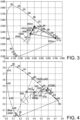
- a light source which can sweep between 440 nm and 465 nm and combine it with a laser emitting at 625 nm then it is possible to make a light source which can produce any color point within the triangle shown in Fig. 2 . Varying the CCT along the BBL may then be possible in the range of about 3000-7000 K.
- Fig. 3 the use of a YAG ceramic is shown with an absorbance of 0.56 at 465 nm and use a light source which can sweep between 440 nm and 465 nm and combined with a laser emitting at 625 nm. It is now possible to make a light source which can produce any color point within the triangle shown in Fig. 3 . This allows e.g. sweeping (of the system light) between about 4800 K and 2200 K.
- Table 1 shows the characteristics of the white light on the BBL at the wavelengths obtained during the scanning: Absorbance Blue nm (fraction %) Red nm (fraction %) YAG fraction % CCT CRI R9 0.42 465 (9) 625 (29) 61 2718 89 73 0.42 445 (21) 625 (6) 73 4655 72 12 0.42 440 (32) 0 68 6906 64 -14 0.56 465 (4) 625 (43) 53 2091 - - 0.56 445 (10) 625 (25) 65 2898 88 95 0.56 440 (20) 625 (7) 73 4438 71 21
- Laser-phosphor based light sources are gathering much interest due to their potential in producing extremely high intensities. There are already products such as car head lights and projectors on the market where lasers are used for pumping phosphor. Laser-phosphor can also be used for other lighting applications. However, for BBL dimming at least a red, a green and a blue individually controllable laser based light sources are needed.
- BBL dimming is herein proposed using (at least) a high frequency wavelength sweeping laser and a ceramic phosphor.
- the high frequency wavelength sweeping laser may be a VCSEL which can be switched between orange light and red light.
- a blue (or green) high frequency wavelength sweeping laser may be used for adjusting the blue (or green) wavelength.
- PWM pulse width modulation
- Fig. 4 schematically depicts several color points that are available with a blue laser at about 450 nm, a green/yellow emitting material with color point at 560 nm and a VCSEL emitting at about orange/red at different wavelengths.
- the white light may have a controllable CCT (substantially along the black body locus).
- the different circles indicate color points that can be chosen in dependence of the centroid wavelength of the wavelength tunable device light, such as a VCSEL (which is by way of example indicated).
- tunable lasers in producing lighting sources with adjustable properties such as (i) the color temperature, (ii) the CRI and/or (iii) the R9 value are suggested. It can also be used for other effects which need to be compensated.
- VCSELs wavelength tunable IR vertical-cavity surface-emitting lasers
- NLO non-linear optical
- Fig.5 schematically depicts spectra of a possible wavelength tunable VCSEL.
- the tunable visible laser light can be used to adjust the color point / color temperature. This can be achieved directly by the tunable visible laser light or indirectly by pumping a phosphor wherein the conversion rate depends on the pump wavelength.
- color separation elements e.g. a dichroic for separating laser beams
- a number of peaks is shown. Intermediate peaks may also be possible.
- level of absorbance from a garnet phosphor at a given wavelength decreases with increasing temperature.
- the color point of the light source changes as a function of light intensity.
- a tunable blue laser can be used for compensating the temperature absorbance and hence keeping the color point of the phosphor with changing temperature.
- a tunable red emitting laser emitting light in a wavelength range from 620 to 675 nm range can be obtained.
- wavelength tunable light sources which are tunable in the IR
- wavelength tunable light sources which are tunable in the visible, may be obtained (see further also below).
- tunable IR emitting lasers in the wavelength range from 900 to 990 nm and 990 to 1140 nm can be used for producing tunable lasers emitting in blue 450-495 nm and green 495-570 nm, respectively.
- Fig. 6 shows a spectrum of a light source comprising a blue laser of 440 nm pumping a YAG:Ce 2% phosphor in combination with red laser light at 610 nm.
- the continuous increasing curve schematically depicts the spectral power distribution of a black body radiator at about 3000 K (see also Fig. 7 ).
- a light generating system 1000 may comprise a first light generating device 110, a second light generating device 120, and a luminescent material 200.
- the first light generating device 110 may be configured to generate first device light 111.
- the second light generating device 120 may be configured to generate second device light 121.
- the first device light 111 and the second device light 121 have different spectral power distributions.
- the luminescent material 200 may be configured to convert at least part of one or more of the first device light 111 and the second device light 121 into luminescent material light 201.
- the luminescent material 200 may comprise a luminescent material of the type A 3 B 5 O 12 :Ce 3+ .
- A may comprise one or more of Y, La, Gd, Tb and Lu, and B may comprise one or more of Al, Ga, In and Sc.
- the light generating system 1000 may comprise a ceramic body 210, and the ceramic body 210 may comprise the luminescent material 200.
- Reference 550 refers to optics, which may e.g. comprise a beam shaping element like a collimator or lens. Other optics, not depicted, may also be possible. Especially, optics 550 refer to optics configured downstream of the first light generating device, the second light generating device, and the luminescent material.
- the light generating system 1000 may further comprise a control system 300 configured to control the system light 1001 in dependence of one or more of an input signal of a user interface, a sensor signal (of a sensor), and a timer, by controlling the first light generating device 110 and the second light generating device 120.
- a control system 300 configured to control the system light 1001 in dependence of one or more of an input signal of a user interface, a sensor signal (of a sensor), and a timer, by controlling the first light generating device 110 and the second light generating device 120.
- the first light generating device 110 may comprise a wavelength variable light generating device configured to generate in an operational mode of the light generating system 1000 first device light 111 changing between at least two centroid wavelengths ( ⁇ 1c,1 , ⁇ 1c,2 ) having a wavelength difference (indicated in the drawing as ⁇ 1c ) of at least 10 nm, with a changing frequency of at least 40 Hz.
- the changing frequency may especially be at least 50 Hz, such as even more especially at least 60 Hz.
- the smallest wavelength band (on the left) may have centroid wavelengths ⁇ 1c,1
- the largest wavelength band (on the right) may have centroid wavelengths ⁇ 1c,2 .
- these at least two centroid wavelengths ⁇ 1c,1 , ⁇ 1c,2 may be indicated as outer centroid wavelengths.
- the light generating system 1000 may be configured to generate in the operational mode of the light generating system 1000 white system light 1001 comprising the luminescent material light 201, and (at least one of) the first device light 111 and the second device light 121.
- the first light generating device 110 may comprise one or more of a vertical cavity surface emitting laser (VCSEL) and a superluminescent diode.
- VCSEL vertical cavity surface emitting laser
- Fig. 8c schematically depicts an embodiment of the absorption (transmission) (left y-axis) and emission (right y-axis) of a luminescent material, wherein the luminescent material is configured to convert part of the first device light having a controllable centroid wavelength (see Fig. 8b ).
- Fig. 8d schematically depicts an embodiment wherein the luminescent material is configured to convert part of the second device light 121. Further, the schematically depicted embodiment is essentially the same as the embodiment schematically depicted in Fig. 8a .
- Fig. 8e schematically depicts an embodiment wherein the second light generating device 120 may comprise a wavelength variable light generating device configured to generate in an operational mode of the light generating system 1000 second device light 121 changing between the at least two centroid wavelengths ( ⁇ 2c,1 , ⁇ 2c,2 ) having a wavelength difference of at least 10 nm, with a changing frequency of at least 40 Hz, especially at least 50 Hz, such as at least 60 Hz.
- Fig. 8f schematically depicts an aspect of possible overlapping (emission) bands.
- the overlapping area is hatched.
- the percentage of overlap is larger for the smaller band than for the larger (here broader) band.
- overlap may especially be defined relative to the smaller emission band.
- the spectral overlap of the smaller emission band by a larger emission band may be less than 20%.
- an emission band may be smaller than another emission band when the spectral power (integrated power) of the former is smaller than of the latter.
- the overlap may be about 50% (of the narrow-band emission)(only about 10% of the broad band emission may overlap with the narrow-band emission).
- the first light generating device 110 may comprise (a) a wavelength variable first light source 10 configured to generate in an operational mode of the light generating system 1000 first light source light 11 changing between the at least two centroid wavelengths ( ⁇ pc,1 , ⁇ pc,2 ) having a wavelength difference of at least 20 nm, with a changing frequency of at least 50 Hz.
- an (first) upconverter material 410 configured downstream of the wavelength variable first light source 10 and configured to convert at least part of the first light source light 11 changing between the at least two centroid wavelengths ( ⁇ pc,1 , ⁇ pc,2 ) into the first device light 111 changing between the at least two centroid wavelengths ( ⁇ 1c,1 , ⁇ 1c,2 ).
- the upconverter material 410 may comprise one or more of an upconverter luminescent material and a frequency doubling material.
- the second light generating device 120 may comprise one or more of a diode laser and a superluminescent diode. In embodiments, the second light generating device 120 may comprise a vertical cavity surface emitting laser (VCSEL).
- VCSEL vertical cavity surface emitting laser
- the second light generating device 120 comprises a second light source 20 configured to generate in an operational mode of the light generating system 1000 second light source light 21 changing between the at least two centroid wavelengths having a wavelength difference of at least 20 nm, with a changing frequency of at least 50 Hz.
- an (second) upconverter material 420 configured downstream of the wavelength variable second light source 20 and configured to convert at least part of the second light source light 21 changing between the at least two centroid wavelengths into the second device light 121 changing between the at least two centroid wavelengths.
- the first light generating device 110 may be configured to generate first device light 111 having a centroid wavelength in the blue wavelength range and the second light generating device 120 may be configured to generate second device light 121 having a centroid wavelength in the red wavelength range.
- the first light generating device 110 may be configured to generate first device light 111 having a centroid wavelength in the red wavelength range and the second light generating device 120 may be configured to generate second device light 121 having a centroid wavelength in the blue wavelength range.
- the first light source 10 may comprise an IR superluminescent diode or IR VCSEL.
- the control system (not depicted, but see e.g. Figs. 8a or 8d )may be configured to control the first light generating device 110 by pulse width modulation. Especially, the control system may be configured to control a spectral power distribution of the system light 1001 in the operational mode by controlling a duty cycle of the first device light 111.
- the wavelength variable light generating device may be configured to generate in the operational mode first pulses of first device light 111 having the centroid wavelength ( ⁇ 1c,1 ) and second pulses of first device light 111 having the centroid wavelength ( ⁇ 1c,2 ), each with a pulse frequency of at least 40 Hz, wherein controlling the spectral power distribution of the system light 1001 in the operational mode may comprise individually controlling a duty cycle of first pules and a duty cycle of the second pulses.
- control system may in embodiments (also) be configured to control the second light generating device by pulse width modulation.
- Fig. 9c examples of pulse width modulation are schematically depicted.
- the two different pulses, indicated with non-hatched and hatched rectangles may refer to pulses of e.g. first device light having centroid wavelengths ⁇ 1c,1 , ⁇ 1c,2 , respectively.
- the light generating device may sweep between two (or more) different spectral power distributions, by which - especially with PWM - the spectral power distribution of the system light may be controlled.
- the control system may be configured to control in an operational mode of the light generating system 1000 the system light 1001 within a correlated color temperature range of 2700-6500 K and having a color rendering index of at least 80.
- Fig. 10 schematically depicts an embodiment of a luminaire 2 comprising the light generating system 1000 as described above.
- Reference 301 indicates a user interface which may be functionally coupled with the control system 300 comprised by or functionally coupled to the light generating system 1000.
- Fig. 10 also schematically depicts an embodiment of lamp 1 comprising the light generating system 1000..
- Fig. 10 schematically depicts embodiments of a lighting device 1200 selected from the group of a lamp 1, a luminaire 2, a projector device, a disinfection device, and an optical wireless communication device, comprising the light generating system 1000 as described herein.
- such lighting device may be a lamp 1, a luminaire 2, a projector device, a disinfection device, or an optical wireless communication device.
- Lighting device light escaping from the lighting device 1200 is indicated with reference 1201.
- Lighting device light 1201 may essentially consist of system light 1001, and may in specific embodiments thus be system light 1001.
- the terms “substantially” or “essentially” herein, and similar terms, will be understood by the person skilled in the art.
- the terms “substantially” or “essentially” may also include embodiments with “entirely”, “completely”, “all”, etc. Hence, in embodiments the adjective substantially or essentially may also be removed.
- the term “substantially” or the term “essentially” may also relate to 90% or higher, such as 95% or higher, especially 99% or higher, even more especially 99.5% or higher, including 100%.
- the invention may provide a combination of a wavelength sweeping laser and a phosphor, and a second laser.
- the wavelength sweeping laser may be a red laser and the second laser a blue laser, and in another embodiment vice versa.
Landscapes
- Physics & Mathematics (AREA)
- Spectroscopy & Molecular Physics (AREA)
- Engineering & Computer Science (AREA)
- General Engineering & Computer Science (AREA)
- Condensed Matter Physics & Semiconductors (AREA)
- General Physics & Mathematics (AREA)
- Electromagnetism (AREA)
- Optics & Photonics (AREA)
- Luminescent Compositions (AREA)
- Circuit Arrangement For Electric Light Sources In General (AREA)
Claims (15)
- Lichterzeugungssystem (1000), umfassend eine erste Lichterzeugungsvorrichtung (110), eine zweite Lichterzeugungsvorrichtung (120) und einen Leuchtstoff (200), wobei:- die erste Lichterzeugungsvorrichtung (110) konfiguriert ist, um erstes Vorrichtungslicht (111) zu erzeugen; die zweite Lichterzeugungsvorrichtung (120) konfiguriert, um zweites Vorrichtungslicht (121) zu erzeugen; wobei das erste Vorrichtungslicht (111) und das zweite Vorrichtungslicht (121) unterschiedliche spektrale Leistungsverteilungen aufweisen;- der Leuchtstoff (200) konfiguriert ist, um mindestens einen Teil von einem oder mehreren des ersten Vorrichtungslichts (111) und des zweiten Vorrichtungslichts (121) in Leuchtstofflicht (201) umzuwandeln;- die erste Lichterzeugungsvorrichtung (110) eine wellenlängenvariable Lichterzeugungsvorrichtung umfasst, die konfiguriert ist, um in einem Betriebsmodus des Lichterzeugungssystems (1000) erstes Vorrichtungslicht (111) zu erzeugen, das zwischen mindestens zwei Schwerpunktwellenlängen (λ1c,1, λ1c,2) wechselt, die einen Wellenlängenunterschied von mindestens 10 nm, mit einer Wechselfrequenz von mindestens 50 Hz, aufweisen; und- das Lichterzeugungssystem (1000) konfiguriert ist, um in dem Betriebsmodus des Lichterzeugungssystems (1000) weißes Systemlicht (1001) zu erzeugen, umfassend das Leuchtstofflicht (201), das erste Vorrichtungslicht (111) und das zweite Vorrichtungslicht (121).
- Lichterzeugungssystem (1000) nach Anspruch 1, wobei die erste Lichterzeugungsvorrichtung (110) eines oder mehrere von einem Vertikalresonatoroberflächenemissionslaser (VCSEL) und einer Superlumineszenzdiode umfasst.
- Lichterzeugungssystem (1000) nach einem der vorstehenden Ansprüche, wobei die erste Lichterzeugungsvorrichtung (110) umfasst (a) eine wellenlängenvariable erste Lichtquelle (10), die konfiguriert ist, um in einem Betriebsmodus des Lichterzeugungssystems (1000) erstes Lichtquellenlicht (11) zu erzeugen, das zwischen den mindestens zwei Schwerpunktwellenlängen (λpc,1, λpc,2) wechselt, die einen Wellenlängenunterschied von mindestens 20 nm, mit einer Wechselfrequenz von mindestens 60 Hz, aufweisen; und (b) ein Aufwärtswandlermaterial (410), das stromabwärts der wellenlängenvariablen ersten Lichtquelle (10) konfiguriert ist und konfiguriert ist, um mindestens einen Teil des Lichtquellenlichts (11), das zwischen den mindestens zwei Schwerpunktwellenlängen (λpc,1, λpc,2) wechselt, in das erste Vorrichtungslicht (111) umzuwandeln, das zwischen den mindestens zwei Schwerpunktwellenlängen (λ1c,1, λ1c,2) wechselt.
- Lichterzeugungssystem (1000) nach Anspruch 3, wobei das Aufwärtswandlermaterial (410) eines oder mehrere von einem Aufwärtswandlerleuchtstoff und einem Frequenzverdopplungsmaterial umfasst.
- Lichterzeugungssystem (1000) nach einem der vorstehenden Ansprüche, wobei der erste Leuchtstoff (200) einen Leuchtstoff von der Art A3B5O12:Ce umfasst, wobei A eines oder mehrere von Y, La, Gd, Tb und Lu umfasst, und wobei B eines oder mehrere von Al, Ga, In und Sc umfasst.
- Lichterzeugungssystem (1000) nach einem der vorstehenden Ansprüche, umfassend einen keramischen Körper (210), wobei der keramische Körper (210) den Leuchtstoff (200) umfasst.
- Lichterzeugungssystem (1000) nach einem der vorstehenden Ansprüche, wobei die zweite Lichterzeugungsvorrichtung (120) eines oder mehrere von einem Diodenlaser und einer Superlumineszenzdiode umfasst.
- Lichterzeugungssystem (1000) nach einem der vorstehenden Ansprüche, wobei die zweite Lichterzeugungsvorrichtung (120) eine wellenlängenvariable Lichterzeugungsvorrichtung umfasst, die konfiguriert ist, um in einem Betriebsmodus des Lichterzeugungssystems (1000) das zweite Vorrichtungslicht (121) zu erzeugen, um zwischen den mindestens zwei Schwerpunktwellenlängen (λ2c,1, λ2c,2) zu wechseln, die einen Wellenlängenunterschied von mindestens 10 nm, mit einer Wechselfrequenz von mindestens 50 Hz, aufweisen.
- Lichterzeugungssystem (1000) nach einem der vorstehenden Ansprüche 1 bis 8, wobei:- die erste Lichterzeugungsvorrichtung (110) konfiguriert ist, um das erste Vorrichtungslicht (111) zu erzeugen, um eine Schwerpunktwellenlänge in dem blauen Wellenlängenbereich aufzuweisen, und wobei die zweite Lichterzeugungsvorrichtung (120) konfiguriert ist, um das zweite Vorrichtungslicht (121) zu erzeugen, um eine Schwerpunktwellenlänge in dem roten Wellenlängenbereich aufzuweisen, oder- die erste Lichterzeugungsvorrichtung (110) konfiguriert ist, um das erste Vorrichtungslicht (111) zu erzeugen, um eine Schwerpunktwellenlänge in dem roten Wellenlängenbereich aufzuweisen, und wobei die zweite Lichterzeugungsvorrichtung (120) konfiguriert ist, um das zweite Vorrichtungslicht (121) zu erzeugen, um eine Schwerpunktwellenlänge in dem blauen Wellenlängenbereich aufzuweisen.
- Lichterzeugungssystem (1000) nach einem der vorstehenden Ansprüche, ferner umfassend ein Steuersystem (300), das konfiguriert ist, um das Systemlicht (1001) in Abhängigkeit von einem oder mehreren zu steuern von einem Eingabesignal einer Benutzerschnittstelle, einem Sensorsignal und einem Zeitgeber, durch ein individuelles Steuern der ersten Lichterzeugungsvorrichtung (110) und der zweiten Lichterzeugungsvorrichtung (120).
- Lichterzeugungssystem (1000) nach Anspruch 10, wobei das Steuersystem (300) konfiguriert ist, um die erste Lichterzeugungsvorrichtung (110) durch Impulsweitenmodulation zu steuern, wobei das Steuersystem konfiguriert ist, um eine spektrale Leistungsverteilung des Systemlichts (1001) in dem Betriebsmodus durch das Steuern eines Arbeitszyklus des ersten Vorrichtungslichts (111) zu steuern.
- Lichterzeugungssystem (1000) nach Anspruch 11, wobei die wellenlängenvariable Lichterzeugungsvorrichtung konfiguriert ist, um in dem Betriebsmodus erste Impulse von erstem Vorrichtungslicht (111) zu erzeugen, das die Schwerpunktwellenlänge (λ1c,1) aufweist, und zweite Impulse von erstem Vorrichtungslicht (111) zu erzeugen, das die Schwerpunktwellenlänge (λ1c,2) aufweist, jeweils mit einer Impulsfrequenz von mindestens 50 Hz, wobei das Steuern der spektralen Leistungsverteilung des Systemlichts (1001) in dem Betriebsmodus das individuelle Steuern eines Arbeitszyklus der ersten Impulse und eines Arbeitszyklus der zweiten Impulse umfasst.
- Lichterzeugungssystem (1000) nach einem der Ansprüche 1 bis 4, 8 oder 10 bis 12, wobei der Leuchtstoff (200) einen Leuchtstoff des Typs A3B5O12:Ce umfasst, wobei A eines oder mehrere umfasst von Y, La, Gd, Tb und Lu, und wobei B eines oder mehrere umfasst von Al, Ga, In und Sc; das Lichterzeugungssystem (1000) umfassend einen keramischen Körper (210), wobei der keramische Körper (210) den Leuchtstoff (200) umfasst; wobei die zweite Lichterzeugungsvorrichtung (120) eines oder mehrere von einem Diodenlaser und einer Superlumineszenzdiode umfasst; wobei die erste Lichterzeugungsvorrichtung (110) konfiguriert ist, um erstes Vorrichtungslicht (111) zu erzeugen, das eine Schwerpunktwellenlänge in dem blauen Wellenlängenbereich aufweist, und wobei die zweite Lichterzeugungsvorrichtung (120) konfiguriert ist, um zweites Vorrichtungslicht (121) zu erzeugen, das eine Schwerpunktwellenlänge in dem roten Wellenlängenbereich aufweist.
- Lichterzeugungssystem (1000) nach einem der vorstehenden Ansprüche, wobei das Steuersystem (300) konfiguriert ist, um in einem Betriebsmodus des Lichterzeugungssystems (1000) das Systemlicht (1001) innerhalb eines korrelierten Farbtemperaturbereichs von 2700-6500 K, und das einen Farbwiedergabeindex von mindestens 80 aufweist, zu steuern.
- Lichterzeugungsvorrichtung (1200), die aus der Gruppe einer Lampe (1), einer Leuchte (2), einer Projektorvorrichtung, einer Desinfektionsvorrichtung und einer optischen drahtlosen Kommunikationsvorrichtung ausgewählt ist, umfassend das Lichterzeugungssystem (1000) nach einem der vorstehenden Ansprüche.
Applications Claiming Priority (2)
| Application Number | Priority Date | Filing Date | Title |
|---|---|---|---|
| EP21196577 | 2021-09-14 | ||
| PCT/EP2022/075291 WO2023041486A1 (en) | 2021-09-14 | 2022-09-12 | Color control using a high frequency wavelength sweeping light source and a phosphor |
Publications (2)
| Publication Number | Publication Date |
|---|---|
| EP4402404A1 EP4402404A1 (de) | 2024-07-24 |
| EP4402404B1 true EP4402404B1 (de) | 2025-03-26 |
Family
ID=77750150
Family Applications (1)
| Application Number | Title | Priority Date | Filing Date |
|---|---|---|---|
| EP22783467.8A Active EP4402404B1 (de) | 2021-09-14 | 2022-09-12 | Farbsteuerung mit einer lichtquelle mit hoher frequenzwellenlänge und einem leuchtstoff |
Country Status (5)
| Country | Link |
|---|---|
| US (1) | US12287088B2 (de) |
| EP (1) | EP4402404B1 (de) |
| JP (1) | JP7625139B2 (de) |
| CN (1) | CN117940701B (de) |
| WO (1) | WO2023041486A1 (de) |
Families Citing this family (1)
| Publication number | Priority date | Publication date | Assignee | Title |
|---|---|---|---|---|
| US12322306B2 (en) * | 2023-11-15 | 2025-06-03 | ROE Visual US, Inc. | RGBCA LED display modules and LED display tiles and LED video displays having the same |
Family Cites Families (30)
| Publication number | Priority date | Publication date | Assignee | Title |
|---|---|---|---|---|
| JPS48102585A (de) * | 1972-04-04 | 1973-12-22 | ||
| AU6034394A (en) * | 1993-02-11 | 1994-08-29 | Louis A. Phares | Controlled lighting system |
| JP2596709B2 (ja) * | 1994-04-06 | 1997-04-02 | 都築 省吾 | 半導体レーザ素子を用いた照明用光源装置 |
| US6350041B1 (en) * | 1999-12-03 | 2002-02-26 | Cree Lighting Company | High output radial dispersing lamp using a solid state light source |
| KR100628264B1 (ko) * | 2002-09-26 | 2006-09-27 | 엘지.필립스 엘시디 주식회사 | 액정표시장치의 백라이트 유닛 |
| US7005679B2 (en) * | 2003-05-01 | 2006-02-28 | Cree, Inc. | Multiple component solid state white light |
| US6807211B1 (en) | 2003-05-27 | 2004-10-19 | Eastman Kodak Company | White-light laser |
| US7982229B2 (en) * | 2004-11-18 | 2011-07-19 | Koninklijke Philips Electronics N.V. | Light emitting device with conversion structure |
| US7316497B2 (en) * | 2005-03-29 | 2008-01-08 | 3M Innovative Properties Company | Fluorescent volume light source |
| CN102160461A (zh) * | 2008-09-17 | 2011-08-17 | 皇家飞利浦电子股份有限公司 | 用于照明房间的照明设备和方法 |
| KR20100126208A (ko) | 2009-05-21 | 2010-12-01 | 조지아 테크 리서치 코포레이션 | 항미생물성 자외선 역변환 조성물 |
| US8884508B2 (en) * | 2011-11-09 | 2014-11-11 | Cree, Inc. | Solid state lighting device including multiple wavelength conversion materials |
| CN104472014B (zh) | 2012-07-18 | 2016-12-07 | 皇家飞利浦有限公司 | 具有混合室和远程磷光体出射窗的可调谐相关色温的基于led的白色光源 |
| CN105765745B (zh) * | 2014-01-28 | 2018-10-23 | 飞利浦照明控股有限公司 | 发光设备 |
| JP2015233127A (ja) | 2014-05-12 | 2015-12-24 | キヤノン株式会社 | 面発光レーザ、レーザアレイ、光源装置、情報取得装置及び光干渉断層計 |
| WO2016037773A2 (en) | 2014-09-11 | 2016-03-17 | Philips Lighting Holding B.V. | Pc-led module with enhanced white rendering and conversion efficiency. |
| US10014448B2 (en) | 2014-10-31 | 2018-07-03 | Koninklijke Philips N.V. | Phosphor converted LED with temperature stable flux and saturated red color point |
| TWI571694B (zh) * | 2014-11-26 | 2017-02-21 | 中強光電股份有限公司 | 照明系統與投影裝置 |
| RU2700375C2 (ru) | 2015-03-19 | 2019-09-16 | Филипс Лайтинг Холдинг Б.В. | Биологическая цветная лампа |
| US20180375003A1 (en) * | 2015-07-02 | 2018-12-27 | Philips Lighting Holding B.V. | Led lamp with slow decay red phosphor resulting in cct variation with light output |
| US10879673B2 (en) | 2015-08-19 | 2020-12-29 | Soraa Laser Diode, Inc. | Integrated white light source using a laser diode and a phosphor in a surface mount device package |
| PL3344918T3 (pl) * | 2015-09-01 | 2020-05-18 | Signify Holding B.V. | System oświetleniowy mięsa ze zwiększoną sprawnością i przesyceniem czerwieni |
| WO2019020395A1 (en) | 2017-07-24 | 2019-01-31 | Lumileds Holding B.V. | VCSEL SET |
| US10222474B1 (en) * | 2017-12-13 | 2019-03-05 | Soraa Laser Diode, Inc. | Lidar systems including a gallium and nitrogen containing laser light source |
| KR102754236B1 (ko) | 2018-05-11 | 2025-01-15 | 엑셀리타스 테크놀로지스 코포레이션 | 기하학적 분리를 이용하는 광학적으로 펌핑된 파장 가변형 수직 공진 표면광 레이저 |
| JP7238294B2 (ja) * | 2018-08-24 | 2023-03-14 | セイコーエプソン株式会社 | 光源装置およびプロジェクター |
| GB2579801B (en) | 2018-12-13 | 2021-04-14 | Exalos Ag | Superluminescent diode module |
| US20200232610A1 (en) | 2019-01-18 | 2020-07-23 | Soraa Laser Diode, Inc. | Laser-based waveguide-coupled white light system for a lighting application |
| US12000552B2 (en) | 2019-01-18 | 2024-06-04 | Kyocera Sld Laser, Inc. | Laser-based fiber-coupled white light system for a vehicle |
| US10912171B1 (en) | 2019-07-31 | 2021-02-02 | Lumileds Llc | Control design for perceptually uniform color tuning |
-
2022
- 2022-09-12 EP EP22783467.8A patent/EP4402404B1/de active Active
- 2022-09-12 JP JP2024516692A patent/JP7625139B2/ja active Active
- 2022-09-12 US US18/691,148 patent/US12287088B2/en active Active
- 2022-09-12 CN CN202280061748.5A patent/CN117940701B/zh active Active
- 2022-09-12 WO PCT/EP2022/075291 patent/WO2023041486A1/en not_active Ceased
Also Published As
| Publication number | Publication date |
|---|---|
| WO2023041486A1 (en) | 2023-03-23 |
| CN117940701A (zh) | 2024-04-26 |
| JP7625139B2 (ja) | 2025-01-31 |
| EP4402404A1 (de) | 2024-07-24 |
| US20240392948A1 (en) | 2024-11-28 |
| CN117940701B (zh) | 2025-12-19 |
| US12287088B2 (en) | 2025-04-29 |
| JP2024535839A (ja) | 2024-10-02 |
Similar Documents
| Publication | Publication Date | Title |
|---|---|---|
| US20240421554A1 (en) | White light source | |
| US12287087B2 (en) | High brightness light source comprising a blue laser pumping a green yellow phosphor and a yellow orange superluminescent diode pumping a red phosphor | |
| US12209746B2 (en) | Laser source tunable white light module | |
| EP4402404B1 (de) | Farbsteuerung mit einer lichtquelle mit hoher frequenzwellenlänge und einem leuchtstoff | |
| EP3999908B1 (de) | Laser-phosphorbasierte lichtquelle mit verbesserter helligkeit | |
| US12398860B2 (en) | High intensity white light source with good uniformity based on a plurality of light sources | |
| EP4469720B1 (de) | Lichtquelle mit hoher helligkeit | |
| US12302463B2 (en) | Color tunable laser based source | |
| US12264790B2 (en) | Integrated solid state light source and phosphor module | |
| US12359794B2 (en) | Heatsink comprising a closed-logo slit for pumping a cylindrical phosphor body | |
| EP4649260A1 (de) | Laser-phosphor-lichtquelle mit verbesserter lebensdauer |
Legal Events
| Date | Code | Title | Description |
|---|---|---|---|
| STAA | Information on the status of an ep patent application or granted ep patent |
Free format text: STATUS: UNKNOWN |
|
| STAA | Information on the status of an ep patent application or granted ep patent |
Free format text: STATUS: THE INTERNATIONAL PUBLICATION HAS BEEN MADE |
|
| PUAI | Public reference made under article 153(3) epc to a published international application that has entered the european phase |
Free format text: ORIGINAL CODE: 0009012 |
|
| STAA | Information on the status of an ep patent application or granted ep patent |
Free format text: STATUS: REQUEST FOR EXAMINATION WAS MADE |
|
| 17P | Request for examination filed |
Effective date: 20240415 |
|
| AK | Designated contracting states |
Kind code of ref document: A1 Designated state(s): AL AT BE BG CH CY CZ DE DK EE ES FI FR GB GR HR HU IE IS IT LI LT LU LV MC MK MT NL NO PL PT RO RS SE SI SK SM TR |
|
| GRAP | Despatch of communication of intention to grant a patent |
Free format text: ORIGINAL CODE: EPIDOSNIGR1 |
|
| STAA | Information on the status of an ep patent application or granted ep patent |
Free format text: STATUS: GRANT OF PATENT IS INTENDED |
|
| DAV | Request for validation of the european patent (deleted) | ||
| DAX | Request for extension of the european patent (deleted) | ||
| INTG | Intention to grant announced |
Effective date: 20241021 |
|
| GRAS | Grant fee paid |
Free format text: ORIGINAL CODE: EPIDOSNIGR3 |
|
| GRAA | (expected) grant |
Free format text: ORIGINAL CODE: 0009210 |
|
| STAA | Information on the status of an ep patent application or granted ep patent |
Free format text: STATUS: THE PATENT HAS BEEN GRANTED |
|
| AK | Designated contracting states |
Kind code of ref document: B1 Designated state(s): AL AT BE BG CH CY CZ DE DK EE ES FI FR GB GR HR HU IE IS IT LI LT LU LV MC MK MT NL NO PL PT RO RS SE SI SK SM TR |
|
| P01 | Opt-out of the competence of the unified patent court (upc) registered |
Free format text: CASE NUMBER: APP_7925/2025 Effective date: 20250217 |
|
| REG | Reference to a national code |
Ref country code: GB Ref legal event code: FG4D |
|
| REG | Reference to a national code |
Ref country code: CH Ref legal event code: EP |
|
| REG | Reference to a national code |
Ref country code: DE Ref legal event code: R096 Ref document number: 602022012357 Country of ref document: DE |
|
| REG | Reference to a national code |
Ref country code: IE Ref legal event code: FG4D |
|
| PG25 | Lapsed in a contracting state [announced via postgrant information from national office to epo] |
Ref country code: RS Free format text: LAPSE BECAUSE OF FAILURE TO SUBMIT A TRANSLATION OF THE DESCRIPTION OR TO PAY THE FEE WITHIN THE PRESCRIBED TIME-LIMIT Effective date: 20250626 |
|
| PG25 | Lapsed in a contracting state [announced via postgrant information from national office to epo] |
Ref country code: FI Free format text: LAPSE BECAUSE OF FAILURE TO SUBMIT A TRANSLATION OF THE DESCRIPTION OR TO PAY THE FEE WITHIN THE PRESCRIBED TIME-LIMIT Effective date: 20250326 |
|
| REG | Reference to a national code |
Ref country code: LT Ref legal event code: MG9D |
|
| PG25 | Lapsed in a contracting state [announced via postgrant information from national office to epo] |
Ref country code: NO Free format text: LAPSE BECAUSE OF FAILURE TO SUBMIT A TRANSLATION OF THE DESCRIPTION OR TO PAY THE FEE WITHIN THE PRESCRIBED TIME-LIMIT Effective date: 20250626 |
|
| PG25 | Lapsed in a contracting state [announced via postgrant information from national office to epo] |
Ref country code: HR Free format text: LAPSE BECAUSE OF FAILURE TO SUBMIT A TRANSLATION OF THE DESCRIPTION OR TO PAY THE FEE WITHIN THE PRESCRIBED TIME-LIMIT Effective date: 20250326 |
|
| PG25 | Lapsed in a contracting state [announced via postgrant information from national office to epo] |
Ref country code: LV Free format text: LAPSE BECAUSE OF FAILURE TO SUBMIT A TRANSLATION OF THE DESCRIPTION OR TO PAY THE FEE WITHIN THE PRESCRIBED TIME-LIMIT Effective date: 20250326 |
|
| PG25 | Lapsed in a contracting state [announced via postgrant information from national office to epo] |
Ref country code: BG Free format text: LAPSE BECAUSE OF FAILURE TO SUBMIT A TRANSLATION OF THE DESCRIPTION OR TO PAY THE FEE WITHIN THE PRESCRIBED TIME-LIMIT Effective date: 20250326 Ref country code: GR Free format text: LAPSE BECAUSE OF FAILURE TO SUBMIT A TRANSLATION OF THE DESCRIPTION OR TO PAY THE FEE WITHIN THE PRESCRIBED TIME-LIMIT Effective date: 20250627 |
|
| REG | Reference to a national code |
Ref country code: NL Ref legal event code: MP Effective date: 20250326 |
|
| PG25 | Lapsed in a contracting state [announced via postgrant information from national office to epo] |
Ref country code: NL Free format text: LAPSE BECAUSE OF FAILURE TO SUBMIT A TRANSLATION OF THE DESCRIPTION OR TO PAY THE FEE WITHIN THE PRESCRIBED TIME-LIMIT Effective date: 20250326 |
|
| PG25 | Lapsed in a contracting state [announced via postgrant information from national office to epo] |
Ref country code: SE Free format text: LAPSE BECAUSE OF FAILURE TO SUBMIT A TRANSLATION OF THE DESCRIPTION OR TO PAY THE FEE WITHIN THE PRESCRIBED TIME-LIMIT Effective date: 20250326 |
|
| REG | Reference to a national code |
Ref country code: AT Ref legal event code: MK05 Ref document number: 1779282 Country of ref document: AT Kind code of ref document: T Effective date: 20250326 |
|
| PG25 | Lapsed in a contracting state [announced via postgrant information from national office to epo] |
Ref country code: SM Free format text: LAPSE BECAUSE OF FAILURE TO SUBMIT A TRANSLATION OF THE DESCRIPTION OR TO PAY THE FEE WITHIN THE PRESCRIBED TIME-LIMIT Effective date: 20250326 |
|
| PG25 | Lapsed in a contracting state [announced via postgrant information from national office to epo] |
Ref country code: ES Free format text: LAPSE BECAUSE OF FAILURE TO SUBMIT A TRANSLATION OF THE DESCRIPTION OR TO PAY THE FEE WITHIN THE PRESCRIBED TIME-LIMIT Effective date: 20250326 Ref country code: PT Free format text: LAPSE BECAUSE OF FAILURE TO SUBMIT A TRANSLATION OF THE DESCRIPTION OR TO PAY THE FEE WITHIN THE PRESCRIBED TIME-LIMIT Effective date: 20250728 |
|
| PG25 | Lapsed in a contracting state [announced via postgrant information from national office to epo] |
Ref country code: IT Free format text: LAPSE BECAUSE OF FAILURE TO SUBMIT A TRANSLATION OF THE DESCRIPTION OR TO PAY THE FEE WITHIN THE PRESCRIBED TIME-LIMIT Effective date: 20250326 Ref country code: PL Free format text: LAPSE BECAUSE OF FAILURE TO SUBMIT A TRANSLATION OF THE DESCRIPTION OR TO PAY THE FEE WITHIN THE PRESCRIBED TIME-LIMIT Effective date: 20250326 |
|
| PG25 | Lapsed in a contracting state [announced via postgrant information from national office to epo] |
Ref country code: AT Free format text: LAPSE BECAUSE OF FAILURE TO SUBMIT A TRANSLATION OF THE DESCRIPTION OR TO PAY THE FEE WITHIN THE PRESCRIBED TIME-LIMIT Effective date: 20250326 |
|
| PGFP | Annual fee paid to national office [announced via postgrant information from national office to epo] |
Ref country code: FR Payment date: 20250925 Year of fee payment: 4 |
|
| PG25 | Lapsed in a contracting state [announced via postgrant information from national office to epo] |
Ref country code: EE Free format text: LAPSE BECAUSE OF FAILURE TO SUBMIT A TRANSLATION OF THE DESCRIPTION OR TO PAY THE FEE WITHIN THE PRESCRIBED TIME-LIMIT Effective date: 20250326 |
|
| PG25 | Lapsed in a contracting state [announced via postgrant information from national office to epo] |
Ref country code: RO Free format text: LAPSE BECAUSE OF FAILURE TO SUBMIT A TRANSLATION OF THE DESCRIPTION OR TO PAY THE FEE WITHIN THE PRESCRIBED TIME-LIMIT Effective date: 20250326 |
|
| PG25 | Lapsed in a contracting state [announced via postgrant information from national office to epo] |
Ref country code: SK Free format text: LAPSE BECAUSE OF FAILURE TO SUBMIT A TRANSLATION OF THE DESCRIPTION OR TO PAY THE FEE WITHIN THE PRESCRIBED TIME-LIMIT Effective date: 20250326 |
|
| PG25 | Lapsed in a contracting state [announced via postgrant information from national office to epo] |
Ref country code: IS Free format text: LAPSE BECAUSE OF FAILURE TO SUBMIT A TRANSLATION OF THE DESCRIPTION OR TO PAY THE FEE WITHIN THE PRESCRIBED TIME-LIMIT Effective date: 20250726 |