EP4401954B1 - Kompaktierungsblock für eine lüftergehäuseform - Google Patents
Kompaktierungsblock für eine lüftergehäuseform Download PDFInfo
- Publication number
- EP4401954B1 EP4401954B1 EP22786058.2A EP22786058A EP4401954B1 EP 4401954 B1 EP4401954 B1 EP 4401954B1 EP 22786058 A EP22786058 A EP 22786058A EP 4401954 B1 EP4401954 B1 EP 4401954B1
- Authority
- EP
- European Patent Office
- Prior art keywords
- mold
- mandrel
- intended
- casing
- manufactured
- Prior art date
- Legal status (The legal status is an assumption and is not a legal conclusion. Google has not performed a legal analysis and makes no representation as to the accuracy of the status listed.)
- Active
Links
Images


Classifications
-
- B—PERFORMING OPERATIONS; TRANSPORTING
- B29—WORKING OF PLASTICS; WORKING OF SUBSTANCES IN A PLASTIC STATE IN GENERAL
- B29C—SHAPING OR JOINING OF PLASTICS; SHAPING OF MATERIAL IN A PLASTIC STATE, NOT OTHERWISE PROVIDED FOR; AFTER-TREATMENT OF THE SHAPED PRODUCTS, e.g. REPAIRING
- B29C70/00—Shaping composites, i.e. plastics material comprising reinforcements, fillers or preformed parts, e.g. inserts
- B29C70/04—Shaping composites, i.e. plastics material comprising reinforcements, fillers or preformed parts, e.g. inserts comprising reinforcements only, e.g. self-reinforcing plastics
- B29C70/28—Shaping operations therefor
- B29C70/40—Shaping or impregnating by compression not applied
- B29C70/42—Shaping or impregnating by compression not applied for producing articles of definite length, i.e. discrete articles
- B29C70/46—Shaping or impregnating by compression not applied for producing articles of definite length, i.e. discrete articles using matched moulds, e.g. for deforming sheet moulding compounds [SMC] or prepregs
- B29C70/48—Shaping or impregnating by compression not applied for producing articles of definite length, i.e. discrete articles using matched moulds, e.g. for deforming sheet moulding compounds [SMC] or prepregs and impregnating the reinforcements in the closed mould, e.g. resin transfer moulding [RTM], e.g. by vacuum
-
- B—PERFORMING OPERATIONS; TRANSPORTING
- B29—WORKING OF PLASTICS; WORKING OF SUBSTANCES IN A PLASTIC STATE IN GENERAL
- B29C—SHAPING OR JOINING OF PLASTICS; SHAPING OF MATERIAL IN A PLASTIC STATE, NOT OTHERWISE PROVIDED FOR; AFTER-TREATMENT OF THE SHAPED PRODUCTS, e.g. REPAIRING
- B29C33/00—Moulds or cores; Details thereof or accessories therefor
- B29C33/30—Mounting, exchanging or centering
- B29C33/306—Exchangeable mould parts, e.g. cassette moulds, mould inserts
-
- B—PERFORMING OPERATIONS; TRANSPORTING
- B29—WORKING OF PLASTICS; WORKING OF SUBSTANCES IN A PLASTIC STATE IN GENERAL
- B29C—SHAPING OR JOINING OF PLASTICS; SHAPING OF MATERIAL IN A PLASTIC STATE, NOT OTHERWISE PROVIDED FOR; AFTER-TREATMENT OF THE SHAPED PRODUCTS, e.g. REPAIRING
- B29C53/00—Shaping by bending, folding, twisting, straightening or flattening; Apparatus therefor
- B29C53/80—Component parts, details or accessories; Auxiliary operations
- B29C53/82—Cores or mandrels
- B29C53/821—Mandrels especially adapted for winding and joining
-
- B—PERFORMING OPERATIONS; TRANSPORTING
- B29—WORKING OF PLASTICS; WORKING OF SUBSTANCES IN A PLASTIC STATE IN GENERAL
- B29C—SHAPING OR JOINING OF PLASTICS; SHAPING OF MATERIAL IN A PLASTIC STATE, NOT OTHERWISE PROVIDED FOR; AFTER-TREATMENT OF THE SHAPED PRODUCTS, e.g. REPAIRING
- B29C70/00—Shaping composites, i.e. plastics material comprising reinforcements, fillers or preformed parts, e.g. inserts
- B29C70/04—Shaping composites, i.e. plastics material comprising reinforcements, fillers or preformed parts, e.g. inserts comprising reinforcements only, e.g. self-reinforcing plastics
- B29C70/28—Shaping operations therefor
- B29C70/40—Shaping or impregnating by compression not applied
- B29C70/42—Shaping or impregnating by compression not applied for producing articles of definite length, i.e. discrete articles
- B29C70/46—Shaping or impregnating by compression not applied for producing articles of definite length, i.e. discrete articles using matched moulds, e.g. for deforming sheet moulding compounds [SMC] or prepregs
- B29C70/462—Moulding structures having an axis of symmetry or at least one channel, e.g. tubular structures, frames
-
- F—MECHANICAL ENGINEERING; LIGHTING; HEATING; WEAPONS; BLASTING
- F01—MACHINES OR ENGINES IN GENERAL; ENGINE PLANTS IN GENERAL; STEAM ENGINES
- F01D—NON-POSITIVE DISPLACEMENT MACHINES OR ENGINES, e.g. STEAM TURBINES
- F01D25/00—Component parts, details, or accessories, not provided for in, or of interest apart from, other groups
- F01D25/005—Selecting particular materials
-
- F—MECHANICAL ENGINEERING; LIGHTING; HEATING; WEAPONS; BLASTING
- F01—MACHINES OR ENGINES IN GENERAL; ENGINE PLANTS IN GENERAL; STEAM ENGINES
- F01D—NON-POSITIVE DISPLACEMENT MACHINES OR ENGINES, e.g. STEAM TURBINES
- F01D25/00—Component parts, details, or accessories, not provided for in, or of interest apart from, other groups
- F01D25/24—Casings; Casing parts, e.g. diaphragms, casing fastenings
- F01D25/243—Flange connections; Bolting arrangements
-
- B—PERFORMING OPERATIONS; TRANSPORTING
- B29—WORKING OF PLASTICS; WORKING OF SUBSTANCES IN A PLASTIC STATE IN GENERAL
- B29L—INDEXING SCHEME ASSOCIATED WITH SUBCLASS B29C, RELATING TO PARTICULAR ARTICLES
- B29L2031/00—Other particular articles
- B29L2031/748—Machines or parts thereof not otherwise provided for
- B29L2031/7504—Turbines
-
- F—MECHANICAL ENGINEERING; LIGHTING; HEATING; WEAPONS; BLASTING
- F05—INDEXING SCHEMES RELATING TO ENGINES OR PUMPS IN VARIOUS SUBCLASSES OF CLASSES F01-F04
- F05D—INDEXING SCHEME FOR ASPECTS RELATING TO NON-POSITIVE-DISPLACEMENT MACHINES OR ENGINES, GAS-TURBINES OR JET-PROPULSION PLANTS
- F05D2300/00—Materials; Properties thereof
- F05D2300/60—Properties or characteristics given to material by treatment or manufacturing
- F05D2300/603—Composites; e.g. fibre-reinforced
Definitions
- the present invention relates to the general field of the manufacture of gas turbine casings, and more particularly to retention casings for gas turbine fans for aircraft engines.
- a fan casing serves several purposes. It defines the air inlet path into the engine, supports an abradable material opposite the fan blade tips, supports a possible sound wave absorption structure for acoustic treatment at the engine inlet, and incorporates or supports a retention shield.
- the latter constitutes a trap that retains debris, such as ingested objects or fragments of damaged blades, projected by centrifugation, in order to prevent them from passing through the casing and reaching other parts of the aircraft.
- wedges are used in particular to compact the flanges of the ends of the preform which are vertical (or radial) and therefore have a different compaction direction from the rest of the preform which has an axial compaction direction. These wedges also make it possible to prevent that by directly placing sectors with a radial closing direction, these same sectors come to bend the flanges or cause them to buckle or shear.
- the compacting wedges are, in the closed position, only in contact with the angular sectors of the counter-mold and the fiber preform, particularly at the level of the future housing fixing flanges.
- the final variability of the positioning of the wedge is very important. This directly influences the final thickness of the part to be manufactured in this area.
- this is an area in which we seek to have good control of the thicknesses because the flanges are then machined. This control is also important to control the quantity of carbon present in the final machined part, i.e. the quantity of injected resin.
- the mold according to the invention thus makes it possible to improve the positioning of the compacting shims.
- the position of the shims is more easily repeatable. Indeed, by having the shims always placed in the same place and resting on one of the plates, the relative positioning of the mold parts will be more precise and it will be easier to maintain a constant compaction force when manufacturing several casings. This then makes it possible to improve the uniformity of the thickness of the parts manufactured by this mold.
- the advantage of reducing the size of the external flange is that, in addition to improving the homogeneity of the thickness of the parts, it can reduce the quantity of resin injected into the mold.
- the mold according to the invention is remarkable in that it makes it possible to reduce the variability of the thicknesses of the final part and to reduce the quantity of resin injected into the mold.
- Yet another subject of the invention according to claim 4 is a gas turbine comprising a fan casing manufactured by a manufacturing method according to the invention.
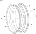
- FIG. 1 represents a perspective view of a fan casing 10 that can be manufactured using a mold and a method according to the invention.
- a casing is centered on a longitudinal axis XX and comprises an annular wall 11 delimited upstream by an upstream flange 12 and downstream by a downstream flange 13 (upstream and downstream being defined relative to the direction of flow of the gas flow in the gas turbine).
- the internal surface 14 of the annular wall 11 is intended to delimit the air inlet vein in the gas turbine.
- FIGS. 2A And 2B represent, schematically and partially, a mold 200 according to the prior art, when it is closed.
- the Figure 2A is a sectional view and the Figure 2B a perspective view of mold 200.
- Such a mold 200 can be used for impregnation by a process of the RTM type (“Resin Transfer Molding”) of a fiber preform 210 in order to manufacture a fan casing 10 such as that presented in Figure 1
- the fibrous preform 210 may be made by three-dimensional weaving of fibers, for example carbon, glass, aramid or ceramic, and the impregnation matrix may be made of polymer, for example epoxide, bismaleimide or polyimide.
- the mold 200 is rotatably mounted on a drive axis (not shown) centered on the X-X axis, and comprises a mandrel 231.
- the mandrel 231 comprises an annular wall taking the form of a barrel on which a fiber preform 210 is intended to be wound, and two lateral flanges (only one flange 230 is shown).
- the mandrel 231 is held on its drive axis by means of spokes not shown.
- the lateral flanges 230 form a support intended to receive the folded parts 211 of the preform 210 wound on the mandrel 231, and which are intended to form the upstream 12 and downstream 13 flanges of the fan casing 10.
- the mold 200 also comprises a counter-mold composed of a plurality of angular sectors 221 assembled in a sealed manner on the mandrel 231, and two compacting wedges 220.
- a counter-mold composed of a plurality of angular sectors 221 assembled in a sealed manner on the mandrel 231, and two compacting wedges 220.
- FIG. 2A only an angular sector 221 with its compacting wedge 220 are represented.
- the compacting wedge 220 is placed between the fiber preform 210 wound on the mandrel 231 and an angular sector 221 of the counter-mold.
- the angular sector 221 bears against the flange 230.
- the compacting wedge 220 has the same height as the future flange 211 of the casing, and therefore does not bear against the flange 230.
- FIG. 3 represents, schematically and partially, a sectional view of a mold 300 according to the invention, when it is closed.
- the mold 300 according to the invention can be used for impregnation by a process of the RTM type (“Resin Transfer Molding”) of a fiber preform 310 in order to manufacture a fan casing 10 such as that presented in Figure 1 .
- RTM Resin Transfer Molding
- the mold 300 is rotatably mounted on a drive axis (not shown) centered on the X-X axis, and comprises a mandrel 331.
- the mandrel 331 comprises an annular wall taking the form of a barrel on which a fiber preform 310 is intended to be wound, and two lateral flanges (only one flange 330 is shown).
- the mandrel 331 is held on its drive axis by means of spokes not shown.
- the lateral flanges 330 form a support intended to receive the folded parts 311 of the preform 310 wound on the mandrel 331, and which are intended to form the upstream 12 and downstream 13 flanges of the fan casing 10.
- the mold 300 also comprises a counter-mold composed of a plurality of angular sectors 321 assembled in a sealed manner on the mandrel 331, and at least one compacting wedge 320.
- the compacting wedge 320 is placed between the fiber preform 310 wound on the mandrel 331 and an angular sector 321 of the counter-mold, and comes to bear against the lateral flange 330.
- the angular sector 321 also bears against the flange 330.
- the compacting wedge 320 is larger than the future flange 311 of the casing so as to cover the top 312 thereof. To do this, it is possible either to use compacting wedges of the same general dimension as the current wedges and to reduce the size of the external flange, or to maintain the size of the external flange and to increase the size of the compacting wedge.
- the relative position of the compacting wedge 320 and the flange 330 is therefore more easily repeatable and thus makes it possible to limit the variability in thickness of the preform 310 during its compaction.
- the step of re-machining the part after compaction and injection of resin into the mold 300 is simplified, or even eliminated.
- the preform 310 is intended to comprise two lateral flanges, it is possible to have two compacting wedges per angular sector, the wedges being intended to cover the top of the two flanges.
- the compacting shims are left in place on the mold after compaction to close the mold and perform an injection
- three compacting shims per angular sector can be used.
- the mold can include three compacting wedges and six angular sectors.
- a fiber preform is first wound onto the mandrel 331 of a mold 300 according to the invention.
- Methods have already been proposed for winding a fiber preform produced for example by three-dimensional weaving around a mandrel 331 such as that of the invention, and will not be described in more detail.
- the mold must be closed to compact the preform.
- the angular sectors must be assembled on the mandrel in a watertight manner and the shim must be placed on one of the side plates so as to cover the top of the future flange of the casing being manufactured.
- the compacting shim is also positioned against a longitudinal face of an angular sector. Thus the shim rests on one of the side plates, and it is simply pushed onto the preform to obtain lower positioning variability, i.e. greater precision.
- the shim placement step is therefore repeated to be able to position the shims against a longitudinal face of an angular sector and place each shim on one of the side plates so that the top of the future flange of the casing being manufactured is covered by the shims.
- the wedges allow compaction in a direction substantially perpendicular to the preform and therefore prevent creases and buckling.
- a polymerizable resin is then injected into the mold by a pressure differential (using an RTM-type process), and the latter is polymerized (by heating or cooling, for example, depending on the nature of the resin used).
- the fan casing thus produced can then be removed from the mold.
Landscapes
- Engineering & Computer Science (AREA)
- Mechanical Engineering (AREA)
- Chemical & Material Sciences (AREA)
- Composite Materials (AREA)
- General Engineering & Computer Science (AREA)
- Materials Engineering (AREA)
- Moulding By Coating Moulds (AREA)
- Structures Of Non-Positive Displacement Pumps (AREA)
- Moulds For Moulding Plastics Or The Like (AREA)
Claims (4)
- Form (300), die bestimmt ist, zur Herstellung eines Gasturbinen-Gebläsegehäuses (10) aus Verbundmaterial verwendet zu werden, umfassend:- einen Kern (331), auf den bestimmt ist, ein Faservorformling (310) des Gebläsegehäuses gewickelt zu werden, der eine ringförmige Wand, deren Profil der Außenfläche dem Profil der Innenfläche (14) des herzustellenden Gehäuses entspricht, und zwei Seitenflansche (330) umfasst, deren Profile denen von Außenflanschen (12, 13) des herzustellenden Gehäuses entsprechen;- eine Vielzahl von Gegenform-Winkelsektoren (321), die dazu bestimmt sind, dicht am Kern angebracht zu werden, und die dazu bestimmt sind, die Form zu schließen und einen auf den Kern gewickelten Faservorformling zu verdichten, und- mindestens einen Verdichtungskeil (320), wobei der Keil dazu bestimmt ist, zwischen dem auf den Kern gewickelten Faservorformling und dem zugehörigen Gegenform-Winkelsektor (321) platziert zu werden,dadurch gekennzeichnet, dass der Verdichtungskeil an einem der Seitenflansche (330) des Kerns anliegt und dazu bestimmt ist, die Spitze (312) eines der äußeren Flansche (311) des herzustellenden Gehäuses zu bedecken.
- Verfahren zum Schließen einer Spritzgussform, die zur Verwendung bei der Herstellung eines Gehäuses für ein Gasturbinengebläse aus Verbundmaterial bestimmt ist, wobei die Form einen Kern umfasst, auf den bestimmt ist, ein Faservorformling des Gebläsegehäuses gewickelt zu werden, wobei der Kern eine ringförmige Wand, deren Profil der Außenfläche dem Profil der Innenfläche des herzustellenden Gehäuses entspricht, und zwei Seitenflansche umfasst, deren Profile denen von Außenflanschen des herzustellenden Gehäuses entsprechen, wobei die Form ebenfalls eine Vielzahl von Gegenform-Winkelsektoren zum Schließen der Form und zum Verdichten des auf den Kern gewickelten Faservorformlings und mindestens einen Verdichtungskeil umfasst, wobei das Verfahren umfasst:- dichtes Verbinden der Gegenform-Sektoren auf dem Kern der Form; und- Platzieren des Verdichtungskeils auf einem der Seitenflansche, wobei der Verdichtungskeil gegen eine Längsseite des zugehörigen Gegenform-Winkelsektors positioniert wird und dazu bestimmt ist, die Spitze eines Außenflansches des herzustellenden Gehäuses zu bedecken.
- Verfahren zur Herstellung eines Gehäuses für ein Gasturbinengebläse aus Verbundmaterial, umfassend:- Wickeln eines Faservorformlings auf den Kern einer Form nach Anspruch 1;- Schließen der Form nach dem Verfahren von Anspruch 2;- Einspritzen eines Harzes in die Form; und- Entformen des Gebläsegehäuses.
- Gasturbine, umfassend ein Gebläsegehäuse (10), das nach einem Verfahren nach Anspruch 3 hergestellt ist.
Applications Claiming Priority (2)
| Application Number | Priority Date | Filing Date | Title |
|---|---|---|---|
| FR2109711A FR3126916B1 (fr) | 2021-09-16 | 2021-09-16 | Cale de compactage d’un moule de carter de soufflante |
| PCT/FR2022/051677 WO2023041861A1 (fr) | 2021-09-16 | 2022-09-06 | Cale de compactage d'un moule de carter de soufflante |
Publications (2)
| Publication Number | Publication Date |
|---|---|
| EP4401954A1 EP4401954A1 (de) | 2024-07-24 |
| EP4401954B1 true EP4401954B1 (de) | 2025-04-09 |
Family
ID=78086558
Family Applications (1)
| Application Number | Title | Priority Date | Filing Date |
|---|---|---|---|
| EP22786058.2A Active EP4401954B1 (de) | 2021-09-16 | 2022-09-06 | Kompaktierungsblock für eine lüftergehäuseform |
Country Status (5)
| Country | Link |
|---|---|
| US (1) | US12172395B2 (de) |
| EP (1) | EP4401954B1 (de) |
| CN (1) | CN118055849B (de) |
| FR (1) | FR3126916B1 (de) |
| WO (1) | WO2023041861A1 (de) |
Families Citing this family (4)
| Publication number | Priority date | Publication date | Assignee | Title |
|---|---|---|---|---|
| FR3151238B1 (fr) * | 2023-07-20 | 2025-06-27 | Safran | Outillage pour le moulage de pièces avec compactage circonférentiel depuis la face externe d’une préforme |
| FR3153556B1 (fr) * | 2023-10-02 | 2025-10-31 | Safran Aircraft Engines | Moule pour la fabrication d’un carter annulaire |
| FR3154342A1 (fr) * | 2023-10-20 | 2025-04-25 | Safran Aircraft Engines | Moule destiné à être utilisé pour la fabrication d'un carter de soufflante et procédé de fabrication d’un carter de soufflante |
| CN119974603A (zh) * | 2025-01-24 | 2025-05-13 | 天津爱思达航天科技股份有限公司 | 一种c型截面带负角的复材支架成型模具及制造方法 |
Family Cites Families (10)
| Publication number | Priority date | Publication date | Assignee | Title |
|---|---|---|---|---|
| FR2913053B1 (fr) | 2007-02-23 | 2009-05-22 | Snecma Sa | Procede de fabrication d'un carter de turbine a gaz en materiau composite et carter ainsi obtenu |
| FR2958875B1 (fr) * | 2010-04-20 | 2017-07-07 | Snecma | Dispositif de fabrication d'un carter en materiau composite et procede de fabrication mettant en oeuvre un tel dispositif |
| FR2961740B1 (fr) * | 2010-06-25 | 2014-03-07 | Snecma | Procede de fabrication d'un article en materiau composite |
| FR2974026B1 (fr) | 2011-04-13 | 2014-09-19 | Snecma | Machine d'enroulement d'une texture fibreuse sur un mandrin d'impregnation |
| FR2981000B1 (fr) * | 2011-10-06 | 2013-11-29 | Snecma | Dispositif pour la fabrication d'une piece en materiau composite |
| FR2981881B1 (fr) | 2011-10-26 | 2013-12-13 | Snecma | Dispositif de maintien d'une texture fibreuse sur un mandrin d'impregnation d'une machine d'enroulement |
| IN2014DN03149A (de) * | 2011-10-26 | 2015-05-22 | Snecma | |
| FR3002750B1 (fr) * | 2013-03-01 | 2015-04-10 | Safran | Moule d'injection pour la fabrication d'une piece de revolution en materiau composite ayant des brides externes, et notamment d'un carter de turbine a gaz |
| FR3044253B1 (fr) * | 2015-11-26 | 2018-05-18 | Safran Aircraft Engines | Moule pour la fabrication d'un carter de soufflante de turbine a gaz en materiau composite et procede de fermeture d'un tel moule |
| US20220347945A1 (en) * | 2021-04-28 | 2022-11-03 | Safran Aircraft Engines | Device for moulding a bladed part of a turbomachine |
-
2021
- 2021-09-16 FR FR2109711A patent/FR3126916B1/fr active Active
-
2022
- 2022-09-06 CN CN202280066417.0A patent/CN118055849B/zh active Active
- 2022-09-06 EP EP22786058.2A patent/EP4401954B1/de active Active
- 2022-09-06 WO PCT/FR2022/051677 patent/WO2023041861A1/fr not_active Ceased
- 2022-09-06 US US18/692,692 patent/US12172395B2/en active Active
Also Published As
| Publication number | Publication date |
|---|---|
| FR3126916B1 (fr) | 2024-05-10 |
| US12172395B2 (en) | 2024-12-24 |
| FR3126916A1 (fr) | 2023-03-17 |
| CN118055849A (zh) | 2024-05-17 |
| US20240262054A1 (en) | 2024-08-08 |
| EP4401954A1 (de) | 2024-07-24 |
| WO2023041861A1 (fr) | 2023-03-23 |
| CN118055849B (zh) | 2025-03-18 |
Similar Documents
| Publication | Publication Date | Title |
|---|---|---|
| EP4401954B1 (de) | Kompaktierungsblock für eine lüftergehäuseform | |
| EP3380294B1 (de) | Form zur herstellung eines aus verbundstoffmaterial hergestellten gasturbinengebläsegehäuses und verfahren zum schliessen solch einer form | |
| EP3183111B1 (de) | Gehäuse aus einem verbundmaterial mit einer selbst-versteiften organischen matrix und verfahren zur herstellung des selben. | |
| EP2707199B1 (de) | Verdichtungs- und spritzgiessform für faservorformling zur herstellung einer turbomaschinen- gleichrichterschaufel aus verbundstoff | |
| EP2961590B1 (de) | Spritzgiesswerkzeug zur herstellung eines rotierenden teils aus einem verbundstoff mit externen flanschen, insbesondere für ein gasturbinengehäuse | |
| EP2560808A1 (de) | Vorrichtung zur herstellung eines gehäuses aus verbundstoff und herstellungsverfahren mit einer derartigen vorrichtung | |
| FR3025248B1 (fr) | Aube de redresseur en materiau composite pour moteur a turbine a gaz et son procede de fabrication | |
| WO2021048486A1 (fr) | Procede de fermeture d'un moule d'injection utilisant des feuillards anti-pincement | |
| EP2585283B1 (de) | Methode zur herstellung eines artikels aus einem verbundwerkstoff | |
| FR3060438A1 (fr) | Procede et outillage de mise en forme d'un carter de soufflante | |
| BE1025628B1 (fr) | Procédé de fabrication de carter composite de compresseur pour turbomachine | |
| WO2016055717A1 (fr) | Procede de demoulage d'un matériau composite à matrice organique | |
| FR3037854A1 (fr) | Procede de fabrication d'un carter de soufflante en materiau composite a panneau abradable integre pour moteur a turbine a gaz et carter ainsi obtenu | |
| EP4132760B1 (de) | Form zur herstellung eines turbinenmotorgebläsegehäuses aus einem verbundstoffmaterial | |
| WO2017121949A1 (fr) | Dispositif de guidage d'une texture fibreuse sur un mandrin d'imprégnation, et mandrin d'imprégnation et machine d'enroulement associés | |
| WO2023037068A1 (fr) | Aube en matériau composite comportant un renfort métallique et procédé de fabrication d'une telle aube | |
| EP4133163B1 (de) | Form zur herstellung eines turbinenmotorgebläsegehäuses aus einem verbundstoffmaterial | |
| FR3146615A1 (fr) | Moule d’injection pour préforme fibreuse avec contre-moules ajustables | |
| EP3877161B1 (de) | Aushärtform zur herstellung einer aus verbundstoffmaterial aus einer vorform gefertigten turbomaschinenkomponente und verfahren zur fertigung einer komponente mittels solch einer form | |
| FR3146614A1 (fr) | Cale de compactage ajustable pour compenser l’usure des moules | |
| EP4161762A1 (de) | Rtm-injektionsverfahren und form mit symmetrischen anti-quetsch-sektoren | |
| FR3154342A1 (fr) | Moule destiné à être utilisé pour la fabrication d'un carter de soufflante et procédé de fabrication d’un carter de soufflante | |
| WO2023203293A1 (fr) | Procede de fabrication d'une aube en materiau composite |
Legal Events
| Date | Code | Title | Description |
|---|---|---|---|
| STAA | Information on the status of an ep patent application or granted ep patent |
Free format text: STATUS: UNKNOWN |
|
| STAA | Information on the status of an ep patent application or granted ep patent |
Free format text: STATUS: THE INTERNATIONAL PUBLICATION HAS BEEN MADE |
|
| PUAI | Public reference made under article 153(3) epc to a published international application that has entered the european phase |
Free format text: ORIGINAL CODE: 0009012 |
|
| STAA | Information on the status of an ep patent application or granted ep patent |
Free format text: STATUS: REQUEST FOR EXAMINATION WAS MADE |
|
| 17P | Request for examination filed |
Effective date: 20240315 |
|
| AK | Designated contracting states |
Kind code of ref document: A1 Designated state(s): AL AT BE BG CH CY CZ DE DK EE ES FI FR GB GR HR HU IE IS IT LI LT LU LV MC MK MT NL NO PL PT RO RS SE SI SK SM TR |
|
| DAV | Request for validation of the european patent (deleted) | ||
| DAX | Request for extension of the european patent (deleted) | ||
| RIC1 | Information provided on ipc code assigned before grant |
Ipc: B29L 31/00 20060101ALN20241213BHEP Ipc: F01D 25/24 20060101ALI20241213BHEP Ipc: F01D 25/00 20060101ALI20241213BHEP Ipc: B29C 33/30 20060101ALI20241213BHEP Ipc: B29C 70/48 20060101ALI20241213BHEP Ipc: B29C 70/46 20060101AFI20241213BHEP |
|
| GRAP | Despatch of communication of intention to grant a patent |
Free format text: ORIGINAL CODE: EPIDOSNIGR1 |
|
| STAA | Information on the status of an ep patent application or granted ep patent |
Free format text: STATUS: GRANT OF PATENT IS INTENDED |
|
| GRAS | Grant fee paid |
Free format text: ORIGINAL CODE: EPIDOSNIGR3 |
|
| INTG | Intention to grant announced |
Effective date: 20250129 |
|
| GRAA | (expected) grant |
Free format text: ORIGINAL CODE: 0009210 |
|
| STAA | Information on the status of an ep patent application or granted ep patent |
Free format text: STATUS: THE PATENT HAS BEEN GRANTED |
|
| AK | Designated contracting states |
Kind code of ref document: B1 Designated state(s): AL AT BE BG CH CY CZ DE DK EE ES FI FR GB GR HR HU IE IS IT LI LT LU LV MC MK MT NL NO PL PT RO RS SE SI SK SM TR |
|
| REG | Reference to a national code |
Ref country code: GB Ref legal event code: FG4D Free format text: NOT ENGLISH |
|
| REG | Reference to a national code |
Ref country code: CH Ref legal event code: EP |
|
| REG | Reference to a national code |
Ref country code: DE Ref legal event code: R096 Ref document number: 602022013034 Country of ref document: DE |
|
| REG | Reference to a national code |
Ref country code: IE Ref legal event code: FG4D Free format text: LANGUAGE OF EP DOCUMENT: FRENCH |
|
| REG | Reference to a national code |
Ref country code: NL Ref legal event code: MP Effective date: 20250409 |
|
| PG25 | Lapsed in a contracting state [announced via postgrant information from national office to epo] |
Ref country code: NL Free format text: LAPSE BECAUSE OF FAILURE TO SUBMIT A TRANSLATION OF THE DESCRIPTION OR TO PAY THE FEE WITHIN THE PRESCRIBED TIME-LIMIT Effective date: 20250409 |
|
| REG | Reference to a national code |
Ref country code: AT Ref legal event code: MK05 Ref document number: 1783191 Country of ref document: AT Kind code of ref document: T Effective date: 20250409 |
|
| PG25 | Lapsed in a contracting state [announced via postgrant information from national office to epo] |
Ref country code: FI Free format text: LAPSE BECAUSE OF FAILURE TO SUBMIT A TRANSLATION OF THE DESCRIPTION OR TO PAY THE FEE WITHIN THE PRESCRIBED TIME-LIMIT Effective date: 20250409 Ref country code: ES Free format text: LAPSE BECAUSE OF FAILURE TO SUBMIT A TRANSLATION OF THE DESCRIPTION OR TO PAY THE FEE WITHIN THE PRESCRIBED TIME-LIMIT Effective date: 20250409 Ref country code: PT Free format text: LAPSE BECAUSE OF FAILURE TO SUBMIT A TRANSLATION OF THE DESCRIPTION OR TO PAY THE FEE WITHIN THE PRESCRIBED TIME-LIMIT Effective date: 20250811 |
|
| PGFP | Annual fee paid to national office [announced via postgrant information from national office to epo] |
Ref country code: DE Payment date: 20250919 Year of fee payment: 4 |
|
| REG | Reference to a national code |
Ref country code: LT Ref legal event code: MG9D |
|
| PG25 | Lapsed in a contracting state [announced via postgrant information from national office to epo] |
Ref country code: GR Free format text: LAPSE BECAUSE OF FAILURE TO SUBMIT A TRANSLATION OF THE DESCRIPTION OR TO PAY THE FEE WITHIN THE PRESCRIBED TIME-LIMIT Effective date: 20250710 Ref country code: NO Free format text: LAPSE BECAUSE OF FAILURE TO SUBMIT A TRANSLATION OF THE DESCRIPTION OR TO PAY THE FEE WITHIN THE PRESCRIBED TIME-LIMIT Effective date: 20250709 |
|
| PG25 | Lapsed in a contracting state [announced via postgrant information from national office to epo] |
Ref country code: PL Free format text: LAPSE BECAUSE OF FAILURE TO SUBMIT A TRANSLATION OF THE DESCRIPTION OR TO PAY THE FEE WITHIN THE PRESCRIBED TIME-LIMIT Effective date: 20250409 |
|
| PG25 | Lapsed in a contracting state [announced via postgrant information from national office to epo] |
Ref country code: BG Free format text: LAPSE BECAUSE OF FAILURE TO SUBMIT A TRANSLATION OF THE DESCRIPTION OR TO PAY THE FEE WITHIN THE PRESCRIBED TIME-LIMIT Effective date: 20250409 |
|
| PG25 | Lapsed in a contracting state [announced via postgrant information from national office to epo] |
Ref country code: HR Free format text: LAPSE BECAUSE OF FAILURE TO SUBMIT A TRANSLATION OF THE DESCRIPTION OR TO PAY THE FEE WITHIN THE PRESCRIBED TIME-LIMIT Effective date: 20250409 |
|
| PG25 | Lapsed in a contracting state [announced via postgrant information from national office to epo] |
Ref country code: AT Free format text: LAPSE BECAUSE OF FAILURE TO SUBMIT A TRANSLATION OF THE DESCRIPTION OR TO PAY THE FEE WITHIN THE PRESCRIBED TIME-LIMIT Effective date: 20250409 |
|
| PGFP | Annual fee paid to national office [announced via postgrant information from national office to epo] |
Ref country code: FR Payment date: 20250923 Year of fee payment: 4 |
|
| PG25 | Lapsed in a contracting state [announced via postgrant information from national office to epo] |
Ref country code: RS Free format text: LAPSE BECAUSE OF FAILURE TO SUBMIT A TRANSLATION OF THE DESCRIPTION OR TO PAY THE FEE WITHIN THE PRESCRIBED TIME-LIMIT Effective date: 20250709 |
|
| PG25 | Lapsed in a contracting state [announced via postgrant information from national office to epo] |
Ref country code: IS Free format text: LAPSE BECAUSE OF FAILURE TO SUBMIT A TRANSLATION OF THE DESCRIPTION OR TO PAY THE FEE WITHIN THE PRESCRIBED TIME-LIMIT Effective date: 20250809 |
|
| PG25 | Lapsed in a contracting state [announced via postgrant information from national office to epo] |
Ref country code: LV Free format text: LAPSE BECAUSE OF FAILURE TO SUBMIT A TRANSLATION OF THE DESCRIPTION OR TO PAY THE FEE WITHIN THE PRESCRIBED TIME-LIMIT Effective date: 20250409 |