EP4401501A1 - Steuerungsvorrichtung, steuerungsverfahren und programm - Google Patents
Steuerungsvorrichtung, steuerungsverfahren und programm Download PDFInfo
- Publication number
- EP4401501A1 EP4401501A1 EP22867151.7A EP22867151A EP4401501A1 EP 4401501 A1 EP4401501 A1 EP 4401501A1 EP 22867151 A EP22867151 A EP 22867151A EP 4401501 A1 EP4401501 A1 EP 4401501A1
- Authority
- EP
- European Patent Office
- Prior art keywords
- control device
- display
- reception
- identification signal
- control
- Prior art date
- Legal status (The legal status is an assumption and is not a legal conclusion. Google has not performed a legal analysis and makes no representation as to the accuracy of the status listed.)
- Pending
Links
Images


Classifications
-
- H—ELECTRICITY
- H04—ELECTRIC COMMUNICATION TECHNIQUE
- H04W—WIRELESS COMMUNICATION NETWORKS
- H04W4/00—Services specially adapted for wireless communication networks; Facilities therefor
- H04W4/80—Services using short range communication, e.g. near-field communication [NFC], radio-frequency identification [RFID] or low energy communication
-
- H—ELECTRICITY
- H04—ELECTRIC COMMUNICATION TECHNIQUE
- H04W—WIRELESS COMMUNICATION NETWORKS
- H04W76/00—Connection management
- H04W76/10—Connection setup
- H04W76/11—Allocation or use of connection identifiers
-
- G—PHYSICS
- G08—SIGNALLING
- G08C—TRANSMISSION SYSTEMS FOR MEASURED VALUES, CONTROL OR SIMILAR SIGNALS
- G08C17/00—Arrangements for transmitting signals characterised by the use of a wireless electrical link
- G08C17/02—Arrangements for transmitting signals characterised by the use of a wireless electrical link using a radio link
-
- H—ELECTRICITY
- H04—ELECTRIC COMMUNICATION TECHNIQUE
- H04W—WIRELESS COMMUNICATION NETWORKS
- H04W12/00—Security arrangements; Authentication; Protecting privacy or anonymity
- H04W12/06—Authentication
-
- H—ELECTRICITY
- H04—ELECTRIC COMMUNICATION TECHNIQUE
- H04W—WIRELESS COMMUNICATION NETWORKS
- H04W4/00—Services specially adapted for wireless communication networks; Facilities therefor
- H04W4/50—Service provisioning or reconfiguring
-
- H—ELECTRICITY
- H04—ELECTRIC COMMUNICATION TECHNIQUE
- H04W—WIRELESS COMMUNICATION NETWORKS
- H04W76/00—Connection management
- H04W76/10—Connection setup
-
- H—ELECTRICITY
- H04—ELECTRIC COMMUNICATION TECHNIQUE
- H04W—WIRELESS COMMUNICATION NETWORKS
- H04W84/00—Network topologies
- H04W84/02—Hierarchically pre-organised networks, e.g. paging networks, cellular networks, WLAN [Wireless Local Area Network] or WLL [Wireless Local Loop]
- H04W84/10—Small scale networks; Flat hierarchical networks
- H04W84/12—WLAN [Wireless Local Area Networks]
Definitions
- the present disclosure relates to a control device, a control method, and a program.
- Patent Literature (PTL) 1 discloses a system in which connection information is input using a terminal when an apparatus (device) is connected to an access point through wireless communication.
- the present disclosure provides a control device enabling early finding of an apparatus that performs wireless communication.
- the control device is a control device including: a wireless interface that (a) performs wireless communication through one channel selected from N channels where N is an integer of 2 or more, and (b) when not performing the wireless communication, waits for reception of an identification signal to be transmitted by an apparatus while scanning the N channels, and receives the identification signal; and a provider that refers to the identification signal received by the wireless interface, communicably connects to the apparatus, and provides setting information of the apparatus to the apparatus.
- a transmission channel through which the apparatus transmits the identification signal is predetermined, and a proportion of a time or number of times to wait for reception in the transmission channel in a total duration of the scanning by the wireless interface is greater than 1/N.
- the control device enables early finding of an apparatus that performs wireless communication.
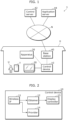
- FIG. 1 is a block diagram schematically illustrating the configuration of control system 1 according to the present embodiment.
- Control system 1 is a system that promotes installation of software to terminal T, the software managing apparatus 30 disposed in residence H of user U.
- control system 1 includes control device 10, display device 20, control server 42, and application server 44.
- Control system 1 may further include apparatus 30 and base station 40.
- Apparatus 30 is an apparatus managed by the software installed on terminal T, and is, for example, a home appliance, and more specifically, is a laundry machine, an air conditioner, a refrigerator, a microwave oven, a television receiver (also referred to as television), a recording apparatus, or a front-door intercom.
- Apparatus 30 can be a non-display-control apparatus or a display-control apparatus.
- the non-display-control apparatus is an apparatus that is neither an apparatus including a display device nor an apparatus that is connected to a display device and displays an image on a display screen included in the display device.
- the display-control apparatus is an apparatus including a display device or an apparatus that is connected to a display device and displays an image on a display screen included in the display device.
- apparatus 30 is an apparatus newly disposed in residence H by user U, and more specifically an apparatus that user U newly bought for use in residence H.
- Base station 40 is a wireless LAN base station inside residence H of user U.
- the wireless LAN is a Wi-Fi (registered trademark) network, for example. This case will be described as one example, but any other configuration can be used.
- Display device 20 is a display device including a display screen. Display device 20 displays an image on the display screen in response to control by control device 10.
- Control server 42 is a server apparatus that provides information to promote installation of the software operating on terminal T to terminal T.
- Control server 42 is implemented by a computer.
- Application server 44 is a server apparatus that has software operating on terminal T (generally, also referred to application software or a smartphone application. Application server 44 is implemented by a computer.
- Control device 10 is a control device that promotes installation of software to terminal T, the software being software that manages apparatus 30 and operates on terminal T.
- Control device 10 is connected to base station 40 through wireless communication, and is connected to network N through base station 40 to be communicable with other apparatuses connected network N.
- Control device 10 controls display of an image on the display screen included in display device 20.
- Control device 10 is a recording apparatus, for example, and this case will be described as one example.
- control device 10 controls display of an image on the display screen included in display device 20 (such as a television) connected to the recording apparatus with a video communication standard (HDMI (registered trademark)).
- HDMI registered trademark
- Control device 10 may include display device 20. In this case, it can be said that control device 10 includes a display screen. Control device 10 controls display of an image on the display screen included in control device 10. Control device 10 may be a television, for example.
- FIG. 2 is a block diagram illustrating a functional configuration of control device 10 according to the present embodiment.
- control device 10 includes wireless interface (wireless IF) 11, obtainer 12, display controller 13, and provider 14.
- wireless IF wireless interface
- Wireless IF 11 is a communication interface which performs wireless communication, and includes an antenna and a wireless circuit. Wireless IF 11 receives an identification signal wirelessly transmitted by apparatus 30. Wireless IF 11 is also referred to as first wireless interface.
- wireless IF 11 may receive the identification signal as a service set identifier (SSID) included in a beacon signal of the wireless LAN (specifically, Wi-Fi network).
- SSID service set identifier
- the identification signal may be included in the SSID. This case will be described as one example, but any other configuration can be used.
- Wireless IF 11 performs wireless communication through one channel selected from N (where N is an integer of 2 or more) communication channels (also simply referred to as channels), and when not performing wireless communication, wireless IF 11 waits for reception of the identification signal to be transmitted by apparatus 30 while scanning N channels, and receives the identification signal.
- N is an integer of 2 or more communication channels
- wireless IF 11 waits for reception of the identification signal to be transmitted by apparatus 30 while scanning N channels, and receives the identification signal.
- the transmission channel as a channel through which apparatus 30 transmits the identification signal is predetermined, the proportion of the time or the number of times to wait for reception in the transmission channel in the total duration of the scanning by wireless IF 11 is greater than 1/N.
- the time to wait for reception in the transmission channel in the scanning by wireless IF 11 may be the longest among the times to wait for reception in the N channels, or the number of times to wait for reception in the transmission channel in the scanning by wireless IF 11 may be the largest among the numbers of times to wait for reception in the N channels.
- wireless IF 11 may alternately wait for reception in the transmission channel and in any channel of a plurality of channels excluding the transmission channel.
- Wireless IF 11 may further include a wireless interface for near-field wireless communication.
- the communication standard for near-field wireless communication is, for example, Bluetooth (registered trademark) Low Energy (BLE), and this case will be described as one example.
- BLE communication interface included in wireless IF 11 can be used when apparatus 30 is a display-control apparatus. In this case, wireless IF 11 may receive the identification signal as information included in the beacon signal in the BLE network.
- Obtainer 12 is a functional portion that obtains information from control server 42.
- the functional portion included in control device 10 can be implemented by a processor included in control device 10 (such as a central processing unit (CPU)) (not illustrated), the processor executing a predetermined program using a memory (not illustrated). The same is applied to functional portions thereafter.
- a processor included in control device 10 such as a central processing unit (CPU)
- CPU central processing unit
- obtainer 12 refers to the identification signal received by wireless IF 11, and obtains information indicating that the software that manages apparatus 30 and operates on terminal T can be installed on terminal T.
- the information may include notification information indicating that the software can be installed on terminal T, or the address of the site which provides the software.
- the site is a web site written in hyper text markup language (HTML), for example, but not limited thereto.
- the information may include, for example, an image which indicates the address (or uniform resource locator (URL)) of the site providing the software and is readable by terminal T.
- the image is, for example, a two-dimensional code in which the address is encoded, and more specifically, is a QR code (registered trademark).
- Display controller 13 is a functional portion that controls display of an image (also referred to as presentation image) on the display screen of display device 20.
- Display controller 13 obtains the presentation image from control server 42, and controls the display of the obtained presentation image.
- control device 10 includes display device 20 (in other words, control device 10 includes the display screen)
- display controller 13 controls the display of the presentation image on the display screen included in control device 10.
- control device 10 is connected to display device 20
- display controller 13 controls the display of the presentation image on the display screen included in display device 20 connected to control device 10.
- Display controller 13 performs the control by providing a video signal to display device 20, the video signal indicating the image to be displayed on the display screen.
- Display device 20 to which the video signal is provided displays the presentation image on the display screen based on the provided video signal.
- Provider 14 is a functional portion that provides information to apparatus 30.
- Provider 14 provides connection information for apparatus 30 to connect to base station 40 (in other words, connection information for apparatus 30 to connect to the wireless LAN).
- Provider 14 provides connection information to terminal T, the connection information being connection information for wireless IF 11 to connect to base station 40 and being set in wireless IF 11.
- Software for managing apparatus 30 is installed in terminal T. It is assumed that terminal T to which the connection information is provided provides the provided connection information to apparatus 30 in response to the operation of the software. Thus, provider 14 provides the connection information to apparatus 30 through terminal T.
- provider 14 may convert the connection information according to predetermined conversion rules, and then provide the converted connection information to apparatus 30 through terminal T. Specifically, according to the predetermined conversion rules, provider 14 may convert the connection information set in wireless IF 11 to connection information in accordance with the communication standard of a wireless IF (second wireless interface) included in apparatus 30. In this case, provider 14 sets the converted connection information in wireless IF 11, and determines whether wireless IF 11 in which the connection information is set is successfully connected to base station 40. Then, when provider 14 determines that wireless IF 11 is successfully connected to base station 40, provider 14 provides the converted connection information to apparatus 30 through terminal T.
- predetermined conversion rules provider 14 may convert the connection information set in wireless IF 11 to connection information in accordance with the communication standard of a wireless IF (second wireless interface) included in apparatus 30. In this case, provider 14 sets the converted connection information in wireless IF 11, and determines whether wireless IF 11 in which the connection information is set is successfully connected to base station 40. Then, when provider 14 determines that wireless IF 11 is successfully connected to base
- the predetermined conversion rules are conversion rules for IDs of the wireless LANs whose communication standards are different from each other, and more specifically, are conversion rules for converting the SSID of the Wi-Fi network as the wireless LAN to those in IEEE802.11a and IEEE802.11g.
- the conversion rules will be described in detail later.
- provider 14 communicably connects to apparatus 30, and provides setting information or position information needed for the operation of apparatus 30 to apparatus 30.
- the identification signal transmitted by apparatus 30 may include type information indicating the type of apparatus 30. This case is described as one example.
- the type information includes at least information indicating that the type of apparatus 30 is a non-display-control apparatus or a display-control apparatus.
- the identification signal includes the type information and the type information indicates that apparatus 30 is a non-display-control apparatus
- obtainer 12 obtains the above-mentioned information.
- display controller 13 controls the display of the image.
- provider 14 When the type information included in the identification signal indicates that apparatus 30 is a display-control apparatus, provider 14 provides the setting information to apparatus 30.
- the identification signal When the identification signal is included in the SSID, for example, information (such as numerals, characters, or symbols) in a predetermined position within the SSID is used as the identification signal, and the information in the predetermined position in the identification signal is used as the type information.
- Obtainer 12 obtains the type information by extracting the information in the predetermined position in the identification signal.
- the identification signal may further include the category (the type such as a laundry machine, an air conditioner, a refrigerator, a microwave oven, a television, or a recording apparatus) or version information of apparatus 30.
- the information such as numerals, characters, or symbols
- Obtainer 12 obtains the product category and the version information by extracting the information in the predetermined position in the identification signal.
- control device 10 having such a configuration above will be described in detail.
- FIG. 3 is a flowchart illustrating processing to be executed by control device 10 according to the present embodiment.
- the flowchart illustrated in FIG. 3 represents a flow of processing from finding of apparatus 30 by control device 10 to execution of the processing related to apparatus 30 according to the type of apparatus 30 found.
- the flowchart illustrated in FIG. 3 may be repeatedly executed by control device 10.
- step S101 wireless IF 11 in control device 10 waits for reception of the beacon while scanning the channels, and receives the beacon. It is assumed that this beacon is the beacon transmitted by apparatus 30. For example, apparatus 30 transmits the beacon at a predetermined interval (e.g., an interval of 100 milliseconds) for a predetermined time (e.g., for 15 minutes) after the power supply is turned on.
- a predetermined interval e.g., an interval of 100 milliseconds
- a predetermined time e.g., for 15 minutes
- step S102 obtainer 12 in control device 10 extracts the type information included in the beacon received in step S101, and obtains the type of apparatus 30 that transmits the beacon.
- step S103 obtainer 12 in control device 10 determines whether the type of apparatus 30 obtained in step S102 is a display-control apparatus. When it is determined that the type of apparatus 30 is a display-control apparatus (Yes in step S103), the processing goes to step S111. If it is not the case (No in step S103), the processing goes to step S104.
- control device 10 executes the processing related to the non-display-control apparatus.
- the detailed processing included in step S104 will be described later.
- control device 10 executes the processing related to the display-control apparatus.
- the detailed processing included in step S111 will be described later.
- step S104 or step S111 is completed, a series of processings illustrated in FIG. 3 is terminated.
- control device 10 executes the processing related to the type according to whether apparatus 30 is a display-control apparatus or a non-display-control apparatus.
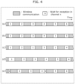
- FIG. 4 is a diagram illustrating a method of scanning channels by control device 10 according to the present embodiment.
- the scanning method illustrated in FIG. 4 can be used when control device 10 receives the beacon (see step S101 in FIG. 3 ).
- wireless IF 11 has 1 to 13 communicable channels and the number N of channels is 13 will be described as one example.
- the transmission channel that is the channel through which apparatus 30 transmits the identification signal is defined as channel 1.
- FIG. 4 indicates one example of the method of scanning by a control device in Comparative Example, and (b) to (e) indicate the methods of scanning by control device 10.
- the abscissa represents time.
- hatched rectangles each indicate a period during which wireless communication is performed (also referred to as communication period)
- non-hatched rectangles with a numeric value each indicate a period of reception (reception period) in the channel indicated by the numeric value.
- the control device performs wireless communication in the communication period, and waits for reception in the reception period during which the control device does not perform wireless communication.
- the scanning method according to Comparative Example illustrated in (a) of FIG. 4 is different from the scanning method by control device 10, and is executed by a standard wireless communication apparatus.
- the control device sequentially waits for reception in each of the communicable channels, such as channels 1, 2, ... After waiting for reception in channel 13 is completed, the control device again waits for reception from channel 1.
- the control device can wait for reception in the channels in any order. In this case, the proportion of the time to wait for reception in channel 1 in the total duration of the scanning is 1/13, and the proportion of the number of times to wait for reception in channel 1 in the total duration of the scanning is 1/13.
- control device 10 sequentially waits for reception in channels 1, 2, 3, and 4 in a plurality of reception periods, and thereafter waits for reception in channel 1 as the transmission channel. Then, control device 10 sequentially waits for reception in channel 5 and thereafter.
- the proportion of the time to wait for reception in channel 1 in the total duration of the scanning is 1/5, and is greater than 1/13.
- the proportion of the number of times to wait for reception in channel 1 in the total duration of the scanning is 1/5, and is greater than 1/13.
- control device 10 alternately waits for reception in channel 1 and the channels excluding channel 1 in a plurality of reception periods.
- the order of the channels excluding channel 1 can be any order.
- the proportion of the time to wait for reception in channel 1 in the total duration of the scanning is 1/2, and is greater than 1/13.
- the proportion of the number of times to wait for reception in channel 1 in the total duration of the scanning is 1/2, and is greater than 1/13.
- control device 10 waits for reception in channel 1 for a longer time than the time to wait for reception in the channels excluding channel 1.
- the time to wait for reception in channel 1 is set 1.5 times longer than the time to wait for reception in the channels excluding channel 1.
- the proportion of the time to wait for reception in channel 1 in the total duration of the scanning is 1.5/13, and is greater than 1/13.
- the proportion of the number of times to wait for reception in channel 1 in the total duration of the scanning is equal to 1/13.
- control device 10 waits for reception in channel 1 multiple times (e.g., two times) in scanning in which control device 10 waits for reception in channel 1, 2, ..., 13.
- Control device 10 waits for reception in channel 1 for a half time of the time to wait for reception in the case of (a) or the like in a first period of waiting for reception, and then waits for reception in channel 1 for a half time of the time to wait for reception in the case of (a) or the like immediately after waiting for reception in channel 4.
- the proportion of the time to wait for reception in channel 1 in the total duration of the scanning is equal to 1/13.
- the proportion of the number of times to wait for reception in channel 1 in the total duration of the scanning is 2/13, and is greater than 1/13.
- the proportion of the time or the number of times to wait for reception in the transmission channel in the total duration of the scanning is greater than 1/N.
- the processing related to the non-display-control apparatus to be executed by control device 10 includes processing to install software to terminal T, the software managing apparatus 30 which is a non-display-control apparatus.
- FIG. 5 is a flowchart illustrating processing related to the non-display-control apparatus to be executed by control device 10 according to the present embodiment.
- the processing illustrated in FIG. 5 illustrates details of the processing included in step S104 of FIG. 3 .
- step S201 display controller 13 in control device 10 transmits the type of apparatus 30 to control server 42.
- Control server 42 receives the type of apparatus 30.
- the type of apparatus 30 includes at least information indicating that apparatus 30 is a non-display-control apparatus, and may further include the class or model of apparatus 30.
- step S202 display controller 13 in control device 10 obtains a presentation image from control server 42.
- the presentation image to be obtained is transmitted by control server 42 that has received the type of apparatus 30 transmitted in step S201, in response to the reception.
- the presentation image obtained in step S202 may be a presentation image prepared according to the class or model of apparatus 30.
- step S203 display controller 13 in control device 10 displays the presentation image, which is obtained in step S202, on the display screen. It is assumed that the displayed presentation image is viewed by user U.
- control device 10 can display the presentation image for installing software on the display screen, the software managing apparatus 30 that is a non-display-control apparatus.
- FIG. 6 is a diagram illustrating a first example of the image to be displayed by control device 10 according to the present embodiment.
- Image 50 illustrated in FIG. 6 is one example of the image displayed by display device 20 by control of control device 10, and includes a list of recorded programs. Image 50 may be a different image as long as it is an image displayed in the normal operation of control device 10 that is a recording apparatus.
- Image 50 includes image 51 that is a presentation image.
- Image 51 is one example of the information indicating that the software that manages apparatus 30 (e.g., laundry machine) and operates on terminal T can be used (or installed) in terminal T. It can also be said that image 51 is superimposed and displayed on image 50.
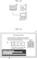
- FIG. 7 is a diagram illustrating second example of the image displayed by control device 10 according to the present embodiment.
- Image 55 illustrated in FIG. 7 is one example of the image displayed by display device 20 by control of control device 10, and includes image 56 that is a presentation image including a two-dimensional code (specifically, QR code (registered trademark)) indicating the address of the site that provides the software.
- QR code registered trademark
- the two-dimensional code in image 56 is the address of the site encoded by a predetermined encoding method, the site providing the software that operates on terminal T.
- Terminal T can obtain the address of the site by capturing image 56 with a camera based on an operation by user U and decoding the two-dimensional code in image 56 by a predetermined decode method, and can access to the site.
- image 55 may include information indicating that connection of apparatus 30 to a network is convenient, in other words, information that motivates user U to connect apparatus 30 to the network.
- FIG. 8 is a sequence diagram illustrating processing related to the non-display-control apparatus to be executed by control system 1 according to the present embodiment.
- step S301 apparatus 30 transmits a beacon.
- Apparatus 30 can repeatedly transmit the beacon at a predetermined time interval (e.g., an interval of 100 milliseconds).
- the beacon transmitted in step S301 can be one of the beacons repeatedly transmitted.
- control device 10 waits for reception of the beacon.
- the waiting for reception of the beacon is performed by scan of the channels (see (b) to (e) in FIG. 4 ).
- step S303 in waiting for reception of the beacon, control device 10 receives the beacon transmitted by apparatus 30 in step S301.
- Step S303 corresponds to step S101 in FIG. 3 .
- control device 10 transmits the type of apparatus 30 to control server 42.
- the type of apparatus 30 is transmitted based on determination that the type of apparatus 30 determined by the beacon transmitted by apparatus 30 is not the display-control apparatus.
- Step S304 corresponds to steps S102, S103, and S104 in FIG. 3 and step S201 in FIG. 5 .
- control server 42 determines the timing at which the presentation image is displayed on the display screen.
- the timing at which the presentation image is displayed may be any number of times as long as it is more than or equal to one time, and may be at any time. For example, it may be a timing immediately after step S304, or may be a predetermined time of day.
- step S306 control server 42 determines whether the timing determined in step S305 has come. When it is determined that the timing has come (Yes in step S306), the processing goes to step S307. When it is not the case (No in step S306), the processing goes to step S306. In other words, control server 42 waits in step S306 until the timing comes. When a plurality of timings are determined in step S305, step S306 is executed at each of the timings. When a notification (step S312 described later) that an application is installed on terminal T is received, execution of step S306 is unnecessary at the timings thereafter.
- control server 42 transmits a presentation image to control device 10.
- Control device 10 receives the transmitted presentation image.
- control device 10 displays the presentation image received in step S307 on the display screen.
- the presentation image includes a QR code (registered trademark) in which at least the address of the site in application server 44 is encoded. It is assumed that the displayed presentation image is viewed by user U.
- terminal T obtains the address of the site in application server 44 by capturing the QR code (registered trademark) included in the presentation image based on an operation by user U who has viewed the presentation image displayed in step S308, and decoding the QR code (registered trademark).
- QR code registered trademark
- step S310 terminal T transmits a request to obtain the application to the address obtained in step S309.
- Application server 44 receives the transmitted request to obtain the application.
- step S311 in response to the request received in step S310, application server 44 transmits the application as the target of the request to terminal T. Terminal T receives or downloads the transmitted application.
- step S312 the application received in step S311 is installed on terminal T.
- Terminal T may transmit a notification to control server 42, the notification indicating that the application is installed. Transmission of the presentation image by control server 42 (step S307) after the notification can be stopped by the notification.
- control device 10 transmits connection information to terminal T, the connection information being used for connection of apparatus 30 to the wireless LAN.
- Terminal T transmits the received connection information to apparatus 30.
- the connection information transmitted by control device 10 is provided to apparatus 30 through terminal T.
- Control device 10 may provide the connection information as it is to apparatus 30, the connection information being used for connection of apparatus 30 to the wireless LAN, or may convert the connection information according to predetermined conversion rules and provide the converted connection information to apparatus 30 (described later).
- Step S313 need not be executed.
- terminal T can control device 30 by operating the application installed in step S312.
- the information may be provided from terminal T to apparatus 30 through near-field wireless communication, or may be provided through network N when apparatus 30 is connected to wireless LAN through step S313.
- the transmission and display of the presentation image in steps S307 and S308 may be performed one time or two or more times.
- image 56 illustrated in FIG. 7 is used as the presentation image in the one-time transmission and display of the presentation image.
- image 51 illustrated in FIG. 6 may be used as the presentation image
- image 56 illustrated in FIG. 7 may be used as the presentation image.
- the predetermined time of day to be used in step S305 can be a predicted time at which user U is not relatively busy, or can be a predicted time (e.g., 20:00) at which user U can ensure the time to install the software to terminal T. This leads to an advantage of increasing a probability that user U installs the software to terminal T using the presentation image.
- a wireless interface connectable to base station 40 through a wireless LAN is provided in the apparatus used in residence H.
- Examples of communication standards for the wireless LAN include IEEE802.11a and IEEE802.11g.
- IEEE802.11a has features such as a high relatively high communication rate, communication loss likely to be caused by influences from obstacles present in a communication path, and relatively high cost of the communication interface.
- IEEE802.11g has features such as relatively small influences from obstacles present in a communication path, relatively low cost of the communication interface, and communication loss likely to be caused by influences from radiowaves radiated by a microwave oven or the like.
- apparatuses such as a television and a recording apparatus used in applications to video transmission required for a relatively high communication rate, for example, may include a communication interface for IEEE802.11a in some cases.
- Apparatuses such as a laundry machine, an air conditioner, a refrigerator, and a microwave oven used in applications where a relatively high communication rate is not required, for example, may include a communication interface for IEEE802.11g in some cases.
- control device 10 may include a communication interface for IEEE802.11a in some cases.
- Apparatus 30 may include a communication interface for IEEE802.11a in some cases when it is a television, and may include a communication interface for IEEE802.11g in some cases when it is a laundry machine.
- control device 10 can switch the processing to provide the connection information according to whether the communication standard to be used by control device 10 to connect to the wireless LAN is identical to that to be used by apparatus 30 to connect to the wireless LAN.
- FIG. 9 is a flowchart illustrating the processing to provide the connection information to be executed by control device 10 according to the present embodiment.
- control device 10 determines whether the communication standard used by apparatus 30 to connect to base station 40 is identical to that used by control device 10 to connect to base station 40.
- the processing goes to step S421, and when it is not the case (No in step S401), the processing goes to step S402.
- control device 10 determines that these communication standards are not identical.
- control device 10 determines that these communication standards are identical. It is assumed that control device 10 preliminarily obtains the communication standard used by apparatus 30 to connect to base station 40.
- control device 10 converts the connection information. Specifically, using predetermined conversion rules, control device 10 converts the connection information used by control device 10 to connect to the wireless LAN to the connection information in the communication standard used by apparatus 30.
- predetermined conversion rules are not always present, the predetermined conversion rules can be derived using the naming convention of the connection information of each communication standard in the initial setting of base station 4. For example, the naming convention can be determined by the manufacturer of base station 40.
- FIG. 10 is a diagram illustrating an example of naming convention of the connection information according to the present embodiment.
- the example in FIG. 10 illustrates four cases of correspondence between SSID in IEEE802.11a and SSID in IEEE802.11g set in identical base station 40.
- the symbol "*" in each position represents the same character in IEEE802.11a and IEEE802.11g.
- SSID "***5g-******” in IEEE802.11a corresponds to SSID "***2g-******” in IEEE802.11g. It is considered that “5g” in the former comes from “5G” standing for 5 GHz which indicates the frequency band of IEEE802.11a, and “2g” in the latter comes from “2G” standing for 2 GHz (or 2.4 GHz) which indicates the frequency band of IEEE802.11g.
- connection information Based on the above-mentioned naming convention for the connection information, for example, obtained is a conversion rule to obtain the SSID of IEEE802.11g by converting "a" or "A” in the SSID of IEEE802.11a to "g" or "G".
- a conversion rule to convert the SSID of IEEE802.11g to the SSID of IEEE802.11a is obtained by reverse conversion of the above conversion.
- a conversion rule to obtain the SSID of IEEE802.11g is obtained, for example, by converting "5g” and “5G” in the SSID of IEEE802.11a to "2g” and “2G", respectively.
- a conversion rule to convert the SSID of IEEE802.11g to the SSID of IEEE802.11a is obtained by reverse conversion of the above conversion.
- control device 10 performs the processing to connect to base station 40, using the connection information after conversion in step S402. Because the predetermined conversion rules used in step S402 cannot be always used, control device 10 performs in order to inspect whether control device 10 can actually connect to base station 40 using the connection information after conversion.
- control device 10 determines whether control device 10 is actually successfully connected to base station 40 in the processing of step S403. When it is determined that control device 10 is actually successfully connected (Yes in step S404), the processing goes to step S411, and when it is not the case (No in step S404), the processing goes to step S405.
- control device 10 abandons the connection information after conversion in step S402.
- control device 10 provides the connection information after conversion in step S402 to apparatus 30 as the connection information used by apparatus 30 to connect to base station 40.
- control device 10 provides the connection information which control device 10 currently uses to connect to base station 40, to apparatus 30 as the connection information used by apparatus 30 to connect to base station 40.
- step S405 After step S405, S411, or S421 is completed, a series of processings illustrated in FIG. 9 is terminated.
- control device 10 can perform the processing to install the software for managing apparatus 30 that is a non-display-control apparatus, to terminal T.
- the processing related to the display-control apparatus to be executed by control device 10 includes processing to provide the connection information to apparatus 30 that is a display-control apparatus.
- FIG. 11 is a flowchart illustrating the processing related to the display-control apparatus to be executed by control device 10 according to the present embodiment.
- the processing illustrated in FIG. 11 illustrates details of the processing included in step S111 of FIG. 3 .
- FIG. 11 also illustrates the processing by apparatus 30 as well as the processing by control device 10.
- the processing illustrated in FIG. 11 is processing to provide setting information needed for operation of apparatus 30 from control device 10 to apparatus 30 when control device 10 performs authentication of apparatus 30 and the authentication is successfully done.
- Control device 10 can transfer the setting information to apparatus 30 through the above-mentioned processing.
- the setting information includes connection information for wireless IF 11 of apparatus 30 to connect to the wireless LAN and position information to be set in apparatus 30. This case will be described as one example, but any other configuration can be used.
- control device 10 receives a BLE beacon. It is assumed that the received BLE beacon is transmitted by apparatus 30 (step S511).
- control device 10 establishes BLE connection to apparatus 30 using ID information of apparatus 30 included in the BLE beacon received in step S501 (step S512).
- control device 10 displays an authentication code on the display screen. It is assumed that the displayed authentication code is viewed by user U of apparatus 30.
- step S513 apparatus 30 displays an input field for the authentication code. It is assumed that user U who has viewed the authentication code displayed in step S503 inputs the authentication code to the input field displayed in step S513. Apparatus 30 accepts the input of the authentication code from user U, and transmits the accepted authentication code to control device 10 (step S514). Control device 10 receives the transmitted authentication code.
- control device 10 authenticates apparatus 30 using the authentication code displayed in step S503 and the authentication code received in step S514. For example, control device 10 determines whether the authentication code displayed in step S503 matches with the authentication code received in step S514. When it is determined that these authentication codes match with each other, the authentication of apparatus 30 is successfully done. When it is determined that these authentication codes do not match, the authentication of apparatus 30 is failed. When the authentication is successfully done (Yes in step S504), the processing goes to step S505. When it is not the case (No in step S504), the processing goes to step S506.
- control device 10 transmits the information for wireless IF 11 of apparatus 30 to connect to the wireless LAN and the position information to be set in apparatus 30 to apparatus 30 through BLE.
- Apparatus 30 receives the connection information and position information transmitted (step S515).
- connection information can include the SSID of Wi-Fi as the wireless LAN and the password for connection.
- the position information can include a zip code or position information in a different format.
- control device 10 disconnects the BLE connection to apparatus 30 (step S516).
- control device 10 The information needed for the operation of apparatus 30 can be provided from control device 10 to apparatus 30 by a series of processings illustrated in FIG. 11 through viewing and input of the authentication code by user U.
- control device 10 is recording apparatus and apparatus 30 is recording apparatus
- FIG. 12 is a diagram illustrating a first example of the configuration of control device 10 and apparatus 30 according to the present embodiment.
- FIG. 13 is a diagram illustrating the authentication code displayed by control device 10 in the configuration illustrated in FIG. 12.
- FIG. 14 is a diagram illustrating an image displayed by apparatus 30 in the configuration illustrated in FIG. 12 .
- control device 10 is a recording apparatus and apparatus 30A as apparatus 30 is a recording apparatus.
- the recording apparatus as apparatus 30A is connected to television 30B by a video communication standard (e.g., HDMI (registered trademark)).
- Television 30B receives a video signal, which is transmitted by apparatus 30A, in an external input mode, and displays an image.
- the recording apparatus as control device 10 displays authentication code 60 (here, "1234") in the display window provided in the recording apparatus (step S503).
- Apparatus 30A displays input field 61 for the authentication code in television 30B (step S513).
- control device 10 is display device and apparatus 30 is recording apparatus
- FIG. 15 is a diagram illustrating a second example of the configuration of control device 10 and apparatus 30 according to the embodiment.
- FIG. 16 is a diagram illustrating an image displayed by a display device as control device 10 in the configuration illustrated in FIG. 15 .
- control device 10 is a television
- apparatus 30C as apparatus 30 is a recording apparatus.
- the recording apparatus as apparatus 30C is connected to the television as control device 10 by a video communication standard (e.g., HDMI (registered trademark)).
- Television as control device 10 receives the video signal transmitted by apparatus 30C in an external input mode, and displays the image.
- the television as control device 10 displays authentication code 65 (here, "1234") on the display screen provided in the television (step S503).
- Apparatus 30C displays input field 66 for the authentication code on the display screen of television as control device 10 (step S513).
- authentication code 65 and input field 66 are displayed on the same display screen.
- the television as control device 10 displays information needed for authentication as on-screen display (OSD).
- Apparatus 30C displays the information needed for authentication in a position of the display screen of the television as control device 10 excluding a predetermined position where OSD is displayed.
- user U can view input field 66 for the authentication code displayed by apparatus 30C and authentication code 65 displayed by the television as control device 10 one time, thus avoiding covering of one of these with the other so that user U cannot view it.
- one example of the information needed for authentication of the apparatus, which is displayed by control device 10 is authentication code 65, and one example of the information needed for authentication of the apparatus, which is displayed by apparatus 30C, is input field 66 for the authentication code.
- control device 10 and apparatus 30 By displaying the authentication code illustrated in (a) or (b) above and displaying the input field for the authentication code, control device 10 and apparatus 30 appropriately accept the input of the authentication code by user U.
- FIG. 17 is a sequence diagram illustrating processing related to the display-control apparatus to be executed by control system 1 according to the present embodiment.
- Steps S601 to S603 are the same as steps S301 to S303 illustrated in FIG. 8 .
- step S604 control device 10 provides the connection information and the position information to apparatus 30.
- the detailed processing of step S604 corresponds to steps S501 to S506 illustrated in FIG. 11 .
- Apparatus 30 obtains the provided connection information and position information.
- step S605 apparatus 30 connects to base station 40 using the connection information obtained in step S604 (step S606). Thereby, apparatus 30 is connected to network N through base station 40 to be communicable with another apparatus connected to network N.
- step S607 apparatus 30 sets the position information.
- the set position information can be used in search for a broadcast station which the television receives.
- control device 10 can provide the information needed for the operation of apparatus 30 to apparatus 30 as the display-control apparatus.
- control device 10 is a recording apparatus as one example in the above embodiment
- terminal T may have the function of control device 10.
- terminal T directly obtains the address of the site which provides the software from control server 42
- terminal T need not display an image indicating the address of such a site or read out such an image. Accordingly, such a configuration can more simply promote installation of the software managing the apparatus to the terminal.
- terminal T also directly performs the processing (step S313) to provide the connection information for connection to the wireless LAN to apparatus 30.
- the control device waits for reception in the channel through which the apparatus transmits the identification signal in a proportion of the time or the number of times to wait for reception of greater than 1/N, and therefore can receive the identification signal at a timing earlier than that when the waiting for reception is performed in a proportion of the time or the number of times to wait for reception of 1/N. Because the control device also waits for reception in the channels of the N channels excluding the channel through which the apparatus transmits the identification signal, finding of another apparatus that transmits a beacon through a channel excluding the channel through which the apparatus transmits the identification signal is also not obstructed. Thus, the control device can early find the apparatus that performs wireless communication.
- the control device waits for reception in the channel through which the apparatus transmits the identification signal for the longest time or in the largest number of times, the control device can receive the identification signal at an earlier timing. Thereby, the control device can find the apparatus earlier, the apparatus performing wireless communication.
- control device can receive the identification signal at an earlier timing. Thereby, the control device can find the apparatus earlier, the apparatus performing wireless communication.
- the control device When the apparatus is the display-control apparatus, the control device provides the setting information needed for the operation of the apparatus. Thereby, the apparatus can be brought into an operational state where the apparatus operates according to the setting information. Thus, the control device can early find the apparatus that performs wireless communication, and can early bring the found apparatus into the operational state.
- the control device When the apparatus is the non-display-control apparatus, by controlling display of the image, the control device causes the user of the terminal to recognize that the software managing the apparatus can be installed on the terminal. Thereby, the user can be motivated to install the software managing the apparatus to the terminal, and can execute the installation.
- the control device can early find the apparatus that performs wireless communication, and can promote installation of the software managing the found apparatus to the terminal.
- the OSD including the information needed for the authentication of the apparatus and the input field displayed by the apparatus are displayed in different positions. In other words, covering of one of these with the other is avoided. Thereby, the user can perform an operation to input the information needed for authentication of the apparatus to the input field while viewing the information and the input field one time.
- the control device contributes to early finding of the apparatus that performs wireless communication and execution of authentication of the found apparatus in an appropriate manner.
- the control device can more easily contribute to the authentication of the apparatus by displaying the authentication code as the information needed for the authentication of the apparatus and displaying the input field for the authentication code as the information needed for the authentication of the apparatus.
- the control device contributes to early finding of the apparatus that performs wireless communication and execution of authentication of the found apparatus in an easier and more appropriate manner.
- the present disclosure can be used in control devices that can early find apparatuses that perform wireless communication.
Landscapes
- Engineering & Computer Science (AREA)
- Computer Networks & Wireless Communication (AREA)
- Signal Processing (AREA)
- Computer Security & Cryptography (AREA)
- Physics & Mathematics (AREA)
- General Physics & Mathematics (AREA)
- Mobile Radio Communication Systems (AREA)
Applications Claiming Priority (2)
| Application Number | Priority Date | Filing Date | Title |
|---|---|---|---|
| JP2021146488 | 2021-09-08 | ||
| PCT/JP2022/030927 WO2023037829A1 (ja) | 2021-09-08 | 2022-08-16 | 制御装置、制御方法、および、プログラム |
Publications (2)
| Publication Number | Publication Date |
|---|---|
| EP4401501A1 true EP4401501A1 (de) | 2024-07-17 |
| EP4401501A4 EP4401501A4 (de) | 2024-10-09 |
Family
ID=85507577
Family Applications (1)
| Application Number | Title | Priority Date | Filing Date |
|---|---|---|---|
| EP22867151.7A Pending EP4401501A4 (de) | 2021-09-08 | 2022-08-16 | Steuerungsvorrichtung, steuerungsverfahren und programm |
Country Status (4)
| Country | Link |
|---|---|
| US (1) | US20240381456A1 (de) |
| EP (1) | EP4401501A4 (de) |
| JP (1) | JP7599122B2 (de) |
| WO (1) | WO2023037829A1 (de) |
Families Citing this family (1)
| Publication number | Priority date | Publication date | Assignee | Title |
|---|---|---|---|---|
| JP2024145004A (ja) * | 2023-03-31 | 2024-10-15 | ブラザー工業株式会社 | 端末装置、および、設定プログラム |
Family Cites Families (4)
| Publication number | Priority date | Publication date | Assignee | Title |
|---|---|---|---|---|
| US7907564B2 (en) * | 2002-11-12 | 2011-03-15 | Cisco Technology, Inc. | Method and apparatus for supporting user mobility in a communication system |
| US20130217399A1 (en) | 2012-02-20 | 2013-08-22 | Texas Instruments Incorporated | Partial channel mapping for fast connection setup in low energy wireless networks |
| JP2018182654A (ja) * | 2017-04-20 | 2018-11-15 | キヤノン株式会社 | 通信装置、通信制御方法およびプログラム |
| JP7052560B2 (ja) | 2018-03-27 | 2022-04-12 | セイコーエプソン株式会社 | システム、端末装置、デバイス及びプログラム |
-
2022
- 2022-08-16 WO PCT/JP2022/030927 patent/WO2023037829A1/ja not_active Ceased
- 2022-08-16 JP JP2023546854A patent/JP7599122B2/ja active Active
- 2022-08-16 US US18/688,275 patent/US20240381456A1/en active Pending
- 2022-08-16 EP EP22867151.7A patent/EP4401501A4/de active Pending
Also Published As
| Publication number | Publication date |
|---|---|
| WO2023037829A1 (ja) | 2023-03-16 |
| JPWO2023037829A1 (de) | 2023-03-16 |
| US20240381456A1 (en) | 2024-11-14 |
| EP4401501A4 (de) | 2024-10-09 |
| JP7599122B2 (ja) | 2024-12-13 |
Similar Documents
| Publication | Publication Date | Title |
|---|---|---|
| EP2813106B1 (de) | Systeme und verfahren zur aktivierung von stationen zur verbindung drahtloser hotspots mithilfe von nicht-unicode-servicesatz-identifikationsinformationen | |
| EP2410512B1 (de) | Anzeigesystem, anzeigevorrichtung und steuerungsverfahren dafür | |
| EP2645775B1 (de) | Kommunikationsvorrichtung und computerprogramm | |
| EP3002974B1 (de) | Kommunikationssystem, kommunikationsverfahren, kommunikationsgerät und steuerverfahren für das gleiche - programm und speichermedium. | |
| US20190158180A1 (en) | Wifi networking method and system via infrared transmission | |
| CN111200806A (zh) | 终端装置、无线连接控制方法以及存储介质 | |
| CN105446305A (zh) | 智能家居网关网络配置方法及智能家居系统 | |
| US9357479B2 (en) | Communication system, communication control system, communication apparatus, communication method, and connection program | |
| CN105392210A (zh) | 无线直连连接方法及装置 | |
| EP4401501A1 (de) | Steuerungsvorrichtung, steuerungsverfahren und programm | |
| EP4401509A1 (de) | Steuerungsvorrichtung, endgerät, steuerungsverfahren und programm | |
| US20250063491A1 (en) | Wireless communication device and wireless communication method | |
| US12408212B2 (en) | Communication apparatus establishing wireless communication using public key | |
| US8601092B2 (en) | Communication apparatus and method for controlling the same | |
| US20220279346A1 (en) | Communication system, non-transitory computer-readable medium for terminal, and communication apparatus | |
| US12413802B2 (en) | Reproduction device, reproduction device control method, and recording medium | |
| CN111132160A (zh) | 路由管理方法、终端接入方法及无线接入系统 | |
| JP2015091109A (ja) | 電子機器、プログラム | |
| EP1764976B1 (de) | Client-Server-System | |
| KR101812792B1 (ko) | Hdmi 동글의 연결 형태를 변경하는 시스템 및 방법 | |
| JP2023092558A (ja) | 情報処理装置、情報処理方法、および、プログラム | |
| CN117596431A (zh) | 一种基于无线投屏的跨设备控制方法、系统及智能电视 | |
| KR20130068149A (ko) | 영상처리장치 및 그 제어방법 | |
| KR20060007701A (ko) | 문자 메시지 서비스를 이용한 홈 오토메이션 제어 장치 및방법 |
Legal Events
| Date | Code | Title | Description |
|---|---|---|---|
| STAA | Information on the status of an ep patent application or granted ep patent |
Free format text: STATUS: THE INTERNATIONAL PUBLICATION HAS BEEN MADE |
|
| PUAI | Public reference made under article 153(3) epc to a published international application that has entered the european phase |
Free format text: ORIGINAL CODE: 0009012 |
|
| STAA | Information on the status of an ep patent application or granted ep patent |
Free format text: STATUS: REQUEST FOR EXAMINATION WAS MADE |
|
| 17P | Request for examination filed |
Effective date: 20240222 |
|
| AK | Designated contracting states |
Kind code of ref document: A1 Designated state(s): AL AT BE BG CH CY CZ DE DK EE ES FI FR GB GR HR HU IE IS IT LI LT LU LV MC MK MT NL NO PL PT RO RS SE SI SK SM TR |
|
| A4 | Supplementary search report drawn up and despatched |
Effective date: 20240909 |
|
| RIC1 | Information provided on ipc code assigned before grant |
Ipc: H04W 12/06 20210101ALI20240903BHEP Ipc: H04W 4/80 20180101ALI20240903BHEP Ipc: H04Q 9/00 20060101ALI20240903BHEP Ipc: G08C 17/02 20060101ALI20240903BHEP Ipc: H04W 4/50 20180101ALI20240903BHEP Ipc: H04W 84/12 20090101ALI20240903BHEP Ipc: H04W 84/10 20090101ALI20240903BHEP Ipc: H04W 76/10 20180101AFI20240903BHEP |
|
| DAV | Request for validation of the european patent (deleted) | ||
| DAX | Request for extension of the european patent (deleted) | ||
| STAA | Information on the status of an ep patent application or granted ep patent |
Free format text: STATUS: EXAMINATION IS IN PROGRESS |
|
| 17Q | First examination report despatched |
Effective date: 20250411 |
|
| GRAP | Despatch of communication of intention to grant a patent |
Free format text: ORIGINAL CODE: EPIDOSNIGR1 |
|
| STAA | Information on the status of an ep patent application or granted ep patent |
Free format text: STATUS: GRANT OF PATENT IS INTENDED |
|
| INTG | Intention to grant announced |
Effective date: 20251110 |
|
| GRAS | Grant fee paid |
Free format text: ORIGINAL CODE: EPIDOSNIGR3 |
|
| GRAA | (expected) grant |
Free format text: ORIGINAL CODE: 0009210 |
|
| STAA | Information on the status of an ep patent application or granted ep patent |
Free format text: STATUS: THE PATENT HAS BEEN GRANTED |