EP4401233A1 - Electrode terminal, pole assembly, battery, and electric device - Google Patents
Electrode terminal, pole assembly, battery, and electric device Download PDFInfo
- Publication number
- EP4401233A1 EP4401233A1 EP23777669.5A EP23777669A EP4401233A1 EP 4401233 A1 EP4401233 A1 EP 4401233A1 EP 23777669 A EP23777669 A EP 23777669A EP 4401233 A1 EP4401233 A1 EP 4401233A1
- Authority
- EP
- European Patent Office
- Prior art keywords
- electrical connection
- connection portion
- electrode terminal
- battery
- battery cell
- Prior art date
- Legal status (The legal status is an assumption and is not a legal conclusion. Google has not performed a legal analysis and makes no representation as to the accuracy of the status listed.)
- Pending
Links
Images



Classifications
-
- H—ELECTRICITY
- H01—ELECTRIC ELEMENTS
- H01M—PROCESSES OR MEANS, e.g. BATTERIES, FOR THE DIRECT CONVERSION OF CHEMICAL ENERGY INTO ELECTRICAL ENERGY
- H01M50/00—Constructional details or processes of manufacture of the non-active parts of electrochemical cells other than fuel cells, e.g. hybrid cells
- H01M50/50—Current conducting connections for cells or batteries
- H01M50/543—Terminals
- H01M50/564—Terminals characterised by their manufacturing process
- H01M50/567—Terminals characterised by their manufacturing process by fixing means, e.g. screws, rivets or bolts
-
- H—ELECTRICITY
- H01—ELECTRIC ELEMENTS
- H01M—PROCESSES OR MEANS, e.g. BATTERIES, FOR THE DIRECT CONVERSION OF CHEMICAL ENERGY INTO ELECTRICAL ENERGY
- H01M50/00—Constructional details or processes of manufacture of the non-active parts of electrochemical cells other than fuel cells, e.g. hybrid cells
- H01M50/50—Current conducting connections for cells or batteries
- H01M50/543—Terminals
- H01M50/552—Terminals characterised by their shape
- H01M50/553—Terminals adapted for prismatic, pouch or rectangular cells
-
- H—ELECTRICITY
- H01—ELECTRIC ELEMENTS
- H01M—PROCESSES OR MEANS, e.g. BATTERIES, FOR THE DIRECT CONVERSION OF CHEMICAL ENERGY INTO ELECTRICAL ENERGY
- H01M50/00—Constructional details or processes of manufacture of the non-active parts of electrochemical cells other than fuel cells, e.g. hybrid cells
- H01M50/20—Mountings; Secondary casings or frames; Racks, modules or packs; Suspension devices; Shock absorbers; Transport or carrying devices; Holders
- H01M50/204—Racks, modules or packs for multiple batteries or multiple cells
- H01M50/207—Racks, modules or packs for multiple batteries or multiple cells characterised by their shape
- H01M50/209—Racks, modules or packs for multiple batteries or multiple cells characterised by their shape adapted for prismatic or rectangular cells
-
- H—ELECTRICITY
- H01—ELECTRIC ELEMENTS
- H01M—PROCESSES OR MEANS, e.g. BATTERIES, FOR THE DIRECT CONVERSION OF CHEMICAL ENERGY INTO ELECTRICAL ENERGY
- H01M50/00—Constructional details or processes of manufacture of the non-active parts of electrochemical cells other than fuel cells, e.g. hybrid cells
- H01M50/20—Mountings; Secondary casings or frames; Racks, modules or packs; Suspension devices; Shock absorbers; Transport or carrying devices; Holders
- H01M50/249—Mountings; Secondary casings or frames; Racks, modules or packs; Suspension devices; Shock absorbers; Transport or carrying devices; Holders specially adapted for aircraft or vehicles, e.g. cars or trains
-
- H—ELECTRICITY
- H01—ELECTRIC ELEMENTS
- H01M—PROCESSES OR MEANS, e.g. BATTERIES, FOR THE DIRECT CONVERSION OF CHEMICAL ENERGY INTO ELECTRICAL ENERGY
- H01M50/00—Constructional details or processes of manufacture of the non-active parts of electrochemical cells other than fuel cells, e.g. hybrid cells
- H01M50/20—Mountings; Secondary casings or frames; Racks, modules or packs; Suspension devices; Shock absorbers; Transport or carrying devices; Holders
- H01M50/258—Modular batteries; Casings provided with means for assembling
-
- H—ELECTRICITY
- H01—ELECTRIC ELEMENTS
- H01M—PROCESSES OR MEANS, e.g. BATTERIES, FOR THE DIRECT CONVERSION OF CHEMICAL ENERGY INTO ELECTRICAL ENERGY
- H01M50/00—Constructional details or processes of manufacture of the non-active parts of electrochemical cells other than fuel cells, e.g. hybrid cells
- H01M50/50—Current conducting connections for cells or batteries
-
- H—ELECTRICITY
- H01—ELECTRIC ELEMENTS
- H01M—PROCESSES OR MEANS, e.g. BATTERIES, FOR THE DIRECT CONVERSION OF CHEMICAL ENERGY INTO ELECTRICAL ENERGY
- H01M50/00—Constructional details or processes of manufacture of the non-active parts of electrochemical cells other than fuel cells, e.g. hybrid cells
- H01M50/50—Current conducting connections for cells or batteries
- H01M50/502—Interconnectors for connecting terminals of adjacent batteries; Interconnectors for connecting cells outside a battery casing
- H01M50/503—Interconnectors for connecting terminals of adjacent batteries; Interconnectors for connecting cells outside a battery casing characterised by the shape of the interconnectors
-
- H—ELECTRICITY
- H01—ELECTRIC ELEMENTS
- H01M—PROCESSES OR MEANS, e.g. BATTERIES, FOR THE DIRECT CONVERSION OF CHEMICAL ENERGY INTO ELECTRICAL ENERGY
- H01M50/00—Constructional details or processes of manufacture of the non-active parts of electrochemical cells other than fuel cells, e.g. hybrid cells
- H01M50/50—Current conducting connections for cells or batteries
- H01M50/502—Interconnectors for connecting terminals of adjacent batteries; Interconnectors for connecting cells outside a battery casing
- H01M50/514—Methods for interconnecting adjacent batteries or cells
-
- H—ELECTRICITY
- H01—ELECTRIC ELEMENTS
- H01M—PROCESSES OR MEANS, e.g. BATTERIES, FOR THE DIRECT CONVERSION OF CHEMICAL ENERGY INTO ELECTRICAL ENERGY
- H01M50/00—Constructional details or processes of manufacture of the non-active parts of electrochemical cells other than fuel cells, e.g. hybrid cells
- H01M50/50—Current conducting connections for cells or batteries
- H01M50/543—Terminals
- H01M50/547—Terminals characterised by the disposition of the terminals on the cells
- H01M50/55—Terminals characterised by the disposition of the terminals on the cells on the same side of the cell
-
- H—ELECTRICITY
- H01—ELECTRIC ELEMENTS
- H01M—PROCESSES OR MEANS, e.g. BATTERIES, FOR THE DIRECT CONVERSION OF CHEMICAL ENERGY INTO ELECTRICAL ENERGY
- H01M50/00—Constructional details or processes of manufacture of the non-active parts of electrochemical cells other than fuel cells, e.g. hybrid cells
- H01M50/50—Current conducting connections for cells or batteries
- H01M50/543—Terminals
- H01M50/552—Terminals characterised by their shape
- H01M50/553—Terminals adapted for prismatic, pouch or rectangular cells
- H01M50/557—Plate-shaped terminals
-
- H—ELECTRICITY
- H01—ELECTRIC ELEMENTS
- H01M—PROCESSES OR MEANS, e.g. BATTERIES, FOR THE DIRECT CONVERSION OF CHEMICAL ENERGY INTO ELECTRICAL ENERGY
- H01M50/00—Constructional details or processes of manufacture of the non-active parts of electrochemical cells other than fuel cells, e.g. hybrid cells
- H01M50/50—Current conducting connections for cells or batteries
- H01M50/569—Constructional details of current conducting connections for detecting conditions inside cells or batteries, e.g. details of voltage sensing terminals
-
- H—ELECTRICITY
- H01—ELECTRIC ELEMENTS
- H01R—ELECTRICALLY-CONDUCTIVE CONNECTIONS; STRUCTURAL ASSOCIATIONS OF A PLURALITY OF MUTUALLY-INSULATED ELECTRICAL CONNECTING ELEMENTS; COUPLING DEVICES; CURRENT COLLECTORS
- H01R11/00—Individual connecting elements providing two or more spaced connecting locations for conductive members which are, or may be, thereby interconnected, e.g. end pieces for wires or cables supported by the wire or cable and having means for facilitating electrical connection to some other wire, terminal, or conductive member, blocks of binding posts
- H01R11/03—Individual connecting elements providing two or more spaced connecting locations for conductive members which are, or may be, thereby interconnected, e.g. end pieces for wires or cables supported by the wire or cable and having means for facilitating electrical connection to some other wire, terminal, or conductive member, blocks of binding posts characterised by the relationship between the connecting locations
- H01R11/05—Individual connecting elements providing two or more spaced connecting locations for conductive members which are, or may be, thereby interconnected, e.g. end pieces for wires or cables supported by the wire or cable and having means for facilitating electrical connection to some other wire, terminal, or conductive member, blocks of binding posts characterised by the relationship between the connecting locations the connecting locations having different types of direct connections
-
- H—ELECTRICITY
- H01—ELECTRIC ELEMENTS
- H01R—ELECTRICALLY-CONDUCTIVE CONNECTIONS; STRUCTURAL ASSOCIATIONS OF A PLURALITY OF MUTUALLY-INSULATED ELECTRICAL CONNECTING ELEMENTS; COUPLING DEVICES; CURRENT COLLECTORS
- H01R11/00—Individual connecting elements providing two or more spaced connecting locations for conductive members which are, or may be, thereby interconnected, e.g. end pieces for wires or cables supported by the wire or cable and having means for facilitating electrical connection to some other wire, terminal, or conductive member, blocks of binding posts
- H01R11/11—End pieces or tapping pieces for wires, supported by the wire and for facilitating electrical connection to some other wire, terminal or conductive member
- H01R11/32—End pieces with two or more terminations
-
- H—ELECTRICITY
- H01—ELECTRIC ELEMENTS
- H01R—ELECTRICALLY-CONDUCTIVE CONNECTIONS; STRUCTURAL ASSOCIATIONS OF A PLURALITY OF MUTUALLY-INSULATED ELECTRICAL CONNECTING ELEMENTS; COUPLING DEVICES; CURRENT COLLECTORS
- H01R2201/00—Connectors or connections adapted for particular applications
- H01R2201/26—Connectors or connections adapted for particular applications for vehicles
-
- H—ELECTRICITY
- H01—ELECTRIC ELEMENTS
- H01R—ELECTRICALLY-CONDUCTIVE CONNECTIONS; STRUCTURAL ASSOCIATIONS OF A PLURALITY OF MUTUALLY-INSULATED ELECTRICAL CONNECTING ELEMENTS; COUPLING DEVICES; CURRENT COLLECTORS
- H01R4/00—Electrically-conductive connections between two or more conductive members in direct contact, i.e. touching one another; Means for effecting or maintaining such contact; Electrically-conductive connections having two or more spaced connecting locations for conductors and using contact members penetrating insulation
- H01R4/70—Insulation of connections
-
- Y—GENERAL TAGGING OF NEW TECHNOLOGICAL DEVELOPMENTS; GENERAL TAGGING OF CROSS-SECTIONAL TECHNOLOGIES SPANNING OVER SEVERAL SECTIONS OF THE IPC; TECHNICAL SUBJECTS COVERED BY FORMER USPC CROSS-REFERENCE ART COLLECTIONS [XRACs] AND DIGESTS
- Y02—TECHNOLOGIES OR APPLICATIONS FOR MITIGATION OR ADAPTATION AGAINST CLIMATE CHANGE
- Y02E—REDUCTION OF GREENHOUSE GAS [GHG] EMISSIONS, RELATED TO ENERGY GENERATION, TRANSMISSION OR DISTRIBUTION
- Y02E60/00—Enabling technologies; Technologies with a potential or indirect contribution to GHG emissions mitigation
- Y02E60/10—Energy storage using batteries
Definitions
- This disclosure relates to the field of battery technologies, and in particular, to an electrode terminal, a pole assembly, a battery, and an electric device.
- electrical connection between inside and outside of a battery cell is implemented through a pole.
- electrical connections are implemented by welding electrical connection pieces to poles of different battery cells.
- connection pieces and electrode terminals are often made of different materials, leading to high difficulties in welding.
- the battery cells are not easy to disassemble, leading to high difficulties in maintenance. Additionally, welding slag produced during welding may cause damage to surfaces of battery cells or related components, or even cause a risk of short circuit.
- This disclosure is intended to provide an electrode terminal, a pole assembly, a battery, and an electric device, so as to solve the technical problems in the related art that when electrical connections between different battery cells are implemented by welding electrical connection pieces to poles of the battery cell, difficulties in welding are high, the battery cells are not easy to disassemble, and welding slag produced during welding may cause damage to surfaces of battery cells or related components, or even cause a risk of short circuit.
- a first aspect of this disclosure provides an electrode terminal configured to input current to and output current from a battery cell.
- the electrode terminal includes a pole body, where the pole body includes a first electrical connection portion and a second electrical connection portion.
- the second electrical connection portion is electrically connected to the first electrical connection portion, and the second electrical connection portion is adapted to the first electrical connection portion in shape, such that electrical connection between the electrode terminals of two battery cells is implemented through fitting in shape between the first electrical connection portion of one battery cell and the second electrical connection portion of the other battery cell.
- the first electrical connection portion of the electrode terminal is adapted to the second electrical connection portion in shape, such that electrical connection between the electrode terminals of two battery cells is implemented through fitting in shape between the first electrical connection portion of the electrode terminal of one battery cell and the second electrical connection portion of the electrode terminal of the other battery cell. In this way, when different battery cells using such electrode terminal are arranged into groups, it is not necessary to implement electrical connection by welding.
- the electrode terminal of this disclosure integrates the functions of a pole and an electrical connection piece in the related art, simplifying a structure and assembly process of a battery that includes such electrode terminal.
- the first electrical connection portion includes a slot
- the second electrical connection portion includes a plug adapted to the slot in shape
- the first electrical connection portion and the second electrical connection portion are respectively provided as including a slot and a plug. In this way, when two battery cells are arranged into a group, it is only necessary to make the slot of the first electrical connection portion of one of two electrode terminals to be electrically connected to each other fit with the plug of the second electrical connection portion of the other one to complete the required electrical connection. This allows for easy grouping, disassembly, and maintenance of battery cells.
- the slot is a single flat mouth
- the plug is a plug-in piece adapted to the single flat mouth in shape.
- the provision of the slot as a single flat mouth and the plug as a plug-in piece allows for easy processing and operation and high connection stability.
- the pole body of the electrode terminal is sheet-shaped.
- the pole body is provided as sheet-shaped, and reasonable arrangement of relative positions of the pole body and a cell housing of the battery cell allows for smaller distance from a side of the electrode terminal away from the cell housing to the cell housing, thus leading to relatively reduced overall sizes of the battery cell and the battery that uses the battery cell.
- the first electrical connection portion and the second electrical connection portion are respectively disposed at two opposite ends of the pole body.
- the first electrical connection portion and the second electrical connection portion being disposed at two opposite ends of the pole body making it easy to achieve docking of the first electrical connection portion and the second electrical connection portion when different battery cells are arranged into groups, making the grouping convenient and quick.
- the electrode terminal further includes a connection hole provided in the pole body, where the connection hole is configured to allow for electrical connection between the pole body and a sampling component that performs sampling for operational parameters of the battery cell in which the electrode terminal is located.
- connection hole on the electrode terminal for electrical connection with the sampling component makes it easy for the sampling component to be electrically connected to the electrode terminal to perform sampling on the battery cell.
- the sampling component and the electrode terminal can be electrically connected through riveting, threaded connections, or the like, which can avoid welding connection, conducive to reducing the damage to the surfaces of related components or the risk of short circuit caused by welding slag.
- the electrode terminal further includes a first insulation portion, where the first insulation portion is disposed on a surface of the pole body.
- the provision of the first insulation portion on the surface of the pole body of the electrode terminal facilitates electrical insulation between the pole body and adjacent electrical elements, which helps reduce the risk of short circuit.
- the first electrical connection portion is configured to be electrically connected to an adapter of the battery cell, and the first insulation portion covers at least an outer side of the first electrical connection portion of the electrode terminal.
- the above configuration facilitates electrical insulation between a portion, of the pole body, connected to the adapter and adjacent electrical elements, which helps reduce the risk of short circuit.
- the first electrical connection portion is integrally formed with or directly connected to the second electrical connection portion.
- the first electrical connection portion being integrally formed with or directly connected to the second electrical connection portion allows for simple and stable electrical structure and convenient and quick processing of the electrode terminal.
- a second aspect of this disclosure provides a pole assembly including the electrode terminal according to the first aspect of this disclosure and an adapter.
- the adapter is electrically connected to the pole body of the electrode terminal and is configured to be electrically connected to an electrode assembly of a battery cell in which the adapter is located.
- the pole assembly of this disclosure has the advantages of the electrode terminal of this disclosure.
- the pole body of the electrode terminal is sheet-shaped, and the adapter is connected to a side of the pole body.
- the pole body is provided as sheet-shaped, and the adapter is connected to a side of the pole body, which can allow for smaller distance from a side of the electrode terminal, in the battery cell that uses the pole assembly, away from the cell housing to the cell housing, thus leading to relatively reduced overall sizes of the battery cell and the battery that uses the battery cell.
- the adapter includes an adapting piece perpendicularly connected to the pole body.
- the adapting piece that is perpendicularly connected to the pole body being provided in the adapter facilitates reasonable arrangement of the electrode assembly, cell housing, adapter, and electrode terminal of the battery cell. This is not only conducive to reducing the volume of the battery cell that uses the pole assembly, but also conducive to reducing space occupation during grouping of battery cells, so as to help reduce the volume of the battery that uses the battery cell.
- the first electrical connection portion and the second electrical connection portion are respectively disposed at two opposite ends of the pole body, and two side surfaces of the adapting piece respectively face toward the first electrical connection portion and the second electrical connection portion.
- the two side surfaces of the adapting piece respectively facing toward the first electrical connection portion and the second electrical connection portion facilitates reasonable arrangement of the electrode assembly, cell housing, adapter, and electrode terminal of the battery cell. This is not only conducive to reducing the volume of the battery cell that uses the pole assembly, but also conducive to reducing space occupation during grouping of battery cells, so as to help reduce the volume of the battery that uses the battery cell.
- the adapter is integrally formed with or directly connected to the electrode terminal.
- the adapter being integrally formed with or directly connected to the electrode terminal allows for simple and stable electrical structure and convenient and quick processing of the pole assembly.
- the pole assembly further includes a second insulation portion, where the second insulation portion is disposed on a side of the electrode terminal close to the adapter.
- the second insulation portion being disposed on the side of the electrode terminal close to the adapter is conducive to insulating the pole body and the adapter from the cell housing of the battery cell after the pole assembly is assembled into the cell housing of the battery cell.
- a third aspect of this disclosure provides a battery including a battery cell.
- the battery cell includes an electrode assembly and the electrode terminal according to the first aspect of this disclosure or the pole assembly according to the second aspect of this disclosure, where the electrode terminal is electrically connected to the electrode assembly of the battery cell.
- the battery according to the embodiments of this disclosure has the same advantages as the electrode terminal according to the embodiments of this disclosure and the pole assembly according to the embodiments of this disclosure.
- the battery cell includes two electrode poles, where the two electrode poles are electrically connected to an anode tab and cathode tab of the electrode assembly respectively.
- the two electrode poles of the battery cell being electrically connected to the anode tab and cathode tab of the electrode assembly respectively allows all electrode poles to implement quick and convenient electrical connections through fitting in shape during grouping of battery cells, without the need for welding.
- two electrode poles of the battery cell are arranged side by side, and an arrangement direction of the first electrical connection portion and second electrical connection portion of one electrode terminal is the same as an arrangement direction of the first electrical connection portion and second electrical connection portion of the other electrode terminal; or two electrode poles of the battery cell are arranged side by side, and an arrangement direction of the first electrical connection portion and second electrical connection portion of one electrode terminal is opposite to an arrangement direction of the first electrical connection portion and second electrical connection portion of the other electrode terminal.
- the battery includes at least two battery cells, where electrical connection between the electrode terminals of each adjacent pair of battery cells is implemented through fitting in shape between the first electrical connection portion of one battery cell and the second electrical connection portion of the other battery cell.
- the electrical connection between the electrode terminals of each adjacent pair of battery cells being implemented through fitting in shape between the first electrical connection portion of the electrode terminal of one battery cell and the second electrical connection portion of the electrode terminal of the other battery cell allows for electrical connections implemented without welding, making the grouping of battery cells convenient and quick, reducing the difficulties in disassembly, and avoiding damage to surfaces of battery cells or related components or short circuit caused by welding slag produced.
- the battery cell includes the pole assembly, and the adapter of the pole assembly is directly connected to the electrode assembly of the battery cell in which the pole assembly is located.
- the adapter being directly connected to the electrode assembly of the battery cell allows for simple and stable electrical structure and convenient and quick processing of the battery cell.
- a fourth aspect of this disclosure provides an electric device including the battery according to the third aspect of this disclosure.
- the battery is configured to supply power to the electric device.
- the electric device according to the embodiments of this disclosure has the same advantages as the battery according to the embodiments of this disclosure.
- orientations or positional relationships indicated by orientation terms such as “front, rear, upper, lower, left, and right", “transverse, vertical, perpendicular, and horizontal”, and “top and bottom” are usually based on the orientations or positional relationships as shown in the accompanying drawings. In the absence of any indication to the contrary, these terms are merely for the ease and brevity of description of this disclosure rather than indicating or implying that the means or components mentioned must have specific orientations or must be constructed or manipulated according to specific orientations, and therefore shall not be construed as any limitations on embodiments of this application.
- the orientation terms “inside and outside” refer to the inside and outside with respect to the contours of the components themselves.
- embodiments of this disclosure provide an electrode terminal that can implement electrical connections between battery cells without the need for welding. Further, the embodiments of this disclosure also provide a pole assembly that includes such electrode terminal, a battery that includes such electrode terminal or pole assembly, and an electric device that includes such battery.
- the spacecraft includes an airplane, a rocket, a space shuttle, a spaceship, and the like
- the electric toy includes a fixed or mobile electric toy, for example, a game console, an electric toy car, an electric toy ship, an electric toy airplane, and the like
- the electric tool includes an electric metal cutting tool, an electric grinding tool, an electric assembly tool, and an electric railway-specific tool, for example, an electric drill, an electric grinder, an electric wrench, an electric screwdriver, an electric hammer, an electric impact drill, a concrete vibrator, and an electric planer.
- the battery mentioned in the embodiments of this disclosure is a single physical module that includes one or more battery cells for providing a higher voltage and capacity.
- the battery may include three forms: battery cell, battery module, and battery pack.
- a battery cell is a smallest element constituting a battery module or battery pack.
- a plurality of battery cells can be connected in series and/or in parallel through electrode terminals for various application scenarios, in some high-power application scenarios such as an electric vehicle.
- a battery module is formed by electrically connecting a specific quantity of battery cells and putting the battery cells into a frame to protect the battery cells from external impact, heat, vibration, and the like.
- the battery module may be omitted, that is, the battery pack is directly formed using battery cells.
- an electric device being a vehicle D is used as an example for the following description.
- FIG. 1 is a schematic structural diagram of a vehicle D according to some embodiments of this disclosure.
- the vehicle D may be a fossil fuel vehicle, a natural-gas vehicle, or a new energy vehicle, where the new energy vehicle may be a battery electric vehicle, a hybrid electric vehicle, a range-extended vehicle, or the like.
- the vehicle D is provided with a battery B inside, where the battery B may be disposed at the bottom, front or rear of the vehicle D.
- the battery B may be configured to supply power to the vehicle D, for example, may be used as an operational power source for the vehicle D.
- FIG. 2 shows a bottom structure of the vehicle shown in FIG. 1 .
- the battery B may be disposed on the chassis CH of the vehicle D.
- the vehicle D may further include a controller CON and a motor M.
- the battery B is configured to provide electrical energy for operation of the motor M and other components in the vehicle D
- the controller CON is configured to control the motor M to operate, for example, to satisfy power needs of start, navigation, and running of the vehicle D.
- the battery B can be used as not only the operational power source for the vehicle D but also a driving power source for the vehicle D, replacing or partially replacing fossil fuel or natural gas to provide driving traction for the vehicle D.
- FIG. 3 is an exploded view of a battery B according to some embodiments of this disclosure.
- the battery B includes a box 1 and a battery cell 20 accommodated in the box 1.
- the box 1 includes a box shell 11 and a box cover 12 snap-fitted with the box shell 11, and the box 1 is configured to provide an accommodating space for the battery cell 20.
- the box 1 is a cuboid as a whole. In an embodiment not shown in the figure, the box 1 may alternatively be other shapes, for example, a cylinder.
- the battery cell 20 is provided in plurality, and the plurality of battery cells 20 may be connected in series, parallel, or series-parallel, where being connected in series-parallel means a combination of series and parallel connections of the plurality of battery cells 20.
- the plurality of battery cells 20 may be directly connected in series, parallel, or series-parallel, and then an entirety of the plurality of battery cells 20 is accommodated in the box 1.
- the battery B may include a plurality of battery cells 20 that are first connected in series, parallel, or series-parallel to form battery groups 2.
- the battery groups 2 may form a battery module.
- a plurality of battery groups 2 are then connected in series, parallel, or series-parallel to form an entirety which is accommodated in the box 1.
- the battery B may further include other structures.
- the battery B may further include a busbar configured to implement electrical connection between the plurality of battery cells 20.
- the battery cell may include a lithium-ion battery, a lithium-sulfur battery, a sodium-lithium-ion battery, a sodium-ion battery, a magnesium-ion battery, or the like, or may be a primary battery, a secondary battery, or the like. This is not limited in the embodiments of this disclosure.
- the battery cell may be cylindrical, flat, cuboid, or of other shapes. This is not limited in the embodiments of this disclosure either. Battery cells are typically divided into three types by packaging method: cylindrical cell, prismatic cell, and pouch cell. This is not limited in the embodiments of this disclosure either.
- the battery cell mainly includes an electrode assembly, a housing, and an end cover assembly, with the electrode assembly enclosed in the housing through an end cover of the end cover assembly.
- the battery cell 20 includes a cell housing 21, a pole assembly 22, and an electrode assembly 23.
- the cell housing may be of various shapes and sizes, such as a rectangular shape, a cylindrical shape, and a hexagonal prism shape. Specifically, the shape of the cell housing may be determined based on a specific shape and size of the electrode assembly.
- the cell housing may be made of materials such as copper, iron, aluminum, stainless steel, aluminum alloy, and plastic.
- the electrode assembly 23 is disposed inside the cell housing 21.
- the electrode assembly 23 is a component in which electrochemical reactions occur in the battery cell 20.
- the cell housing 21 is a component that provides an accommodating space for accommodating the electrode assembly 23, an electrolyte, and other components.
- the cell housing 21 includes a housing body 211 with an opening and an end cover 212 for sealing the opening.
- the housing body 211 and the end cover 212 may be separate components, the housing body 211 is provided with the opening, and the end cover 212 covers the opening to form the internal environment of the battery cell 20.
- the end cover 212 and the housing body 211 are not limited and may also be integrated.
- the end cover 212 and the housing body 211 may form a shared connection surface before other components are disposed in the housing, and then, the housing body 211 is covered with the end cover 212 and the housing body 211 and the end cover 212 are sealed into an entirety when inside of the housing body 211 needs to be enclosed.
- the electrode terminal includes a connection hole for electrical connection with a sampling component.
- the sampling component belongs to a sampling assembly of the battery.
- the sampling assembly is coupled to a battery management system to obtain operational data of the battery, and generally includes a circuit board and a sampling component that is signally connected to the circuit board.
- the sampling component is configured to obtain the operational data of the battery, for example, temperature and pressure.
- the circuit board is signally connected to the sampling component to receive the operational data collected by the sampling component and is signally connected to the battery management system to upload the operational data of the battery to the battery management system.
- the electrode terminal in the embodiments of this disclosure is electrically connected to the sampling component through the connection hole on the electrode terminal, so that the operational parameters of the battery cell in which the electrode terminal is located can be sampled and transmitted to the battery management system through the circuit board.
- the sampling component may be, for example, a temperature sensor or a pressure sensor
- the circuit board may be, for example, a flexible printed circuit (flexible printed circuit, FPC). Specific forms of the sampling component and circuit board are not limited in this disclosure.
- an embodiment of this disclosure provides an electrode terminal 221 configured to input current to and output current from a battery cell 20.
- the electrode terminal 221 includes a pole body 2211, and the pole body 2211 includes a first electrical connection portion 2211A and a second electrical connection portion 2211B.
- the second electrical connection portion 2211B is electrically connected to the first electrical connection portion 2211A, and the second electrical connection portion 2211B is adapted to the first electrical connection portion 2211A in shape, such that electrical connection between the electrode terminals 221 of two battery cells 20 is implemented through fitting in shape between the first electrical connection portion 2211A of one battery cell 20 and the second electrical connection portion 2211B of the other battery cell 20.
- the first electrical connection portion 2211A is adapted to the second electrical connection portion 2211B in shape, such that electrical connection between the electrode terminals 221 of two battery cells 20 is implemented through fitting in shape between the first electrical connection portion 2211A of the electrode terminal 221 of one battery cell 20 and the second electrical connection portion 2211B of the electrode terminal 221 of the other battery cell 20.
- the first electrical connection portion 2211A is adapted to the second electrical connection portion 2211B in shape, such that electrical connection between the electrode terminals 221 of two battery cells 20 is implemented through fitting in shape between the first electrical connection portion 2211A of the electrode terminal 221 of one battery cell 20 and the second electrical connection portion 2211B of the electrode terminal 221 of the other battery cell 20.
- the electrode terminal 22 of this disclosure integrates the functions of a pole and an electrical connection piece in the related art, simplifying a structure and assembly process of a battery that includes such electrode terminal 22.
- the first electrical connection portion 2211A includes a slot
- the second electrical connection portion 2211B includes a plug adapted to the slot in shape.
- the first electrical connection portion 2211A and the second electrical connection portion 2211B are respectively provided as including a slot and a plug. In this way, when two battery cells 20 are arranged into a group, it is only necessary to make the slot of the first electrical connection portion 2211A of one of two electrode terminals 221 to be electrically connected to each other fit with the plug of the second electrical connection portion 2211B of the other one to complete the required electrical connection. This allows for easy grouping, disassembly, and maintenance of battery cells 20.
- the slot is a single flat mouth
- the plug is a plug-in piece adapted to the single flat mouth in shape.
- the provision of the slot as a single flat mouth and the plug as a plug-in piece allows for easy processing and operation and high connection stability.
- the pole body 2211 of the electrode terminal 221 is sheet-shaped.
- the pole body 2211 is provided as sheet-shaped, and reasonable arrangement of relative positions of the pole body 2211 and a cell housing 211 of the battery cell 20 allows for smaller distance from a side of the electrode terminal 221 away from the cell housing 21 to the cell housing 21, thus leading to relatively reduced overall sizes of the battery cell 20 and the battery that uses the battery cell 20.
- the first electrical connection portion 2211A and the second electrical connection portion 2211B are respectively disposed at two opposite ends of the pole body 2211.
- the first electrical connection portion 2211A and the second electrical connection portion 2211B being disposed at two opposite ends of the pole body 2211 makes it easy to achieve docking of the first electrical connection portion 2211A and the second electrical connection portion 2211B when different battery cells 20 are arranged into groups, making the grouping convenient and quick.
- the positions of the first electrical connection portion 2211A and the second electrical connection portion 2211B are not limited to being arranged as opposite each other, as long as they are suitable for electrical connection between the electrode terminals 221 of two battery cells 20 to be implemented through fitting in shape between the first electrical connection portion 2211A of one battery cell 20 and the second electrical connection portion 2211B of the other battery cell 20.
- connection hole 2212 on the electrode terminal for electrical connection with the sampling component makes it easy for the sampling component to be electrically connected to the electrode terminal 221 to perform sampling on the battery cell 20.
- the sampling component and the electrode terminal 221 can be electrically connected through riveting, threaded connections, or the like, which can avoid welding connection, conducive to reducing the damage to the surfaces of related components or the risk of short circuit caused by welding slag.
- the electrode terminal 221 further includes a first insulation portion 2213, where the first insulation portion 2213 is disposed on a surface of the pole body 2211.
- the provision of the first insulation portion 2213 on the surface of the pole body 2211 of the electrode terminal 221 facilitates electrical insulation between the pole body 2211 and adjacent electrical elements, which helps reduce the risk of short circuit.
- the first insulation portion 2213 is, for example, an insulation coating or insulation sleeve provided on an outer side of the electrode terminal 221.
- the first electrical connection portion 2211A is configured to be electrically connected to an adapter 222 of the battery cell 20, and the first insulation portion 2213 covers at least an outer side of the first electrical connection portion 2211A of the electrode terminal 221.
- the above configuration facilitates electrical insulation between a portion, of the pole body 2211, connected to the adapter 222 and adjacent electrical elements, which helps reduce the risk of short circuit.
- the first electrical connection portion 2211A is integrally formed with or directly connected to the second electrical connection portion 2211B.
- the first electrical connection portion 2211A being integrally formed with or directly connected to the second electrical connection portion 2211B allows for simple and stable electrical structure and convenient and quick processing of the electrode terminal 221.
- an embodiment of this disclosure further provides a pole assembly 22 including the electrode terminal 221 according to the first aspect of this disclosure and an adapter 222.
- the adapter is electrically connected to the pole body 2221 of the electrode terminal 221, and the adapter 222 is configured to be electrically connected to an electrode assembly 23 of a battery cell 20 in which the adapter 222 is located.
- the pole assembly 22 of this disclosure has the advantages of the electrode terminal 221 of this disclosure.
- the pole body 2211 of the electrode terminal 221 is sheet-shaped, and the adapter 222 is connected to a side of the pole body 2211.
- the adapter 222 includes an adapting piece perpendicularly connected to the pole body 2211.
- the first electrical connection portion 2211A and the second electrical connection portion 2211B are respectively disposed at two opposite ends of the pole body 2211, and two side surfaces of the adapting piece respectively face toward the first electrical connection portion 2211A and the second electrical connection portion 2211B.
- the two side surfaces of the adapting piece respectively facing toward the first electrical connection portion 2211A and the second electrical connection portion 2211B facilitates reasonable arrangement of the electrode assembly 23, cell housing 21, adapter 222, and electrode terminal 221 of the battery cell. This is not only conducive to reducing the volume of the battery cell 20 that uses the pole assembly 22, but also conducive to reducing space occupation during grouping of battery cells 20, so as to help reduce the volume of the battery that uses the battery cell 20.
- the adapter 222 is integrally formed with or directly connected to the electrode terminal 221.
- the pole assembly 22 further includes a second insulation portion 223, where the second insulation portion 223 is disposed on a side of the electrode terminal 221 close to the adapter 222.
- the second insulation portion 223 being disposed on the side of the electrode terminal 221 close to the adapter 222 is conducive to insulating the pole body 2211 and the adapter 222 from the cell housing 21 of the battery cell 20 after the pole assembly 22 is assembled into the cell housing 21 of the battery cell 20.
- the second insulation portion 223 is, for example, an insulation pad.
- An embodiment of this disclosure further provides a battery including a battery cell 20.
- the battery cell 20 includes an electrode assembly 23 and the electrode terminal 221 according to the first aspect of this disclosure or the pole assembly 22 according to the second aspect of this disclosure, where the electrode terminal 221 is electrically connected to the electrode assembly 23 of the battery cell 20.
- the battery according to some embodiments of this disclosure has the same advantages as the electrode terminal 221 according to the embodiments of this disclosure and the pole assembly 22 according to the embodiments of this disclosure.
- the two electrode poles 221 of the battery cell 20 being electrically connected to the anode tab 232 and cathode tab 233 of the electrode assembly 23 respectively allows all electrode poles 221 to implement quick and convenient electrical connections through fitting in shape during grouping of battery cells 20, without the need for welding.
- two electrode poles 221 of the battery cell 20 are arranged side by side, and an arrangement direction of the first electrical connection portion 2211A and second electrical connection portion 2211B of one electrode terminal 221 is the same as an arrangement direction of the first electrical connection portion 2211A and second electrical connection portion 2211B of the other electrode terminal 221; or two electrode poles 221 of the battery cell 20 are arranged side by side, and an arrangement direction of the first electrical connection portion 2211A and second electrical connection portion 2211B of one electrode terminal 221 is opposite to an arrangement direction of the first electrical connection portion 2211A and second electrical connection portion 2211B of the other electrode terminal 221.
- the above arrangement of the electrode terminals 221 of the battery cell 20 allows for flexible arrangement of directions of the electrode terminals 221 based on grouping needs of battery cells 20, facilitating quick grouping of battery cells 20.
- the battery includes at least two battery cells 20, where electrical connection between the electrode terminals 221 of each adjacent pair of battery cells 20 is implemented through fitting in shape between the first electrical connection portion 2211A of one battery cell 20 and the second electrical connection portion 2211B of the other battery cell 20.
- the electrical connection between the electrode terminals 221 of each adjacent pair of battery cells 20 being implemented through fitting in shape between the first electrical connection portion 2211A of the electrode terminal 221 of one battery cell 20 and the second electrical connection portion 2211B of the electrode terminal 221 of the other battery cell 20 allows for electrical connections implemented without welding, making the grouping of battery cells 20 convenient and quick, reducing the difficulties in disassembly, and avoiding damage to surfaces of battery cells or related components or short circuit caused by welding slag produced.
- the battery cell 20 includes the pole assembly 22, and the adapter 222 of the pole assembly 22 is directly connected to the electrode assembly 23 of the battery cell 20 in which the pole assembly 22 is located.
- the adapter 222 being directly connected to the electrode assembly 23 of the battery cell 20 allows for simple and stable electrical structure and convenient and quick processing of the battery cell 20.
- An embodiment of this disclosure further provides an electric device including the battery according to the embodiments of this disclosure.
- the battery is configured to supply power to the electric device.
- the electric device according to some embodiments of this disclosure has the same advantages as the battery according to some embodiments of this disclosure.
- the battery B includes a box 1 and a plurality of battery groups 2 located inside the box 1.
- the box 1 includes a box shell 11 and a box cover 12.
- Each battery group 2 includes multiple battery cells 20 arranged into the group.
- the battery cells 20 arranged into the group are connected in parallel to form the battery group 2.
- the battery cell 20 includes a cell housing 21, a pole assembly 22, and an electrode assembly 23.
- the cell housing 21 includes a housing body 211 with an opening and an end cover 212 for sealing the opening.
- the electrode assembly 23 is sealed inside the cell housing 21.
- the electrode assembly 23 includes a body portion 231 and an anode tab 232 and cathode tab 233 extending from a same side of the body portion 231.
- One of two pole assemblies 22 is electrically connected to the anode tab 232 of the electrode assembly 23 to serve as an anode pole, and the other is electrically connected to the cathode tab 233 of the electrode assembly 23 to serve as a cathode pole.
- the two pole assemblies 22 are mounted on the end cover 212.
- the electrode terminal 221 and the second insulation portion 223 are located outside the cell housing 21, the adapter 222 runs through the end cover 212 from the opening in the end cover 212 and is electrically connected to the electrode assembly 23, and then the electrode assembly 23 is put into the housing body 211 and the housing body 211 is sealed with the end cover 212.
- Markings can be separately set on the anode pole and the cathode pole to distinguish between the anode pole and the cathode pole during grouping of the battery cells to prevent connection error.
- two electrode poles 221 of the battery cell 20 are arranged side by side, and an arrangement direction of the first electrical connection portion 2211A and second electrical connection portion 2211B of one electrode terminal 221 is opposite to an arrangement direction of the first electrical connection portion 221 1A and second electrical connection portion 2211B of the other electrode terminal 221.
- the electrode terminal 221 includes a pole body 2211, a connection hole 2212, and a first insulation portion 2213.
- the pole body 2211 includes a first electrical connection portion 2211A and a second electrical connection portion 2211B that are integrally disposed.
- the pole body 2211 is made of metal, for example, aluminum or copper.
- the pole body 2211 of the electrode terminal 221 is sheet-shaped.
- the first electrical connection portion 2211A and the second electrical connection portion 2211B are respectively disposed at two opposite ends of the pole body 2211.
- the first electrical connection portion 2211A includes a single flat mouth as a slot
- the second electrical connection portion 2211B includes a plug-in piece as a plug.
- the plug-in piece is adapted to the single flat mouth in shape.
- connection hole 2212 is configured to allow for electrical connection between the pole body 2211 and a sampling component that performs sampling for operational parameters of the battery cell 20 in which the electrode terminal 221 is located.
- the sampling component can be electrically connected to the electrode terminal 221 through riveting or threaded connection at the connection hole 2212.
- the first insulation portion 2213 is disposed on a surface of the pole body 2211. Specifically, the first insulation portion 2213 is an insulation coating provided on an outer side of the first electrical connection portion 2211A of the electrode terminal 221.
- the pole assembly 22 includes an electrode terminal 221, an adapter 222, and a second insulation portion 223.
- the adapter 222 is welded to a tab of the electrode assembly 23 of the battery cell 20 in which the adapter 222 is located. As shown in FIG. 8 , the adapter 222 is sheet-shaped and is perpendicularly welded to a side of the pole body 2211. Two side surfaces of the adapter 222 respectively face toward the first electrical connection portion 2211A and the second electrical connection portion 2211B.
- the electrode terminal 221 extends along a direction perpendicular to a large surface of the battery cell 20, with the first electrical connection portion 2211A of the electrode terminal 221 located on the top cover 212, and the second electrical connection portion 2211B of the electrode terminal 221 extending toward an outer side of the top cover 212.
- the second electrical connection portion 2211B can be inserted right into the first electrical connection portion 2211A of the other battery cell 20 until the large surfaces of the two battery cells 20 are attached to each other.
- the cell housing 21 of the battery cell 20 is rectangular, and the large surface of the battery cell 20 refers to the largest side surface of the battery cell 20.
- the electrode terminal 221 and pole body 2211 of the pole assembly 22 are sheet-shaped, and the side surface of the pole body 2211 connected to the adapter 222 is opposite the top cover 212. After a plurality of battery cells 20 are electrically connected through their respective electrode terminals 221, the connected electrode terminals 221 form a strip.
- the second insulation portion 223 is disposed on a side of the electrode terminal 221 close to the adapter 222.
- the second insulation portion 223 is an insulation pad.
- the electrode terminal 221, pole assembly 22, battery B, and electric device D in the embodiments of this disclosure have at least one of the following advantages:
- the pole assembly 22 and its electrode terminal 221 in the embodiments of this disclosure being used in a battery cell can implement direct assembly when at least two battery cells 20 are arranged into groups, without the need for a welding process.
- connection hole 2212 Since the pole body 2211 is provided with the connection hole 2212, non-welding connection between the electrode terminal 221 and a sampling component can be implemented. Therefore, when battery cells 20 are arranged into groups the risk that welding slag produced during the welding process for high-and-low-voltage connection can be avoided.
- Reasonable arrangement of the structures and positions of the electrode terminal 221 and the adapter 222 is also conducive to simplifying the structures of the battery cell 20 and the battery B that includes such battery cell 20 and to reducing the space occupied.
- the anode pole and the cathode pole can be arranged as opposite in directions, so as to implement direct plug-in connection during series connection.
Landscapes
- Chemical & Material Sciences (AREA)
- Chemical Kinetics & Catalysis (AREA)
- Electrochemistry (AREA)
- General Chemical & Material Sciences (AREA)
- Engineering & Computer Science (AREA)
- Aviation & Aerospace Engineering (AREA)
- Manufacturing & Machinery (AREA)
- Connection Of Batteries Or Terminals (AREA)
Abstract
Description
- This application claims priority to
Chinese patent application 202210337176.0, filed on March 31, 2022 - This disclosure relates to the field of battery technologies, and in particular, to an electrode terminal, a pole assembly, a battery, and an electric device.
- In the related art, electrical connection between inside and outside of a battery cell is implemented through a pole. When multiple battery cells are arranged into groups, electrical connections are implemented by welding electrical connection pieces to poles of different battery cells.
- Electrical connection pieces and electrode terminals are often made of different materials, leading to high difficulties in welding. When different battery cells are connected by welding, the battery cells are not easy to disassemble, leading to high difficulties in maintenance. Additionally, welding slag produced during welding may cause damage to surfaces of battery cells or related components, or even cause a risk of short circuit.
- This disclosure is intended to provide an electrode terminal, a pole assembly, a battery, and an electric device, so as to solve the technical problems in the related art that when electrical connections between different battery cells are implemented by welding electrical connection pieces to poles of the battery cell, difficulties in welding are high, the battery cells are not easy to disassemble, and welding slag produced during welding may cause damage to surfaces of battery cells or related components, or even cause a risk of short circuit.
- A first aspect of this disclosure provides an electrode terminal configured to input current to and output current from a battery cell. The electrode terminal includes a pole body, where the pole body includes a first electrical connection portion and a second electrical connection portion. The second electrical connection portion is electrically connected to the first electrical connection portion, and the second electrical connection portion is adapted to the first electrical connection portion in shape, such that electrical connection between the electrode terminals of two battery cells is implemented through fitting in shape between the first electrical connection portion of one battery cell and the second electrical connection portion of the other battery cell.
- For the electrode terminal of this disclosure, the first electrical connection portion of the electrode terminal is adapted to the second electrical connection portion in shape, such that electrical connection between the electrode terminals of two battery cells is implemented through fitting in shape between the first electrical connection portion of the electrode terminal of one battery cell and the second electrical connection portion of the electrode terminal of the other battery cell. In this way, when different battery cells using such electrode terminal are arranged into groups, it is not necessary to implement electrical connection by welding. Instead, it is only necessary to make the first electrical connection portion of one of two electrode poles of two battery cells in a group fit with the second electrical connection portion of the other one in shape, making the grouping of corresponding battery cells convenient and quick, reducing the difficulties in disassembly, and avoiding damage to surfaces of battery cells or related components or short circuit caused by welding slag produced. In addition, the electrode terminal of this disclosure integrates the functions of a pole and an electrical connection piece in the related art, simplifying a structure and assembly process of a battery that includes such electrode terminal.
- For the electrode terminal in some embodiments, the first electrical connection portion includes a slot, and the second electrical connection portion includes a plug adapted to the slot in shape.
- The first electrical connection portion and the second electrical connection portion are respectively provided as including a slot and a plug. In this way, when two battery cells are arranged into a group, it is only necessary to make the slot of the first electrical connection portion of one of two electrode terminals to be electrically connected to each other fit with the plug of the second electrical connection portion of the other one to complete the required electrical connection. This allows for easy grouping, disassembly, and maintenance of battery cells.
- For the electrode terminal in some embodiments, the slot is a single flat mouth, and the plug is a plug-in piece adapted to the single flat mouth in shape.
- The provision of the slot as a single flat mouth and the plug as a plug-in piece allows for easy processing and operation and high connection stability.
- For the electrode terminal in some embodiments, the pole body of the electrode terminal is sheet-shaped.
- The pole body is provided as sheet-shaped, and reasonable arrangement of relative positions of the pole body and a cell housing of the battery cell allows for smaller distance from a side of the electrode terminal away from the cell housing to the cell housing, thus leading to relatively reduced overall sizes of the battery cell and the battery that uses the battery cell.
- For the electrode terminal in some embodiments, the first electrical connection portion and the second electrical connection portion are respectively disposed at two opposite ends of the pole body.
- The first electrical connection portion and the second electrical connection portion being disposed at two opposite ends of the pole body making it easy to achieve docking of the first electrical connection portion and the second electrical connection portion when different battery cells are arranged into groups, making the grouping convenient and quick.
- For the electrode terminal in some embodiments, the electrode terminal further includes a connection hole provided in the pole body, where the connection hole is configured to allow for electrical connection between the pole body and a sampling component that performs sampling for operational parameters of the battery cell in which the electrode terminal is located.
- The provision of the connection hole on the electrode terminal for electrical connection with the sampling component makes it easy for the sampling component to be electrically connected to the electrode terminal to perform sampling on the battery cell. The sampling component and the electrode terminal can be electrically connected through riveting, threaded connections, or the like, which can avoid welding connection, conducive to reducing the damage to the surfaces of related components or the risk of short circuit caused by welding slag.
- For the electrode terminal in some embodiments, the electrode terminal further includes a first insulation portion, where the first insulation portion is disposed on a surface of the pole body.
- The provision of the first insulation portion on the surface of the pole body of the electrode terminal facilitates electrical insulation between the pole body and adjacent electrical elements, which helps reduce the risk of short circuit.
- For the electrode terminal in some embodiments, the first electrical connection portion is configured to be electrically connected to an adapter of the battery cell, and the first insulation portion covers at least an outer side of the first electrical connection portion of the electrode terminal.
- The above configuration facilitates electrical insulation between a portion, of the pole body, connected to the adapter and adjacent electrical elements, which helps reduce the risk of short circuit.
- For the electrode terminal in some embodiments, the first electrical connection portion is integrally formed with or directly connected to the second electrical connection portion.
- The first electrical connection portion being integrally formed with or directly connected to the second electrical connection portion allows for simple and stable electrical structure and convenient and quick processing of the electrode terminal.
- A second aspect of this disclosure provides a pole assembly including the electrode terminal according to the first aspect of this disclosure and an adapter. The adapter is electrically connected to the pole body of the electrode terminal and is configured to be electrically connected to an electrode assembly of a battery cell in which the adapter is located.
- The pole assembly of this disclosure has the advantages of the electrode terminal of this disclosure.
- For the pole assembly in some embodiments of this disclosure, the pole body of the electrode terminal is sheet-shaped, and the adapter is connected to a side of the pole body.
- The pole body is provided as sheet-shaped, and the adapter is connected to a side of the pole body, which can allow for smaller distance from a side of the electrode terminal, in the battery cell that uses the pole assembly, away from the cell housing to the cell housing, thus leading to relatively reduced overall sizes of the battery cell and the battery that uses the battery cell.
- For the pole assembly in some embodiments of this disclosure, the adapter includes an adapting piece perpendicularly connected to the pole body.
- The adapting piece that is perpendicularly connected to the pole body being provided in the adapter facilitates reasonable arrangement of the electrode assembly, cell housing, adapter, and electrode terminal of the battery cell. This is not only conducive to reducing the volume of the battery cell that uses the pole assembly, but also conducive to reducing space occupation during grouping of battery cells, so as to help reduce the volume of the battery that uses the battery cell.
- For the pole assembly in some embodiments of this disclosure, the first electrical connection portion and the second electrical connection portion are respectively disposed at two opposite ends of the pole body, and two side surfaces of the adapting piece respectively face toward the first electrical connection portion and the second electrical connection portion.
- The two side surfaces of the adapting piece respectively facing toward the first electrical connection portion and the second electrical connection portion facilitates reasonable arrangement of the electrode assembly, cell housing, adapter, and electrode terminal of the battery cell. This is not only conducive to reducing the volume of the battery cell that uses the pole assembly, but also conducive to reducing space occupation during grouping of battery cells, so as to help reduce the volume of the battery that uses the battery cell.
- For the pole assembly in some embodiments of this disclosure, the adapter is integrally formed with or directly connected to the electrode terminal.
- The adapter being integrally formed with or directly connected to the electrode terminal allows for simple and stable electrical structure and convenient and quick processing of the pole assembly.
- For the pole assembly in some embodiments of this disclosure, the pole assembly further includes a second insulation portion, where the second insulation portion is disposed on a side of the electrode terminal close to the adapter.
- The second insulation portion being disposed on the side of the electrode terminal close to the adapter is conducive to insulating the pole body and the adapter from the cell housing of the battery cell after the pole assembly is assembled into the cell housing of the battery cell.
- A third aspect of this disclosure provides a battery including a battery cell. The battery cell includes an electrode assembly and the electrode terminal according to the first aspect of this disclosure or the pole assembly according to the second aspect of this disclosure, where the electrode terminal is electrically connected to the electrode assembly of the battery cell.
- The battery according to the embodiments of this disclosure has the same advantages as the electrode terminal according to the embodiments of this disclosure and the pole assembly according to the embodiments of this disclosure.
- For the battery in some embodiments, the battery cell includes two electrode poles, where the two electrode poles are electrically connected to an anode tab and cathode tab of the electrode assembly respectively.
- The two electrode poles of the battery cell being electrically connected to the anode tab and cathode tab of the electrode assembly respectively allows all electrode poles to implement quick and convenient electrical connections through fitting in shape during grouping of battery cells, without the need for welding.
- For the battery in some embodiments, two electrode poles of the battery cell are arranged side by side, and an arrangement direction of the first electrical connection portion and second electrical connection portion of one electrode terminal is the same as an arrangement direction of the first electrical connection portion and second electrical connection portion of the other electrode terminal; or two electrode poles of the battery cell are arranged side by side, and an arrangement direction of the first electrical connection portion and second electrical connection portion of one electrode terminal is opposite to an arrangement direction of the first electrical connection portion and second electrical connection portion of the other electrode terminal.
- The above arrangement of the electrode terminals of the battery cell allows for flexible arrangement of directions of the electrode terminals based on grouping needs of battery cells, facilitating quick grouping of battery cells.
- For the battery in some embodiments, the battery includes at least two battery cells, where electrical connection between the electrode terminals of each adjacent pair of battery cells is implemented through fitting in shape between the first electrical connection portion of one battery cell and the second electrical connection portion of the other battery cell.
- The electrical connection between the electrode terminals of each adjacent pair of battery cells being implemented through fitting in shape between the first electrical connection portion of the electrode terminal of one battery cell and the second electrical connection portion of the electrode terminal of the other battery cell allows for electrical connections implemented without welding, making the grouping of battery cells convenient and quick, reducing the difficulties in disassembly, and avoiding damage to surfaces of battery cells or related components or short circuit caused by welding slag produced.
- For the battery in some embodiments, the battery cell includes the pole assembly, and the adapter of the pole assembly is directly connected to the electrode assembly of the battery cell in which the pole assembly is located.
- The adapter being directly connected to the electrode assembly of the battery cell allows for simple and stable electrical structure and convenient and quick processing of the battery cell.
- A fourth aspect of this disclosure provides an electric device including the battery according to the third aspect of this disclosure. The battery is configured to supply power to the electric device.
- The electric device according to the embodiments of this disclosure has the same advantages as the battery according to the embodiments of this disclosure.
- Other features and advantages of this disclosure become apparent from the following detailed description of exemplary embodiments of this disclosure with reference to the accompanying drawings.
- The accompanying drawings described herein are intended for better understanding of this disclosure and constitute a part of this application. Illustrative embodiments and descriptions thereof in this disclosure are intended to interpret this disclosure without constituting any inappropriate limitation on this disclosure. In the accompanying drawings:
-
FIG. 1 is a schematic structural diagram of a vehicle as an electric device according to an embodiment of this disclosure. -
FIG. 2 is a schematic diagram of a bottom structure of a vehicle as an electric device according to an embodiment of this disclosure. -
FIG. 3 is a schematic structural diagram of a battery according to an embodiment of this disclosure. -
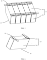
FIG. 4 is a schematic structural diagram of a step in a grouping process of battery cells in a battery according to an embodiment of this disclosure. -
FIG. 5 is a schematic structural diagram of a step in a grouping process of battery cells in a battery according to an embodiment of this disclosure. -
FIG. 6 is a schematic structural diagram of a battery cell in a battery according to an embodiment of this disclosure. -
FIG. 7 is a schematic structural diagram of a connection between a pole assembly and an electrode assembly in a battery cell in a battery according to an embodiment of this disclosure. -
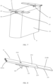
FIG. 8 is a schematic structural diagram of a pole assembly of a battery cell in a battery according to an embodiment of this disclosure. -
FIG. 9 is a schematic structural top view of the pole assembly inFIG. 8 . -
FIG. 10 is a schematic structural diagram of a direction A-A inFIG. 9 . - The following clearly and completely describes technical solutions in embodiments of this disclosure with reference to the accompanying drawings in the embodiments of this disclosure. Apparently, the described embodiments are some but not all embodiments of this disclosure. The following description of at least one exemplary embodiment is merely illustrative and definitely is not construed as any limitation on this disclosure or on application or use of this disclosure. All other embodiments obtained by persons of ordinary skill in the art based on the embodiments of this disclosure without creative efforts shall fall within the protection scope of this disclosure.
- Unless otherwise specified, relative arrangements of components and steps, numerical expressions, and numerical values set forth in these embodiments do not constitute a limitation on the scope of this disclosure. In addition, it should be understood that, for ease of description, sizes of various parts shown in the accompanying drawings are not drawn to scale. The technologies, methods, and devices known to those of ordinary skill in the related art may not be discussed in detail, but in appropriate circumstances, the technologies, methods, and devices should be regarded as being authorized as a part of the specification. In all examples shown and discussed herein, any specified value should be interpreted as merely illustrative rather than restrictive. Therefore, other examples of the exemplary embodiments may have different values. It should be noted that similar reference numerals and letters indicate similar items in the following drawings, and therefore once an item is defined in one drawing, it does not need to be further discussed in the subsequent drawings.
- In the description of this disclosure, it should be understood that the use of terms such as "first", "second", and the like to define parts is merely for the purpose of distinguishing between the corresponding parts. Unless otherwise stated, these terms do not have special meanings, and therefore shall not be construed as limitations on the protection scope of this disclosure.
- In the description of this disclosure, it should be understood that orientations or positional relationships indicated by orientation terms such as "front, rear, upper, lower, left, and right", "transverse, vertical, perpendicular, and horizontal", and "top and bottom" are usually based on the orientations or positional relationships as shown in the accompanying drawings. In the absence of any indication to the contrary, these terms are merely for the ease and brevity of description of this disclosure rather than indicating or implying that the means or components mentioned must have specific orientations or must be constructed or manipulated according to specific orientations, and therefore shall not be construed as any limitations on embodiments of this application. The orientation terms "inside and outside" refer to the inside and outside with respect to the contours of the components themselves.
- In the process of implementing this disclosure, the inventors have found that in the related art, when battery cells are arranged into groups, electrical connections between different battery cells are generally implemented by welding electrical connection pieces to poles. Difficulties in welding between electrical connection pieces to electrode terminals are high, and when battery cells are connected by welding, the battery cells are not easy to disassemble, leading to high difficulties in maintenance. Additionally, welding slag produced during welding may cause damage to surfaces of battery cells or related components, or even cause a risk of short circuit.
- To solve the foregoing technical problems in batteries and battery cells, embodiments of this disclosure provide an electrode terminal that can implement electrical connections between battery cells without the need for welding. Further, the embodiments of this disclosure also provide a pole assembly that includes such electrode terminal, a battery that includes such electrode terminal or pole assembly, and an electric device that includes such battery.
- The embodiments of this disclosure provide an electric device that uses a battery as a power source, where the battery is configured to supply electrical energy to the electric device. The electric device may be but is not limited to a mobile phone, a portable device, a notebook computer, an electric bicycle, an electric vehicle, a ship, a spacecraft, an electric toy, an electric tool, or the like. For example, the spacecraft includes an airplane, a rocket, a space shuttle, a spaceship, and the like; the electric toy includes a fixed or mobile electric toy, for example, a game console, an electric toy car, an electric toy ship, an electric toy airplane, and the like; the electric tool includes an electric metal cutting tool, an electric grinding tool, an electric assembly tool, and an electric railway-specific tool, for example, an electric drill, an electric grinder, an electric wrench, an electric screwdriver, an electric hammer, an electric impact drill, a concrete vibrator, and an electric planer.
- The battery mentioned in the embodiments of this disclosure is a single physical module that includes one or more battery cells for providing a higher voltage and capacity. The battery may include three forms: battery cell, battery module, and battery pack.
- A battery cell is a smallest element constituting a battery module or battery pack. A plurality of battery cells can be connected in series and/or in parallel through electrode terminals for various application scenarios, in some high-power application scenarios such as an electric vehicle.
- A battery module is formed by electrically connecting a specific quantity of battery cells and putting the battery cells into a frame to protect the battery cells from external impact, heat, vibration, and the like. With the development of technologies, the battery module may be omitted, that is, the battery pack is directly formed using battery cells.
- A battery pack is a final state of a battery system assembled in a high-power electric device such as an electric vehicle. The battery pack typically includes a box configured to enclose one or more battery cells. The box can prevent liquids or other foreign matter from affecting charging or discharging of the battery cell. The box is generally formed by a box shell and a box cover. Most existing battery packs are formed by assembling various control and protection systems such as a battery management system (Battery Management System, BMS) and a thermal management part on one or more battery modules. With such improvement, weight energy density and volumetric energy density of the battery system are increased, and the number of parts is remarkably reduced.
- For ease of description, an electric device being a vehicle D according to an embodiment of this disclosure is used as an example for the following description.
- Refer to
FIGs. 1 and 2. FIG. 1 is a schematic structural diagram of a vehicle D according to some embodiments of this disclosure. The vehicle D may be a fossil fuel vehicle, a natural-gas vehicle, or a new energy vehicle, where the new energy vehicle may be a battery electric vehicle, a hybrid electric vehicle, a range-extended vehicle, or the like. The vehicle D is provided with a battery B inside, where the battery B may be disposed at the bottom, front or rear of the vehicle D. The battery B may be configured to supply power to the vehicle D, for example, may be used as an operational power source for the vehicle D. -
FIG. 2 shows a bottom structure of the vehicle shown inFIG. 1 . The battery B may be disposed on the chassis CH of the vehicle D. The vehicle D may further include a controller CON and a motor M. The battery B is configured to provide electrical energy for operation of the motor M and other components in the vehicle D, and the controller CON is configured to control the motor M to operate, for example, to satisfy power needs of start, navigation, and running of the vehicle D. - In some embodiments of this disclosure, the battery B can be used as not only the operational power source for the vehicle D but also a driving power source for the vehicle D, replacing or partially replacing fossil fuel or natural gas to provide driving traction for the vehicle D.
- Referring to
FIG. 3, FIG. 3 is an exploded view of a battery B according to some embodiments of this disclosure. - The battery B includes a
box 1 and abattery cell 20 accommodated in thebox 1. Thebox 1 includes abox shell 11 and abox cover 12 snap-fitted with thebox shell 11, and thebox 1 is configured to provide an accommodating space for thebattery cell 20. In the above embodiments, thebox 1 is a cuboid as a whole. In an embodiment not shown in the figure, thebox 1 may alternatively be other shapes, for example, a cylinder. - In the battery B, the
battery cell 20 is provided in plurality, and the plurality ofbattery cells 20 may be connected in series, parallel, or series-parallel, where being connected in series-parallel means a combination of series and parallel connections of the plurality ofbattery cells 20. The plurality ofbattery cells 20 may be directly connected in series, parallel, or series-parallel, and then an entirety of the plurality ofbattery cells 20 is accommodated in thebox 1. - As shown in
FIG. 3 , the battery B may include a plurality ofbattery cells 20 that are first connected in series, parallel, or series-parallel to formbattery groups 2. Thebattery groups 2 may form a battery module. A plurality ofbattery groups 2 are then connected in series, parallel, or series-parallel to form an entirety which is accommodated in thebox 1. The battery B may further include other structures. For example, the battery B may further include a busbar configured to implement electrical connection between the plurality ofbattery cells 20. - The battery cell may include a lithium-ion battery, a lithium-sulfur battery, a sodium-lithium-ion battery, a sodium-ion battery, a magnesium-ion battery, or the like, or may be a primary battery, a secondary battery, or the like. This is not limited in the embodiments of this disclosure. The battery cell may be cylindrical, flat, cuboid, or of other shapes. This is not limited in the embodiments of this disclosure either. Battery cells are typically divided into three types by packaging method: cylindrical cell, prismatic cell, and pouch cell. This is not limited in the embodiments of this disclosure either.
- The battery cell mainly includes an electrode assembly, a housing, and an end cover assembly, with the electrode assembly enclosed in the housing through an end cover of the end cover assembly.
- For the
battery cell 20 provided in some embodiments of this disclosure, thebattery cell 20 includes acell housing 21, apole assembly 22, and anelectrode assembly 23. - The cell housing may be of various shapes and sizes, such as a rectangular shape, a cylindrical shape, and a hexagonal prism shape. Specifically, the shape of the cell housing may be determined based on a specific shape and size of the electrode assembly. The cell housing may be made of materials such as copper, iron, aluminum, stainless steel, aluminum alloy, and plastic.
- The
electrode assembly 23 is disposed inside thecell housing 21. Theelectrode assembly 23 is a component in which electrochemical reactions occur in thebattery cell 20. - The
cell housing 21 is a component that provides an accommodating space for accommodating theelectrode assembly 23, an electrolyte, and other components. Thecell housing 21 includes ahousing body 211 with an opening and anend cover 212 for sealing the opening. Thehousing body 211 and theend cover 212 may be separate components, thehousing body 211 is provided with the opening, and theend cover 212 covers the opening to form the internal environment of thebattery cell 20. Theend cover 212 and thehousing body 211 are not limited and may also be integrated. Specifically, theend cover 212 and thehousing body 211 may form a shared connection surface before other components are disposed in the housing, and then, thehousing body 211 is covered with theend cover 212 and thehousing body 211 and theend cover 212 are sealed into an entirety when inside of thehousing body 211 needs to be enclosed. - In some embodiments of this disclosure, the electrode terminal includes a connection hole for electrical connection with a sampling component. The sampling component belongs to a sampling assembly of the battery. The sampling assembly is coupled to a battery management system to obtain operational data of the battery, and generally includes a circuit board and a sampling component that is signally connected to the circuit board. The sampling component is configured to obtain the operational data of the battery, for example, temperature and pressure. The circuit board is signally connected to the sampling component to receive the operational data collected by the sampling component and is signally connected to the battery management system to upload the operational data of the battery to the battery management system. The electrode terminal in the embodiments of this disclosure is electrically connected to the sampling component through the connection hole on the electrode terminal, so that the operational parameters of the battery cell in which the electrode terminal is located can be sampled and transmitted to the battery management system through the circuit board. The sampling component may be, for example, a temperature sensor or a pressure sensor, and the circuit board may be, for example, a flexible printed circuit (flexible printed circuit, FPC). Specific forms of the sampling component and circuit board are not limited in this disclosure.
- As shown in
FIGs. 4 to 10 , an embodiment of this disclosure provides anelectrode terminal 221 configured to input current to and output current from abattery cell 20. Theelectrode terminal 221 includes apole body 2211, and thepole body 2211 includes a firstelectrical connection portion 2211A and a secondelectrical connection portion 2211B. The secondelectrical connection portion 2211B is electrically connected to the firstelectrical connection portion 2211A, and the secondelectrical connection portion 2211B is adapted to the firstelectrical connection portion 2211A in shape, such that electrical connection between theelectrode terminals 221 of twobattery cells 20 is implemented through fitting in shape between the firstelectrical connection portion 2211A of onebattery cell 20 and the secondelectrical connection portion 2211B of theother battery cell 20. - For the
electrode terminal 221, the firstelectrical connection portion 2211A is adapted to the secondelectrical connection portion 2211B in shape, such that electrical connection between theelectrode terminals 221 of twobattery cells 20 is implemented through fitting in shape between the firstelectrical connection portion 2211A of theelectrode terminal 221 of onebattery cell 20 and the secondelectrical connection portion 2211B of theelectrode terminal 221 of theother battery cell 20. In this way, whendifferent battery cells 20 usingsuch electrode terminal 221 are arranged into groups, it is not necessary to implement electrical connection by welding. Instead, it is only necessary to make the firstelectrical connection portion 2211A of one of twoelectrode poles 221 of twobattery cells 20 in a group fit with the secondelectrical connection portion 2211B of the other one in shape, making the grouping of correspondingbattery cells 20 convenient and quick, reducing the difficulties in disassembly, and avoiding damage to surfaces ofbattery cells 20 or related components or short circuit caused by welding slag produced. In addition, theelectrode terminal 22 of this disclosure integrates the functions of a pole and an electrical connection piece in the related art, simplifying a structure and assembly process of a battery that includessuch electrode terminal 22. - As shown in
FIGs. 4 to 9 , for theelectrode terminal 221 in some embodiments, the firstelectrical connection portion 2211A includes a slot, and the secondelectrical connection portion 2211B includes a plug adapted to the slot in shape. - The first
electrical connection portion 2211A and the secondelectrical connection portion 2211B are respectively provided as including a slot and a plug. In this way, when twobattery cells 20 are arranged into a group, it is only necessary to make the slot of the firstelectrical connection portion 2211A of one of twoelectrode terminals 221 to be electrically connected to each other fit with the plug of the secondelectrical connection portion 2211B of the other one to complete the required electrical connection. This allows for easy grouping, disassembly, and maintenance ofbattery cells 20. - As shown in
FIGs. 4 to 9 , for theelectrode terminal 221 in some embodiments, the slot is a single flat mouth, and the plug is a plug-in piece adapted to the single flat mouth in shape. - The provision of the slot as a single flat mouth and the plug as a plug-in piece allows for easy processing and operation and high connection stability.
- In embodiments not shown in the figures, the connection form of the first electrical connection portion and the second electrical connection portion is not limited thereto. For example, the first electrical connection portion and the second electrical connection portion can be arranged as plug and slot in other forms, such as multiple pins fitting with multiple pin sockets. For another example, the first electrical connection portion and the second electrical connection portion can simultaneously implement structural connection and electrical connection through snap connection.
- As shown in
FIGs. 4 to 10 , for theelectrode terminal 221 in some embodiments, thepole body 2211 of theelectrode terminal 221 is sheet-shaped. - The
pole body 2211 is provided as sheet-shaped, and reasonable arrangement of relative positions of thepole body 2211 and acell housing 211 of thebattery cell 20 allows for smaller distance from a side of theelectrode terminal 221 away from thecell housing 21 to thecell housing 21, thus leading to relatively reduced overall sizes of thebattery cell 20 and the battery that uses thebattery cell 20. - The form of the pole body is not limited to sheet-shaped, for example, it may alternatively be cylindrical, semi-cylindrical, or another form.
- As shown in
FIGs. 4 to 10 , for theelectrode terminal 221 in some embodiments, the firstelectrical connection portion 2211A and the secondelectrical connection portion 2211B are respectively disposed at two opposite ends of thepole body 2211. - The first
electrical connection portion 2211A and the secondelectrical connection portion 2211B being disposed at two opposite ends of thepole body 2211 makes it easy to achieve docking of the firstelectrical connection portion 2211A and the secondelectrical connection portion 2211B whendifferent battery cells 20 are arranged into groups, making the grouping convenient and quick. - The positions of the first
electrical connection portion 2211A and the secondelectrical connection portion 2211B are not limited to being arranged as opposite each other, as long as they are suitable for electrical connection between theelectrode terminals 221 of twobattery cells 20 to be implemented through fitting in shape between the firstelectrical connection portion 2211A of onebattery cell 20 and the secondelectrical connection portion 2211B of theother battery cell 20. - For the
electrode terminal 221 in some embodiments, theelectrode terminal 221 further includes aconnection hole 2212 provided in thepole body 2211, where theconnection hole 2212 is configured to allow for electrical connection between thepole body 2211 and a sampling component that performs sampling for operational parameters of thebattery cell 20 in which theelectrode terminal 221 is located. - The provision of the
connection hole 2212 on the electrode terminal for electrical connection with the sampling component makes it easy for the sampling component to be electrically connected to theelectrode terminal 221 to perform sampling on thebattery cell 20. The sampling component and theelectrode terminal 221 can be electrically connected through riveting, threaded connections, or the like, which can avoid welding connection, conducive to reducing the damage to the surfaces of related components or the risk of short circuit caused by welding slag. - For the
electrode terminal 221 in some embodiments, theelectrode terminal 221 further includes afirst insulation portion 2213, where thefirst insulation portion 2213 is disposed on a surface of thepole body 2211. - The provision of the
first insulation portion 2213 on the surface of thepole body 2211 of theelectrode terminal 221 facilitates electrical insulation between thepole body 2211 and adjacent electrical elements, which helps reduce the risk of short circuit. Thefirst insulation portion 2213 is, for example, an insulation coating or insulation sleeve provided on an outer side of theelectrode terminal 221. - For the
electrode terminal 221 in some embodiments, the firstelectrical connection portion 2211A is configured to be electrically connected to anadapter 222 of thebattery cell 20, and thefirst insulation portion 2213 covers at least an outer side of the firstelectrical connection portion 2211A of theelectrode terminal 221. - The above configuration facilitates electrical insulation between a portion, of the
pole body 2211, connected to theadapter 222 and adjacent electrical elements, which helps reduce the risk of short circuit. - For the
electrode terminal 221 in some embodiments, the firstelectrical connection portion 2211A is integrally formed with or directly connected to the secondelectrical connection portion 2211B. - The first
electrical connection portion 2211A being integrally formed with or directly connected to the secondelectrical connection portion 2211B allows for simple and stable electrical structure and convenient and quick processing of theelectrode terminal 221. - As shown in
FIGs. 4 to 10 , an embodiment of this disclosure further provides apole assembly 22 including theelectrode terminal 221 according to the first aspect of this disclosure and anadapter 222. The adapter is electrically connected to the pole body 2221 of theelectrode terminal 221, and theadapter 222 is configured to be electrically connected to anelectrode assembly 23 of abattery cell 20 in which theadapter 222 is located. - The
pole assembly 22 of this disclosure has the advantages of theelectrode terminal 221 of this disclosure. - For the
pole assembly 22 in some embodiments of this disclosure, thepole body 2211 of theelectrode terminal 221 is sheet-shaped, and theadapter 222 is connected to a side of thepole body 2211. - The
pole body 2211 is provided as sheet-shaped, and theadapter 222 is connected to a side of thepole body 2211, which can allow for smaller distance from a side of theelectrode terminal 221, in thebattery cell 20 that uses thepole assembly 22, away from thecell housing 21 to thecell housing 21, thus leading to relatively reduced overall sizes of thebattery cell 20 and the battery that uses thebattery cell 20. - For the
pole assembly 22 in some embodiments of this disclosure, theadapter 222 includes an adapting piece perpendicularly connected to thepole body 2211. - The adapting piece that is perpendicularly connected to the
pole body 2211 being provided in theadapter 222 facilitates reasonable arrangement of theelectrode assembly 23,cell housing 21,adapter 222, andelectrode terminal 221 of the battery cell. This is not only conducive to reducing the volume of thebattery cell 20 that uses thepole assembly 22, but also conducive to reducing space occupation during grouping ofbattery cells 20, so as to help reduce the volume of the battery that uses thebattery cell 20. - For the
pole assembly 22 in some embodiments of this disclosure, the firstelectrical connection portion 2211A and the secondelectrical connection portion 2211B are respectively disposed at two opposite ends of thepole body 2211, and two side surfaces of the adapting piece respectively face toward the firstelectrical connection portion 2211A and the secondelectrical connection portion 2211B. - The two side surfaces of the adapting piece respectively facing toward the first
electrical connection portion 2211A and the secondelectrical connection portion 2211B facilitates reasonable arrangement of theelectrode assembly 23,cell housing 21,adapter 222, andelectrode terminal 221 of the battery cell. This is not only conducive to reducing the volume of thebattery cell 20 that uses thepole assembly 22, but also conducive to reducing space occupation during grouping ofbattery cells 20, so as to help reduce the volume of the battery that uses thebattery cell 20. - For the
pole assembly 22 in some embodiments of this disclosure, theadapter 222 is integrally formed with or directly connected to theelectrode terminal 221. - The
adapter 222 being integrally formed with or directly connected to theelectrode terminal 221 allows for simple and stable electrical structure and convenient and quick processing of thepole assembly 22. - For the
pole assembly 22 in some embodiments of this disclosure, thepole assembly 22 further includes asecond insulation portion 223, where thesecond insulation portion 223 is disposed on a side of theelectrode terminal 221 close to theadapter 222. - The
second insulation portion 223 being disposed on the side of theelectrode terminal 221 close to theadapter 222 is conducive to insulating thepole body 2211 and theadapter 222 from thecell housing 21 of thebattery cell 20 after thepole assembly 22 is assembled into thecell housing 21 of thebattery cell 20. Thesecond insulation portion 223 is, for example, an insulation pad. When thepole assembly 22 is assembled with the end cover of thebattery cell 20, thesecond insulation portion 223 is located between theelectrode terminal 221 and thecell housing 222, so that theelectrode terminal 221 and theadapter 222 are electrically insulated from thecell housing 222. - An embodiment of this disclosure further provides a battery including a
battery cell 20. Thebattery cell 20 includes anelectrode assembly 23 and theelectrode terminal 221 according to the first aspect of this disclosure or thepole assembly 22 according to the second aspect of this disclosure, where theelectrode terminal 221 is electrically connected to theelectrode assembly 23 of thebattery cell 20. - The battery according to some embodiments of this disclosure has the same advantages as the
electrode terminal 221 according to the embodiments of this disclosure and thepole assembly 22 according to the embodiments of this disclosure. - For the battery in some embodiments, the
battery cell 20 includes twoelectrode poles 221, where the twoelectrode poles 221 are electrically connected to ananode tab 232 andcathode tab 233 of theelectrode assembly 23 respectively. - The two
electrode poles 221 of thebattery cell 20 being electrically connected to theanode tab 232 andcathode tab 233 of theelectrode assembly 23 respectively allows allelectrode poles 221 to implement quick and convenient electrical connections through fitting in shape during grouping ofbattery cells 20, without the need for welding. - For the battery in some embodiments, two
electrode poles 221 of thebattery cell 20 are arranged side by side, and an arrangement direction of the firstelectrical connection portion 2211A and secondelectrical connection portion 2211B of oneelectrode terminal 221 is the same as an arrangement direction of the firstelectrical connection portion 2211A and secondelectrical connection portion 2211B of theother electrode terminal 221; or twoelectrode poles 221 of thebattery cell 20 are arranged side by side, and an arrangement direction of the firstelectrical connection portion 2211A and secondelectrical connection portion 2211B of oneelectrode terminal 221 is opposite to an arrangement direction of the firstelectrical connection portion 2211A and secondelectrical connection portion 2211B of theother electrode terminal 221. - The above arrangement of the
electrode terminals 221 of thebattery cell 20 allows for flexible arrangement of directions of theelectrode terminals 221 based on grouping needs ofbattery cells 20, facilitating quick grouping ofbattery cells 20. - For the battery in some embodiments, the battery includes at least two
battery cells 20, where electrical connection between theelectrode terminals 221 of each adjacent pair ofbattery cells 20 is implemented through fitting in shape between the firstelectrical connection portion 2211A of onebattery cell 20 and the secondelectrical connection portion 2211B of theother battery cell 20. - The electrical connection between the
electrode terminals 221 of each adjacent pair ofbattery cells 20 being implemented through fitting in shape between the firstelectrical connection portion 2211A of theelectrode terminal 221 of onebattery cell 20 and the secondelectrical connection portion 2211B of theelectrode terminal 221 of theother battery cell 20 allows for electrical connections implemented without welding, making the grouping ofbattery cells 20 convenient and quick, reducing the difficulties in disassembly, and avoiding damage to surfaces of battery cells or related components or short circuit caused by welding slag produced. - For the battery in some embodiments, the
battery cell 20 includes thepole assembly 22, and theadapter 222 of thepole assembly 22 is directly connected to theelectrode assembly 23 of thebattery cell 20 in which thepole assembly 22 is located. - The
adapter 222 being directly connected to theelectrode assembly 23 of thebattery cell 20 allows for simple and stable electrical structure and convenient and quick processing of thebattery cell 20. - An embodiment of this disclosure further provides an electric device including the battery according to the embodiments of this disclosure. The battery is configured to supply power to the electric device.
- The electric device according to some embodiments of this disclosure has the same advantages as the battery according to some embodiments of this disclosure.
- The following describes the
electrode terminal 221,pole assembly 22, and battery B in some embodiments this disclosure with reference toFIGs. 4 to 10 . - As shown in
FIG. 3 , the battery B includes abox 1 and a plurality ofbattery groups 2 located inside thebox 1. Thebox 1 includes abox shell 11 and abox cover 12. Eachbattery group 2 includesmultiple battery cells 20 arranged into the group. Thebattery cells 20 arranged into the group are connected in parallel to form thebattery group 2. - As shown in
FIGs. 4 to 7 , thebattery cell 20 includes acell housing 21, apole assembly 22, and anelectrode assembly 23. Thecell housing 21 includes ahousing body 211 with an opening and anend cover 212 for sealing the opening. Theelectrode assembly 23 is sealed inside thecell housing 21. Theelectrode assembly 23 includes abody portion 231 and ananode tab 232 andcathode tab 233 extending from a same side of thebody portion 231. One of twopole assemblies 22 is electrically connected to theanode tab 232 of theelectrode assembly 23 to serve as an anode pole, and the other is electrically connected to thecathode tab 233 of theelectrode assembly 23 to serve as a cathode pole. During assembly of the battery cell, the twopole assemblies 22 are mounted on theend cover 212. Theelectrode terminal 221 and thesecond insulation portion 223 are located outside thecell housing 21, theadapter 222 runs through theend cover 212 from the opening in theend cover 212 and is electrically connected to theelectrode assembly 23, and then theelectrode assembly 23 is put into thehousing body 211 and thehousing body 211 is sealed with theend cover 212. - Markings can be separately set on the anode pole and the cathode pole to distinguish between the anode pole and the cathode pole during grouping of the battery cells to prevent connection error.
- As shown in
FIGs. 4 to 6 , in this embodiment, twoelectrode poles 221 of thebattery cell 20 are arranged side by side, and an arrangement direction of the firstelectrical connection portion 2211A and secondelectrical connection portion 2211B of oneelectrode terminal 221 is opposite to an arrangement direction of the firstelectrical connection portion 221 1A and secondelectrical connection portion 2211B of theother electrode terminal 221. - As shown in
FIGs. 4 to 10 , in this embodiment, theelectrode terminal 221 includes apole body 2211, aconnection hole 2212, and afirst insulation portion 2213. - The
pole body 2211 includes a firstelectrical connection portion 2211A and a secondelectrical connection portion 2211B that are integrally disposed. Thepole body 2211 is made of metal, for example, aluminum or copper. - The
pole body 2211 of theelectrode terminal 221 is sheet-shaped. The firstelectrical connection portion 2211A and the secondelectrical connection portion 2211B are respectively disposed at two opposite ends of thepole body 2211. - The first
electrical connection portion 2211A includes a single flat mouth as a slot, and the secondelectrical connection portion 2211B includes a plug-in piece as a plug. The plug-in piece is adapted to the single flat mouth in shape. - As shown in
FIGs. 4 to 6 , when a plurality ofbattery cells 20 in the battery B are arranged into groups, forelectrode terminals 221, to be connected in correspondence, of each adjacent pair ofbattery cells 20 in the plurality ofbattery cells 20, electrical connection between thecorresponding electrode terminals 221 of the twobattery cells 20 can be implemented by inserting the plug-in piece of the secondelectrical connection portion 2211B of oneelectrode terminal 221 into the single flat mouth of the firstelectrical connection portion 2211A of theother electrode terminal 221. - The
connection hole 2212 is configured to allow for electrical connection between thepole body 2211 and a sampling component that performs sampling for operational parameters of thebattery cell 20 in which theelectrode terminal 221 is located. The sampling component can be electrically connected to theelectrode terminal 221 through riveting or threaded connection at theconnection hole 2212. - The
first insulation portion 2213 is disposed on a surface of thepole body 2211. Specifically, thefirst insulation portion 2213 is an insulation coating provided on an outer side of the firstelectrical connection portion 2211A of theelectrode terminal 221. - As shown in
FIGs. 4 and5 , after at least twoelectrode terminals 221 are connected in sequence, since the plug-in pieces are inserted into the single flat mouths, only two of the above firstelectrical connection portions 2211A are located on the outer sides, and thefirst insulation portions 2213 of allconnected electrode terminals 221 can cover all thepole bodies 2211 except for the plug-in piece of the last electrode terminal, thus implementing the insulation of thepole bodies 2211 after the plurality ofelectrode terminals 221 are connected. - As shown in
FIGs. 4 to 10 , in this embodiment, thepole assembly 22 includes anelectrode terminal 221, anadapter 222, and asecond insulation portion 223. - The
adapter 222 is welded to a tab of theelectrode assembly 23 of thebattery cell 20 in which theadapter 222 is located. As shown inFIG. 8 , theadapter 222 is sheet-shaped and is perpendicularly welded to a side of thepole body 2211. Two side surfaces of theadapter 222 respectively face toward the firstelectrical connection portion 2211A and the secondelectrical connection portion 2211B. In this embodiment, after all parts of thebattery cell 20 are assembled, theelectrode terminal 221 extends along a direction perpendicular to a large surface of thebattery cell 20, with the firstelectrical connection portion 2211A of theelectrode terminal 221 located on thetop cover 212, and the secondelectrical connection portion 2211B of theelectrode terminal 221 extending toward an outer side of thetop cover 212. When twobattery cells 20 are arranged into a group, the secondelectrical connection portion 2211B can be inserted right into the firstelectrical connection portion 2211A of theother battery cell 20 until the large surfaces of the twobattery cells 20 are attached to each other. - In the embodiment shown in
FIGs. 4 to 10 , thecell housing 21 of thebattery cell 20 is rectangular, and the large surface of thebattery cell 20 refers to the largest side surface of thebattery cell 20. - In the embodiment shown in
FIGs. 4 to 10 , theelectrode terminal 221 andpole body 2211 of thepole assembly 22 are sheet-shaped, and the side surface of thepole body 2211 connected to theadapter 222 is opposite thetop cover 212. After a plurality ofbattery cells 20 are electrically connected through theirrespective electrode terminals 221, theconnected electrode terminals 221 form a strip. - The
second insulation portion 223 is disposed on a side of theelectrode terminal 221 close to theadapter 222. Thesecond insulation portion 223 is an insulation pad. When thepole assembly 22 is assembled with theend cover 212 of thebattery cell 20, thesecond insulation portion 223 is located between theelectrode terminal 221 and thecell housing 21, so that theelectrode terminal 221 and theadapter 222 are electrically insulated from theend cover 212. - As can be seen from the above description, the
electrode terminal 221,pole assembly 22, battery B, and electric device D in the embodiments of this disclosure have at least one of the following advantages: - The
pole assembly 22 and itselectrode terminal 221 in the embodiments of this disclosure being used in a battery cell can implement direct assembly when at least twobattery cells 20 are arranged into groups, without the need for a welding process. - Since the
pole body 2211 is provided with theconnection hole 2212, non-welding connection between theelectrode terminal 221 and a sampling component can be implemented. Therefore, whenbattery cells 20 are arranged into groups the risk that welding slag produced during the welding process for high-and-low-voltage connection can be avoided. - Reasonable arrangement of the structures and positions of the
electrode terminal 221 and theadapter 222 is also conducive to simplifying the structures of thebattery cell 20 and the battery B that includessuch battery cell 20 and to reducing the space occupied. - Since the two opposite ends of the
electrode terminal 221 are respectively provided with the slot and the plug, the anode pole and the cathode pole can be arranged as opposite in directions, so as to implement direct plug-in connection during series connection. - Since insulation treatment is performed on the outer layer of the
pole body 2211, after a plurality of electrode terminals are connected, there is no high-voltage exposure except for an electrical connection portion (for example, a plug-in piece) that can serve as a lead terminal. - In conclusion, it should be noted that the above embodiments are merely intended for describing the technical solutions of this disclosure but not for limiting this disclosure. Although this application is described in detail with reference to preferred embodiments, persons of ordinary skill in the art should understand that they may still make modifications to specific embodiments of this disclosure or make equivalent replacements to some or all technical features. All such modifications or replacements shall be covered in the scope of the technical solutions claimed in this disclosure.
Claims (21)
- An electrode terminal (221), configured to input current to and output current from a battery cell (20) and comprising a pole body (2211), wherein the pole body (2211) comprises:a first electrical connection portion (2211A); anda second electrical connection portion (2211B) electrically connected to the first electrical connection portion (2211A) and adapted to the first electrical connection portion (2211A) in shape, such that electrical connection between the electrode terminals (221) of two battery cells (20) is implemented through fitting in shape between the first electrical connection portion (2211A) of one battery cell (20) and the second electrical connection portion (2211B) of the other battery cell (20).
- The electrode terminal (221) according to claim 1, wherein the first electrical connection portion (2211A) comprises a slot, and the second electrical connection portion (2211B) comprises a plug adapted to the slot in shape.
- The electrode terminal (221) according to claim 1 or 2, wherein the slot is a single flat mouth, and the plug is a plug-in piece adapted to the single flat mouth in shape.
- The electrode terminal (221) according to any one of claims 1 to 3, wherein the pole body (2211) is sheet-shaped.
- The electrode terminal (221) according to any one of claims 1 to 4, wherein the first electrical connection portion (2211A) and the second electrical connection portion (2211B) are respectively disposed at two opposite ends of the pole body (2211).
- The electrode terminal (221) according to any one of claims 1 to 5, further comprising a connection hole (2212) provided in the pole body (2211), wherein the connection hole (2212) is configured to allow for electrical connection between the pole body (2211) and a sampling component that performs sampling for operational parameters of the battery cell (20) in which the electrode terminal (221) is located.
- The electrode terminal (221) according to any one of claims 1 to 6, further comprising a first insulation portion (2213), wherein the first insulation portion (2213) is disposed on a surface of the pole body (2211).
- The electrode terminal (221) according to claim 7, wherein the first electrical connection portion (2211A) is configured to be electrically connected to an adapter (222) of the battery cell (20), and the first insulation portion (2213) covers at least an outer side of the first electrical connection portion (2211A) of the electrode terminal (221).
- The electrode terminal (221) according to any one of claims 1 to 8, wherein the first electrical connection portion (2211A) is integrally formed with or directly connected to the second electrical connection portion (2211B).
- A pole assembly (22), comprising:the electrode terminal (221) according to any one of claims 1 to 9; andan adapter (222) electrically connected to the pole body (2221) of the electrode terminal (221), wherein the adapter (222) is configured to be electrically connected to an electrode assembly (23) of a battery cell (20) in which the adapter (222) is located.
- The pole assembly (22) according to claim 10, wherein the pole body (2211) of the electrode terminal (221) is sheet-shaped, and the adapter (222) is connected to a side of the pole body (2211).
- The pole assembly (22) according to claim 11, wherein the adapter (222) comprises an adapting piece perpendicularly connected to the pole body (2211).
- The pole assembly (22) according to claim 12, wherein the first electrical connection portion (2211A) and the second electrical connection portion (2211B) are respectively disposed at two opposite ends of the pole body (2211), and two side surfaces of the adapting piece respectively face toward the first electrical connection portion (2211A) and the second electrical connection portion (2211B).
- The pole assembly (22) according to any one of claims 10 to 13, wherein the adapter (222) is integrally formed with or directly connected to the electrode terminal (221).
- The pole assembly (22) according to any one of claims 10 to 14, further comprising a second insulation portion (223), wherein the second insulation portion (223) is disposed on a side of the electrode terminal (221) close to the adapter (222).
- A battery, comprising a battery cell (20), wherein the battery cell (20) comprises:an electrode assembly (23); andthe electrode terminal (221) according to any one of claims 1 to 9 or the pole assembly (22) according to any one of claims 10 to 15, wherein the electrode terminal (221) is electrically connected to the electrode assembly (23) of the battery cell (20).
- The battery according to claim 16, wherein the battery cell (20) comprises two electrode poles (221), and the two electrode poles (221) are electrically connected to an anode tab (232) and cathode tab (233) of the electrode assembly (23) respectively.
- The battery according to claim 16 or 17, whereintwo electrode poles (221) of the battery cell (20) are arranged side by side, and an arrangement direction of the first electrical connection portion (2211A) and second electrical connection portion (2211B) of one electrode terminal (221) is the same as an arrangement direction of the first electrical connection portion (2211A) and second electrical connection portion (2211B) of the other electrode terminal (221); ortwo electrode poles (221) of the battery cell (20) are arranged side by side, and an arrangement direction of the first electrical connection portion (2211A) and second electrical connection portion (2211B) of one electrode terminal (221) is opposite to an arrangement direction of the first electrical connection portion (2211A) and second electrical connection portion (2211B) of the other electrode terminal (221).
- The battery according to any one of claims 16 to 18, comprising at least two battery cells (20), wherein electrical connection between the electrode terminals (221) of each adjacent pair of battery cells (20) is implemented through fitting in shape between the first electrical connection portion (2211A) of one battery cell (20) and the second electrical connection portion (2211B) of the other battery cell (20).
- The battery according to any one of claims 16 to 19, wherein the battery cell (20) comprises the pole assembly (22), and the adapter (222) of the pole assembly (22) is directly connected to the electrode assembly (23) of the battery cell (20) in which the pole assembly (22) is located.
- An electric device, comprising the battery according to any one of claims 16 to 20, wherein the battery is configured to supply power to the electric device.
Applications Claiming Priority (2)
| Application Number | Priority Date | Filing Date | Title |
|---|---|---|---|
| CN202210337176.0A CN116937081A (en) | 2022-03-31 | 2022-03-31 | Electrode terminals, pole assemblies, batteries and electrical equipment |
| PCT/CN2023/075983 WO2023185290A1 (en) | 2022-03-31 | 2023-02-14 | Electrode terminal, pole assembly, battery, and electric device |
Publications (2)
| Publication Number | Publication Date |
|---|---|
| EP4401233A1 true EP4401233A1 (en) | 2024-07-17 |
| EP4401233A4 EP4401233A4 (en) | 2025-04-09 |
Family
ID=88199125
Family Applications (1)
| Application Number | Title | Priority Date | Filing Date |
|---|---|---|---|
| EP23777669.5A Pending EP4401233A4 (en) | 2022-03-31 | 2023-02-14 | Electrode terminal, pole assembly, battery, and electric device |
Country Status (4)
| Country | Link |
|---|---|
| US (1) | US20240266694A1 (en) |
| EP (1) | EP4401233A4 (en) |
| CN (1) | CN116937081A (en) |
| WO (1) | WO2023185290A1 (en) |
Families Citing this family (1)
| Publication number | Priority date | Publication date | Assignee | Title |
|---|---|---|---|---|
| CN120879097B (en) * | 2025-09-26 | 2026-03-24 | 宁德时代新能源科技股份有限公司 | Battery device and electricity utilization device |
Family Cites Families (6)
| Publication number | Priority date | Publication date | Assignee | Title |
|---|---|---|---|---|
| US4106833A (en) * | 1977-09-02 | 1978-08-15 | The United States Of America As Represented By The Secretary Of The Navy | Quick disconnect intercell busbar for deep submergence batteries |
| US5662497A (en) * | 1995-11-03 | 1997-09-02 | New York State Electric & Gas Corporation | Modular battery terminal connector assembly |
| US8585422B2 (en) * | 2011-04-15 | 2013-11-19 | Rockwell Automation Technologies, Inc. | System for connecting motor drives |
| US20130260611A1 (en) * | 2012-04-03 | 2013-10-03 | Jang-Gun Ahn | Battery module |
| JP6741215B2 (en) * | 2017-01-20 | 2020-08-19 | 株式会社オートネットワーク技術研究所 | Connection module |
| CN214848960U (en) * | 2021-02-24 | 2021-11-23 | 厦门海辰新能源科技有限公司 | Battery module and secondary battery |
-
2022
- 2022-03-31 CN CN202210337176.0A patent/CN116937081A/en active Pending
-
2023
- 2023-02-14 EP EP23777669.5A patent/EP4401233A4/en active Pending
- 2023-02-14 WO PCT/CN2023/075983 patent/WO2023185290A1/en not_active Ceased
-
2024
- 2024-04-16 US US18/637,439 patent/US20240266694A1/en active Pending
Also Published As
| Publication number | Publication date |
|---|---|
| EP4401233A4 (en) | 2025-04-09 |
| US20240266694A1 (en) | 2024-08-08 |
| WO2023185290A1 (en) | 2023-10-05 |
| CN116937081A (en) | 2023-10-24 |
Similar Documents
| Publication | Publication Date | Title |
|---|---|---|
| CN216488286U (en) | Battery cell, battery and power consumption device | |
| CN219436019U (en) | Battery and electricity utilization device | |
| EP4106087A1 (en) | Battery cell, battery, power-consuming device, and manufacturing method and device for battery | |
| US20240283099A1 (en) | Battery cell, battery, power consumption device, and method and device for producing battery cell | |
| CN115172979B (en) | Battery modules, batteries and electrical devices | |
| CN218919088U (en) | End cover assembly of battery unit, battery and electricity utilization device | |
| US20250192375A1 (en) | Battery and electrical apparatus | |
| EP4258441A1 (en) | Battery, electric device, and battery preparation method and device | |
| CN115882132A (en) | Battery cell, battery, electric device, manufacturing method, and manufacturing apparatus | |
| US20240396128A1 (en) | Battery cell, battery, and electric device | |
| US20240266694A1 (en) | Electrode terminal, pole assembly, battery, and electric device | |
| CN115832443A (en) | Electrical equipment, battery, battery cell and manufacturing method thereof | |
| CN116508196A (en) | Battery cell, manufacturing method and system thereof, battery, and electrical device | |
| CN223743723U (en) | Sampling device, battery and electric equipment | |
| EP4475252A1 (en) | Battery cell, battery, electrical device, and manufacturing method | |
| US20260018690A1 (en) | High-voltage box, battery, and electrical device | |
| EP4492562A1 (en) | Battery cell, battery, and electric apparatus | |
| EP4510327A1 (en) | Battery cell, battery and electric device | |
| EP4492534A1 (en) | Battery cell, battery and electric apparatus | |
| CN217158566U (en) | Battery and electric equipment | |
| CN116706409A (en) | Battery, its manufacturing method and manufacturing system, and electrical device | |
| EP4354598A1 (en) | Battery cell and manufacturing method and manufacturing system therefor, and battery and electric apparatus | |
| CN116526074A (en) | Battery and electricity utilization device | |
| CN218867329U (en) | Battery and power consumption device | |
| CN219436092U (en) | Electrode assembly, battery cell, battery and electrical device |
Legal Events
| Date | Code | Title | Description |
|---|---|---|---|
| STAA | Information on the status of an ep patent application or granted ep patent |
Free format text: STATUS: THE INTERNATIONAL PUBLICATION HAS BEEN MADE |
|
| PUAI | Public reference made under article 153(3) epc to a published international application that has entered the european phase |
Free format text: ORIGINAL CODE: 0009012 |
|
| STAA | Information on the status of an ep patent application or granted ep patent |
Free format text: STATUS: REQUEST FOR EXAMINATION WAS MADE |
|
| 17P | Request for examination filed |
Effective date: 20240410 |
|
| AK | Designated contracting states |
Kind code of ref document: A1 Designated state(s): AL AT BE BG CH CY CZ DE DK EE ES FI FR GB GR HR HU IE IS IT LI LT LU LV MC ME MK MT NL NO PL PT RO RS SE SI SK SM TR |
|
| RAP1 | Party data changed (applicant data changed or rights of an application transferred) |
Owner name: CONTEMPORARY AMPEREX TECHNOLOGY(HONG KONG) LIMITED |
|
| REG | Reference to a national code |
Ref country code: DE Ref legal event code: R079 Free format text: PREVIOUS MAIN CLASS: H01M0050553000 Ipc: H01M0050503000 |
|
| A4 | Supplementary search report drawn up and despatched |
Effective date: 20250311 |
|
| RIC1 | Information provided on ipc code assigned before grant |
Ipc: H01R 11/28 20060101ALI20250305BHEP Ipc: H01M 50/258 20210101ALI20250305BHEP Ipc: H01M 50/249 20210101ALI20250305BHEP Ipc: H01M 50/569 20210101ALI20250305BHEP Ipc: H01M 50/55 20210101ALI20250305BHEP Ipc: H01M 50/514 20210101ALI20250305BHEP Ipc: H01M 50/50 20210101ALI20250305BHEP Ipc: H01M 50/553 20210101ALI20250305BHEP Ipc: H01M 50/503 20210101AFI20250305BHEP |
|
| DAV | Request for validation of the european patent (deleted) | ||
| DAX | Request for extension of the european patent (deleted) |