EP4401014A1 - Verfahren zur konstruktion eines trainierten modells - Google Patents
Verfahren zur konstruktion eines trainierten modells Download PDFInfo
- Publication number
- EP4401014A1 EP4401014A1 EP22864761.6A EP22864761A EP4401014A1 EP 4401014 A1 EP4401014 A1 EP 4401014A1 EP 22864761 A EP22864761 A EP 22864761A EP 4401014 A1 EP4401014 A1 EP 4401014A1
- Authority
- EP
- European Patent Office
- Prior art keywords
- data
- trained model
- robot
- motion
- training
- Prior art date
- Legal status (The legal status is an assumption and is not a legal conclusion. Google has not performed a legal analysis and makes no representation as to the accuracy of the status listed.)
- Pending
Links
Images


Classifications
-
- B—PERFORMING OPERATIONS; TRANSPORTING
- B25—HAND TOOLS; PORTABLE POWER-DRIVEN TOOLS; MANIPULATORS
- B25J—MANIPULATORS; CHAMBERS PROVIDED WITH MANIPULATION DEVICES
- B25J9/00—Programme-controlled manipulators
- B25J9/16—Programme controls
- B25J9/1628—Programme controls characterised by the control loop
- B25J9/163—Programme controls characterised by the control loop learning, adaptive, model based, rule based expert control
-
- G—PHYSICS
- G06—COMPUTING OR CALCULATING; COUNTING
- G06N—COMPUTING ARRANGEMENTS BASED ON SPECIFIC COMPUTATIONAL MODELS
- G06N20/00—Machine learning
-
- G—PHYSICS
- G05—CONTROLLING; REGULATING
- G05B—CONTROL OR REGULATING SYSTEMS IN GENERAL; FUNCTIONAL ELEMENTS OF SUCH SYSTEMS; MONITORING OR TESTING ARRANGEMENTS FOR SUCH SYSTEMS OR ELEMENTS
- G05B2219/00—Program-control systems
- G05B2219/30—Nc systems
- G05B2219/40—Robotics, robotics mapping to robotics vision
- G05B2219/40515—Integration of simulation and planning
Definitions
- the present disclosure relates to construction of a trained model by machine learning.
- PTL 1 discloses a system of this type.
- a motion prediction model is constructed by performing machine learning of data obtained when an operator manually and remotely controls a robot arm to perform a task. Based on output of the motion prediction model, the robot arm is automatically operated.
- the motion prediction model (a trained model) constructed as in PTL 1.
- various aspects such as the quality of the remote operation performed by a user during learning, the quality of the obtained training data, the quality of the constructed trained model, and the quality of the autonomous operation based on the output of the trained model, are compositely reflected in the quality of the autonomous motion of the robot arm.
- these qualities often have influences on each other. Therefore, it was difficult to evaluate each quality one by one. As a result, even if the need to improve the trained model arose, it was unclear what to improve and inefficient trial and error was required.
- the present disclosure is made in view of the situation described above, and its purpose is to obtain a high-performance trained model efficiently.
- An aspect of the present disclosure provides a construction method of a trained model as follows. That is, the construction method of the trained model includes a first process, a second process, a third process, a fourth process, a fifth process, and a sixth process.
- the first process data for performing machine learning of an operation of a controlled machine by a human is collected.
- the second process collected data that is the data collected is evaluated and, when it does not satisfy a predetermined evaluation criterion, the data is collected again.
- training data is selected from the collected data that satisfies the evaluation criterion.
- the training data is evaluated and, when it does not satisfy a predetermined evaluation criterion, the training data is selected again.
- a trained model is constructed by machine learning using the training data that satisfies the evaluation criterion.
- the trained model is evaluated and, when it does not satisfy a predetermined evaluation criterion, the trained model is trained again.
- the trained model can be constructed smoothly.
- a high-performance trained model can be efficiently obtained.
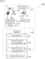
- FIG. 1 is a schematic diagram illustrating the robot operation system 100.
- FIG. 2 is a conceptual diagram illustrating operation information.
- FIG. 3 is a diagram showing an example of a series of tasks to be performed by a robot 11 and each of task states.
- the robot operation system 100 is a system that constructs a learning model 31 and operates a robot system 1 based on output of the learning model 31. As a result of the robot system 1 operating with the learning model 31, the robot 11 performs a task autonomously.
- the task performed by the robot 11 may be determined as desired. For example, it may be welding, assembly, machining, handling, painting, cleaning, or polishing.
- the robot system 1 includes a robot controlling apparatus 10, the robot (controlled machine) 11, and an operating apparatus 12.
- the apparatuses are connected to each other via a wired or wireless network and can exchange signals (data).
- the robot controlling apparatus 10 is comprised of a known computer.
- the robot controlling apparatus 10 includes a processing unit, such as a microcontroller, a CPU, a MPU, a PLC, a DSP, an ASIC or a FPGA, a robot memory unit, such as a ROM, a RAM or a HDD, and a communication unit that can communicate with an external apparatus.
- the robot memory unit stores, for example, a control application for controlling an arm or other parts.
- the robot controlling apparatus 10 can switch an operation mode of the robot 11 between a manual operation mode and an autonomous operation mode.
- a user operates the operating apparatus 12 as described below to make the robot 11 operate.
- the robot 11 autonomously operates based on the results of machine learning on the motion of the robot 11 operated manually.
- the robot 11 is configured, for example, as a vertical articulated robot with 6 degrees of freedom.
- the robot 11 includes an arm attached to a base.
- the arm includes more than one joint.
- An actuator for example, an electric motor not shown in the drawings for driving the arm around each of the joints is arranged at each joint.
- An end effector is attached to a distal end of the arm in accordance with the task to be performed.
- the arm and the end effector of the robot 11 operate based on a motion command for operating the robot 11.
- This motion command includes, for example, a command for a linear velocity or a command for an angular velocity.
- a sensor for detecting the motion of the robot 11 and the surrounding environment of the robot 11 is attached to the robot 11.
- a motion sensor 11a, a force sensor 11b, and a camera 11c are attached to the robot 11.
- the motion sensor 11a is comprised of, for example, an encoder.
- the motion sensor 11a is arranged at each joint of the arm of the robot 11 and detects a rotational angle or an angular velocity of each joint.
- the force sensor 11b detects a force applied to each joint of the arm of the robot 11 or to the end effector attached to the distal end of the arm when the robot 11 is in motion.
- the force sensor 11b may be configured to detect moment instead of or in addition to the force.
- the camera 11c detects an image of a workpiece 81 to be worked on (a progress of the task to be performed on the workpiece 81).
- a sound sensor that detects a sound and/or a vibration sensor that detects a vibration may be arranged instead of or in addition to the camera 11c.
- a sensor that collects information about a distance such as a laser scanning sensor or an infrared sensor, may be arranged at the robot 11 or other member.
- the data the motion sensor 11a detects is motion data that indicates the motion of the robot 11 and the data the force sensor 11b and the camera 11c detect is surrounding environment data that indicates the state of the environment of the surrounding of the robot 11.
- the surrounding environment data is so-called state values that indicate the state of the progress of the task performed by the robot 11 at a time when the sensor detects the data.
- the data detected by the motion sensor 1 1a, by the force sensor 11b, and by the camera 11c is collected by a management apparatus 20, which is described below, as state information.
- the operating apparatus 12 is a member that a user operates to make the robot 11 operate.
- the operating apparatus 12 varies depending on the task to be performed. It may be, for example, a lever that the user operates with their hand or a pedal that the user operates with their foot.
- the operating apparatus 12 is configured as, for example, a tele-operating apparatus arranged at a place physically separated from the robot 11.
- the operating apparatus 12 includes an operation force detection sensor 13.
- the operation force detection sensor 13 detects a user operation force, which is a force that the user applied to the operating apparatus 12. If the operating apparatus 12 is configured in such a way that it can be moved in various directions, the user operation force may be a value that includes the direction and magnitude of the force, such as a vector.
- An acceleration linked to a force (that is, a value obtained by diving the force the user applied by the mass of the operating apparatus 12) may be detected as the user operation force, as well as the force the user applied.
- the user operation force detected by the operation force detection sensor 13 includes, for example, as shown in FIG. 2 , components of the force and the velocity of the robot 11 in the x-axis (force x and velocity x) and components of the force and the velocity of the robot 11 in the y-axis (force y and velocity y).
- the data related to the user operation force that is detected by the operation force detection sensor 13 is collected by the management apparatus 20 as operation information.
- the robot operation system 100 includes the learning model 31.
- the learning model 31 used to make the robot 11 perform a series of tasks to insert the workpiece 81 into a recess 82 of a member can be constructed by machine learning.
- the user operates the operating apparatus 12 to make the robot 11 to operate as follows. That is, in operation OA shown in FIG. 3 , while holding the workpiece, the robot 11 positions the workpiece 81 above the member and brings the workpiece 81 close to the face of the member. In operation OB, the robot 11 continues moving the workpiece 81 and brings the workpiece 81 into contact with the face of the member. In operation OC, the robot 11 moves the workpiece 81 toward the location of the recess 82. While the workpiece 81 is being moved, it is kept in contact with the face of the member. In operation OD, the robot 11 bring an end of the workpiece 81 into contact with the inner wall of the recess 82. In operation OE, the robot 11 inserts the workpiece 81 into the recess 82.
- the user operates the robot 11 so that the robot 11 operates in the order of operation OA to operation OE as described above.
- the robot operation system 100 can construct the learning model 31 capable of making the robot 11 perform the autonomous operation in the order of operation OA to operation OE.
- the robot operation system 100 of the present embodiment includes the management apparatus 20 in addition to the robot system 1.
- the management apparatus 20 is comprised of, for example, a known computer and includes a processing unit, such as a microcontroller, a CPU, a MPU, a PLC, a DSP, an ASIC or a FPGA, a robot memory unit, such as a ROM, a RAM or a HDD, and a communication unit that can communicate with an external apparatus.
- a processing unit such as a microcontroller, a CPU, a MPU, a PLC, a DSP, an ASIC or a FPGA
- a robot memory unit such as a ROM, a RAM or a HDD
- a communication unit that can communicate with an external apparatus.
- the robot system 1 and the management apparatus 20 are connected to each other via a wired or wireless network and can exchange signals (data).
- the management apparatus 20 may be comprised of physically the same hardware as the robot controlling apparatus 10 included in the robot system 1.
- the management apparatus 20 includes a data collector 21, a training data selector 22, a model constructor 23, and a motion data recorder 24.
- the data collector 21 collects data from the robot system 1.
- the data collected from the robot system 1 by the data collector 21 includes the state information that indicates the surrounding environment data of the robot 11 and the operation information that reflects the user operation force corresponding to the surrounding environment data of the robot 11.
- the data collected by the data collector 21 may be referred to as collected data in the following description.
- the collected data is time-series data of a series of the state information and the operation information obtained when the user continuously operates the operating apparatus 12 to make the robot 11 perform a certain task (or a part of a task). That is, the data collector 21 collects each of the state information and each of the operation information linking them with the time. For example, one set of collected data is obtained when the user continuously operates the operating apparatus 12 to make the robot 11 perform a series of tasks including the five operations, operation OA to OE as explained with FIG. 3 , once.
- the state information and the operation information include a measurement value based on a detected value obtained using the camera 11c and the operation force detection sensor 13 or the like.
- the data collector 21 includes an evaluation function to determine whether the collected data satisfies a predetermined evaluation criterion.
- Conditions that the collected data is required to satisfy are determined as desired taking the feature of the learning model 31, the content of preprocessing performed on the collected data, or the like.
- that the time length of the collected data is at least a predetermined value and that data indicating a predetermined operation appears at the beginning and the end of the time series are determined as conditions that the collected data should satisfy.
- the data collector 21 evaluates the length of the collected data or the like following the predetermined above-mentioned evaluation criterion.
- This evaluation is not a complicated one using machine learning, for example, but it is conducted in a so-called rule-based manner. Accordingly, the process can be simplified and the real-time performance of the evaluation can be enhanced.
- the data collector 21 may calculate a value that indicates the degree of how the collected data is suitable to be used as the training data and present the results of the calculation to the user as the effectiveness of the collected data.
- the calculation of the effectiveness may be performed as follows, for example. That is, a score is defined in advance for each of the conditions that the collected data should satisfy.
- the data collector 21 determines whether the collected data satisfies each of the conditions and calculates a total value of the scores corresponding to the conditions satisfied as the effectiveness. Whether the collected data satisfies the evaluation criterion may be determined based on the results of the calculation of the effectiveness.
- the presentation of the effectiveness to the user may be achieved, for example, by displaying the value of the effectiveness on an output apparatus that is included in the management apparatus 20 and is not shown in the drawings, such as a display. Instead of displaying the value on the display, the effectiveness may be expressed, for example, by a color of the displayed graphic.
- the data collector 21 can present what should be done to improve the data to the user.
- the presentation of an improvement method may be achieved by displaying a message on the above-mentioned display.
- the content of the message may be determined as desired. For example, it may be a text message, such as "the time for operating the apparatus is too short".
- the means for presentation of the improvement method is not limited to the text message. It may be achieved, for example, by outputting an icon, a sound, or a video.
- the user can easily master the operation of the operating apparatus 12 even if they are inexperienced at first and can operate the operating apparatus 12 in such a way that the collected data suitable to be used as the training data can be obtained.
- the data collector 21 If the collected data satisfies the predetermined evaluation criterion, the data collector 21 outputs the collected data to the training data selector 22.
- the training data selector 22 screens the collected data input from the data collector 21 to obtain the training data.
- the management apparatus 20 includes an input apparatus not shown in the drawings.
- the input apparatus may be comprised of, for example, a key, a computer mouse, and a touch panel.
- the user instructs by the input apparatus whether the collected data collected by the data collector 21 at a time when they previously operated operating apparatus 12 should be used as the training data for machine learning. In this manner, a selected portion of the collected data is adopted as the training data.
- the selection of the training data from the collected data is determined by the input by the user. Accordingly, the collected data used as the training data can be limited according to the intention of the user. However, the training data selector 22 may automatically screen the collected data.
- the collected data may be automatically screened as follows.
- the training data selector 22 includes a machine learning model constructed by machine learning in order to evaluate the collected data. This machine learning model is constructed separately from the learning model 31 and in advance of the construction of the learning model 31.
- the machine learning model constructed in the training data selector 22 may be referred to as a screening model 41.
- the screening model 41 learns the collected data collected by the data collector 21. In a training phase of the screening model 41, the collected data is classified into more than one group using an appropriate clustering method. If the collected data includes more than one task state, the collected data is divided for each task state and then classified. The task state will be described in detail below.
- Clustering is a method of automatically obtaining more than one cluster, which is a group of data with similar features by learning a law of distribution from a large amount of data.
- Clustering can be performed using a known clustering method, for example, a NN method, a K-means method, or a self-organizing map.
- the number of clusters into which the task states included in the collected data are classified can be determined as desired.
- the classification may be performed using another automatic classification method other than clustering.
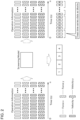
- the collected data related to the series of tasks collected by the data collector 21 is classified for each operation performed by the user (a reference operation) that corresponds to the task state.
- the tasks can be classified into four task states: aerial, contact, insertion, and completion.
- the task state SA is a state where the robot 11 is holding the workpiece 81 above the recess 82.
- the task state SB contact is a state where the workpiece 81 held by the robot 11 is in contact with a face on which the recess 82 is formed.
- the task state SC insertion is a state where the robot 11 is inserting the workpiece 81 into the recess 82 while holding the workpiece 81.
- the task state SD (completion) is a state where the workpiece 81 held by the robot 11 is completely inserted into the recess 82.
- the four task states are the series of the tasks performed by the robot 11 classified by process.
- the task state transitions in the following order: the task state SA (aerial), the task state SB (contact), the task state SC (insertion), and the task state SD (completion).
- the data learned by the screening model 41 may be, for example, a combination of any one of the task states, the next task state linked to that task state (that is, the task state into which that task state transitions next), and at least one pair of the state information and the user operation force linked to this state information. Accordingly, the screening model 41 can learn the order of the task states and the order of the corresponding operation forces.
- the machine learning of the screening model 41 can be referred to as clustering of the data.
- the above-mentioned task states SA, SB, SC, and SD are disclosed as typical examples and there can be many other different task states.
- a task state SA1 that corresponds to one pair of the state information and the operation force
- a task state SA2 that corresponds to another pair of the sate information and the operation force
- a task state SA3 that corresponds to another pair of the sate information and the operation force are collected.
- these task states SA1, SA2, and SA3 are different from each other.
- the task states SA1, SA2, and SA3 have common characteristics, they are to be classified into the same cluster (a cluster for the task state SA).
- the screening model 41 performs machine learning in such a way as described above that the time order of the outputs of the operation forces is reflected.
- the screening model 41 learns at least one pair of the state information and the operation force that corresponds to each of the task state SA, the task state SB, the task state SC, and the task state SD and learns the order of the tasks such as that the task state SB is next to the task state SA.
- the classification that reflects the time-series information of the operation forces can be performed using the screening model 41. That is, each of the operation forces linked to each of the task states can be reflected following the order of the tasks.
- the state information is the sensor information (for example, a task state, such as a position, a velocity, a force, moment, an image) detected by the motion sensor 11a, the force sensor 11b and the camera 11c as described above.
- This state information may include information calculated based on the sensor information (for example, a value that indicates changes in the sensor information over time from the past to the present).
- the screening model 41 which has completed a training phase, can infer and output the reference operation that corresponds to the state information that is linked to the time-series information of the collected data input, in an inference phase.
- the screening model 41 may output, for example, the information of the cluster that the reference operation belongs to.
- the screening model 41 can output the similarity between the operation information of the collected data input and the inferred reference operation.
- the similarity can be defined, for example, using the known Euclidean distance.
- the similarity output by the screening model 41 can be used as the evaluation value for evaluating the collected data.
- the task state transitions sequentially.
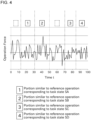
- the output of the similarity by the screening model 41 is performed with respect to the operation information in each range of a predetermined time. Specifically, when the evaluation value output by the screening model 41 with respect to the collected data in the predetermined time range exceeds a predetermined threshold, the training data selector 22 assigns a label (correspondence information) output by the screening model 41 that indicates the cluster that the reference operation belongs to to the collected data in that time range. On the other hand, when the evaluation value output by the screening model 41 is below the predetermined threshold, the training data selector 22 does not assign a label to that time range.
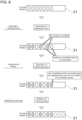
- FIG. 4 an example is shown where a label, numerical value "1", is assigned to the operation information because the operation information of the collected data in the predetermined time range is similar to the reference operation that corresponds to the task state SA. Similarly, the operation information in the time ranges labeled with the numerical value "2", “3", and "4" in FIG. 4 are similar to the reference operations that correspond to the task state SB, SC, and SD, respectively. FIG. 4 also shows time ranges that no labels were assigned to.
- the collected data in the time range that no labels were assigned to may be inappropriate to be used as the training data since the situation differs significantly from any of the task states that the screening model 41 learned. Therefore, the training data selector 22 does not adopt this time range as the training data. On the other hand, the training data selector 22 adopts the collected data in the time range assigned with the label as the training data.
- the label that the screening model 41 outputs needs not to be used for the automatic determination on whether the collected data should be adopted as the training data.
- the label may be presented as reference information when the user manually determines whether the collected data should be adopted as the training data.
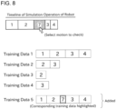
- FIG. 4 shows an example of a screen presented to the user.
- the operation information included in the collected data (for example, the operation force) is visually displayed in the form of a graph and the portion of data that includes the consecutive time-series information and is assigned with the same numerical label is displayed as one block. Accordingly, the user can determine whether the collected data should be adopted as the training data more easily.
- FIG. 5 shows an example of data to be adopted as the training data. In the example shown by FIG. 5 , all blocks in one of five pieces of the collected data are adopted as the training data while only some of the labeled blocks in other three pieces are adopted as the training data.
- the training data selector 22 includes a function of conducting evaluation on the selected training data.
- the criterion for the evaluation may be determined as desired. For example, whether the amount of the training data is sufficient, whether the amount of training data corresponding to some task states is sufficient, or the like is evaluated.
- the training data selector 22 If the training data satisfies the evaluation criterion, the training data selector 22 outputs the training data to the model constructor 23.
- the model constructor 23 utilizes machine learning (for example, supervised learning) to construct the learning model 31 used within the robot system 1.
- machine learning for example, supervised learning
- the learning model that has completed learning may be referred to as a trained model.
- the model constructor 23 uses the training data output from the training data selector 22 in order to construct to the learning model 31.
- the training data corresponds to the data selected from the collected data as described above. Therefore, similar to the collected data, the training data includes at least the surrounding environment data that reflects the task state of the robot 11 (that is, the state information) and the user operation force linked to this surrounding environment data (that is, the operation information).
- the learning model 31 is a neural network with a general configuration that includes, for example, an input layer, a hidden layer, and an output layer. Each layer includes more than one unit that simulate brain cells.
- the hidden layer is arranged between the input layer and the output layer and comprised of a suitable number of intermediate units.
- the state information (the training data) input into the learning model 31 by the model constructor 23 flows in the order of the input layer, the hidden layer, and the output layer.
- the number of the hidden layer is determined as appropriate.
- the format of the learning model 31 is not limited to this and it may be determined as desired.
- the data input to the input layer is the state information that reflects the above-mentioned surrounding environment data.
- the data output by the output layer is a result of the inference of the detected value obtained by the operation force detection sensor 13. Substantially, this indicates the inferred user operation force. Therefore, the data output by the output layer represents the operation by the user inferred by the learning model 31.
- Each input unit is connected to each intermediate unit by a path through which the information flows and each intermediate unit is connected to each output unit by a path through which the information flows.
- each path an influence of the information in the upstream unit on the information in the downstream unit (a weight) is set.
- the method for updating the learning model 31 is also not limited to the backward propagation of errors method.
- the learning model 31 may be updated by SOM (Self-organizing maps), which is a publicly known algorithm. Learning is achieved by continuously performing such processes.
- the model constructor 23 includes a function of evaluating the learning model 31 constructed.
- the criterion for this evaluation may be determined as desired. For example, when specific state information is input to the learning model 31, whether the user operation force as assumed is output is evaluated. Time and electric power required to perform the task may be evaluated by performing simulation using a 3D model of the robot 11 or the like.
- the model constructor 23 when the model constructor 23 operates the learning model 31 in the inference phase, it may be configured to also present the training data that is the basis for the inference that the leaning model 31 outputs. Accordingly, the leaning model 31 can be easily evaluated by a human or the like.
- each training data is plotted as a point in a multidimensional feature space.
- Each training data is assigned with an identifier that can uniquely identify the training data.
- the model constructor 23 calculates data that represent each cluster.
- this data may be referred to as nodes.
- data that correspond to the center of gravity of each cluster in the multidimensional space may be defined as the nodes.
- the portion of the training data that corresponds to the task state (block) that corresponds to the motion to be deleted becomes highlighted on the display.
- the method of highlighting is determined as desired.
- this training data is for performing a series of operations.
- the new training data includes an operation of slightly moving the workpiece 81 in various direction in a horizontal plane while keeping the workpiece 81 in contact with the face adjacent to the recess 82 before the operation OD in order to match the center of the workpiece 81 with the center of the recess 82.
- the plot of the new training data is added to the results of clustering in the above-mentioned multidimensional space. This corresponds to that the learning model 31 performs additional learning.
- FIG. 8 shows an example of the simulation in this case.
- the user operates the input apparatus to select a portion in a timeline that corresponds to the new motion. If, in response to this selection, a corresponding portion of the newly added training data is highlighted, the user can conclude that the stagnation of the motions in the simulation is resolved by the newly added training data.
- the effect of deleting or adding the content of what the learning model 31 learns is presented to the user.
- the user can edit what the learning model 31 learns with a sense of ease.
- the model constructor 23 outputs information indicating the satisfaction to the motion data recorder 24.
- the motion data recorder 24 transmits the output from the learning model 31 to the robot system 1 to make the robot 11 perform the autonomous operation and also records the motion data. This motion data is utilized, for example, to verify the autonomous operation of the robot 11.
- the motion data recorder 24 may be used during a subsequent actual operation, as described in detail below.
- the motion data recorder 24 can also record whether each motion is verified or not.
- a suitable memory unit included in the management apparatus 20 is used.
- the motion data recorder 24 is configured to store each plot in the multidimensional continuu linked to information whether it is verified.
- Each plot in clustering may be adopted as a node.
- the node is data representative of the cluster, as described above.
- Each data (plot) and each node correspond to an individual training element in the learning model 31.
- FIG. 9 schematically shows changes in the content stored in the motion data recorder 24 in relation to multiple phases that take place after the construction of the learning model 31.
- the state information at a certain point in time is input to the learning model 31. If the learning model 31 is constructed by clustering, the learning model 31 obtains a node with features similar to this state information.
- the learning model 31 includes more than one node that may be the basis for outputting the operation information during the inference phase.
- the nodes are schematically represented by small ellipses.
- the memory unit of the management apparatus 20 can record whether each node has been verified or not in a table format.
- the record may be in a format other than a table.
- a node for which it is recorded in the table that it has been verified may be referred to as a verified node and a node with no such record may be referred to as an unverified node.
- the learning model 31 When the operation information included in the data of the node is output as the result of inference, in the operation testing phase, the learning model 31 outputs information that identifies this node to the motion data recorder 24.
- this information may be referred to as node identifying information.
- the node identifying information may be, for example, without limitation, an identification number of the training data that corresponds to the node.
- the user monitors a tentative motion of the robot 11 based on the output from the learning model 31. The user determines whether there is any problem in the motion of the robot 11. For making this determination, the user can refer to the motion data recorded by the motion data recorder 24 by suitable means.
- the user gives an instruction of the completion of the verification by suitably operating an input apparatus of the management apparatus 20.
- This causes the motion data recorder 24 to update the above-mentioned table and record that the node that is output for the tentative motion has been verified.
- verified nodes are shown hatched.
- the learning model 31 outputs the node identifying information that identifies the obtained node to the motion data recorder 24. This node identifying information is output before the operation information included in the date of this node is output to the robot 11 as the result of the inference.
- the motion data recorder 24 determines whether the node from which the operation information is going to be output has been verified or not by referring to the above-mentioned table.
- the motion data recorder 24 controls the robot 11 to operate by the output of this node from the learning model 31.
- the motion data recorder 24 searches for a verified node similar to this unverified node.
- This search corresponds to a search for a verified node within a predetermined distance from the unverified node in the multidimensional feature space where the training data is plotted during clustering. This distance corresponds to similarity and it may be, for example, a Euclidean distance.
- the operation information that corresponds to the output from the verified node obtained by the search is compared with the operation information that corresponds to the output from the unverified node. This comparison can be done, for example, using the above-mentioned Euclidean distance.
- the motion data recorder 24 controls the robot 11 to perform by the output from the unverified node. It is preferable that the processes of the determination on whether the node is verified or not, the search for the verified node, the comparison between the outputs, and the like are performed within a term of the control cycle of the robot 11.
- the motion of the robot 11 based on the output from the unverified node is suitably monitored by the user. If the user determines that no problems have occurred, the user give an instruction of the completion of the verification to the management apparatus 20 by operating a suitable input apparatus, as in the operation testing phase. In response, the motion data recorder 24 updates the above-mentioned table and records that the relevant unverified node has been verified. As described above, in the present embodiment, the unverified node can be changed into the verified node during the operational phase in addition to the operation testing phase.
- the robot 11 does not have to operate based on the output from the unverified node.
- the robot 11 may be operated by the motion data recorder 24 based on an output obtained by compositing the outputs from the unverified node and the similar verified node.
- the composition of the outputs can be done, for example, by calculating the mean and the median of the outputs. If the prevention of the unexpected motion is emphasized, the motion data recorder 24 can perform control so that the output from the similar verified node completely substitute for the output from the unverified node.
- the motion data recorder 24 forcibly changes the output from the learning model 31 so that it becomes the predetermined output for the stable operation of the robot 11.
- the learning model 31 learns the operation of a master robot in a master-slave control that performs with zero difference between forces of the master robot and a slave robot.
- the motion data recorder 24 forcibly changes the user operation force that the learning model 31 outputs thereafter to zero and maintains it.
- the operational output from the master robot becomes zero, so that the slave robot operates in a direction with zero external force.
- the slave robot can transit to a stable state where zero external force is applied.
- the motion data recorder 24 may also be configured to output an alarm when that the learning model 31 tries to output the operation information based on the unverified node is detected.
- the alarm can be outputted, for example, by displaying it on the display, but it can be also reported by other means, for example, by a sound. Accordingly, the user can grasp the situation early.
- additional information linked to each node that may be the basis for the output of the operation information from the learning model 31 in the inference phase may be stored in the memory unit of the management apparatus 20.
- This additional information may be, for example, the information about whether the node is a new node added by the additional learning, whether the node includes an output that makes the robot 11 operate with a force greater than a predetermined force, or whether the workpiece 81 has damaged with the node before.
- These information can be recorded, for example, the user suitably operating the input apparatus of the management apparatus 20.
- the motion data recorder 24 presents the additional information to the user when outputting the above-mentioned alarm, for example.
- the presentation to the user is achieved, for example, by displaying it on the display. Accordingly, the user can obtain useful information about the unverified node and thus the user can easily make an appropriate determination regarding the operation of the learning model 31.
- the motion data recorder 24 forcibly changes the output from the learning model 31 to change the motion to a similar motion that is recorded as verified, for example.
- the motion data recorder 24 substantially functions as a model output controller and performs control on the output from the learning model 31 interferingly. Accordingly, an unexpected motion of the robot 11 can be prevented.
- the additional learning of the learning model 31 becomes required during the operational phase.
- the user operates the operating apparatus 12 to add new training data.
- a new node is added to the learning model 31.
- the added node is shown in a dashed line.
- the added node is recorded as an unverified node in the above-mentioned table.
- the phase returns to the operation testing phase or the operational phase.
- the record for this node in the table turns into verified from unverified.
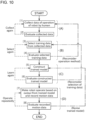
- the workflow from the construction of the learning model 31 to the operation thereof is divided into four phases: (A) obtainment of the collected data, (B) selection of the training data, (C) construction of the trained model, and (D) obtainment of the motion data.
- numbers [1] to [8] indicate a first process to an eighth process. Evaluation is conducted at each phase and if the evaluation criterion is not satisfied, the operation at that phase is performed again, as shown by dashed arrows in FIG. 10 . Only when the evaluation criterion is determined to be satisfied can the operation in the next phase be performed.
- the evaluation at each phase is conducted based on the assumption that the evaluation criterion is satisfied in the operation(s) upstream.
- the trained model constructed at phase (C) does not satisfy the evaluation criterion, it basically can be assumed that there is no problem with the upstream operation and a problem exists in the operation of constructing the trained model.
- the machine learning model can be smoothly constructed and operated.
- the trained model 31 can be constructed smoothly.
- the process in the fourth process, when the training data does not satisfy the evaluation criterion and a problem exists within the collected data, the process returns to the first process.
- the process in the sixth process, when the trained model does not satisfy the evaluation criterion and a problem exists within the training data, the process returns to the third process.
- the process may return to the second process instead of the first process and the process may return to the fourth process instead of the third process.
- the problem can be suitably resolved by starting the operation in that phase over again.
- the information including that operation is collected as the data.
- whether the collected data is appropriate as the training data is determined based on a predetermined rule and the results of the determination is presented to the user.
- This feature can be combined with at least the feature described in the above section (5).
- This feature can be combined with at least the feature described in the above section (1) or (2).
- the user can easily understand whether the collected data is appropriate as the training data or not. Also, the process can be simplified.
- the learning model 31 constructed in the fifth process operates in the inference phase
- the training data that is used for constructing the learning model 31 and is the basis of the output from the learning model 31 is specified and outputted.
- This feature can be combined with at least the feature described in any one of the above sections (1) to (3).
- the user when the user wants to edit the results of learning by the learning model 31 partly, for example, the user can grasp the range of the effect of the edit to a certain extent. Therefore, the user can adequately change or delete a part of what the learning model 31 learns.
- the robot 11 in a seventh process, is operated based on the output from the learning model 31 that satisfies the evaluation criterion to record the motion data.
- the motion data is evaluated and, when it does not satisfy a predetermined evaluation criterion, the robot 11 is operated again and the motion data is recorded again.
- the process when the motion data does not satisfy the evaluation criterion and a problem exists within the learning model 31, the process returns to the fifth process. However, the process may return to the sixth process instead of the fifth process.
- This feature can be combined with at least the feature described in the above section (5).
- the problem can be suitably resolved by starting the operation in that phase over again.
- the learning model 31 includes more than one training element. If the learning model 31 is constructed by clustering, for example, the node that is the data representing the cluster corresponds to the training element.
- the training element that is the basis for the motion is recorded as verified.
- the output from the trained model based on the training element that is unverified is changeable into a predetermined output or into the output based on the verified similar training element. This feature can be combined with at least the feature described in the above section (5) or (6).
- the target to be made perform the autonomous operation by the learning model 31 is the robot 11.
- This feature can be combined with at least the feature described in any one of the above sections (1) to (7).
- the learning model 31 for the autonomous operation of the robot 11 can be constructed smoothly.
- the seventh process and the eighth process in FIG. 10 may be omitted and the learning model 31 may be used immediately after the construction for the actual operation.
- the evaluation on the collected data shown in the second process may be conducted in a machine-learning-based manner instead of the so-called rule-based manner.
- the evaluation may be performed by a computer or by a human.
- the output apparatus used by the management apparatus 20 for various displays may be, for example, a liquid crystal display.
- a projector, a head-mounted display, or the like may also be used. If a head-mounted display is used, for example, the display may be performed using a known augmented reality (AR).
- AR augmented reality
- the operation information that the trained model infers may be, for example, the amount of changes in a velocity of the operation performed by the user on the operating apparatus 12 or in a position at which the user operates the operating apparatus 12, instead of the user operation force.
- the trained model may infer the relation between the state information and the control signal send to the robot 11.
- the constructed learning model 31 may be adopted with respect to a controlled machine other than the robot 11.
- circuitry or processing circuitry which includes general purpose processors, special purpose processors, integrated circuits, ASICs ("Application Specific Integrated Circuits"), conventional circuitry and/or combinations thereof which are configured or programmed to perform the disclosed functionality.
- Processors are considered processing circuitry or circuitry as they include transistors and other circuitry therein.
- the circuitry, units, or means are hardware that carry out or are programmed to perform the recited functionality.
- the hardware may be any hardware disclosed herein or otherwise known which is programmed or configured to carry out the recited functionality.
- the hardware is a processor which may be considered a type of circuitry
- the circuitry, means, or units are a combination of hardware and software, the software being used to configure the hardware and/or processor.
Landscapes
- Engineering & Computer Science (AREA)
- Theoretical Computer Science (AREA)
- Software Systems (AREA)
- Evolutionary Computation (AREA)
- Data Mining & Analysis (AREA)
- Medical Informatics (AREA)
- Computer Vision & Pattern Recognition (AREA)
- Physics & Mathematics (AREA)
- Computing Systems (AREA)
- General Engineering & Computer Science (AREA)
- General Physics & Mathematics (AREA)
- Mathematical Physics (AREA)
- Artificial Intelligence (AREA)
- Robotics (AREA)
- Mechanical Engineering (AREA)
- Manipulator (AREA)
Applications Claiming Priority (2)
| Application Number | Priority Date | Filing Date | Title |
|---|---|---|---|
| JP2021145070A JP7724114B2 (ja) | 2021-09-06 | 2021-09-06 | 学習済モデルの構築方法 |
| PCT/JP2022/033334 WO2023033179A1 (ja) | 2021-09-06 | 2022-09-05 | 学習済モデルの構築方法 |
Publications (2)
| Publication Number | Publication Date |
|---|---|
| EP4401014A1 true EP4401014A1 (de) | 2024-07-17 |
| EP4401014A4 EP4401014A4 (de) | 2025-10-08 |
Family
ID=85412493
Family Applications (1)
| Application Number | Title | Priority Date | Filing Date |
|---|---|---|---|
| EP22864761.6A Pending EP4401014A4 (de) | 2021-09-06 | 2022-09-05 | Verfahren zur konstruktion eines trainierten modells |
Country Status (5)
| Country | Link |
|---|---|
| US (1) | US20250045630A1 (de) |
| EP (1) | EP4401014A4 (de) |
| JP (2) | JP7724114B2 (de) |
| CN (1) | CN117957550A (de) |
| WO (1) | WO2023033179A1 (de) |
Families Citing this family (4)
| Publication number | Priority date | Publication date | Assignee | Title |
|---|---|---|---|---|
| JP7460366B2 (ja) * | 2019-12-27 | 2024-04-02 | 川崎重工業株式会社 | 訓練データ選別装置、ロボットシステム及び訓練データ選別方法 |
| WO2021168590A1 (en) * | 2020-02-27 | 2021-09-02 | University Of New Brunswick | Model predictive control systems and methods |
| JPWO2024224467A1 (de) * | 2023-04-25 | 2024-10-31 | ||
| US20250072979A1 (en) * | 2023-08-28 | 2025-03-06 | Auris Health, Inc. | Predictive Maintenance for Robotically Assisted Surgical System |
Family Cites Families (7)
| Publication number | Priority date | Publication date | Assignee | Title |
|---|---|---|---|---|
| US8306791B2 (en) * | 2009-12-21 | 2012-11-06 | United Technologies Corporation | Method and system for modeling the performance of a gas turbine engine |
| JP6886869B2 (ja) | 2017-06-09 | 2021-06-16 | 川崎重工業株式会社 | 動作予測システム及び動作予測方法 |
| US10981272B1 (en) * | 2017-12-18 | 2021-04-20 | X Development Llc | Robot grasp learning |
| WO2020142499A1 (en) * | 2018-12-31 | 2020-07-09 | Abb Schweiz Ag | Robot object learning system and method |
| JP2021086558A (ja) * | 2019-11-29 | 2021-06-03 | キヤノンメディカルシステムズ株式会社 | データ選別装置、学習装置及びプログラム |
| JP7460366B2 (ja) * | 2019-12-27 | 2024-04-02 | 川崎重工業株式会社 | 訓練データ選別装置、ロボットシステム及び訓練データ選別方法 |
| CN111310934B (zh) * | 2020-02-14 | 2023-10-17 | 北京百度网讯科技有限公司 | 一种模型生成方法、装置、电子设备和存储介质 |
-
2021
- 2021-09-06 JP JP2021145070A patent/JP7724114B2/ja active Active
-
2022
- 2022-09-05 WO PCT/JP2022/033334 patent/WO2023033179A1/ja not_active Ceased
- 2022-09-05 US US18/689,091 patent/US20250045630A1/en active Pending
- 2022-09-05 CN CN202280060412.7A patent/CN117957550A/zh active Pending
- 2022-09-05 EP EP22864761.6A patent/EP4401014A4/de active Pending
-
2025
- 2025-08-04 JP JP2025130023A patent/JP2025164965A/ja active Pending
Also Published As
| Publication number | Publication date |
|---|---|
| CN117957550A (zh) | 2024-04-30 |
| EP4401014A4 (de) | 2025-10-08 |
| JP2023038132A (ja) | 2023-03-16 |
| US20250045630A1 (en) | 2025-02-06 |
| WO2023033179A1 (ja) | 2023-03-09 |
| JP7724114B2 (ja) | 2025-08-15 |
| JP2025164965A (ja) | 2025-10-31 |
Similar Documents
| Publication | Publication Date | Title |
|---|---|---|
| EP4401014A1 (de) | Verfahren zur konstruktion eines trainierten modells | |
| CN111194452B (zh) | 动作预测系统及动作预测方法 | |
| JP6693938B2 (ja) | 外観検査装置 | |
| CN110355751B (zh) | 控制装置和机器学习装置 | |
| CN113412177B (zh) | 机器人控制装置、机器人系统以及机器人控制方法 | |
| JP2022171939A (ja) | 情報処理装置及び情報処理方法 | |
| JP7460366B2 (ja) | 訓練データ選別装置、ロボットシステム及び訓練データ選別方法 | |
| WO2021085345A1 (ja) | 機械学習データ生成装置、機械学習装置、作業システム、コンピュータプログラム、機械学習データ生成方法及び作業機械の製造方法 | |
| EP4052865A1 (de) | Informationsverarbeitungsgerät, robotersystem, informationsverarbeitungsverfahren, programm und aufzeichnungsmedium | |
| CN118269062A (zh) | 机械臂模仿学习示教数据的获取方法、装置、设备及介质 | |
| CN119398105B (zh) | 具身智能模型的运动规划的方法、训练方法以及系统 | |
| JP7759770B2 (ja) | ロボット制御装置、ロボットシステム及びロボット制御方法 | |
| US20250214234A1 (en) | Information processing apparatus, system, information processing method, method of manufacturing products, and recording medium | |
| KR20210070677A (ko) | 로봇의 이상 상태를 출력하는 방법 및 장치 | |
| JP2024101163A (ja) | 情報処理方法、情報処理装置、ロボットシステム、ロボットシステムの制御方法、物品の製造方法、プログラム及び記録媒体。 | |
| CN120347443A (zh) | 一种基于本体Petri网的多关节焊接机器人数字孪生控制方法 | |
| CN120773034A (zh) | 基于机器人视觉和触觉融合的数字孪生交互控制系统 | |
| CN119360364A (zh) | 一种烹饪设备的人工智能烹饪方法 | |
| CN116604535A (zh) | 应用于机器人产业链模块化设计的示教系统及方法 | |
| Hwang et al. | Autonomous vision-guided robot manipulation control | |
| JPH11259198A (ja) | 監視予測方法及びこれを用いた制御システム |
Legal Events
| Date | Code | Title | Description |
|---|---|---|---|
| STAA | Information on the status of an ep patent application or granted ep patent |
Free format text: STATUS: THE INTERNATIONAL PUBLICATION HAS BEEN MADE |
|
| PUAI | Public reference made under article 153(3) epc to a published international application that has entered the european phase |
Free format text: ORIGINAL CODE: 0009012 |
|
| STAA | Information on the status of an ep patent application or granted ep patent |
Free format text: STATUS: REQUEST FOR EXAMINATION WAS MADE |
|
| 17P | Request for examination filed |
Effective date: 20240404 |
|
| AK | Designated contracting states |
Kind code of ref document: A1 Designated state(s): AL AT BE BG CH CY CZ DE DK EE ES FI FR GB GR HR HU IE IS IT LI LT LU LV MC MK MT NL NO PL PT RO RS SE SI SK SM TR |
|
| DAV | Request for validation of the european patent (deleted) | ||
| DAX | Request for extension of the european patent (deleted) | ||
| A4 | Supplementary search report drawn up and despatched |
Effective date: 20250908 |
|
| RIC1 | Information provided on ipc code assigned before grant |
Ipc: G06N 20/00 20190101AFI20250902BHEP Ipc: B25J 13/00 20060101ALI20250902BHEP Ipc: B25J 9/16 20060101ALI20250902BHEP |