EP4400822A1 - Fiber optic actuator overload trip sensor - Google Patents
Fiber optic actuator overload trip sensor Download PDFInfo
- Publication number
- EP4400822A1 EP4400822A1 EP23218868.0A EP23218868A EP4400822A1 EP 4400822 A1 EP4400822 A1 EP 4400822A1 EP 23218868 A EP23218868 A EP 23218868A EP 4400822 A1 EP4400822 A1 EP 4400822A1
- Authority
- EP
- European Patent Office
- Prior art keywords
- actuator
- mirror
- state
- airplane
- change
- Prior art date
- Legal status (The legal status is an assumption and is not a legal conclusion. Google has not performed a legal analysis and makes no representation as to the accuracy of the status listed.)
- Granted
Links
Images



Classifications
-
- G—PHYSICS
- G01—MEASURING; TESTING
- G01L—MEASURING FORCE, STRESS, TORQUE, WORK, MECHANICAL POWER, MECHANICAL EFFICIENCY, OR FLUID PRESSURE
- G01L3/00—Measuring torque, work, mechanical power, or mechanical efficiency, in general
- G01L3/02—Rotary-transmission dynamometers
- G01L3/14—Rotary-transmission dynamometers wherein the torque-transmitting element is other than a torsionally-flexible shaft
- G01L3/1407—Rotary-transmission dynamometers wherein the torque-transmitting element is other than a torsionally-flexible shaft involving springs
- G01L3/1421—Rotary-transmission dynamometers wherein the torque-transmitting element is other than a torsionally-flexible shaft involving springs using optical transducers
-
- B—PERFORMING OPERATIONS; TRANSPORTING
- B64—AIRCRAFT; AVIATION; COSMONAUTICS
- B64D—EQUIPMENT FOR FITTING IN OR TO AIRCRAFT; FLIGHT SUITS; PARACHUTES; ARRANGEMENT OR MOUNTING OF POWER PLANTS OR PROPULSION TRANSMISSIONS IN AIRCRAFT
- B64D45/00—Aircraft indicators or protectors not otherwise provided for
-
- B—PERFORMING OPERATIONS; TRANSPORTING
- B64—AIRCRAFT; AVIATION; COSMONAUTICS
- B64D—EQUIPMENT FOR FITTING IN OR TO AIRCRAFT; FLIGHT SUITS; PARACHUTES; ARRANGEMENT OR MOUNTING OF POWER PLANTS OR PROPULSION TRANSMISSIONS IN AIRCRAFT
- B64D45/00—Aircraft indicators or protectors not otherwise provided for
- B64D45/0005—Devices specially adapted to indicate the position of a movable element of the aircraft, e.g. landing gear
-
- B—PERFORMING OPERATIONS; TRANSPORTING
- B64—AIRCRAFT; AVIATION; COSMONAUTICS
- B64F—GROUND OR AIRCRAFT-CARRIER-DECK INSTALLATIONS SPECIALLY ADAPTED FOR USE IN CONNECTION WITH AIRCRAFT; DESIGNING, MANUFACTURING, ASSEMBLING, CLEANING, MAINTAINING OR REPAIRING AIRCRAFT, NOT OTHERWISE PROVIDED FOR; HANDLING, TRANSPORTING, TESTING OR INSPECTING AIRCRAFT COMPONENTS, NOT OTHERWISE PROVIDED FOR
- B64F5/00—Designing, manufacturing, assembling, cleaning, maintaining or repairing aircraft, not otherwise provided for; Handling, transporting, testing or inspecting aircraft components, not otherwise provided for
- B64F5/60—Testing or inspecting aircraft components or systems
-
- G—PHYSICS
- G01—MEASURING; TESTING
- G01D—MEASURING NOT SPECIALLY ADAPTED FOR A SPECIFIC VARIABLE; ARRANGEMENTS FOR MEASURING TWO OR MORE VARIABLES NOT COVERED IN A SINGLE OTHER SUBCLASS; TARIFF METERING APPARATUS; MEASURING OR TESTING NOT OTHERWISE PROVIDED FOR
- G01D5/00—Mechanical means for transferring the output of a sensing member; Means for converting the output of a sensing member to another variable where the form or nature of the sensing member does not constrain the means for converting; Transducers not specially adapted for a specific variable
- G01D5/26—Mechanical means for transferring the output of a sensing member; Means for converting the output of a sensing member to another variable where the form or nature of the sensing member does not constrain the means for converting; Transducers not specially adapted for a specific variable characterised by optical transfer means, i.e. using infrared, visible, or ultraviolet light
- G01D5/266—Mechanical means for transferring the output of a sensing member; Means for converting the output of a sensing member to another variable where the form or nature of the sensing member does not constrain the means for converting; Transducers not specially adapted for a specific variable characterised by optical transfer means, i.e. using infrared, visible, or ultraviolet light by interferometric means
-
- G—PHYSICS
- G01—MEASURING; TESTING
- G01L—MEASURING FORCE, STRESS, TORQUE, WORK, MECHANICAL POWER, MECHANICAL EFFICIENCY, OR FLUID PRESSURE
- G01L3/00—Measuring torque, work, mechanical power, or mechanical efficiency, in general
- G01L3/02—Rotary-transmission dynamometers
- G01L3/04—Rotary-transmission dynamometers wherein the torque-transmitting element comprises a torsionally-flexible shaft
- G01L3/08—Rotary-transmission dynamometers wherein the torque-transmitting element comprises a torsionally-flexible shaft involving optical means for indicating
-
- B—PERFORMING OPERATIONS; TRANSPORTING
- B64—AIRCRAFT; AVIATION; COSMONAUTICS
- B64D—EQUIPMENT FOR FITTING IN OR TO AIRCRAFT; FLIGHT SUITS; PARACHUTES; ARRANGEMENT OR MOUNTING OF POWER PLANTS OR PROPULSION TRANSMISSIONS IN AIRCRAFT
- B64D45/00—Aircraft indicators or protectors not otherwise provided for
- B64D45/0005—Devices specially adapted to indicate the position of a movable element of the aircraft, e.g. landing gear
- B64D2045/001—Devices specially adapted to indicate the position of a movable element of the aircraft, e.g. landing gear for indicating symmetry of flaps deflection
-
- B—PERFORMING OPERATIONS; TRANSPORTING
- B64—AIRCRAFT; AVIATION; COSMONAUTICS
- B64D—EQUIPMENT FOR FITTING IN OR TO AIRCRAFT; FLIGHT SUITS; PARACHUTES; ARRANGEMENT OR MOUNTING OF POWER PLANTS OR PROPULSION TRANSMISSIONS IN AIRCRAFT
- B64D45/00—Aircraft indicators or protectors not otherwise provided for
- B64D2045/0085—Devices for aircraft health monitoring, e.g. monitoring flutter or vibration
Definitions
- Embodiments of the present disclosure relate to airplane operations and, more particular, to a system and method for detecting an overload torque at a slat and/or a flap on a wing of an airplane.
- An airplane wing generally includes a slat at its forward surface and a flap at its anterior to perform different flight operations.
- An actuator is used to control a position of the slat and/or the flap.
- an over-torque indicator on the actuator is released.
- the actuator is a mechanical actuator that can be inspected only when the airplane is safely on the ground.
- the effects of an over-torque condition can be critical to flight of the airplane. Therefore, there is a need for an over-torque indicator that can relay an over-torque condition to the pilot while the airplane is in flight.
- a method of determining a state of an actuator in an airplane includes reflecting incident light off of a mirror coupled to the actuator to create a reflected light, wherein a location of the mirror is dependent on the state of the actuator, moving the mirror upon a change in the state of the actuator, detecting a change in a parameter of the reflected light generated by moving of the mirror, and determining the state of the actuator based on the change in the parameter.
- the mirror is coupled to the actuator via a spring and the spring moves the mirror based on the state of the actuator.
- the method further includes translating a wedge via the spring to move the mirror.
- the spring is held in a non-equilibrium position by a mechanical trip indicator under normal operation of the actuator and is released by the mechanical trip indicator to relax to its equilibrium position when the actuator is over-torqued.
- the parameter of the reflected light is a phase of the reflected light.
- the method further includes detecting a change in the phase using an interferometer.
- the method further includes controlling an operation of the airplane based on the state of the actuator.
- the method further includes controlling at least one of: (i) a slat of the airplane; and (ii) a flap of the airplane.
- an apparatus for detecting a state of an actuator in an airplane includes a mirror coupled to the actuator, wherein a location of the mirror is dependent on the state of the actuator, a shaft for moving the mirror upon a change in the state of the actuator, and a processor.
- the processor is configured to project incident light onto the mirror, receive reflected light from the mirror, detect a change in a parameter of the reflected light generated by moving of the mirror, and determine the state of the actuator based on the change in the parameter.
- the apparatus further includes a spring coupled to the shaft, wherein the spring moves the shaft based on the state of the actuator.
- the apparatus further includes a wedge coupled to the shaft, wherein the wedges moves with the shaft to move the mirror.
- the spring is held in a non-equilibrium position by a mechanical trip indicator under normal operation of the actuator and is released by the mechanical trip indicator to relax to its equilibrium position when the actuator is over-torqued.
- the parameter of the reflected light is a phase of the reflected light.
- the apparatus further includes an interferometer configured to detect a change in the phase.
- the processor is further configured to control at least one of: (i) an operation of the airplane based on the state of the actuator; (ii) a slat of the airplane; and (iii) a flap of the airplane.
- the airplane 100 includes a fuselage 102 and wings 104.
- Each wing 104 includes a slat 106 and a flap 108.
- a wing 104 can include a plurality of slats and/or a plurality of flaps 108.
- a slat 106 is a surface on a forward or leading edge of the wing 104. When deployed, a slat 106 allows the wing 104 to operate at a higher angle of attack.
- a flap 108 is a surface on a trailing edge of the wing 104 and is used to increase a drag on the airplane 100 when deployed.
- a cockpit 110 sends signals for controlling the operation of the slats 106 and the flaps.
- the cockpit 110 can include a controller including a processor for controlling various operations of the airplane 100.
- the cockpit 110 sends an optical slat/flap command along one or more optical fibers.
- a slat control optical fiber 112 extends along a wing 104 to one or more of the slats 106 and a flap control optical fiber 114 extends along a wing 104 to one or more of the flaps 108.
- FIG. 2 shows a schematic diagram 200 of an optical communication system within the airplane 100, in an embodiment.
- An optical fiber 202 extends between a first converter 204 and a second converter 206.
- the first converter 204 converts an electrical signal to an optical signal and converts an optical signal to an electrical signal.
- the second converter 206 converts an electrical signal to an optical signal and converts an optical signal to an electrical signal.
- the first converter 204 can be located at a cockpit 110 of the airplane 100 or at the controller.
- the second converter 206 can be at or near an actuator of one of the slats 106 or flaps 108.
- a command signal (e.g., generated at the controller) is received at the first converter 204, which converts the command signal to an optical signal that is sent from the first converter 204 over the optical fiber 202 to the second converter 206.
- the second converter 206 converts the optical signal back to an electrical signal which is used as a local control circuit 210 to control the operation of the slat 106 and/or flaps 108.
- the local control circuit 210 can generate an electrical signal.
- the second converter 206 converts the electrical signal to an optical signal that is sent over the optical fiber 202 to the first converter 204.
- the first converter 204 converts the optical signal back to an electrical signal which is sent to the controller 208.
- the controller 208 can used the signal to control various operations of the airplane 100, such as controlling operation of other slat 106 and/or flaps 108, etc.
- the controller 208 can response to the signal by generating a message at a screen, an audio signal, etc.
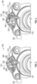
- FIG. 3 shows a side view of an actuator 300 under normal operations including a trip indictor in a non-tripped state.
- FIG. 4 shows a side view of the actuator 300 under an over-torqued condition including the trip indicator in a tripped state.
- the actuator 300 includes a mechanical trip indicator 302 that includes a mechanical trip member 304 that changes its position when the actuator 300 is over-torqued.
- the mechanical trip member 304 is a poppet disposed in a passage.
- the poppet that extends from the passage.
- the poppet recedes into the passage.
- a spring 306 is fastened at one end to an anchor point 308 of the actuator 300 and is held in a first position (i.e., away from its equilibrium position) by the poppet when the poppet is extended from the passage (i.e., during normal operation).
- the poppet recedes in the passage i.e., during over-torquing
- the actuator 300 includes an optical device 310 coupled to the spring 306 and thus coupled to the mechanical trip member 304.
- the optical device 310 includes a body 312 having a cavity (shown in FIG. 5 ) and a shaft 314 that is moveable in and out of the cavity.
- the shaft 314 is attached to the spring 306 such that the shaft 314 moves when the spring moves between the non-tripped state ( FIG. 3 ) and the tripped state ( FIG. 4 ).
- the optical interrogator 320 can includes a light source or laser for generating a first beam of light (e.g., incident light) and a detector for receiving and detecting a second beam of light (e.g., reflected light).
- the optical interrogator 320 can also include a processor that controls operation of the light source and detector and performs various calculations to determine a change in a parameter of the reflected light with respect to the incident light.
- the processor can also perform calculations to determine a state of the actuator based on the change in the parameter.
- the parameter is a phase of the light.
- the optical interrogator 320 sends light into the body 312 via the optical fiber 316 and receives a reflection of the light from the body 312 that is reflected back along the optical fiber 316.
- the actuator 300 changes from a non-tripped state ( FIG. 3 ) to a tripped state ( FIG. 4 )
- the poppet is pulled into its passage, thereby releasing the spring allowing the spring to relax to its equilibrium position (the second position).
- the spring relaxes, it moves the shaft 314.
- the shaft affects a phase of the reflected light.
- the optical interrogator 320 can record this change of phase and can determine that the actuator is over-torqued by detecting this change of phase.
- FIG. 5 shows a detailed view 500 of the optical device 310, in an embodiment.
- the optical device 310 is a linear position transducer.
- the optical device 310 includes a housing 502 forming a cavity 504 extending along a longitudinal axis from a first end 506 to a second end 508.
- the shaft 314 is located at the second end 508 and is slidable along a translation direction 510 parallel to the longitudinal axis.
- a wedge 512 is located within the cavity 504 and is mechanically coupled to the shaft 314.
- the wedge 512 can be made of a birefringent material.
- the wedge 512 has a maximum thickness d s at an end distal from the shaft 314 and a thickness of the wedge changes linearly along its length.
- a reflection polarizer 514 or mirror is disposed at a location within the cavity 504.
- the mirror is a planar mirror in which the plane of the mirror perpendicular or substantially perpendicular to the longitudinal axis to the cavity 504.
- the plane of the mirror is also perpendicular or substantially perpendicular to the direction of propagation of light within the cavity 504.
- the position or location of the mirror along the longitudinal axis of the cavity 504 and/or the orientation of the mirror within the cavity 504 is affected by the position of the wedge 512.
- the wedge 512 makes contact with a bottom edge 516 of the mirror while the top edge 518 is attached to the housing 502.
- the wedge 512 As the shaft 314 moves, the wedge 512 is moved along the translation direction, thereby changing the contact point between the wedge 512 and the mirror.
- the mirror tilts as the contact point changes. For example, as the wedge moves toward the first end 506, the mirror can tilt such that its bottom edge 516 is closer to the first end 506 than the top edge 518.
- the mirror is attached only to the wedge 512 and moves along the longitudinal axis along with the wedge 512.
- An end of the optical fiber 316 is placed at the opening of the first end 506.
- incident light 520 is introduced into the cavity 504 at the first end 506 by the optical fiber 316 and propagates along the longitudinal axis in the direction of the second end 508.
- the incident light reflects off the mirror to form reflected light 522 which is returned to the optical fiber 316.
- the mirror moves or is tilted, it introduces a phase change into the reflected light 522. This phase change ⁇ s is shown in Eq.
- ⁇ s 2 Bd s
- d s the maximum thickness of the wedge 512
- B a phase angle associated with a difference between a first position of the mirror (a non-tripped position) and a second position of the mirror (a tripped position).
- the reflected light 522 is returned to the optical interrogator 320 via the optical fiber 316.
- the optical interrogator 320 can include an interferometer, with the optical fiber 316 and mirror acting as an arm of the interferometer. The optical interrogator 320 detects the change in phase caused by the motion of the mirror.
- the optical interrogator 320 can determine whether the actuator 300 is in an over-torqued state or in a normal operating state by measured the phase shift of the light, or lack thereof.
Landscapes
- Engineering & Computer Science (AREA)
- Aviation & Aerospace Engineering (AREA)
- Physics & Mathematics (AREA)
- General Physics & Mathematics (AREA)
- Manufacturing & Machinery (AREA)
- Transportation (AREA)
- Mechanical Light Control Or Optical Switches (AREA)
- Photometry And Measurement Of Optical Pulse Characteristics (AREA)
- Pretreatment Of Seeds And Plants (AREA)
Abstract
Description
- Embodiments of the present disclosure relate to airplane operations and, more particular, to a system and method for detecting an overload torque at a slat and/or a flap on a wing of an airplane.
- An airplane wing generally includes a slat at its forward surface and a flap at its anterior to perform different flight operations. An actuator is used to control a position of the slat and/or the flap. When an actuator experiences an over-torque condition, an over-torque indicator on the actuator is released. The actuator is a mechanical actuator that can be inspected only when the airplane is safely on the ground. However, the effects of an over-torque condition can be critical to flight of the airplane. Therefore, there is a need for an over-torque indicator that can relay an over-torque condition to the pilot while the airplane is in flight.
- According to an embodiment, a method of determining a state of an actuator in an airplane is disclosed. The method includes reflecting incident light off of a mirror coupled to the actuator to create a reflected light, wherein a location of the mirror is dependent on the state of the actuator, moving the mirror upon a change in the state of the actuator, detecting a change in a parameter of the reflected light generated by moving of the mirror, and determining the state of the actuator based on the change in the parameter.
- In addition to one or more of the features described above, the mirror is coupled to the actuator via a spring and the spring moves the mirror based on the state of the actuator.
- In addition to one or more of the features described above, the method further includes translating a wedge via the spring to move the mirror.
- In addition to one or more of the features described above, the spring is held in a non-equilibrium position by a mechanical trip indicator under normal operation of the actuator and is released by the mechanical trip indicator to relax to its equilibrium position when the actuator is over-torqued.
- In addition to one or more of the features described above, the parameter of the reflected light is a phase of the reflected light.
- In addition to one or more of the features described above, the method further includes detecting a change in the phase using an interferometer.
- In addition to one or more of the features described above, the method further includes controlling an operation of the airplane based on the state of the actuator.
- In addition to one or more of the features described above, the method further includes controlling at least one of: (i) a slat of the airplane; and (ii) a flap of the airplane.
- According to another embodiment, an apparatus for detecting a state of an actuator in an airplane is disclosed. The apparatus includes a mirror coupled to the actuator, wherein a location of the mirror is dependent on the state of the actuator, a shaft for moving the mirror upon a change in the state of the actuator, and a processor. The processor is configured to project incident light onto the mirror, receive reflected light from the mirror, detect a change in a parameter of the reflected light generated by moving of the mirror, and determine the state of the actuator based on the change in the parameter.
- In addition to one or more of the features described above, the apparatus further includes a spring coupled to the shaft, wherein the spring moves the shaft based on the state of the actuator.
- In addition to one or more of the features described above, the apparatus further includes a wedge coupled to the shaft, wherein the wedges moves with the shaft to move the mirror.
- In addition to one or more of the features described above, the spring is held in a non-equilibrium position by a mechanical trip indicator under normal operation of the actuator and is released by the mechanical trip indicator to relax to its equilibrium position when the actuator is over-torqued.
- In addition to one or more of the features described above, the parameter of the reflected light is a phase of the reflected light.
- In addition to one or more of the features described above, the apparatus further includes an interferometer configured to detect a change in the phase.
- In addition to one or more of the features described above, the processor is further configured to control at least one of: (i) an operation of the airplane based on the state of the actuator; (ii) a slat of the airplane; and (iii) a flap of the airplane.
- The following descriptions should not be considered limiting in any way. With reference to the accompanying drawings, like elements are numbered alike:
-
FIG. 1 shows an airplane in a plan view; -
FIG. 2 shows a schematic diagram of an optical communication system within the airplane, in an embodiment; -
FIG. 3 shows a side view of an actuator under normal operations including a trip indictor in a non-tripped state; -
FIG. 4 shows a side view of the actuator under an over-torqued condition including the trip indicator in a tripped state; and -
FIG. 5 shows a detailed view of the optical device, in an embodiment. - A detailed description of one or more embodiments of the disclosed apparatus and method are presented herein by way of exemplification and not limitation with reference to the Figures.
- With reference now to
FIG. 1 , anairplane 100 is shown in a plan view. Theairplane 100 includes afuselage 102 andwings 104. Eachwing 104 includes aslat 106 and aflap 108. In various embodiments, awing 104 can include a plurality of slats and/or a plurality offlaps 108. Aslat 106 is a surface on a forward or leading edge of thewing 104. When deployed, aslat 106 allows thewing 104 to operate at a higher angle of attack. Aflap 108 is a surface on a trailing edge of thewing 104 and is used to increase a drag on theairplane 100 when deployed. - A
cockpit 110 sends signals for controlling the operation of theslats 106 and the flaps. Thecockpit 110 can include a controller including a processor for controlling various operations of theairplane 100. In various embodiments, thecockpit 110 sends an optical slat/flap command along one or more optical fibers. As shown inFIG. 1 , a slat controloptical fiber 112 extends along awing 104 to one or more of theslats 106 and a flap controloptical fiber 114 extends along awing 104 to one or more of theflaps 108. -
FIG. 2 shows a schematic diagram 200 of an optical communication system within theairplane 100, in an embodiment. Anoptical fiber 202 extends between afirst converter 204 and asecond converter 206. Thefirst converter 204 converts an electrical signal to an optical signal and converts an optical signal to an electrical signal. Similarly, thesecond converter 206 converts an electrical signal to an optical signal and converts an optical signal to an electrical signal. Thefirst converter 204 can be located at acockpit 110 of theairplane 100 or at the controller. Thesecond converter 206 can be at or near an actuator of one of theslats 106 orflaps 108. To control theslats 106 and/orflaps 108, a command signal (e.g., generated at the controller) is received at thefirst converter 204, which converts the command signal to an optical signal that is sent from thefirst converter 204 over theoptical fiber 202 to thesecond converter 206. Thesecond converter 206 converts the optical signal back to an electrical signal which is used as alocal control circuit 210 to control the operation of theslat 106 and/orflaps 108. For communication in the other direction, thelocal control circuit 210 can generate an electrical signal. Thesecond converter 206 converts the electrical signal to an optical signal that is sent over theoptical fiber 202 to thefirst converter 204. Thefirst converter 204 converts the optical signal back to an electrical signal which is sent to thecontroller 208. Thecontroller 208 can used the signal to control various operations of theairplane 100, such as controlling operation ofother slat 106 and/orflaps 108, etc. In addition, thecontroller 208 can response to the signal by generating a message at a screen, an audio signal, etc. - Reference is now made to
FIGS. 3 and 4 to discuss operation of and actuator for a slat or flap and an associated trip indicator.FIG. 3 shows a side view of anactuator 300 under normal operations including a trip indictor in a non-tripped state.FIG. 4 shows a side view of theactuator 300 under an over-torqued condition including the trip indicator in a tripped state. - The
actuator 300 includes amechanical trip indicator 302 that includes amechanical trip member 304 that changes its position when theactuator 300 is over-torqued. In an embodiment, themechanical trip member 304 is a poppet disposed in a passage. During normal operations of theactuator 300, the poppet that extends from the passage. When theactuator 300 is over-torqued, the poppet recedes into the passage. Aspring 306 is fastened at one end to ananchor point 308 of theactuator 300 and is held in a first position (i.e., away from its equilibrium position) by the poppet when the poppet is extended from the passage (i.e., during normal operation). When the poppet recedes in the passage (i.e., during over-torquing), it released thespring 306, thereby allowing thespring 306 to move to a second position (i.e., its equilibrium position). - The
actuator 300 includes anoptical device 310 coupled to thespring 306 and thus coupled to themechanical trip member 304. Theoptical device 310 includes abody 312 having a cavity (shown inFIG. 5 ) and ashaft 314 that is moveable in and out of the cavity. Theshaft 314 is attached to thespring 306 such that theshaft 314 moves when the spring moves between the non-tripped state (FIG. 3 ) and the tripped state (FIG. 4 ). - An
optical fiber 316 extends between thebody 312 of theoptical device 310 to anoptical interrogator 320. Theoptical interrogator 320 can includes a light source or laser for generating a first beam of light (e.g., incident light) and a detector for receiving and detecting a second beam of light (e.g., reflected light). Theoptical interrogator 320 can also include a processor that controls operation of the light source and detector and performs various calculations to determine a change in a parameter of the reflected light with respect to the incident light. The processor can also perform calculations to determine a state of the actuator based on the change in the parameter. In various embodiments, the parameter is a phase of the light. - The
optical interrogator 320 sends light into thebody 312 via theoptical fiber 316 and receives a reflection of the light from thebody 312 that is reflected back along theoptical fiber 316. When the actuator 300 changes from a non-tripped state (FIG. 3 ) to a tripped state (FIG. 4 ), the poppet is pulled into its passage, thereby releasing the spring allowing the spring to relax to its equilibrium position (the second position). As the spring relaxes, it moves theshaft 314. As discussed with respect toFIG. 5 , the shaft affects a phase of the reflected light. Thus, theoptical interrogator 320 can record this change of phase and can determine that the actuator is over-torqued by detecting this change of phase. -
FIG. 5 shows adetailed view 500 of theoptical device 310, in an embodiment. In an embodiment, theoptical device 310 is a linear position transducer. Theoptical device 310 includes ahousing 502 forming acavity 504 extending along a longitudinal axis from afirst end 506 to asecond end 508. Theshaft 314 is located at thesecond end 508 and is slidable along atranslation direction 510 parallel to the longitudinal axis. Awedge 512 is located within thecavity 504 and is mechanically coupled to theshaft 314. In one embodiment, thewedge 512 can be made of a birefringent material. Thewedge 512 has a maximum thickness ds at an end distal from theshaft 314 and a thickness of the wedge changes linearly along its length. - A
reflection polarizer 514 or mirror is disposed at a location within thecavity 504. In an embodiment, the mirror is a planar mirror in which the plane of the mirror perpendicular or substantially perpendicular to the longitudinal axis to thecavity 504. The plane of the mirror is also perpendicular or substantially perpendicular to the direction of propagation of light within thecavity 504. The position or location of the mirror along the longitudinal axis of thecavity 504 and/or the orientation of the mirror within thecavity 504 is affected by the position of thewedge 512. In one embodiment, thewedge 512 makes contact with abottom edge 516 of the mirror while thetop edge 518 is attached to thehousing 502. As theshaft 314 moves, thewedge 512 is moved along the translation direction, thereby changing the contact point between thewedge 512 and the mirror. The mirror tilts as the contact point changes. For example, as the wedge moves toward thefirst end 506, the mirror can tilt such that itsbottom edge 516 is closer to thefirst end 506 than thetop edge 518. In another embodiment, the mirror is attached only to thewedge 512 and moves along the longitudinal axis along with thewedge 512. - An end of the
optical fiber 316 is placed at the opening of thefirst end 506. To operate theoptical device 310, incident light 520 is introduced into thecavity 504 at thefirst end 506 by theoptical fiber 316 and propagates along the longitudinal axis in the direction of thesecond end 508. The incident light reflects off the mirror to form reflected light 522 which is returned to theoptical fiber 316. As the mirror moves or is tilted, it introduces a phase change into the reflected light 522. This phase change δs is shown in Eq. (1):
wedge 512 and B is a phase angle associated with a difference between a first position of the mirror (a non-tripped position) and a second position of the mirror (a tripped position). The reflected light 522 is returned to theoptical interrogator 320 via theoptical fiber 316. In various embodiments, theoptical interrogator 320 can include an interferometer, with theoptical fiber 316 and mirror acting as an arm of the interferometer. Theoptical interrogator 320 detects the change in phase caused by the motion of the mirror. Since the movement of the mirror is caused by movement of theshaft 314 which is due to movement of thespring 306, which is due to the movement of themechanical trip member 304, theoptical interrogator 320 can determine whether theactuator 300 is in an over-torqued state or in a normal operating state by measured the phase shift of the light, or lack thereof. - The term "about" is intended to include the degree of error associated with measurement of the particular quantity based upon the equipment available at the time of filing the application.
- The terminology used herein is for the purpose of describing particular embodiments only and is not intended to be limiting of the present disclosure. As used herein, the singular forms "a", "an" and "the" are intended to include the plural forms as well, unless the context clearly indicates otherwise. It will be further understood that the terms "comprises" and/or "comprising," when used in this specification, specify the presence of stated features, integers, steps, operations, elements, and/or components, but do not preclude the presence or addition of one or more other features, integers, steps, operations, element components, and/or groups thereof.
- While the present disclosure has been described with reference to an exemplary embodiment or embodiments, it will be understood by those skilled in the art that various changes may be made and equivalents may be substituted for elements thereof without departing from the scope of the present disclosure. In addition, many modifications may be made to adapt a particular situation or material to the teachings of the present disclosure without departing from the essential scope thereof. Therefore, it is intended that the present disclosure not be limited to the particular embodiment disclosed as the best mode contemplated for carrying out this present disclosure, but that the present disclosure will include all embodiments falling within the scope of the claims.
Claims (15)
- A method of determining a state of an actuator in an airplane, comprising:reflecting incident light off of a mirror coupled to the actuator to create a reflected light, wherein a location of the mirror is dependent on the state of the actuator;moving the mirror upon a change in the state of the actuator;detecting a change in a parameter of the reflected light generated by moving of the mirror; anddetermining the state of the actuator based on the change in the parameter.
- The method of claim 1, wherein the mirror is coupled to the actuator via a spring, wherein the spring moves the mirror based on the state of the actuator.
- The method of claim 2, further comprising translating a wedge via the spring to move the mirror.
- The method of claim 2 or 3, wherein the spring is held in a non-equilibrium position by a mechanical trip indicator under normal operation of the actuator and is released by the mechanical trip indicator to relax to its equilibrium position when the actuator is over-torqued.
- The method of any preceding claim, wherein the parameter of the reflected light is a phase of the reflected light.
- The method of claim 5, further comprising detecting the change in the phase using an interferometer.
- The method of any preceding claim, further comprising controlling an operation of the airplane based on the state of the actuator.
- The method of any preceding claim, further comprising controlling at least one of: (i) a slat of the airplane; and (ii) a flap of the airplane.
- An apparatus for detecting a state of an actuator in an airplane, comprising:a mirror coupled to the actuator, wherein a location of the mirror is dependent on the state of the actuator;a shaft for moving the mirror upon a change in the state of the actuator;a processor configured to:project incident light onto the mirror;receive reflected light from the mirror;detect a change in a parameter of the reflected light generated by moving of the mirror; anddetermine the state of the actuator based on the change in the parameter.
- The apparatus of claim 9, further comprising a spring coupled to the shaft, wherein the spring moves the shaft based on the state of the actuator.
- The apparatus of claim 10, further comprising a wedge coupled to the shaft, wherein the wedges moves with the shaft to move the mirror.
- The apparatus of claim 10 or 11, wherein the spring is held in a non-equilibrium position by a mechanical trip indicator under normal operation of the actuator and is released by the mechanical trip indicator to relax to its equilibrium position when the actuator is over-torqued.
- The apparatus of any of claims 9 to 12, wherein the parameter of the reflected light is a phase of the reflected light.
- The apparatus of claim 13, further comprising an interferometer configured to detect the change in the phase.
- The apparatus of any of claims 9 to 14, wherein the processor is further configured to control at least one of (i) an operation of the airplane based on the state of the actuator; (ii) a slat of the airplane; and (iii) a flap of the airplane.
Applications Claiming Priority (1)
| Application Number | Priority Date | Filing Date | Title |
|---|---|---|---|
| US18/154,503 US12337990B2 (en) | 2023-01-13 | 2023-01-13 | Fiber optic actuator overload trip sensor |
Publications (2)
| Publication Number | Publication Date |
|---|---|
| EP4400822A1 true EP4400822A1 (en) | 2024-07-17 |
| EP4400822B1 EP4400822B1 (en) | 2025-11-19 |
Family
ID=89224680
Family Applications (1)
| Application Number | Title | Priority Date | Filing Date |
|---|---|---|---|
| EP23218868.0A Active EP4400822B1 (en) | 2023-01-13 | 2023-12-20 | Fiber optic actuator overload trip sensor |
Country Status (3)
| Country | Link |
|---|---|
| US (1) | US12337990B2 (en) |
| EP (1) | EP4400822B1 (en) |
| CA (1) | CA3223432A1 (en) |
Families Citing this family (1)
| Publication number | Priority date | Publication date | Assignee | Title |
|---|---|---|---|---|
| US12337990B2 (en) * | 2023-01-13 | 2025-06-24 | Hamilton Sundstrand Corporation | Fiber optic actuator overload trip sensor |
Citations (2)
| Publication number | Priority date | Publication date | Assignee | Title |
|---|---|---|---|---|
| US20190337635A1 (en) * | 2018-05-07 | 2019-11-07 | Hamilton Sundstrand Corporation | Rfid actuator over-torque indicator |
| US11385097B1 (en) * | 2018-05-31 | 2022-07-12 | Amazon Technologies, Inc. | Optical vibration measurement systems for aerial vehicles |
Family Cites Families (13)
| Publication number | Priority date | Publication date | Assignee | Title |
|---|---|---|---|---|
| DE10308301B3 (en) * | 2003-02-26 | 2004-07-15 | Liebherr-Aerospace Lindenberg Gmbh | Aircraft landing flaps operating drive with overload protection provided by electrical load sensor at point of transmission of central drive energy to each individual flap body operating drive |
| DE102004044961B4 (en) | 2004-09-16 | 2007-02-01 | Liebherr-Aerospace Lindenberg Gmbh | Device for detecting synchronization errors of high-lift surfaces on aircraft |
| US8022835B2 (en) * | 2005-10-24 | 2011-09-20 | Nathan John Coleman | Optic system using spectral character shift for communication between optic input devices and reader devices for control systems and sensors for pressure, force, displacement, or chemical condition |
| US9063549B1 (en) * | 2013-03-06 | 2015-06-23 | Google Inc. | Light detection and ranging device with oscillating mirror driven by magnetically interactive coil |
| GB2556885A (en) * | 2016-11-23 | 2018-06-13 | Airbus Operations Ltd | A fibre-optic communication system and an aircraft |
| US10501201B2 (en) | 2017-03-27 | 2019-12-10 | Hamilton Sundstrand Corporation | Aerodynamic control surface movement monitoring system for aircraft |
| US10543902B2 (en) | 2017-03-31 | 2020-01-28 | Hamilton Sundstrand Corporation | Laser reflection aerodynamic control surface movement monitoring system |
| EP3643619A1 (en) | 2018-10-24 | 2020-04-29 | Bombardier Inc. | Aircraft skew detection system and method of operating the same |
| US11061201B2 (en) * | 2018-12-07 | 2021-07-13 | Beijing Voyager Technology Co., Ltd. | Non-linear springs to unify the dynamic motion of individual elements in a micro-mirror array |
| CN110371318B (en) * | 2019-05-17 | 2020-12-11 | 东南大学 | A transfer alignment method based on double filter under dynamic deformation |
| US20210237857A1 (en) | 2020-01-30 | 2021-08-05 | Airbus Operations Gmbh | High-lift system for an aircraft with an rfid supplemented trip indicator of a torque limiting device |
| US12351295B2 (en) * | 2022-11-21 | 2025-07-08 | Hamilton Sundstrand Corporation | Fiber optic slat flap system and control lever |
| US12337990B2 (en) * | 2023-01-13 | 2025-06-24 | Hamilton Sundstrand Corporation | Fiber optic actuator overload trip sensor |
-
2023
- 2023-01-13 US US18/154,503 patent/US12337990B2/en active Active
- 2023-12-15 CA CA3223432A patent/CA3223432A1/en active Pending
- 2023-12-20 EP EP23218868.0A patent/EP4400822B1/en active Active
Patent Citations (2)
| Publication number | Priority date | Publication date | Assignee | Title |
|---|---|---|---|---|
| US20190337635A1 (en) * | 2018-05-07 | 2019-11-07 | Hamilton Sundstrand Corporation | Rfid actuator over-torque indicator |
| US11385097B1 (en) * | 2018-05-31 | 2022-07-12 | Amazon Technologies, Inc. | Optical vibration measurement systems for aerial vehicles |
Also Published As
| Publication number | Publication date |
|---|---|
| EP4400822B1 (en) | 2025-11-19 |
| US12337990B2 (en) | 2025-06-24 |
| CA3223432A1 (en) | 2025-07-02 |
| US20240239511A1 (en) | 2024-07-18 |
Similar Documents
| Publication | Publication Date | Title |
|---|---|---|
| US11492136B2 (en) | Aircraft uplock | |
| EP4400822B1 (en) | Fiber optic actuator overload trip sensor | |
| US8818573B2 (en) | Method and device for detecting an uncontrolled movement of an aircraft control surface | |
| JP4148692B2 (en) | Method and control device for adjusting the position of a flap swingably supported by a helicopter rotor blade | |
| US5031987A (en) | Fiber optic thermal switch utilizing frustrated total internal reflection readout | |
| US5186416A (en) | System for reducing the forces applied to the wings and particularly to the root of the wings of an aircraft in flight | |
| EP0066923A2 (en) | Aircraft structural integrity assessment system | |
| US5987042A (en) | Method and apparatus for shaping a laser pulse | |
| US11299289B1 (en) | Angle-of-attack determination for aircraft stall protection | |
| EP2655184B1 (en) | System for detecting misalignment of an aerodynamic surface | |
| EP3388332B1 (en) | Laser reflection aerodynamic control surface movement monitoring system | |
| US6070832A (en) | Ultrasonic angular measurement system | |
| US5801381A (en) | Method for protecting a probe tip using active lateral scanning control | |
| CN104919356B (en) | Method and mechanical scanning mirror device for monitoring scan mirror | |
| EP2392510B1 (en) | Skew detection system for aircraft lifting surfaces | |
| EP4371875B1 (en) | Fiber optic slat flap system and control lever | |
| US8174705B1 (en) | Tilting mirror controlled using null-based interferometric sensing | |
| BR102023027672A2 (en) | METHOD FOR DETERMINING A STATE OF AN ACTUATOR IN AN AIRCRAFT, AND APPARATUS FOR DETECTING A STATE OF AN ACTUATOR IN AN AIRCRAFT | |
| JPH07196097A (en) | Method and device for checking safety of control system of aerodyne on ground | |
| JPH0735629A (en) | Strain measuring device, strain control device, grasping force measuring device, processing control device | |
| EP3086346B1 (en) | Detection device to determine whether or not a mobile element occupies a first or a second position relative to a fixed element | |
| EP4657079A1 (en) | Techniques for assuring accuracy of air-data systems | |
| US6997568B2 (en) | Apparatus for measurement water depth including a piezoelectric scanning assembly | |
| CN116160451B (en) | Job arm control method and related device | |
| JPH0535599U (en) | Unmanned aerial vehicle landing guidance system |
Legal Events
| Date | Code | Title | Description |
|---|---|---|---|
| PUAI | Public reference made under article 153(3) epc to a published international application that has entered the european phase |
Free format text: ORIGINAL CODE: 0009012 |
|
| STAA | Information on the status of an ep patent application or granted ep patent |
Free format text: STATUS: THE APPLICATION HAS BEEN PUBLISHED |
|
| AK | Designated contracting states |
Kind code of ref document: A1 Designated state(s): AL AT BE BG CH CY CZ DE DK EE ES FI FR GB GR HR HU IE IS IT LI LT LU LV MC ME MK MT NL NO PL PT RO RS SE SI SK SM TR |
|
| STAA | Information on the status of an ep patent application or granted ep patent |
Free format text: STATUS: REQUEST FOR EXAMINATION WAS MADE |
|
| 17P | Request for examination filed |
Effective date: 20250115 |
|
| GRAP | Despatch of communication of intention to grant a patent |
Free format text: ORIGINAL CODE: EPIDOSNIGR1 |
|
| STAA | Information on the status of an ep patent application or granted ep patent |
Free format text: STATUS: GRANT OF PATENT IS INTENDED |
|
| RIC1 | Information provided on ipc code assigned before grant |
Ipc: G01L 3/14 20060101ALI20250530BHEP Ipc: B64D 45/00 20060101ALI20250530BHEP Ipc: G01L 3/08 20060101AFI20250530BHEP |
|
| INTG | Intention to grant announced |
Effective date: 20250613 |
|
| GRAS | Grant fee paid |
Free format text: ORIGINAL CODE: EPIDOSNIGR3 |
|
| GRAA | (expected) grant |
Free format text: ORIGINAL CODE: 0009210 |
|
| STAA | Information on the status of an ep patent application or granted ep patent |
Free format text: STATUS: THE PATENT HAS BEEN GRANTED |
|
| AK | Designated contracting states |
Kind code of ref document: B1 Designated state(s): AL AT BE BG CH CY CZ DE DK EE ES FI FR GB GR HR HU IE IS IT LI LT LU LV MC ME MK MT NL NO PL PT RO RS SE SI SK SM TR |
|
| REG | Reference to a national code |
Ref country code: CH Ref legal event code: F10 Free format text: ST27 STATUS EVENT CODE: U-0-0-F10-F00 (AS PROVIDED BY THE NATIONAL OFFICE) Effective date: 20251119 Ref country code: GB Ref legal event code: FG4D |
|
| REG | Reference to a national code |
Ref country code: DE Ref legal event code: R096 Ref document number: 602023008756 Country of ref document: DE |
|
| REG | Reference to a national code |
Ref country code: IE Ref legal event code: FG4D |
|
| PGFP | Annual fee paid to national office [announced via postgrant information from national office to epo] |
Ref country code: AT Payment date: 20260113 Year of fee payment: 3 |
|
| REG | Reference to a national code |
Ref country code: NL Ref legal event code: MP Effective date: 20251119 |
|
| PG25 | Lapsed in a contracting state [announced via postgrant information from national office to epo] |
Ref country code: ES Free format text: LAPSE BECAUSE OF FAILURE TO SUBMIT A TRANSLATION OF THE DESCRIPTION OR TO PAY THE FEE WITHIN THE PRESCRIBED TIME-LIMIT Effective date: 20251119 |
|
| REG | Reference to a national code |
Ref country code: LT Ref legal event code: MG9D |
|
| PG25 | Lapsed in a contracting state [announced via postgrant information from national office to epo] |
Ref country code: NO Free format text: LAPSE BECAUSE OF FAILURE TO SUBMIT A TRANSLATION OF THE DESCRIPTION OR TO PAY THE FEE WITHIN THE PRESCRIBED TIME-LIMIT Effective date: 20260219 |
|
| PG25 | Lapsed in a contracting state [announced via postgrant information from national office to epo] |
Ref country code: FI Free format text: LAPSE BECAUSE OF FAILURE TO SUBMIT A TRANSLATION OF THE DESCRIPTION OR TO PAY THE FEE WITHIN THE PRESCRIBED TIME-LIMIT Effective date: 20251119 Ref country code: HR Free format text: LAPSE BECAUSE OF FAILURE TO SUBMIT A TRANSLATION OF THE DESCRIPTION OR TO PAY THE FEE WITHIN THE PRESCRIBED TIME-LIMIT Effective date: 20251119 Ref country code: AT Free format text: LAPSE BECAUSE OF FAILURE TO SUBMIT A TRANSLATION OF THE DESCRIPTION OR TO PAY THE FEE WITHIN THE PRESCRIBED TIME-LIMIT Effective date: 20251119 |
|
| REG | Reference to a national code |
Ref country code: AT Ref legal event code: MK05 Ref document number: 1859193 Country of ref document: AT Kind code of ref document: T Effective date: 20251119 |
|
| PG25 | Lapsed in a contracting state [announced via postgrant information from national office to epo] |
Ref country code: NL Free format text: LAPSE BECAUSE OF FAILURE TO SUBMIT A TRANSLATION OF THE DESCRIPTION OR TO PAY THE FEE WITHIN THE PRESCRIBED TIME-LIMIT Effective date: 20251119 |
|
| PG25 | Lapsed in a contracting state [announced via postgrant information from national office to epo] |
Ref country code: RS Free format text: LAPSE BECAUSE OF FAILURE TO SUBMIT A TRANSLATION OF THE DESCRIPTION OR TO PAY THE FEE WITHIN THE PRESCRIBED TIME-LIMIT Effective date: 20260219 |
|
| PG25 | Lapsed in a contracting state [announced via postgrant information from national office to epo] |
Ref country code: IS Free format text: LAPSE BECAUSE OF FAILURE TO SUBMIT A TRANSLATION OF THE DESCRIPTION OR TO PAY THE FEE WITHIN THE PRESCRIBED TIME-LIMIT Effective date: 20260319 |
|
| PGFP | Annual fee paid to national office [announced via postgrant information from national office to epo] |
Ref country code: FR Payment date: 20260130 Year of fee payment: 3 |
|
| PG25 | Lapsed in a contracting state [announced via postgrant information from national office to epo] |
Ref country code: PT Free format text: LAPSE BECAUSE OF FAILURE TO SUBMIT A TRANSLATION OF THE DESCRIPTION OR TO PAY THE FEE WITHIN THE PRESCRIBED TIME-LIMIT Effective date: 20260319 |
|
| PG25 | Lapsed in a contracting state [announced via postgrant information from national office to epo] |
Ref country code: PL Free format text: LAPSE BECAUSE OF FAILURE TO SUBMIT A TRANSLATION OF THE DESCRIPTION OR TO PAY THE FEE WITHIN THE PRESCRIBED TIME-LIMIT Effective date: 20251119 |
|
| PG25 | Lapsed in a contracting state [announced via postgrant information from national office to epo] |
Ref country code: LV Free format text: LAPSE BECAUSE OF FAILURE TO SUBMIT A TRANSLATION OF THE DESCRIPTION OR TO PAY THE FEE WITHIN THE PRESCRIBED TIME-LIMIT Effective date: 20251119 |
|
| PG25 | Lapsed in a contracting state [announced via postgrant information from national office to epo] |
Ref country code: BG Free format text: LAPSE BECAUSE OF FAILURE TO SUBMIT A TRANSLATION OF THE DESCRIPTION OR TO PAY THE FEE WITHIN THE PRESCRIBED TIME-LIMIT Effective date: 20251119 |