EP4400778A1 - Abnormality diagnosis system, air conditioner, and air-conditioning system - Google Patents
Abnormality diagnosis system, air conditioner, and air-conditioning system Download PDFInfo
- Publication number
- EP4400778A1 EP4400778A1 EP22867028.7A EP22867028A EP4400778A1 EP 4400778 A1 EP4400778 A1 EP 4400778A1 EP 22867028 A EP22867028 A EP 22867028A EP 4400778 A1 EP4400778 A1 EP 4400778A1
- Authority
- EP
- European Patent Office
- Prior art keywords
- abnormality
- information
- air conditioner
- symptom
- unit
- Prior art date
- Legal status (The legal status is an assumption and is not a legal conclusion. Google has not performed a legal analysis and makes no representation as to the accuracy of the status listed.)
- Granted
Links
Images




Classifications
-
- F—MECHANICAL ENGINEERING; LIGHTING; HEATING; WEAPONS; BLASTING
- F24—HEATING; RANGES; VENTILATING
- F24F—AIR-CONDITIONING; AIR-HUMIDIFICATION; VENTILATION; USE OF AIR CURRENTS FOR SCREENING
- F24F11/00—Control or safety arrangements
- F24F11/30—Control or safety arrangements for purposes related to the operation of the system, e.g. for safety or monitoring
- F24F11/32—Responding to malfunctions or emergencies
- F24F11/38—Failure diagnosis
-
- F—MECHANICAL ENGINEERING; LIGHTING; HEATING; WEAPONS; BLASTING
- F24—HEATING; RANGES; VENTILATING
- F24F—AIR-CONDITIONING; AIR-HUMIDIFICATION; VENTILATION; USE OF AIR CURRENTS FOR SCREENING
- F24F11/00—Control or safety arrangements
- F24F11/30—Control or safety arrangements for purposes related to the operation of the system, e.g. for safety or monitoring
-
- F—MECHANICAL ENGINEERING; LIGHTING; HEATING; WEAPONS; BLASTING
- F24—HEATING; RANGES; VENTILATING
- F24F—AIR-CONDITIONING; AIR-HUMIDIFICATION; VENTILATION; USE OF AIR CURRENTS FOR SCREENING
- F24F11/00—Control or safety arrangements
- F24F11/30—Control or safety arrangements for purposes related to the operation of the system, e.g. for safety or monitoring
- F24F11/32—Responding to malfunctions or emergencies
-
- F—MECHANICAL ENGINEERING; LIGHTING; HEATING; WEAPONS; BLASTING
- F24—HEATING; RANGES; VENTILATING
- F24F—AIR-CONDITIONING; AIR-HUMIDIFICATION; VENTILATION; USE OF AIR CURRENTS FOR SCREENING
- F24F11/00—Control or safety arrangements
- F24F11/30—Control or safety arrangements for purposes related to the operation of the system, e.g. for safety or monitoring
- F24F11/32—Responding to malfunctions or emergencies
- F24F11/37—Resuming operation, e.g. after power outages; Emergency starting
-
- F—MECHANICAL ENGINEERING; LIGHTING; HEATING; WEAPONS; BLASTING
- F24—HEATING; RANGES; VENTILATING
- F24F—AIR-CONDITIONING; AIR-HUMIDIFICATION; VENTILATION; USE OF AIR CURRENTS FOR SCREENING
- F24F11/00—Control or safety arrangements
- F24F11/30—Control or safety arrangements for purposes related to the operation of the system, e.g. for safety or monitoring
- F24F11/49—Control or safety arrangements for purposes related to the operation of the system, e.g. for safety or monitoring ensuring correct operation, e.g. by trial operation or configuration checks
-
- F—MECHANICAL ENGINEERING; LIGHTING; HEATING; WEAPONS; BLASTING
- F24—HEATING; RANGES; VENTILATING
- F24F—AIR-CONDITIONING; AIR-HUMIDIFICATION; VENTILATION; USE OF AIR CURRENTS FOR SCREENING
- F24F11/00—Control or safety arrangements
- F24F11/50—Control or safety arrangements characterised by user interfaces or communication
- F24F11/52—Indication arrangements, e.g. displays
-
- F—MECHANICAL ENGINEERING; LIGHTING; HEATING; WEAPONS; BLASTING
- F24—HEATING; RANGES; VENTILATING
- F24F—AIR-CONDITIONING; AIR-HUMIDIFICATION; VENTILATION; USE OF AIR CURRENTS FOR SCREENING
- F24F11/00—Control or safety arrangements
- F24F11/62—Control or safety arrangements characterised by the type of control or by internal processing, e.g. using fuzzy logic, adaptive control or estimation of values
- F24F11/63—Electronic processing
- F24F11/64—Electronic processing using pre-stored data
-
- F—MECHANICAL ENGINEERING; LIGHTING; HEATING; WEAPONS; BLASTING
- F24—HEATING; RANGES; VENTILATING
- F24F—AIR-CONDITIONING; AIR-HUMIDIFICATION; VENTILATION; USE OF AIR CURRENTS FOR SCREENING
- F24F11/00—Control or safety arrangements
- F24F11/50—Control or safety arrangements characterised by user interfaces or communication
- F24F11/54—Control or safety arrangements characterised by user interfaces or communication using one central controller connected to several sub-controllers
-
- F—MECHANICAL ENGINEERING; LIGHTING; HEATING; WEAPONS; BLASTING
- F24—HEATING; RANGES; VENTILATING
- F24F—AIR-CONDITIONING; AIR-HUMIDIFICATION; VENTILATION; USE OF AIR CURRENTS FOR SCREENING
- F24F11/00—Control or safety arrangements
- F24F11/50—Control or safety arrangements characterised by user interfaces or communication
- F24F11/56—Remote control
-
- F—MECHANICAL ENGINEERING; LIGHTING; HEATING; WEAPONS; BLASTING
- F24—HEATING; RANGES; VENTILATING
- F24F—AIR-CONDITIONING; AIR-HUMIDIFICATION; VENTILATION; USE OF AIR CURRENTS FOR SCREENING
- F24F11/00—Control or safety arrangements
- F24F11/62—Control or safety arrangements characterised by the type of control or by internal processing, e.g. using fuzzy logic, adaptive control or estimation of values
- F24F11/63—Electronic processing
- F24F11/65—Electronic processing for selecting an operating mode
- F24F11/67—Switching between heating and cooling modes
-
- F—MECHANICAL ENGINEERING; LIGHTING; HEATING; WEAPONS; BLASTING
- F24—HEATING; RANGES; VENTILATING
- F24F—AIR-CONDITIONING; AIR-HUMIDIFICATION; VENTILATION; USE OF AIR CURRENTS FOR SCREENING
- F24F11/00—Control or safety arrangements
- F24F11/89—Arrangement or mounting of control or safety devices
Definitions
- the present disclosure relates to an abnormality diagnostic system, an air conditioner, and an air conditioning system.
- an air conditioner including a refrigerant circuit configured to execute vapor compression refrigeration cycle operation by driving a compressor, and the air conditioner is configured to cool or heat an indoor space.
- the air conditioner according to PATENT LITERATURE 1 detects with use of sensors or estimates in accordance with a graph or the like, operation data such as current and voltage of a compressor motor, evaporation temperature, condensation temperature, evaporation pressure, and condensation pressure of a refrigerant, estimates abnormality such as high or low pressure abnormality of the compressor, abnormality on a degree of suction superheating, poor lubrication, or liquid compression with use of a result of operation data, and enables execution of operation avoiding the abnormality.
- PATENT LITERATURE 1 Japanese Patent No. 4932636
- the air conditioner according to PATENT LITERATURE 1 is not configured to specify a cause of any abnormality actually occurred to disable continuous operation. It is thus impossible to accurately find the cause of the abnormality even if a service person or the like checks a state of the air conditioner after the abnormality occurs, and it is difficult to promptly apply treatment.
- FIG. 1 is a configuration diagram of an air conditioning system according to an embodiment of the present disclosure.
- the air conditioning system includes an air conditioner 11, a centralized management device 50, and a management server 62.
- the air conditioner 11 adjusts, to predetermined target temperature, air temperature in an indoor space as an air conditioning target space.
- the air conditioner 11 according to the present embodiment is configured to cool and heat the indoor space.
- the air conditioner 11 includes an indoor unit 21 and an outdoor unit 22.
- the air conditioner 11 is of a multiple type and exemplarily includes a plurality of indoor units 21 connected parallelly to the outdoor unit 22.
- the air conditioner 11 may alternatively include a single outdoor unit 22 and a single indoor unit 21.
- FIG. 2 is a schematic refrigerant circuit diagram of an air conditioner.
- the air conditioner 11 includes a refrigerant circuit 23.
- the refrigerant circuit 23 is configured to circulate a refrigerant between each of the indoor units 21 and the outdoor unit 22.
- the refrigerant circuit 23 includes a compressor 30, an oil separator 31, a four-way switching valve 32, an outdoor heat exchanger (heat source heat exchanger) 33, an outdoor expansion valve 34, a subcooler 35, a liquid shutoff valve 36, an indoor expansion valve 24, an indoor heat exchanger (utilization heat exchanger) 25, a gas shutoff valve 37, an accumulator 38, refrigerant pipes 40L and 40G connecting these components, and the like.
- the indoor unit 21 includes the indoor expansion valve 24 and the indoor heat exchanger 25 constituting the refrigerant circuit 23.
- the indoor expansion valve 24 is constituted by a motor valve configured to adjust a refrigerant flow rate.
- the indoor heat exchanger 25 is of a cross-fin tube type or a microchannel type, and is used for heat exchange with indoor air.
- the indoor unit 21 further includes an indoor fan 26 and an indoor temperature sensor 27.
- the indoor fan 26 is configured to bring indoor air into the indoor unit 21, cause heat exchange with the brought in air in the indoor heat exchanger 25, and cause the air to blow indoors.
- the indoor fan 26 includes a motor having a number of operating revolutions adjustable in accordance with inverter control.
- the indoor temperature sensor 27 detects indoor temperature.
- the outdoor unit 22 includes the compressor 30, the oil separator 31, the four-way switching valve 32, the outdoor heat exchanger 33, the outdoor expansion valve 34, the subcooler 35, the liquid shutoff valve 36, the gas shutoff valve 37, and the accumulator 38, which constitute the refrigerant circuit 23.
- the compressor 30 sucks a low-pressure gas refrigerant and discharges a highpressure gas refrigerant.
- the compressor 30 includes a motor having a number of operating revolutions adjustable in accordance with inverter control.
- the compressor 30 is of a variable capacity type (performance variable type) having capacity (performance) variable in accordance with inverter control of the motor.
- the compressor 30 may alternatively be of a constant capacity type.
- There may alternatively be provided a plurality of compressors 30. In this case, the compressors may include both the compressor 30 of the variable capacity type and the compressor 30 of the constant capacity type.
- the oil separator 31 is configured to separate refrigerating machine oil contained in a refrigerant discharged from the compressor 30.
- the refrigerating machine oil separated in the oil separator 31 is returned to the compressor 30 via an oil return tube 41.
- the oil return tube 41 is provided with an on-off valve 42.
- the on-off valve 42 is configured as an electromagnetic valve. When the on-off valve 42 is opened, the refrigerating machine oil in the oil separator 31 passes the oil return tube 41 and is sucked into the compressor 30 along with the refrigerant flowing in a suction pipe 44.
- the four-way switching valve 32 reverses a refrigerant flow in the refrigerant pipe, and switchingly supplies one of the outdoor heat exchanger 33 and the indoor heat exchanger 25 with the refrigerant discharged from the compressor 30.
- the air conditioner 11 can thus switchingly execute cooling operation and heating operation.
- the outdoor heat exchanger 33 is of a cross-fin tube type, a microchannel type, or the like, and causes heat exchange with the refrigerant with use of air as a heat source to condense or evaporate the refrigerant.
- the outdoor expansion valve 34 is constituted by a motor valve configured to adjust a refrigerant flow rate or the like.
- the subcooler 35 subcools a refrigerant condensed in the outdoor heat exchanger 33.
- the subcooler 35 includes a first heat transfer tube 35a and a second heat transfer tube 35b.
- the first heat transfer tube 35a has a first end connected to a refrigerant pipe extending to the outdoor expansion valve 34.
- the first heat transfer tube 35a has a second end connected to a refrigerant pipe extending to the liquid shutoff valve 36.
- the second heat transfer tube 35b has a first end connected to a branching tube 35c branching from a refrigerant pipe disposed between the first heat transfer tube 35a and the outdoor expansion valve 34.
- the branching tube 35c is provided with an expansion valve 43.
- the second heat transfer tube 35b has a second end connected to the suction pipe 44 provided to return the refrigerant to the compressor 30.
- the subcooler 35 causes heat exchange between the refrigerant flowing from the compressor 30, passing the outdoor heat exchanger 33 and the expansion valve 34, and flowing in the first heat transfer tube 35a, and the refrigerant decompressed by the expansion valve 43 and flowing in the second heat transfer tube 35b, and subcools the refrigerant flowing in the first heat transfer tube 35a.
- the refrigerant flowing in the second heat transfer tube 35b passes the suction pipe 44, and is sucked into the compressor 30 via the accumulator 38.
- the accumulator 38 temporarily reserves a low-pressure refrigerant to be sucked into the compressor 30, for separation between a gas refrigerant and a liquid refrigerant.
- the accumulator 38 is provided on the suction pipe 44.
- the accumulator 38 is connected with a first end of an oil return tube 45.
- the oil return tube 45 has a second end connected to the suction pipe 44.
- the oil return tube 45 is provided to return the refrigerating machine oil from the accumulator 38 to the compressor 30.
- the oil return tube 45 is provided with an on-off valve 46.
- the on-off valve 46 is configured as an electromagnetic valve. When the on-off valve 46 is opened, the refrigerating machine oil in the accumulator 38 passes the oil return tube 45 and is sucked into the compressor 30 along with the refrigerant flowing in the suction pipe 44.
- the liquid shutoff valve 36 is a manually operated on-off valve.
- the gas shutoff valve 37 is also a manually operated on-off valve.
- the liquid shutoff valve 36 and the gas shutoff valve 37 are closed to block refrigerant flows in the refrigerant pipes 40L and 40G, and are opened to allow the refrigerant flows in the refrigerant pipes 40L and 40G.
- the outdoor unit 22 further includes an outdoor fan 39, pressure sensors 51 and 52, temperature sensors 53 to 59, a current sensor 60, and the like.
- the outdoor fan 39 includes a motor having a number of operating revolutions adjustable in accordance with inverter control.
- the outdoor fan 39 is configured to bring outdoor air into the outdoor unit 22, cause heat exchange with the brought in air in the outdoor heat exchanger 33, and cause the air to blow out of the outdoor unit 22.
- the pressure sensors 51 and 52 include a suction pressure sensor 51 and a discharge pressure sensor 52.
- the suction pressure sensor 51 detects pressure of a refrigerant sucked into the compressor 30.
- the discharge pressure sensor 52 detects pressure of a refrigerant discharged from the compressor 30.
- the temperature sensors 53 to 59 include refrigerant temperature sensors 53 to 57 configured to detect refrigerant temperature, an outdoor air temperature sensor 58 configured to detect outdoor air temperature, and a temperature sensor 59 configured to detect surface temperature of the compressor 30.
- the refrigerant temperature sensor 53 detects temperature of a refrigerant sucked into the compressor 30.
- the refrigerant temperature sensor 54 detects temperature of a refrigerant discharged from the compressor 30.
- the refrigerant temperature sensor 55 detects temperature of a refrigerant on a liquid side of the outdoor heat exchanger 33.
- the refrigerant temperature sensor 56 detects temperature of a refrigerant provided between the subcooler 35 and the liquid shutoff valve 36.
- the refrigerant temperature sensor 57 detects temperature of a refrigerant flowing out of the second heat transfer tube 35b of the subcooler 35.
- Detection values of the suction pressure sensor 51, the discharge pressure sensor 52, and the refrigerant temperature sensors 53 and 54 are used to obtain evaporation temperature and condensation temperature of a refrigerant and a degree of superheating of the refrigerant in the outdoor heat exchanger 33 and the indoor heat exchanger 25.
- the number of revolutions of the compressor 30, opening degrees of the outdoor expansion valve 34 and the indoor expansion valve 24, and the like are controlled to adjust these values.
- the four-way switching valve 32 When the air conditioner 11 thus configured executes cooling operation, the four-way switching valve 32 is kept in a state indicated by solid lines in FIG. 1 .
- the compressor 30 discharges a gas refrigerant having high temperature and high pressure, which flows into the outdoor heat exchanger 33 via the four-way switching valve 32, and exchanges heat with outdoor air due to functioning of the outdoor fan 39 to be condensed and liquefied.
- the refrigerant thus liquefied passes the outdoor expansion valve 34 in a fully opened state and the subcooler 35, and flows into the indoor unit 21.
- the refrigerant in the indoor unit 21 is decompressed to have predetermined low pressure at the indoor expansion valve 24, and further exchanges heat with indoor air in the indoor heat exchanger 25 to be evaporated.
- the indoor fan 26 causes the indoor air cooled due to evaporation of the refrigerant to blow indoors so as to cool the indoor space.
- the refrigerant evaporated in the indoor heat exchanger 25 returns to the outdoor unit 22 via the gas refrigerant pipe 40G, and is sucked into the compressor 30 by way of the four-way switching valve 32. Also during defrosting operation of removing frost adhering to the outdoor heat exchanger 33, the air conditioner 11 behaves similarly to behavior during cooling operation.
- the four-way switching valve 32 When the air conditioner 11 executes heating operation, the four-way switching valve 32 is kept in a state indicated by broken lines in FIG. 1 .
- the compressor 30 discharges the gas refrigerant having high temperature and high pressure, which flows into the indoor heat exchanger 25 of the indoor unit 21 via the four-way switching valve 32.
- the indoor heat exchanger 25 In the indoor heat exchanger 25, the refrigerant exchanges heat with indoor air to be condensed and liquefied.
- the indoor fan 26 causes the indoor air heated due to condensation of the refrigerant to blow indoors so as to heat the indoor space.
- the refrigerant liquefied in the indoor heat exchanger 25 returns to the outdoor unit 22 via the liquid refrigerant pipe 40L, is decompressed to have predetermined low pressure at the outdoor expansion valve 34, and further exchanges heat with outdoor air in the outdoor heat exchanger 33 to be evaporated.
- the refrigerant evaporated and gasified in the outdoor heat exchanger 33 passes the four-way switching valve 32 to be sucked into the compressor 30.
- the indoor unit 21 further includes an indoor control unit 29 and a remote controller 29A.
- the indoor control unit 29 is constituted by a microcomputer including a calculation unit such as a CPU and a storage unit such as a RAM or a ROM.
- the indoor control unit 29 may include an integrated circuit such as an FPGA or an ASIC.
- the indoor unit 21 includes sensors having detection values to be transmitted to the indoor control unit 29.
- the indoor control unit 29 controls behavior of the indoor expansion valve 24 and the indoor fan 26 in accordance with the detection values of the indoor temperature sensor 27 and the like.
- the remote controller 29A is used to input commands to start and stop operation for the air conditioner 11, input operating modes such as cooling operation and heating operation, input indoor set temperature, and the like.
- the remote controller 29A includes a display unit 29A1 (see FIG. 3 ) configured to display setting content and the like.
- the display unit 29A1 functions also as a notification unit configured to notify a user of abnormality occurrence, as to be described later.
- the outdoor unit 22 further includes an outdoor control unit 70.
- the outdoor control unit 70 is constituted by a microcomputer including a calculation unit such as a CPU and a storage unit such as a RAM or a ROM.
- the outdoor control unit 70 may include an integrated circuit such as an FPGA or an ASIC.
- the outdoor unit 22 includes the various sensors 51 to 60 having detection values to be transmitted to the outdoor control unit 70.
- the outdoor control unit 70 controls behavior of the compressor 30, the outdoor fan 39, the expansion valves 34 and 43, and the like in accordance with the detection values of the various sensors 51 to 60.
- the outdoor control unit 70 constitutes an abnormality diagnostic system configured to diagnose whether or not the air conditioner 11 has abnormality.
- the indoor control unit 29, the outdoor control unit 70, and the centralized management device 50 are connected via a local communication network such as a local area network (LAN). Specifically, the indoor control unit 29 and the outdoor control unit 70 are mutually communicably connected via a transmission line. The indoor control unit 29 and the outdoor control unit 70 are mutually communicably connected to the centralized management device 50 via transmission lines.
- a local communication network such as a local area network (LAN).
- LAN local area network
- the centralized management device 50 includes a control unit 50a like a microcomputer including a calculation unit such as a CPU and a storage unit such as a ROM or a RAM.
- the control unit 50a may include an integrated circuit such as an FPGA or an ASIC.
- the centralized management device 50 is installed in a control center of a building or the like.
- the centralized management device 50 manages the outdoor unit 22 and the indoor unit 21. Specifically, the centralized management device 50 causes the control unit 50a to monitor working situations of the outdoor unit 22 and the indoor unit 21, set air conditioning temperature, control to operate and stop, and the like.
- the management server 62 is provided at a remote location from the building equipped with the air conditioner 11.
- the management server 62 is exemplarily constituted by a personal computer including a control unit 62a having a calculation unit such as a CPU and a storage unit such as a ROM or a RAM.
- the control unit 62a may include an integrated circuit such as an FPGA or an ASIC.
- the centralized management device 50 and the management server 62 are communicably connected via a wide area communication network 63 such as the Internet.
- the air conditioning system according to the present embodiment may alternatively exclude the centralized management device 50 and the management server 62.
- the outdoor control unit 70 constitutes the abnormality diagnostic system configured to sense occurrence of "abnormality", sense occurrence of an "abnormality symptom" (hereinafter, also simply called a "symptom") in the air conditioner 11.
- the outdoor control unit 70 acquires, as operation data, the detection values of the various sensors 51 to 60, control data of the compressor 30, the outdoor fan 39, the expansion valves 34 and 43, and the like. In accordance with the operation data thus acquired, the outdoor control unit 70 controls behavior of various instruments such as the compressor 30, and senses abnormality and symptoms of the air conditioner 11.
- Examples of the instruments as targets of sensing occurrence of abnormality and symptoms include the compressor 30, the outdoor fan 39, the expansion valves 34 and 43, the temperature sensors 53 to 59, and the pressure sensors 51 and 52.
- the outdoor control unit 70 stops the air conditioner 11 upon sensing of occurrence of "abnormality" of the air conditioner 11.
- the outdoor control unit 70 continuously operates the air conditioner 11 upon sensing of occurrence of an "abnormality symptom" of the air conditioner 11.
- the outdoor control unit 70 executes retry operation of temporarily stopping the air conditioner 11 when predetermined abnormality occurs and operating again (restarting) after elapse of predetermined time. If abnormality occurs even when retry operation is executed a predetermined number of times, the outdoor control unit 70 defines the abnormality as formal "abnormality".
- a conventional and publicly known method can be applied to abnormality sensing.
- the compressor 30 can be determined as abnormal when current flowing in the motor has a value larger than a predetermined threshold, when the suction pressure sensor 51 and the discharge pressure sensor 52 have detection values larger or smaller than a predetermined threshold, when the detection values of the pressure sensors 51 and 52 have a difference smaller than a predetermined threshold, or the like.
- FIG. 5 A method described in FIG. 5 or the like can be applied to sensing of an abnormality symptom. Details of FIG. 5 will be described later.
- FIG. 3 is a configuration diagram of an outdoor control unit.
- the outdoor control unit 70 includes a processing unit 71, a storage unit 72, a display unit 73, and an output unit 74.
- the processing unit 71 is constituted by a calculation device such as a CPU, and processes behavior control of the compressor 30 as described above as well as abnormality diagnosis.
- the processing unit 71 Upon sensing occurrence of "abnormality”, “retry operation”, and an “abnormality symptom", the processing unit 71 processes to store, in the storage unit 72, information thereon, namely, "abnormality information", “retry information (restart information)", and "symptom information".
- the processing unit 71 processes to cause the display unit 73 to display the "abnormality information", the "retry information”, and the "symptom information” stored in the storage unit 72.
- the processing unit 71 further processes to cause the display unit 29A1 of the remote controller 29A to display the "abnormality information" among the types of information stored in the storage unit 72. Note that the processing unit 71 processes to cause the display unit 29A1 to display not the "symptom information" or the "retry information” but only the "abnormality information”.
- the storage unit 72 stores detection data of the various sensors in the air conditioner 11, and control data of the compressor 30 and the like.
- the processing unit 71 senses occurrence of "abnormality”, “retry operation”, and a "symptom”
- the storage unit 72 stores "abnormality information", “retry information”, and "symptom information” thereof.
- abnormality information includes abnormality content and information on occurred time thereof.
- symptom information includes symptom content and information on occurred time thereof.
- retry information includes abnormality content as a cause of retry operation, and information on occurred time thereof.
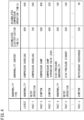
- FIG. 4 is a chart exemplifying content of abnormality information, retry information, and symptom information stored in a storage unit.
- the storage unit 72 stores an abnormality state (abnormality, retry operation, or a symptom), abnormality content, accumulated electrification time (also simply called “electrification time”) upon abnormality occurrence, and accumulated compressor operation time upon abnormality occurrence, which are associated with one another.
- the accumulated compressor operation time corresponds to operation time while the air conditioner 11 is actually conditioning air.
- FIG. 4 describes "abnormality", “symptoms", and "retry operation” are listed from the bottom in accordance with the order of occurrence.
- the storage unit 72 is configured to store latest information and information on past n events.
- the value n can be exemplarily 83, in which case the storage unit 72 can store information on 84 events in total.
- FIG. 6A to FIG. 6C are charts each exemplifying content of abnormality information, retry information, and symptom information displayed on a display unit of the outdoor control unit.
- the display unit 73 displays "abnormality information", "retry information”, and "symptom information” stored in the storage unit 72.
- the display unit 73 adopts digital display with seven segments or the like, and displays abnormality information, retry information, and symptom information in a coded manner with use of numbers, alphabets, and the like.
- the display unit 73 according to the present embodiment displays, as abnormality information, retry information, and symptom information, abnormality content, retry operation content, and symptom content, respectively, in the coded manner.
- the display unit 73 displays abnormality information, retry information, and symptom information on each of three events, namely, "latest", “past 1", and "past 2". Accordingly, a service person in charge of its recovery checks the display unit 73 when the air conditioner 11 stops due to abnormality, so as to find content of actually occurred abnormality as well as information on retry operation and a symptom recently occurred to utilize retry information and symptom information for determination of a cause of the occurred abnormality. However, the display unit 73 simply individually displays three pieces of each type of abnormality information, retry information, and symptom information. It is thus difficult to understand mutual relationships thereof.
- the outdoor control unit 70 according to the present embodiment is thus configured to output in a form enabling understanding of the mutual relationships of these pieces of information.
- the output unit 74 of the outdoor control unit 70 outputs abnormality information, retry information, and symptom information stored in the storage unit 72 to an external instrument exemplified by a terminal 100 (hereinafter, also referred to as "service terminal") such as a PC or a smartphone carried by the service person.
- the output unit 74 is provided on a control board or the like constituting the outdoor control unit 70, and is constituted by an output interface or the like wiredly connected with the service terminal 100.
- the output unit 74 may alternatively a communication device configured to wirelessly output abnormality information and the like.
- abnormality information, retry information, and symptom information stored in the storage unit 72 each include electrification time and operation time of the air conditioner 11 at a timepoint of occurrence thereof, and the output unit 74 externally outputs the abnormality information, the retry information, and the symptom information each including information on occurred time thereof. It is thus possible to chronologically check the abnormality information, the retry information, and the symptom information having been outputted as indicated in FIG. 4 or the like. The service person can accordingly find, on the basis of the information thus outputted, what kind of retry operation has been executed or what kind of a symptom has occurred before abnormality occurrence. The service person can thus easily estimate the cause of the occurred abnormality in accordance with the retry information and the symptom information, to appropriately and promptly execute recovery (repair or replacement of a component) from the abnormality.
- Abnormality information, retry information, and symptom information include electrification time and operation time of the air conditioner 11 as information on occurred time.
- the electrification time enables determination of whether or not a cause of occurred abnormality, retry operation, or a symptom is relevant to wearing or deterioration due to operation of the air conditioner 11.
- the electrification time enables determination of whether or not the cause of occurred abnormality, retry operation, or a symptom is relevant to a life span.
- the output unit 74 may alternatively be configured to output, to the display unit 73 of the outdoor control unit 70, abnormality information, retry information, and symptom information in a form enabling chronological checking of these pieces of information.
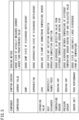
- FIG. 5 is a chart exemplifying content of abnormality information, retry information, and symptom information stored in the storage unit.
- FIG. 5 exemplifies components constituting the air conditioner 11, content of abnormality symptoms possibly occurring to the components, and methods of sensing the content, which are associated with one another. For example, “current value”, “damp”, and “superheating” exemplify content of abnormality symptoms possibly occurring to the compressor 30.
- the "current value” means sensing a state where a value of current flowing in the motor of the compressor 30 is larger than a predetermined value.
- the current value in this case adopts a moving average from current time to before a predetermined period, for sensing of long-term abnormality in current value.
- the "damp” means sensing a damp sate (having a degree of superheating less than a predetermined value) of the refrigerant discharged from the compressor 30.
- the “superheating” means sensing a superheating sate (having a degree of superheating equal to or more than the predetermined value) of the refrigerant discharged from the compressor 30.
- the outdoor control unit 70 diagnoses the compressor 30 as having an "abnormality symptom".
- the air conditioner 11 continuously operates because the air conditioner 11 does not have readily trouble in operation even upon sensing of any one of these states.
- FIG. 5 exemplifies "leak” as content of an abnormality symptom possibly occurring to the expansion valve 34.
- the refrigerant temperature sensor disposed downstream of the expansion valve 34 senses a refrigerant damp state.
- the outdoor control unit 70 diagnoses the expansion valve 34 as having an "abnormality symptom".
- FIG. 5 exemplifies "imperfectly thawed frost" as content of an abnormality symptom possibly occurring to the outdoor heat exchanger 33.
- the outdoor control unit 70 diagnoses the outdoor heat exchanger 33 as having an "abnormality symptom".
- the air conditioner 11 continuously operates because the air conditioner 11 does not have readily trouble in operation even upon sensing of any one of these states.
- FIG. 5 exemplifies a "sensing gap" as an abnormality symptom of any of the temperature sensors 53 to 59. This means sensing divergence in detection value between a temperature sensor as a diagnosis target and a different temperature sensor. Upon detection of this state, the outdoor control unit 70 diagnoses the temperature sensor as having an "abnormality symptom".
- FIG. 5 exemplifies a "sensing gap" as an abnormality symptom of the pressure sensor 51 or 52. This means sensing divergence between saturation temperature corresponding to pressure (calculated value) obtained from the detection value of the pressure sensor 51 or 52 as a diagnosis target, and the detection value of a different temperature sensor. Upon sensing of this state, the outdoor control unit 70 diagnoses the pressure sensor 51 or 52 as having an "abnormality symptom".
- the outdoor control unit 70 does not stop but continues operation of the air conditioner 11.
- the abnormality symptoms indicated in FIG. 5 the "current value" of the compressor 30, the “leak” of the expansion valve, the “imperfectly thawed frost” of the heat exchanger 33, the "sensing gap” of any of the temperature sensors 53 to 59, and the “sensing gap” of the pressure sensor 51 or 52 are sensed in accordance with a method different from the method of sensing abnormality occurrence, in order for detection of slight abnormality that does not need to stop the air conditioner 11.
- Each of the various sensors included in the air conditioner 11 may gradually have a "sensing gap" of having a detection value different from a normal value. If such a "sensing gap" increases, the air conditioner 11 may not be appropriately controlled and have trouble in operation.
- the air conditioner 11 according to the present embodiment will thus have diagnosis that there is an abnormality symptom if any of the temperature sensors 53 to 59 and the pressure sensors 51 and 52 has a "sensing gap".
- Diagnosis as having a "sensing gap" of any of the temperature sensors 53 to 59 and the pressure sensors 51 and 52 is executed while the air conditioner 11 stops operation.
- the outdoor control unit 70 compares the detection value of each of the temperature sensors 53 to 59 and the calculated value obtained from the detection value of each of the pressure sensors 51 and 52 with a predetermined reference value. If there is large divergence from the reference value continuously for at least predetermined time, the outdoor control unit 70 diagnoses the sensor as having a "sensing gap".
- the outdoor control unit 70 diagnoses as to a "sensing gap" by setting a value corresponding to outdoor air temperature as the "reference value”, and comparing the reference value with the detection values of the temperature sensors 53 to 59 and the saturation temperature corresponding to pressure (calculated value) obtained from the detection value of each of the pressure sensors 51 and 52.
- FIG. 7 is a flowchart depicting a procedure of diagnosing as a sensing gap of a temperature sensor.
- step S1 the outdoor control unit 70 determines whether or not the air conditioner 11 is stopped.
- the outdoor control unit 70 proceeds with processing to step S2 if determination in step S1 is positive (Yes).
- step S2 the outdoor control unit 70 acquires detection values of the temperature sensors 53 to 59. Subsequently in step S3, the outdoor control unit 70 calculates a reference value with use of the detection values of the plurality of temperature sensors 53 to 59.
- the present embodiment sets the reference value as a median of some of the detection values among the detection values of the plurality of temperature sensors 53 to 59.
- the median is adopted as the reference value because outdoor air temperature can be improved in reproducibility by decreasing possibility of being affected by any unusually high value or any low value included in the detection values of the plurality of temperature sensors.
- the reference value is obtained by preferably using three or more temperature sensors.
- the reference value can be set as an average of two values close to the median.
- the temperature sensors 54 and 59 according to the present embodiment are not used for calculation of the reference value because the temperature sensors 54 and 59 are disposed around the compressor 30 and are likely to be affected by heat of the compressor 30.
- step S4 the outdoor control unit 70 determines whether or not a difference between the detection value of each of the temperature sensors 53 to 58 and the reference value exceeds a predetermined threshold. If determination in step S4 is positive (Yes), the outdoor control unit 70 determines in step S5 whether or not predetermined time has elapsed after a stop of the air conditioner 11. Examples of the predetermined time include eight hours. If determination in step S5 is positive (Yes), the outdoor control unit 70 diagnoses a corresponding one of the temperature sensors 53 to 59 as having a "sensing gap", stores as abnormality symptom information in the storage unit 72, and ends processing.
- step S4 determines whether the determination in step S4 is negative (No) or not. If the determination in step S4 is negative (No), the outdoor control unit 70 proceeds with processing to step S8, diagnoses the temperature sensors 53 to 59 as having no "sensing gap", and ends processing.
- the predetermined threshold referred to in step S4 can be set in accordance with a type of the temperature sensor as a diagnosis target.
- the compressor 30 is heated by a crankcase heater while the air conditioner 11 is stopped.
- the temperature sensors 54 and 59 disposed around the compressor 30 are thus higher in detection value than the remaining temperature sensors 53 and 55 to 58. These temperature sensors 54 and 59 are accordingly provided with a highly set threshold.
- Time for diagnosis as a "sensing gap" is set to as long as eight hours because there needs certain time until detection values of temperature sensors converge to ambient temperature (outdoor air temperature). However, the time should not be particularly limited.
- FIG. 8 is a flowchart depicting a procedure of diagnosing as a sensing gap of a pressure sensor.
- step S11 the outdoor control unit 70 determines whether or not the air conditioner 11 is stopped.
- the outdoor control unit 70 proceeds with processing to step S12 if the determination in step S1 is positive (Yes).
- step S12 the outdoor control unit 70 acquires detection values of the pressure sensors 51 and 52 and the temperature sensors 53 to 59. Subsequently in step S13, the outdoor control unit 70 calculates a reference value with use of a plurality of detection values among the detection values of the plurality of temperature sensors 53 to 59.
- the present embodiment sets the reference value as a median of a plurality of detection values. The median is adopted as the reference value because outdoor air temperature can be improved in reproducibility by decreasing opportunity of being affected by any unusually high or low value included in the detection values of the plurality of temperature sensors.
- the reference value is obtained by preferably using three or more temperature sensors.
- the reference value can be set as an average of two values close to a center.
- the temperature sensors 54 and 59 are not used for calculation of the reference value because the temperature sensors 54 and 59 are disposed around the compressor 30 and are likely to be affected by heat of the compressor 30.
- step S14 the outdoor control unit 70 calculates saturation temperature corresponding to pressure of the refrigerant with use of the detection value of each of the pressure sensors 51 and 52.
- step S15 the outdoor control unit 70 determines whether or not a difference between the saturation temperature corresponding to pressure obtained from the detection value of each of the pressure sensors 51 and 52 and the reference value exceeds a predetermined threshold. If determination in step S15 is positive, the outdoor control unit 70 determines in step S16 whether or not predetermined time has elapsed after a stop of the air conditioner 11. Examples of the predetermined time include eight hours. If determination in step S16 is positive (Yes), the outdoor control unit 70 diagnoses the pressure sensor 51 or 52 as having a "sensing gap" (step S17), stores as abnormality symptom information in the storage unit 72 (step S18), and ends processing.
- step S15 If determination in step S15 is negative (No), the outdoor control unit 70 proceeds with processing to step S19, diagnoses the pressure sensor 51 or 52 as having no "sensing gap", and ends processing.
- the reference value calculated in each of step S3 in FIG. 7 and step S13 in FIG. 8 should not be limited to the median of the detection values of the plurality of temperature sensors, but may alternatively be an average.
- the average is more preferably calculated with use of the plurality of detection values excluding the maximum value and the minimum value.
- the detection values of each of the temperature sensors that are not diagnosis targets may be used for calculation of the reference value.
- the air conditioner 11 includes the temperature sensor 58 configured to detect outdoor air temperature, and the detection value of the temperature sensor 58 can alternatively be adopted as the reference value. If the temperature sensor 58 itself has a "sensing gap" in this case, it is impossible to detect a sensing gap of each of the remaining temperature sensors 53 to 57 and 59. It is thus more preferred to set the reference value with use of the median or the average of the detection values of the plurality of temperature sensors.
- the processing unit 71 in the outdoor control unit 70 may obtain a correction factor in accordance with a difference between the detection value of the temperature sensor or the calculated value (saturation temperature corresponding to pressure) obtained from the detection value of the pressure sensor and the reference value, and control operation of the air conditioner 11 with use of the correction factor.
- the processing unit 71 in the outdoor control unit 70 may transmit an abnormality diagnosis result to the centralized management device 50 that may manage abnormality information, retry information, and symptom information.
- the processing unit 71 in the outdoor control unit 70 may alternatively transmit the abnormality diagnosis result to the management server 62 that may manage the abnormality diagnosis result. Transmitting not operation data of the air conditioner 11 but only the abnormality diagnosis result achieves inhibition of increase in communication volume.
- the management server 62 manages the abnormality diagnosis result, in order to resolve inconvenience that the outdoor control unit 70 cannot refer to abnormality information, retry information, and symptom information, the management server 62 is more preferred to include a transmission unit configured to transmit abnormality information, retry information, and symptom information to the service terminal 100, the centralized management device 50, or the like via the wide area communication network 63.
- the air conditioner 11 includes the abnormality diagnostic system (the outdoor control unit 70).
- the centralized management device 50 may include the abnormality diagnostic system.
- operation data of the air conditioner 11 is transmitted from the air conditioner 11 to the centralized management device 50, and the control unit 50a in the centralized management device 50 executes abnormality diagnosis.
- operation data is transmitted from the air conditioner 11 to the centralized management device 50 only at predetermined time intervals and there is thus limitation in volume of the operation data that can be used for abnormality diagnosis. It is therefore more preferred to provide the abnormality diagnostic system in the air conditioner 11 in terms of more accurate abnormality diagnosis.
- the management server 62 may alternatively be provided with the abnormality diagnostic system.
- operation data of the air conditioner 11 is transmitted from the centralized management device 50 or the air conditioner 11 to the management server 62, and the control unit 62a in the management server 62 executes abnormality diagnosis.
- the abnormality diagnostic system is more preferably provided in the air conditioner 11 or the centralized management device 50.
- the management server 62 manages the abnormality diagnosis result, in order to resolve inconvenience that the outdoor control unit 70 and the centralized management device 50 cannot refer to abnormality information, retry information, and symptom information, the management server 62 is more preferred to include a transmission unit configured to transmit abnormality information, retry information, and symptom information to the service terminal 100, the centralized management device 50, or the like via the wide area communication network 63.
- the processing unit 71, the storage unit 72, and the output unit 74 constituting the abnormality diagnostic system are included in one device (the outdoor control unit 70 of the air conditioner 11, the control unit 50a of the centralized management device 50, or the control unit 62a of the management server 62). These units may alternatively be included in different instruments, such as different control units (computers), and these different control units may cooperate with each other to constitute the abnormality diagnostic system.
- the plurality of temperature sensors 53 to 59 and the plurality of pressure sensors 51 and 52 are diagnosis targets of a "sensing gap".
- at least one of these sensors has only to be the diagnosis target of the sensing gap.
Landscapes
- Engineering & Computer Science (AREA)
- Combustion & Propulsion (AREA)
- Mechanical Engineering (AREA)
- General Engineering & Computer Science (AREA)
- Chemical & Material Sciences (AREA)
- Health & Medical Sciences (AREA)
- Biomedical Technology (AREA)
- Signal Processing (AREA)
- Physics & Mathematics (AREA)
- Human Computer Interaction (AREA)
- Mathematical Physics (AREA)
- Fuzzy Systems (AREA)
- Air Conditioning Control Device (AREA)
Abstract
Description
- The present disclosure relates to an abnormality diagnostic system, an air conditioner, and an air conditioning system.
- As described in
PATENT LITERATURE 1 and the like, there has been conventionally known an air conditioner including a refrigerant circuit configured to execute vapor compression refrigeration cycle operation by driving a compressor, and the air conditioner is configured to cool or heat an indoor space. The air conditioner according toPATENT LITERATURE 1 detects with use of sensors or estimates in accordance with a graph or the like, operation data such as current and voltage of a compressor motor, evaporation temperature, condensation temperature, evaporation pressure, and condensation pressure of a refrigerant, estimates abnormality such as high or low pressure abnormality of the compressor, abnormality on a degree of suction superheating, poor lubrication, or liquid compression with use of a result of operation data, and enables execution of operation avoiding the abnormality. - PATENT LITERATURE 1:
Japanese Patent No. 4932636 - The air conditioner according to
PATENT LITERATURE 1 is not configured to specify a cause of any abnormality actually occurred to disable continuous operation. It is thus impossible to accurately find the cause of the abnormality even if a service person or the like checks a state of the air conditioner after the abnormality occurs, and it is difficult to promptly apply treatment. - It is an object of the present disclosure to provide an abnormality diagnostic system configured to accurately specify a cause of abnormality, an air conditioner, and an air conditioning system.
-
- (1) The present disclosure provides an abnormality diagnostic system including: a processing unit configured to acquire operation data of an air conditioner and determine occurrence of abnormality and occurrence of an abnormality symptom in the air conditioner; a storage unit configured to store abnormality information including content of the abnormality and information on occurred time of the abnormality, and symptom information including content of the symptom and information on occurred time of the symptom; and an output unit configured to output the abnormality information and the symptom information stored in the storage unit.
According to the abnormality diagnostic system thus configured, the storage unit stores the abnormality information including the information on the occurred time of the abnormality, and the symptom information including the information on the occurred time of the symptom, and the output unit outputs the abnormality information and the symptom information. It is thus possible to chronologically check occurrence of the abnormality and the symptom in accordance with the information thus outputted. It is thus possible to check an abnormality symptom occurred before any abnormality occurred to the air conditioner, and utilize the symptom information for abnormality cause specification. - (2) Preferably, the information on the occurred time corresponds to electrification time of the air conditioner.
According to the above configuration, the storage unit stores the content of the abnormality and the symptom as well as the electrification time of the air conditioner, to enable chronologically checking occurrence of the abnormality and the symptom and determining whether or not occurrence of the abnormality and the symptom have a cause due to a life span in accordance with the electrification time. - (3) Preferably, the information on the occurred time corresponds to operation time of the air conditioner.
According to the above configuration, the content of the abnormality and the symptom is stored along with the operation time of the air conditioner, to enable chronologically checking occurrence of the abnormality and the symptom and determining whether or not occurrence of the abnormality and the symptom have a cause due to wearing or deterioration by operation of the air conditioner in accordance with the electrification time. - (4) Preferably, the storage unit stores restart information including content of a restart of the air conditioner to be executed before definition of the abnormality, and information on occurred time of the restart, and the output unit outputs the abnormality information, the symptom information, and the restart information stored in the storage unit.
According to the above configuration, the symptom information as well as the restart information can be used for specification of an abnormality cause. - (5) Preferably, the processing unit causes a notification unit of the air conditioner to notify of the content of the abnormality upon occurrence, and causes the notification unit not to notify of the content of the symptom upon occurrence.
According to the above configuration, a use is not notified of occurrence of any abnormality symptom so as to prevent the user from executing an unnecessary action (stopping air conditioning or notifying a manager). - (6) The present disclosure provides an air conditioner including the abnormality diagnostic system according to any one of (1) to (5) described above.
The operation data acquired by the air conditioner itself thus configured can be directly applied to diagnosis of abnormality and a symptom, and information thereon can be kept in the air conditioner itself. When the air conditioner has any abnormality, it is thus possible to promptly specify a cause of the abnormality with use of the information on the symptom stored in the air conditioner. This also achieves reduction in communication volume because there is no need to transmit the information on the abnormality and the symptom externally (e.g. to a remote service center) for management of these pieces of information. - (7) The present disclosure provides an air conditioning system including: an air conditioner; and a management device connected with the air conditioner via a local communication network, in which the management device includes the abnormality diagnostic system according to any one of (1) to (5) described above.
The above configuration enables the management device connected to the air conditioner via the local communication network to diagnose as abnormality and a symptom and manage abnormality information and symptom information. In the air conditioner installed in a large facility such as a building, the management device can thus centralizedly control the abnormality information and the symptom information. This also achieves reduction in communication volume because there is no need to transmit the abnormality information and the symptom information externally (e.g. to a remote service center) for management of the abnormality information and the symptom information. - (8) The present disclosure provides an air conditioning system including: an air conditioner; a first management device connected to the air conditioner via a local communication network; and a second management device connected to the first management device via a wide area communication network, in which the air conditioner or the first management device includes the abnormality diagnostic system according to any one of (1) to (5) described above, and the abnormality diagnostic system includes a transmission unit configured to transmit the abnormality information and the symptom information to the second management device.
According to the above configuration, the abnormality information and the symptom information can be transmitted to the second management device connected via the wide area communication network, to enable management of the abnormality information and the symptom information on the air conditioner at a place distant from a site equipped with the air conditioner. Transmitted to the second management device is not the operation data for diagnosis of abnormality and a symptom, but the abnormality information and the symptom information as a diagnosis result, leading to reduction in volume of communication to the second management device. - (9) The present disclosure provides an air conditioning system including: an air conditioner; and a management device connected to the air conditioner via a wide area communication network, in which the management device includes the abnormality diagnostic system according to any one of (1) to (5) described above, and the abnormality diagnostic system includes a transmission unit configured to transmit the abnormality information or the symptom information via the wide area communication network.
-
-
FIG. 1 is a configuration diagram of an air conditioning system according to an embodiment of the present disclosure. -
FIG. 2 is a schematic refrigerant circuit diagram of an air conditioner. -
FIG. 3 is a configuration diagram of an outdoor control unit. -
FIG. 4 is a chart exemplifying content of abnormality information, retry information, and symptom information stored in a storage unit. -
FIG. 5 is a chart of exemplary abnormality symptom sensing. -
FIG. 6A is a chart exemplifying content of abnormality information displayed on a display unit. -
FIG. 6B is a chart exemplifying content of retry information displayed on the display unit. -
FIG. 6C is a chart exemplifying content of symptom information displayed on the display unit. -
FIG. 7 is a flowchart depicting a procedure of diagnosing as a sensing gap of a temperature sensor. -
FIG. 8 is a flowchart depicting a procedure of diagnosing as a sensing gap of a pressure sensor. - Embodiments of an air conditioning system will be described in detail hereinafter with reference to the accompanying drawings.
-
FIG. 1 is a configuration diagram of an air conditioning system according to an embodiment of the present disclosure. - As depicted in
FIG. 1 , the air conditioning system includes anair conditioner 11, acentralized management device 50, and amanagement server 62. Theair conditioner 11 adjusts, to predetermined target temperature, air temperature in an indoor space as an air conditioning target space. Theair conditioner 11 according to the present embodiment is configured to cool and heat the indoor space. - The
air conditioner 11 includes anindoor unit 21 and anoutdoor unit 22. Theair conditioner 11 is of a multiple type and exemplarily includes a plurality ofindoor units 21 connected parallelly to theoutdoor unit 22. Theair conditioner 11 may alternatively include a singleoutdoor unit 22 and a singleindoor unit 21. -
FIG. 2 is a schematic refrigerant circuit diagram of an air conditioner. - As depicted in
FIG. 2 , theair conditioner 11 includes arefrigerant circuit 23. Therefrigerant circuit 23 is configured to circulate a refrigerant between each of theindoor units 21 and theoutdoor unit 22. Therefrigerant circuit 23 includes acompressor 30, anoil separator 31, a four-way switching valve 32, an outdoor heat exchanger (heat source heat exchanger) 33, anoutdoor expansion valve 34, asubcooler 35, aliquid shutoff valve 36, anindoor expansion valve 24, an indoor heat exchanger (utilization heat exchanger) 25, agas shutoff valve 37, anaccumulator 38,refrigerant pipes - The
indoor unit 21 includes theindoor expansion valve 24 and the indoor heat exchanger 25 constituting therefrigerant circuit 23. Theindoor expansion valve 24 is constituted by a motor valve configured to adjust a refrigerant flow rate. The indoor heat exchanger 25 is of a cross-fin tube type or a microchannel type, and is used for heat exchange with indoor air. - The
indoor unit 21 further includes anindoor fan 26 and anindoor temperature sensor 27. Theindoor fan 26 is configured to bring indoor air into theindoor unit 21, cause heat exchange with the brought in air in the indoor heat exchanger 25, and cause the air to blow indoors. Theindoor fan 26 includes a motor having a number of operating revolutions adjustable in accordance with inverter control. Theindoor temperature sensor 27 detects indoor temperature. - The
outdoor unit 22 includes thecompressor 30, theoil separator 31, the four-way switching valve 32, the outdoor heat exchanger 33, theoutdoor expansion valve 34, thesubcooler 35, theliquid shutoff valve 36, thegas shutoff valve 37, and theaccumulator 38, which constitute therefrigerant circuit 23. - The
compressor 30 sucks a low-pressure gas refrigerant and discharges a highpressure gas refrigerant. Thecompressor 30 includes a motor having a number of operating revolutions adjustable in accordance with inverter control. Thecompressor 30 is of a variable capacity type (performance variable type) having capacity (performance) variable in accordance with inverter control of the motor. Thecompressor 30 may alternatively be of a constant capacity type. There may alternatively be provided a plurality ofcompressors 30. In this case, the compressors may include both thecompressor 30 of the variable capacity type and thecompressor 30 of the constant capacity type. - The
oil separator 31 is configured to separate refrigerating machine oil contained in a refrigerant discharged from thecompressor 30. The refrigerating machine oil separated in theoil separator 31 is returned to thecompressor 30 via anoil return tube 41. Theoil return tube 41 is provided with an on-offvalve 42. The on-offvalve 42 is configured as an electromagnetic valve. When the on-offvalve 42 is opened, the refrigerating machine oil in theoil separator 31 passes theoil return tube 41 and is sucked into thecompressor 30 along with the refrigerant flowing in asuction pipe 44. - The four-
way switching valve 32 reverses a refrigerant flow in the refrigerant pipe, and switchingly supplies one of the outdoor heat exchanger 33 and the indoor heat exchanger 25 with the refrigerant discharged from thecompressor 30. Theair conditioner 11 can thus switchingly execute cooling operation and heating operation. - The outdoor heat exchanger 33 is of a cross-fin tube type, a microchannel type, or the like, and causes heat exchange with the refrigerant with use of air as a heat source to condense or evaporate the refrigerant.
- The
outdoor expansion valve 34 is constituted by a motor valve configured to adjust a refrigerant flow rate or the like. - The
subcooler 35 subcools a refrigerant condensed in the outdoor heat exchanger 33. Thesubcooler 35 includes a firstheat transfer tube 35a and a secondheat transfer tube 35b. The firstheat transfer tube 35a has a first end connected to a refrigerant pipe extending to theoutdoor expansion valve 34. The firstheat transfer tube 35a has a second end connected to a refrigerant pipe extending to theliquid shutoff valve 36. The secondheat transfer tube 35b has a first end connected to a branchingtube 35c branching from a refrigerant pipe disposed between the firstheat transfer tube 35a and theoutdoor expansion valve 34. The branchingtube 35c is provided with anexpansion valve 43. The secondheat transfer tube 35b has a second end connected to thesuction pipe 44 provided to return the refrigerant to thecompressor 30. - The
subcooler 35 causes heat exchange between the refrigerant flowing from thecompressor 30, passing the outdoor heat exchanger 33 and theexpansion valve 34, and flowing in the firstheat transfer tube 35a, and the refrigerant decompressed by theexpansion valve 43 and flowing in the secondheat transfer tube 35b, and subcools the refrigerant flowing in the firstheat transfer tube 35a. The refrigerant flowing in the secondheat transfer tube 35b passes thesuction pipe 44, and is sucked into thecompressor 30 via theaccumulator 38. - The
accumulator 38 temporarily reserves a low-pressure refrigerant to be sucked into thecompressor 30, for separation between a gas refrigerant and a liquid refrigerant. Theaccumulator 38 is provided on thesuction pipe 44. Theaccumulator 38 is connected with a first end of anoil return tube 45. Theoil return tube 45 has a second end connected to thesuction pipe 44. Theoil return tube 45 is provided to return the refrigerating machine oil from theaccumulator 38 to thecompressor 30. Theoil return tube 45 is provided with an on-offvalve 46. The on-offvalve 46 is configured as an electromagnetic valve. When the on-offvalve 46 is opened, the refrigerating machine oil in theaccumulator 38 passes theoil return tube 45 and is sucked into thecompressor 30 along with the refrigerant flowing in thesuction pipe 44. - The
liquid shutoff valve 36 is a manually operated on-off valve. Thegas shutoff valve 37 is also a manually operated on-off valve. Theliquid shutoff valve 36 and thegas shutoff valve 37 are closed to block refrigerant flows in therefrigerant pipes refrigerant pipes - The
outdoor unit 22 further includes anoutdoor fan 39,pressure sensors temperature sensors 53 to 59, acurrent sensor 60, and the like. Theoutdoor fan 39 includes a motor having a number of operating revolutions adjustable in accordance with inverter control. Theoutdoor fan 39 is configured to bring outdoor air into theoutdoor unit 22, cause heat exchange with the brought in air in the outdoor heat exchanger 33, and cause the air to blow out of theoutdoor unit 22. - The
pressure sensors suction pressure sensor 51 and adischarge pressure sensor 52. Thesuction pressure sensor 51 detects pressure of a refrigerant sucked into thecompressor 30. Thedischarge pressure sensor 52 detects pressure of a refrigerant discharged from thecompressor 30. - The
temperature sensors 53 to 59 includerefrigerant temperature sensors 53 to 57 configured to detect refrigerant temperature, an outdoorair temperature sensor 58 configured to detect outdoor air temperature, and atemperature sensor 59 configured to detect surface temperature of thecompressor 30. Therefrigerant temperature sensor 53 detects temperature of a refrigerant sucked into thecompressor 30. Therefrigerant temperature sensor 54 detects temperature of a refrigerant discharged from thecompressor 30. The refrigerant temperature sensor 55 detects temperature of a refrigerant on a liquid side of the outdoor heat exchanger 33. Therefrigerant temperature sensor 56 detects temperature of a refrigerant provided between the subcooler 35 and theliquid shutoff valve 36. Therefrigerant temperature sensor 57 detects temperature of a refrigerant flowing out of the secondheat transfer tube 35b of thesubcooler 35. - Detection values of the
suction pressure sensor 51, thedischarge pressure sensor 52, and therefrigerant temperature sensors compressor 30, opening degrees of theoutdoor expansion valve 34 and theindoor expansion valve 24, and the like are controlled to adjust these values. - When the
air conditioner 11 thus configured executes cooling operation, the four-way switching valve 32 is kept in a state indicated by solid lines inFIG. 1 . Thecompressor 30 discharges a gas refrigerant having high temperature and high pressure, which flows into the outdoor heat exchanger 33 via the four-way switching valve 32, and exchanges heat with outdoor air due to functioning of theoutdoor fan 39 to be condensed and liquefied. The refrigerant thus liquefied passes theoutdoor expansion valve 34 in a fully opened state and thesubcooler 35, and flows into theindoor unit 21. The refrigerant in theindoor unit 21 is decompressed to have predetermined low pressure at theindoor expansion valve 24, and further exchanges heat with indoor air in the indoor heat exchanger 25 to be evaporated. Theindoor fan 26 causes the indoor air cooled due to evaporation of the refrigerant to blow indoors so as to cool the indoor space. The refrigerant evaporated in the indoor heat exchanger 25 returns to theoutdoor unit 22 via thegas refrigerant pipe 40G, and is sucked into thecompressor 30 by way of the four-way switching valve 32. Also during defrosting operation of removing frost adhering to the outdoor heat exchanger 33, theair conditioner 11 behaves similarly to behavior during cooling operation. - When the
air conditioner 11 executes heating operation, the four-way switching valve 32 is kept in a state indicated by broken lines inFIG. 1 . Thecompressor 30 discharges the gas refrigerant having high temperature and high pressure, which flows into the indoor heat exchanger 25 of theindoor unit 21 via the four-way switching valve 32. In the indoor heat exchanger 25, the refrigerant exchanges heat with indoor air to be condensed and liquefied. Theindoor fan 26 causes the indoor air heated due to condensation of the refrigerant to blow indoors so as to heat the indoor space. The refrigerant liquefied in the indoor heat exchanger 25 returns to theoutdoor unit 22 via the liquidrefrigerant pipe 40L, is decompressed to have predetermined low pressure at theoutdoor expansion valve 34, and further exchanges heat with outdoor air in the outdoor heat exchanger 33 to be evaporated. The refrigerant evaporated and gasified in the outdoor heat exchanger 33 passes the four-way switching valve 32 to be sucked into thecompressor 30. - The
indoor unit 21 further includes anindoor control unit 29 and aremote controller 29A. Theindoor control unit 29 is constituted by a microcomputer including a calculation unit such as a CPU and a storage unit such as a RAM or a ROM. Theindoor control unit 29 may include an integrated circuit such as an FPGA or an ASIC. Theindoor unit 21 includes sensors having detection values to be transmitted to theindoor control unit 29. Theindoor control unit 29 controls behavior of theindoor expansion valve 24 and theindoor fan 26 in accordance with the detection values of theindoor temperature sensor 27 and the like. - The
remote controller 29A is used to input commands to start and stop operation for theair conditioner 11, input operating modes such as cooling operation and heating operation, input indoor set temperature, and the like. Theremote controller 29A includes a display unit 29A1 (seeFIG. 3 ) configured to display setting content and the like. The display unit 29A1 functions also as a notification unit configured to notify a user of abnormality occurrence, as to be described later. - The
outdoor unit 22 further includes anoutdoor control unit 70. Theoutdoor control unit 70 is constituted by a microcomputer including a calculation unit such as a CPU and a storage unit such as a RAM or a ROM. Theoutdoor control unit 70 may include an integrated circuit such as an FPGA or an ASIC. Theoutdoor unit 22 includes thevarious sensors 51 to 60 having detection values to be transmitted to theoutdoor control unit 70. Theoutdoor control unit 70 controls behavior of thecompressor 30, theoutdoor fan 39, theexpansion valves various sensors 51 to 60. As to be described later, theoutdoor control unit 70 constitutes an abnormality diagnostic system configured to diagnose whether or not theair conditioner 11 has abnormality. - The
indoor control unit 29, theoutdoor control unit 70, and thecentralized management device 50 are connected via a local communication network such as a local area network (LAN). Specifically, theindoor control unit 29 and theoutdoor control unit 70 are mutually communicably connected via a transmission line. Theindoor control unit 29 and theoutdoor control unit 70 are mutually communicably connected to thecentralized management device 50 via transmission lines. - The
centralized management device 50 includes acontrol unit 50a like a microcomputer including a calculation unit such as a CPU and a storage unit such as a ROM or a RAM. Thecontrol unit 50a may include an integrated circuit such as an FPGA or an ASIC. Thecentralized management device 50 is installed in a control center of a building or the like. Thecentralized management device 50 manages theoutdoor unit 22 and theindoor unit 21. Specifically, thecentralized management device 50 causes thecontrol unit 50a to monitor working situations of theoutdoor unit 22 and theindoor unit 21, set air conditioning temperature, control to operate and stop, and the like. - The
management server 62 is provided at a remote location from the building equipped with theair conditioner 11. Themanagement server 62 is exemplarily constituted by a personal computer including acontrol unit 62a having a calculation unit such as a CPU and a storage unit such as a ROM or a RAM. Thecontrol unit 62a may include an integrated circuit such as an FPGA or an ASIC. Thecentralized management device 50 and themanagement server 62 are communicably connected via a widearea communication network 63 such as the Internet. - The air conditioning system according to the present embodiment may alternatively exclude the
centralized management device 50 and themanagement server 62. - The
outdoor control unit 70 constitutes the abnormality diagnostic system configured to sense occurrence of "abnormality", sense occurrence of an "abnormality symptom" (hereinafter, also simply called a "symptom") in theair conditioner 11. Theoutdoor control unit 70 acquires, as operation data, the detection values of thevarious sensors 51 to 60, control data of thecompressor 30, theoutdoor fan 39, theexpansion valves outdoor control unit 70 controls behavior of various instruments such as thecompressor 30, and senses abnormality and symptoms of theair conditioner 11. - Examples of the instruments as targets of sensing occurrence of abnormality and symptoms include the
compressor 30, theoutdoor fan 39, theexpansion valves temperature sensors 53 to 59, and thepressure sensors outdoor control unit 70 stops theair conditioner 11 upon sensing of occurrence of "abnormality" of theair conditioner 11. Theoutdoor control unit 70 continuously operates theair conditioner 11 upon sensing of occurrence of an "abnormality symptom" of theair conditioner 11. - The
outdoor control unit 70 executes retry operation of temporarily stopping theair conditioner 11 when predetermined abnormality occurs and operating again (restarting) after elapse of predetermined time. If abnormality occurs even when retry operation is executed a predetermined number of times, theoutdoor control unit 70 defines the abnormality as formal "abnormality". - A conventional and publicly known method can be applied to abnormality sensing. For example, the
compressor 30 can be determined as abnormal when current flowing in the motor has a value larger than a predetermined threshold, when thesuction pressure sensor 51 and thedischarge pressure sensor 52 have detection values larger or smaller than a predetermined threshold, when the detection values of thepressure sensors - A method described in
FIG. 5 or the like can be applied to sensing of an abnormality symptom. Details ofFIG. 5 will be described later. -
FIG. 3 is a configuration diagram of an outdoor control unit. - The
outdoor control unit 70 includes aprocessing unit 71, astorage unit 72, adisplay unit 73, and anoutput unit 74. Theprocessing unit 71 is constituted by a calculation device such as a CPU, and processes behavior control of thecompressor 30 as described above as well as abnormality diagnosis. - Upon sensing occurrence of "abnormality", "retry operation", and an "abnormality symptom", the
processing unit 71 processes to store, in thestorage unit 72, information thereon, namely, "abnormality information", "retry information (restart information)", and "symptom information". Theprocessing unit 71 processes to cause thedisplay unit 73 to display the "abnormality information", the "retry information", and the "symptom information" stored in thestorage unit 72. Theprocessing unit 71 further processes to cause the display unit 29A1 of theremote controller 29A to display the "abnormality information" among the types of information stored in thestorage unit 72. Note that theprocessing unit 71 processes to cause the display unit 29A1 to display not the "symptom information" or the "retry information" but only the "abnormality information". - The
storage unit 72 stores detection data of the various sensors in theair conditioner 11, and control data of thecompressor 30 and the like. When theprocessing unit 71 senses occurrence of "abnormality", "retry operation", and a "symptom", thestorage unit 72 stores "abnormality information", "retry information", and "symptom information" thereof. - The "abnormality information" includes abnormality content and information on occurred time thereof. The "symptom information" includes symptom content and information on occurred time thereof. The "retry information" includes abnormality content as a cause of retry operation, and information on occurred time thereof.
-
FIG. 4 is a chart exemplifying content of abnormality information, retry information, and symptom information stored in a storage unit. - As depicted in
FIG. 4 , thestorage unit 72 stores an abnormality state (abnormality, retry operation, or a symptom), abnormality content, accumulated electrification time (also simply called "electrification time") upon abnormality occurrence, and accumulated compressor operation time upon abnormality occurrence, which are associated with one another. The accumulated compressor operation time corresponds to operation time while theair conditioner 11 is actually conditioning air.FIG. 4 describes "abnormality", "symptoms", and "retry operation" are listed from the bottom in accordance with the order of occurrence. Thestorage unit 72 is configured to store latest information and information on past n events. The value n can be exemplarily 83, in which case thestorage unit 72 can store information on 84 events in total. -
FIG. 6A to FIG. 6C are charts each exemplifying content of abnormality information, retry information, and symptom information displayed on a display unit of the outdoor control unit. - The
display unit 73 displays "abnormality information", "retry information", and "symptom information" stored in thestorage unit 72. Thedisplay unit 73 adopts digital display with seven segments or the like, and displays abnormality information, retry information, and symptom information in a coded manner with use of numbers, alphabets, and the like. Thedisplay unit 73 according to the present embodiment displays, as abnormality information, retry information, and symptom information, abnormality content, retry operation content, and symptom content, respectively, in the coded manner. - The
display unit 73 displays abnormality information, retry information, and symptom information on each of three events, namely, "latest", "past 1", and "past 2". Accordingly, a service person in charge of its recovery checks thedisplay unit 73 when theair conditioner 11 stops due to abnormality, so as to find content of actually occurred abnormality as well as information on retry operation and a symptom recently occurred to utilize retry information and symptom information for determination of a cause of the occurred abnormality. However, thedisplay unit 73 simply individually displays three pieces of each type of abnormality information, retry information, and symptom information. It is thus difficult to understand mutual relationships thereof. Theoutdoor control unit 70 according to the present embodiment is thus configured to output in a form enabling understanding of the mutual relationships of these pieces of information. - As depicted in
FIG. 3 , theoutput unit 74 of theoutdoor control unit 70 outputs abnormality information, retry information, and symptom information stored in thestorage unit 72 to an external instrument exemplified by a terminal 100 (hereinafter, also referred to as "service terminal") such as a PC or a smartphone carried by the service person. Theoutput unit 74 is provided on a control board or the like constituting theoutdoor control unit 70, and is constituted by an output interface or the like wiredly connected with theservice terminal 100. Theoutput unit 74 may alternatively a communication device configured to wirelessly output abnormality information and the like. - As described earlier, abnormality information, retry information, and symptom information stored in the
storage unit 72 each include electrification time and operation time of theair conditioner 11 at a timepoint of occurrence thereof, and theoutput unit 74 externally outputs the abnormality information, the retry information, and the symptom information each including information on occurred time thereof. It is thus possible to chronologically check the abnormality information, the retry information, and the symptom information having been outputted as indicated inFIG. 4 or the like. The service person can accordingly find, on the basis of the information thus outputted, what kind of retry operation has been executed or what kind of a symptom has occurred before abnormality occurrence. The service person can thus easily estimate the cause of the occurred abnormality in accordance with the retry information and the symptom information, to appropriately and promptly execute recovery (repair or replacement of a component) from the abnormality. - Abnormality information, retry information, and symptom information include electrification time and operation time of the
air conditioner 11 as information on occurred time. The electrification time enables determination of whether or not a cause of occurred abnormality, retry operation, or a symptom is relevant to wearing or deterioration due to operation of theair conditioner 11. Similarly, the electrification time enables determination of whether or not the cause of occurred abnormality, retry operation, or a symptom is relevant to a life span. Theoutput unit 74 may alternatively be configured to output, to thedisplay unit 73 of theoutdoor control unit 70, abnormality information, retry information, and symptom information in a form enabling chronological checking of these pieces of information. -
FIG. 5 is a chart exemplifying content of abnormality information, retry information, and symptom information stored in the storage unit. -
FIG. 5 exemplifies components constituting theair conditioner 11, content of abnormality symptoms possibly occurring to the components, and methods of sensing the content, which are associated with one another. For example, "current value", "damp", and "superheating" exemplify content of abnormality symptoms possibly occurring to thecompressor 30. - The "current value" means sensing a state where a value of current flowing in the motor of the
compressor 30 is larger than a predetermined value. The current value in this case adopts a moving average from current time to before a predetermined period, for sensing of long-term abnormality in current value. The "damp" means sensing a damp sate (having a degree of superheating less than a predetermined value) of the refrigerant discharged from thecompressor 30. The "superheating" means sensing a superheating sate (having a degree of superheating equal to or more than the predetermined value) of the refrigerant discharged from thecompressor 30. Upon sensing any one of these states, theoutdoor control unit 70 diagnoses thecompressor 30 as having an "abnormality symptom". However, theair conditioner 11 continuously operates because theair conditioner 11 does not have readily trouble in operation even upon sensing of any one of these states. -
FIG. 5 exemplifies "leak" as content of an abnormality symptom possibly occurring to theexpansion valve 34. This means that the refrigerant temperature sensor disposed downstream of theexpansion valve 34 senses a refrigerant damp state. Upon sensing of this state, theoutdoor control unit 70 diagnoses theexpansion valve 34 as having an "abnormality symptom". -
FIG. 5 exemplifies "imperfectly thawed frost" as content of an abnormality symptom possibly occurring to the outdoor heat exchanger 33. This means that theair conditioner 11 executing defrosting operation does not satisfy a predetermined completion condition a number of times exceeding a predetermined number. Upon sensing of this state, theoutdoor control unit 70 diagnoses the outdoor heat exchanger 33 as having an "abnormality symptom". However, theair conditioner 11 continuously operates because theair conditioner 11 does not have readily trouble in operation even upon sensing of any one of these states. -
FIG. 5 exemplifies a "sensing gap" as an abnormality symptom of any of thetemperature sensors 53 to 59. This means sensing divergence in detection value between a temperature sensor as a diagnosis target and a different temperature sensor. Upon detection of this state, theoutdoor control unit 70 diagnoses the temperature sensor as having an "abnormality symptom". -
FIG. 5 exemplifies a "sensing gap" as an abnormality symptom of thepressure sensor pressure sensor outdoor control unit 70 diagnoses thepressure sensor - Operation of the
air conditioner 11 does not readily have trouble even upon such sensing of symptom occurrence. Accordingly, theoutdoor control unit 70 does not stop but continues operation of theair conditioner 11. Among the abnormality symptoms indicated inFIG. 5 , the "current value" of thecompressor 30, the "leak" of the expansion valve, the "imperfectly thawed frost" of the heat exchanger 33, the "sensing gap" of any of thetemperature sensors 53 to 59, and the "sensing gap" of thepressure sensor air conditioner 11. - Among the "abnormality symptoms" described above, the "sensing gap" of any of the
temperature sensors 53 to 59 and thepressure sensors - Each of the various sensors included in the
air conditioner 11 may gradually have a "sensing gap" of having a detection value different from a normal value. If such a "sensing gap" increases, theair conditioner 11 may not be appropriately controlled and have trouble in operation. Theair conditioner 11 according to the present embodiment will thus have diagnosis that there is an abnormality symptom if any of thetemperature sensors 53 to 59 and thepressure sensors - Diagnosis as having a "sensing gap" of any of the
temperature sensors 53 to 59 and thepressure sensors air conditioner 11 stops operation. Theoutdoor control unit 70 compares the detection value of each of thetemperature sensors 53 to 59 and the calculated value obtained from the detection value of each of thepressure sensors outdoor control unit 70 diagnoses the sensor as having a "sensing gap". - While the
air conditioner 11 is stopped, the detection values of thetemperature sensors 53 to 59 included in theair conditioner 11 will gradually converge to outdoor air temperature. The saturation temperature corresponding to pressure obtained from the detection value of each of thepressure sensors air conditioner 11 will converge to outdoor air temperature. According to the present embodiment, theoutdoor control unit 70 diagnoses as to a "sensing gap" by setting a value corresponding to outdoor air temperature as the "reference value", and comparing the reference value with the detection values of thetemperature sensors 53 to 59 and the saturation temperature corresponding to pressure (calculated value) obtained from the detection value of each of thepressure sensors -
FIG. 7 is a flowchart depicting a procedure of diagnosing as a sensing gap of a temperature sensor. - Description is made hereinafter to a procedure of diagnosing any of the
temperature sensors 53 to 59 as having a "sensing gap" with reference to the flowchart. - In step S1, the
outdoor control unit 70 determines whether or not theair conditioner 11 is stopped. Theoutdoor control unit 70 proceeds with processing to step S2 if determination in step S1 is positive (Yes). - In step S2, the
outdoor control unit 70 acquires detection values of thetemperature sensors 53 to 59. Subsequently in step S3, theoutdoor control unit 70 calculates a reference value with use of the detection values of the plurality oftemperature sensors 53 to 59. The present embodiment sets the reference value as a median of some of the detection values among the detection values of the plurality oftemperature sensors 53 to 59. The median is adopted as the reference value because outdoor air temperature can be improved in reproducibility by decreasing possibility of being affected by any unusually high value or any low value included in the detection values of the plurality of temperature sensors. - The reference value is obtained by preferably using three or more temperature sensors. When the reference value is obtained by using an even number of temperature sensors, the reference value can be set as an average of two values close to the median. The
temperature sensors temperature sensors compressor 30 and are likely to be affected by heat of thecompressor 30. - In step S4, the
outdoor control unit 70 determines whether or not a difference between the detection value of each of thetemperature sensors 53 to 58 and the reference value exceeds a predetermined threshold. If determination in step S4 is positive (Yes), theoutdoor control unit 70 determines in step S5 whether or not predetermined time has elapsed after a stop of theair conditioner 11. Examples of the predetermined time include eight hours. If determination in step S5 is positive (Yes), theoutdoor control unit 70 diagnoses a corresponding one of thetemperature sensors 53 to 59 as having a "sensing gap", stores as abnormality symptom information in thestorage unit 72, and ends processing. - If the determination in step S4 is negative (No), the
outdoor control unit 70 proceeds with processing to step S8, diagnoses thetemperature sensors 53 to 59 as having no "sensing gap", and ends processing. - The predetermined threshold referred to in step S4 can be set in accordance with a type of the temperature sensor as a diagnosis target. For example, the
compressor 30 is heated by a crankcase heater while theair conditioner 11 is stopped. Thetemperature sensors compressor 30 are thus higher in detection value than the remainingtemperature sensors 53 and 55 to 58. Thesetemperature sensors - Time for diagnosis as a "sensing gap" is set to as long as eight hours because there needs certain time until detection values of temperature sensors converge to ambient temperature (outdoor air temperature). However, the time should not be particularly limited.
-
FIG. 8 is a flowchart depicting a procedure of diagnosing as a sensing gap of a pressure sensor. - Description is made hereinafter to a procedure of diagnosing the
pressure sensor - In step S11, the
outdoor control unit 70 determines whether or not theair conditioner 11 is stopped. Theoutdoor control unit 70 proceeds with processing to step S12 if the determination in step S1 is positive (Yes). - In step S12, the
outdoor control unit 70 acquires detection values of thepressure sensors temperature sensors 53 to 59. Subsequently in step S13, theoutdoor control unit 70 calculates a reference value with use of a plurality of detection values among the detection values of the plurality oftemperature sensors 53 to 59. The present embodiment sets the reference value as a median of a plurality of detection values. The median is adopted as the reference value because outdoor air temperature can be improved in reproducibility by decreasing opportunity of being affected by any unusually high or low value included in the detection values of the plurality of temperature sensors. - The reference value is obtained by preferably using three or more temperature sensors. When the reference value is obtained by using an even number of temperature sensors, the reference value can be set as an average of two values close to a center. Preferably, the
temperature sensors temperature sensors compressor 30 and are likely to be affected by heat of thecompressor 30. - In step S14, the
outdoor control unit 70 calculates saturation temperature corresponding to pressure of the refrigerant with use of the detection value of each of thepressure sensors outdoor control unit 70 determines whether or not a difference between the saturation temperature corresponding to pressure obtained from the detection value of each of thepressure sensors outdoor control unit 70 determines in step S16 whether or not predetermined time has elapsed after a stop of theair conditioner 11. Examples of the predetermined time include eight hours. If determination in step S16 is positive (Yes), theoutdoor control unit 70 diagnoses thepressure sensor - If determination in step S15 is negative (No), the
outdoor control unit 70 proceeds with processing to step S19, diagnoses thepressure sensor - According to the present embodiment, the reference value calculated in each of step S3 in
FIG. 7 and step S13 inFIG. 8 should not be limited to the median of the detection values of the plurality of temperature sensors, but may alternatively be an average. In this case, the average is more preferably calculated with use of the plurality of detection values excluding the maximum value and the minimum value. - In the flowchart in each of
FIG. 7 andFIG. 8 , the detection values of each of the temperature sensors that are not diagnosis targets may be used for calculation of the reference value. Theair conditioner 11 includes thetemperature sensor 58 configured to detect outdoor air temperature, and the detection value of thetemperature sensor 58 can alternatively be adopted as the reference value. If thetemperature sensor 58 itself has a "sensing gap" in this case, it is impossible to detect a sensing gap of each of the remainingtemperature sensors 53 to 57 and 59. It is thus more preferred to set the reference value with use of the median or the average of the detection values of the plurality of temperature sensors. - When any of the
temperature sensors 53 to 59 and thepressure sensors processing unit 71 in theoutdoor control unit 70 may obtain a correction factor in accordance with a difference between the detection value of the temperature sensor or the calculated value (saturation temperature corresponding to pressure) obtained from the detection value of the pressure sensor and the reference value, and control operation of theair conditioner 11 with use of the correction factor. - The
processing unit 71 in theoutdoor control unit 70 may transmit an abnormality diagnosis result to thecentralized management device 50 that may manage abnormality information, retry information, and symptom information. Theprocessing unit 71 in theoutdoor control unit 70 may alternatively transmit the abnormality diagnosis result to themanagement server 62 that may manage the abnormality diagnosis result. Transmitting not operation data of theair conditioner 11 but only the abnormality diagnosis result achieves inhibition of increase in communication volume. In the case where themanagement server 62 manages the abnormality diagnosis result, in order to resolve inconvenience that theoutdoor control unit 70 cannot refer to abnormality information, retry information, and symptom information, themanagement server 62 is more preferred to include a transmission unit configured to transmit abnormality information, retry information, and symptom information to theservice terminal 100, thecentralized management device 50, or the like via the widearea communication network 63. - The
air conditioner 11 according to the above embodiment includes the abnormality diagnostic system (the outdoor control unit 70). Alternatively, thecentralized management device 50 may include the abnormality diagnostic system. In this case, operation data of theair conditioner 11 is transmitted from theair conditioner 11 to thecentralized management device 50, and thecontrol unit 50a in thecentralized management device 50 executes abnormality diagnosis. However, operation data is transmitted from theair conditioner 11 to thecentralized management device 50 only at predetermined time intervals and there is thus limitation in volume of the operation data that can be used for abnormality diagnosis. It is therefore more preferred to provide the abnormality diagnostic system in theair conditioner 11 in terms of more accurate abnormality diagnosis. - Similarly, the
management server 62 may alternatively be provided with the abnormality diagnostic system. In this case, operation data of theair conditioner 11 is transmitted from thecentralized management device 50 or theair conditioner 11 to themanagement server 62, and thecontrol unit 62a in themanagement server 62 executes abnormality diagnosis. This needs transmission of large volume of operation data of theair conditioner 11 to themanagement server 62 via the widearea communication network 63, leading to excessive increase in communication cost. Accordingly, the abnormality diagnostic system is more preferably provided in theair conditioner 11 or thecentralized management device 50. - In the case where the
management server 62 manages the abnormality diagnosis result, in order to resolve inconvenience that theoutdoor control unit 70 and thecentralized management device 50 cannot refer to abnormality information, retry information, and symptom information, themanagement server 62 is more preferred to include a transmission unit configured to transmit abnormality information, retry information, and symptom information to theservice terminal 100, thecentralized management device 50, or the like via the widearea communication network 63. - According to the above embodiment, the
processing unit 71, thestorage unit 72, and theoutput unit 74 constituting the abnormality diagnostic system are included in one device (theoutdoor control unit 70 of theair conditioner 11, thecontrol unit 50a of thecentralized management device 50, or thecontrol unit 62a of the management server 62). These units may alternatively be included in different instruments, such as different control units (computers), and these different control units may cooperate with each other to constitute the abnormality diagnostic system. - According to the above embodiment, the plurality of
temperature sensors 53 to 59 and the plurality ofpressure sensors -
- (1) The above embodiment provides the abnormality diagnostic system including: the processing
unit 71 configured to acquire operation data of theair conditioner 11 and determine occurrence of abnormality and occurrence of an abnormality symptom in theair conditioner 11; thestorage unit 72 configured to store abnormality information including content of the abnormality and information on occurred time of the abnormality, and symptom information including content of the symptom and information on occurred time of the symptom; and theoutput unit 74 configured to output the abnormality information and the symptom information stored in thestorage unit 72. In this manner, the storage unit stores the abnormality information including the information on the occurred time of the abnormality, and the symptom information including the information on the occurred time of the symptom, and the output unit outputs the abnormality information and the symptom information. It is thus possible to chronologically check occurrence of the abnormality and the symptom in accordance with the information thus outputted. It is accordingly possible to check an abnormality symptom occurred before any abnormality occurred to theair conditioner 11, and utilize the symptom information for abnormality cause specification. - (2) The
storage unit 72 according to the above embodiment stores the electrification time of theair conditioner 11. In other words, the information on the occurred time in the abnormality information and the symptom information corresponds to the electrification time of theair conditioner 11. In this manner, thestorage unit 72 stores the content of the abnormality and the content of the symptom as well as the electrification time of theair conditioner 11, to enable chronologically checking occurrence of the abnormality and the symptom and determining whether or not occurrence of the abnormality and the symptom have a cause due to a life span in accordance with the electrification time. - (3) The
storage unit 72 according to the above embodiment stores the operation time of thecompressor 30 in theair conditioner 11. In other words, the information on the occurred time in the abnormality information and the symptom information can correspond to the operation time of theair conditioner 11. In this manner, the content of the abnormality and the symptom is stored along with the operation time of theair conditioner 11, to enable chronologically checking occurrence of the abnormality and the symptom and determining whether or not occurrence of the abnormality and the symptom have a cause due to wearing or deterioration by operation of theair conditioner 11 in accordance with the electrification time. - (4) According to the above embodiment, the
storage unit 72 stores the restart information (retry information) including the content of a restart and the information on the occurred time of the restart of theair conditioner 11 to be executed before definition of the abnormality, and theoutput unit 74 outputs the abnormality information, the symptom information, and the retry information stored in thestorage unit 72. Accordingly, the symptom information as well as the retry information can be used for specification of an abnormality cause. - (5) According to the above embodiment, the processing unit (71) causes the notification unit of the air conditioner (11) to notify of the content of the abnormality upon occurrence, and causes the notification unit not to notify of the content of the symptom upon occurrence. Accordingly, a use is not notified of occurrence of any abnormality symptom so as to prevent the user from executing an unnecessary action (stopping air conditioning or notifying a manager).
- (6) The abnormality diagnostic system according to the above embodiment is provided in the
air conditioner 11. The operation data acquired by theair conditioner 11 itself can thus be directly applied to diagnosis of abnormality and a symptom, and information thereon can be kept in theair conditioner 11 itself. When theair conditioner 11 has any abnormality, it is thus possible to promptly specify a cause of the abnormality with use of the symptom information stored in theair conditioner 11. This also achieves reduction in communication volume because there is no need to transmit the abnormality information and the symptom information externally (e.g. to themanagement server 62 at a remote service center) for management of these pieces of information. - (7) According to the other embodiment described above, the abnormality diagnostic system is provided in the centralized management device (management device) 50 connected with the
air conditioner 11 via the local communication network. In this case, the above configuration enables thecentralized management device 50 connected via the local communication network to diagnose as abnormality and a symptom and manage information thereon. In theair conditioner 11 installed in a large facility such as a building, thecentralized management device 50 can thus centralizedly control the information on abnormality and a symptom. This also achieves reduction in communication volume because there is no need to transmit the abnormality information and the symptom information externally (e.g. to the remote service center provided with the management server 62) for management of these pieces of information. - (8) According to the other embodiment described above, the abnormality diagnostic system is provided in the
air conditioner 11 or the centralized management device (first management device) 50, and includes the transmission unit configured to transmit the information on abnormality and a symptom to a management server (second management device) 55. The abnormality information and the symptom information can thus be transmitted to themanagement server 62 connected via the wide area communication network, to enable management of the abnormality information and the symptom information on theair conditioner 11 at a place distant from a site equipped with theair conditioner 11. Transmitted to themanagement server 62 is not the operation data for diagnosis of abnormality and a symptom, but the abnormality information and the symptom information as the diagnosis result, leading to reduction in volume of communication to themanagement server 62. - (9) According to the other embodiment described above, the abnormality diagnostic system is provided in the management server (management device) 55, and the
management server 62 includes the transmission unit configured to transmit the abnormality information or the symptom information via the wide area communication network. The abnormality information or the symptom information managed in themanagement server 62 can thus be transmitted to a terminal of a service person at a cite equipped with theair conditioner 11, the centralized management device, or the like. - The present disclosure should not be limited to the above exemplification, but is intended to include any modification recited in the claims within meanings and a scope equivalent to those of the claims.
-
- 11
- air conditioner
- 29A1
- display unit (notification unit) of remote controller
- 50
- centralized management device (first management device)
- 50a
- control unit (abnormality diagnostic system)
- 51
- pressure sensor
- 52
- pressure sensor
- 53
- temperature sensor
- 54
- temperature sensor
- 55
- temperature sensor
- 56
- temperature sensor
- 57
- temperature sensor
- 58
- temperature sensor (ambient temperature sensor)
- 59
- temperature sensor
- 62
- management server
- 62a
- control unit (abnormality diagnostic system)
- 63
- wide area communication network
- 70
- outdoor control unit (abnormality diagnostic system)
- 71
- processing unit
- 72
- storage unit
- 73
- display unit
- 74
- output unit
Claims (9)
- An abnormality diagnostic system comprising:a processing unit (71) configured to acquire operation data of an air conditioner (11) and determine occurrence of abnormality and occurrence of an abnormality symptom in the air conditioner (11);a storage unit (72) configured to store abnormality information including content of the abnormality and information on occurred time of the abnormality, and symptom information including content of the symptom and information on occurred time of the symptom; andan output unit (74) configured to output the abnormality information and the symptom information stored in the storage unit (72).
- The abnormality diagnostic system according to claim 1, wherein the information on the occurred time corresponds to electrification time of the air conditioner (11).
- The abnormality diagnostic system according to claim 1 or 2, wherein the information on the occurred time corresponds to operation time of the air conditioner (11).
- The abnormality diagnostic system according to any one of claims 1 to 3, whereinthe storage unit (72) stores restart information including content of a restart of the air conditioner (11) to be executed before definition of the abnormality, and information on occurred time of the restart, andthe output unit (74) outputs the abnormality information, the symptom information, and the restart information stored in the storage unit (72).
- The abnormality diagnostic system according to any one of claims 1 to 4, wherein the processing unit (71) causes a notification unit (29A1) of the air conditioner (11) to notify of the content of the abnormality upon occurrence, and causes the notification unit (29A1) not to notify of the content of the symptom upon occurrence.
- An air conditioner comprising the abnormality diagnostic system according to any one of claims 1 to 5.
- An air conditioning system comprising:an air conditioner (11); anda management device (50) connected with the air conditioner (11) via a local communication network, whereinthe management device (50) includes the abnormality diagnostic system according to any one of claims 1 to 5.
- An air conditioning system comprising:an air conditioner (11);a first management device (50) connected to the air conditioner (11) via a local communication network; anda second management device (62) connected to the first management device (50) via a wide area communication network (63), whereinthe air conditioner (11) or the first management device (50) includes the abnormality diagnostic system according to any one of claims 1 to 5, andthe abnormality diagnostic system includes a transmission unit configured to transmit the abnormality information and the symptom information to the second management device (62).
- An air conditioning system comprising:an air conditioner (11); anda management device (62) connected to the air conditioner (11) via a wide area communication network (63), whereinthe management device (62) includes the abnormality diagnostic system according to any one of claims 1 to 5, andthe abnormality diagnostic system includes a transmission unit configured to transmit the abnormality information or the symptom information via the wide area communication network.
Applications Claiming Priority (2)
| Application Number | Priority Date | Filing Date | Title |
|---|---|---|---|
| JP2021146045A JP7513906B2 (en) | 2021-09-08 | 2021-09-08 | Abnormality diagnosis system, air conditioner, and air conditioning system |
| PCT/JP2022/025250 WO2023037701A1 (en) | 2021-09-08 | 2022-06-24 | Abnormality diagnosis system, air conditioner, and air-conditioning system |
Publications (3)
| Publication Number | Publication Date |
|---|---|
| EP4400778A1 true EP4400778A1 (en) | 2024-07-17 |
| EP4400778A4 EP4400778A4 (en) | 2024-11-13 |
| EP4400778B1 EP4400778B1 (en) | 2025-11-26 |
Family
ID=85506297
Family Applications (1)
| Application Number | Title | Priority Date | Filing Date |
|---|---|---|---|
| EP22867028.7A Active EP4400778B1 (en) | 2021-09-08 | 2022-06-24 | Abnormality diagnosis system, air conditioner, and air-conditioning system |
Country Status (6)
| Country | Link |
|---|---|
| US (1) | US20240183554A1 (en) |
| EP (1) | EP4400778B1 (en) |
| JP (1) | JP7513906B2 (en) |
| CN (1) | CN117916534A (en) |
| ES (1) | ES3058061T3 (en) |
| WO (1) | WO2023037701A1 (en) |
Family Cites Families (20)
| Publication number | Priority date | Publication date | Assignee | Title |
|---|---|---|---|---|
| JP3224914B2 (en) * | 1993-07-16 | 2001-11-05 | 株式会社日立ビルシステム | Elevator failure sign system |
| JP2000304338A (en) * | 1999-04-22 | 2000-11-02 | Yamaha Motor Co Ltd | Remote monitoring device for gas engine heat pump air conditioner |
| JP2001141290A (en) * | 1999-11-15 | 2001-05-25 | Hitachi Ltd | Air conditioner and its monitoring device |
| JP2004077078A (en) * | 2002-08-21 | 2004-03-11 | Mitsubishi Electric Corp | Air conditioning system, centralized control device and air conditioner |
| JP2006338186A (en) * | 2005-05-31 | 2006-12-14 | Aichi Tokei Denki Co Ltd | Remote monitoring system for operating equipment |
| JP4151680B2 (en) * | 2005-07-07 | 2008-09-17 | 三菱電機株式会社 | Refrigeration cycle monitoring system |
| JP2008241165A (en) * | 2007-03-28 | 2008-10-09 | Sanyo Electric Co Ltd | Remote monitoring system |
| JP4932636B2 (en) | 2007-08-10 | 2012-05-16 | ダイキン工業株式会社 | Compressor internal state estimation device and air conditioner |
| JP5289109B2 (en) * | 2009-03-09 | 2013-09-11 | 三菱電機株式会社 | Air conditioner |
| JP5507199B2 (en) * | 2009-10-26 | 2014-05-28 | 三洋電機株式会社 | Air conditioner failure diagnosis system |
| JP2012032949A (en) * | 2010-07-29 | 2012-02-16 | Daikin Ind Ltd | Facility equipment management system |
| WO2014064792A1 (en) * | 2012-10-25 | 2014-05-01 | 三菱電機株式会社 | Monitoring system |
| JP2016065680A (en) * | 2014-09-25 | 2016-04-28 | パナソニック インテレクチュアル プロパティ コーポレーション オブ アメリカPanasonic Intellectual Property Corporation of America | Control parameter change method for air conditioner, set value display change method for control, control parameter change device, and set value display change device for control |
| JP6085710B1 (en) * | 2016-04-28 | 2017-02-22 | 東空販売株式会社 | Attachment monitoring system |
| US20190128547A1 (en) * | 2017-11-01 | 2019-05-02 | Honeywell International Inc. | Determining a cause of a fault in an hvac system |
| US11041648B2 (en) * | 2018-05-21 | 2021-06-22 | Johnson Controls Technology Company | Heating, ventilation, and/or air conditioning system fault log management systems |
| WO2019224890A1 (en) * | 2018-05-21 | 2019-11-28 | 三菱電機株式会社 | Air-conditioning system remote controller and air-conditioning system |
| WO2020003528A1 (en) * | 2018-06-29 | 2020-01-02 | 日立ジョンソンコントロールズ空調株式会社 | Air conditioning management system, air conditioning management method, and program |
| JP7311756B2 (en) * | 2019-05-31 | 2023-07-20 | ダイキン工業株式会社 | air conditioning system |
| JP2021038922A (en) * | 2020-12-11 | 2021-03-11 | 東芝キヤリア株式会社 | Air conditioner |
-
2021
- 2021-09-08 JP JP2021146045A patent/JP7513906B2/en active Active
-
2022
- 2022-06-24 EP EP22867028.7A patent/EP4400778B1/en active Active
- 2022-06-24 WO PCT/JP2022/025250 patent/WO2023037701A1/en not_active Ceased
- 2022-06-24 ES ES22867028T patent/ES3058061T3/en active Active
- 2022-06-24 CN CN202280060805.8A patent/CN117916534A/en active Pending
-
2024
- 2024-02-02 US US18/431,081 patent/US20240183554A1/en active Pending
Also Published As
| Publication number | Publication date |
|---|---|
| CN117916534A (en) | 2024-04-19 |
| WO2023037701A1 (en) | 2023-03-16 |
| JP2023039078A (en) | 2023-03-20 |
| EP4400778B1 (en) | 2025-11-26 |
| US20240183554A1 (en) | 2024-06-06 |
| JP7513906B2 (en) | 2024-07-10 |
| ES3058061T3 (en) | 2026-03-06 |
| EP4400778A4 (en) | 2024-11-13 |
Similar Documents
| Publication | Publication Date | Title |
|---|---|---|
| EP3889523B1 (en) | Refrigerant leakage determination system and refrigeration cycle device | |
| US10775084B2 (en) | System for refrigerant charge verification | |
| US12405019B2 (en) | Air conditioning system, abnormality estimation method for air conditioning system, air conditioner, and abnormality estimation method for air conditioner | |
| US11131490B2 (en) | Refrigeration device having condenser unit connected to compressor unit with on-site pipe interposed therebetween and remote from the compressor unit | |
| JP5058324B2 (en) | Refrigeration cycle equipment | |
| US11703241B2 (en) | Environmental control unit including maintenance prediction | |
| US20150184880A1 (en) | Monitoring system | |
| EP3859249B1 (en) | Refrigerant leakage determination device, freezing device including this refrigerant leakage determination device, and refrigerant leakage determination method | |
| US10816248B2 (en) | Refrigeration cycle apparatus | |
| JP5905278B2 (en) | Monitoring system and monitoring method for refrigeration equipment | |
| AU2013206635A1 (en) | Diagnosis control method of air conditioner | |
| CN116209964A (en) | Information processing device, information processing method, and program | |
| US12385679B2 (en) | Refrigerant quantity diagnosis device, refrigerant system, and refrigerant quantity diagnosis method | |
| JP3119046B2 (en) | Air conditioner condition monitoring device | |
| JP2013145078A (en) | Freezer management system | |
| EP4400778B1 (en) | Abnormality diagnosis system, air conditioner, and air-conditioning system | |
| CN114761742B (en) | Refrigeration cycle device control device and refrigeration cycle device | |
| JP2015049021A (en) | Refrigeration apparatus and airtight test method for refrigeration apparatus | |
| JP2023148485A (en) | Refrigeration cycle equipment and refrigerant leak notification method | |
| JP2008057921A (en) | Refrigeration equipment | |
| JP7361935B2 (en) | Air conditioner diagnostic device | |
| JP7348538B2 (en) | Diagnostic system, diagnostic method, diagnostic program, and air conditioner | |
| JP2016030068A (en) | Refrigeration system | |
| WO2018179333A1 (en) | Machine using refrigerant compression heat pump, diagnostic device for refrigerant compression heat pump, and diagnotic method for refrigerant compression heat pump | |
| CN118031480A (en) | Refrigerant quantity diagnosis device, refrigerant system and refrigerant quantity diagnosis method |
Legal Events
| Date | Code | Title | Description |
|---|---|---|---|
| STAA | Information on the status of an ep patent application or granted ep patent |
Free format text: STATUS: THE INTERNATIONAL PUBLICATION HAS BEEN MADE |
|
| PUAI | Public reference made under article 153(3) epc to a published international application that has entered the european phase |
Free format text: ORIGINAL CODE: 0009012 |
|
| STAA | Information on the status of an ep patent application or granted ep patent |
Free format text: STATUS: REQUEST FOR EXAMINATION WAS MADE |
|
| 17P | Request for examination filed |
Effective date: 20240130 |
|
| AK | Designated contracting states |
Kind code of ref document: A1 Designated state(s): AL AT BE BG CH CY CZ DE DK EE ES FI FR GB GR HR HU IE IS IT LI LT LU LV MC MK MT NL NO PL PT RO RS SE SI SK SM TR |
|
| A4 | Supplementary search report drawn up and despatched |
Effective date: 20241011 |
|
| RIC1 | Information provided on ipc code assigned before grant |
Ipc: F24F 11/54 20180101ALI20241007BHEP Ipc: F24F 11/49 20180101ALI20241007BHEP Ipc: F24F 11/38 20180101ALI20241007BHEP Ipc: F24F 11/32 20180101AFI20241007BHEP |
|
| DAV | Request for validation of the european patent (deleted) | ||
| DAX | Request for extension of the european patent (deleted) | ||
| P01 | Opt-out of the competence of the unified patent court (upc) registered |
Free format text: CASE NUMBER: APP_1015/2025 Effective date: 20250108 |
|
| GRAP | Despatch of communication of intention to grant a patent |
Free format text: ORIGINAL CODE: EPIDOSNIGR1 |
|
| STAA | Information on the status of an ep patent application or granted ep patent |
Free format text: STATUS: GRANT OF PATENT IS INTENDED |
|
| INTG | Intention to grant announced |
Effective date: 20250729 |
|
| GRAS | Grant fee paid |
Free format text: ORIGINAL CODE: EPIDOSNIGR3 |
|
| GRAA | (expected) grant |
Free format text: ORIGINAL CODE: 0009210 |
|
| STAA | Information on the status of an ep patent application or granted ep patent |
Free format text: STATUS: THE PATENT HAS BEEN GRANTED |
|
| AK | Designated contracting states |
Kind code of ref document: B1 Designated state(s): AL AT BE BG CH CY CZ DE DK EE ES FI FR GB GR HR HU IE IS IT LI LT LU LV MC MK MT NL NO PL PT RO RS SE SI SK SM TR |
|
| REG | Reference to a national code |
Ref country code: CH Ref legal event code: F10 Free format text: ST27 STATUS EVENT CODE: U-0-0-F10-F00 (AS PROVIDED BY THE NATIONAL OFFICE) Effective date: 20251126 Ref country code: GB Ref legal event code: FG4D |
|
| REG | Reference to a national code |
Ref country code: IE Ref legal event code: FG4D |
|
| REG | Reference to a national code |
Ref country code: DE Ref legal event code: R096 Ref document number: 602022025852 Country of ref document: DE |
|
| REG | Reference to a national code |
Ref country code: ES Ref legal event code: FG2A Ref document number: 3058061 Country of ref document: ES Kind code of ref document: T3 Effective date: 20260306 |
|
| REG | Reference to a national code |
Ref country code: NL Ref legal event code: MP Effective date: 20251126 |
|
| REG | Reference to a national code |
Ref country code: LT Ref legal event code: MG9D |
|
| PG25 | Lapsed in a contracting state [announced via postgrant information from national office to epo] |
Ref country code: NO Free format text: LAPSE BECAUSE OF FAILURE TO SUBMIT A TRANSLATION OF THE DESCRIPTION OR TO PAY THE FEE WITHIN THE PRESCRIBED TIME-LIMIT Effective date: 20260226 |
|
| PG25 | Lapsed in a contracting state [announced via postgrant information from national office to epo] |
Ref country code: FI Free format text: LAPSE BECAUSE OF FAILURE TO SUBMIT A TRANSLATION OF THE DESCRIPTION OR TO PAY THE FEE WITHIN THE PRESCRIBED TIME-LIMIT Effective date: 20251126 Ref country code: HR Free format text: LAPSE BECAUSE OF FAILURE TO SUBMIT A TRANSLATION OF THE DESCRIPTION OR TO PAY THE FEE WITHIN THE PRESCRIBED TIME-LIMIT Effective date: 20251126 Ref country code: AT Free format text: LAPSE BECAUSE OF FAILURE TO SUBMIT A TRANSLATION OF THE DESCRIPTION OR TO PAY THE FEE WITHIN THE PRESCRIBED TIME-LIMIT Effective date: 20251126 |
|
| REG | Reference to a national code |
Ref country code: AT Ref legal event code: MK05 Ref document number: 1861397 Country of ref document: AT Kind code of ref document: T Effective date: 20251126 |
|
| PG25 | Lapsed in a contracting state [announced via postgrant information from national office to epo] |
Ref country code: NL Free format text: LAPSE BECAUSE OF FAILURE TO SUBMIT A TRANSLATION OF THE DESCRIPTION OR TO PAY THE FEE WITHIN THE PRESCRIBED TIME-LIMIT Effective date: 20251126 |
|
| PG25 | Lapsed in a contracting state [announced via postgrant information from national office to epo] |
Ref country code: RS Free format text: LAPSE BECAUSE OF FAILURE TO SUBMIT A TRANSLATION OF THE DESCRIPTION OR TO PAY THE FEE WITHIN THE PRESCRIBED TIME-LIMIT Effective date: 20260226 |
|
| PG25 | Lapsed in a contracting state [announced via postgrant information from national office to epo] |
Ref country code: IS Free format text: LAPSE BECAUSE OF FAILURE TO SUBMIT A TRANSLATION OF THE DESCRIPTION OR TO PAY THE FEE WITHIN THE PRESCRIBED TIME-LIMIT Effective date: 20260326 |
|
| PG25 | Lapsed in a contracting state [announced via postgrant information from national office to epo] |
Ref country code: PT Free format text: LAPSE BECAUSE OF FAILURE TO SUBMIT A TRANSLATION OF THE DESCRIPTION OR TO PAY THE FEE WITHIN THE PRESCRIBED TIME-LIMIT Effective date: 20260326 |
|
| PG25 | Lapsed in a contracting state [announced via postgrant information from national office to epo] |
Ref country code: PL Free format text: LAPSE BECAUSE OF FAILURE TO SUBMIT A TRANSLATION OF THE DESCRIPTION OR TO PAY THE FEE WITHIN THE PRESCRIBED TIME-LIMIT Effective date: 20251126 |
|
| PG25 | Lapsed in a contracting state [announced via postgrant information from national office to epo] |
Ref country code: LV Free format text: LAPSE BECAUSE OF FAILURE TO SUBMIT A TRANSLATION OF THE DESCRIPTION OR TO PAY THE FEE WITHIN THE PRESCRIBED TIME-LIMIT Effective date: 20251126 |
|
| PG25 | Lapsed in a contracting state [announced via postgrant information from national office to epo] |
Ref country code: BG Free format text: LAPSE BECAUSE OF FAILURE TO SUBMIT A TRANSLATION OF THE DESCRIPTION OR TO PAY THE FEE WITHIN THE PRESCRIBED TIME-LIMIT Effective date: 20251126 |
|
| PG25 | Lapsed in a contracting state [announced via postgrant information from national office to epo] |
Ref country code: LT Free format text: LAPSE BECAUSE OF FAILURE TO SUBMIT A TRANSLATION OF THE DESCRIPTION OR TO PAY THE FEE WITHIN THE PRESCRIBED TIME-LIMIT Effective date: 20251126 |
|
| PG25 | Lapsed in a contracting state [announced via postgrant information from national office to epo] |
Ref country code: SM Free format text: LAPSE BECAUSE OF FAILURE TO SUBMIT A TRANSLATION OF THE DESCRIPTION OR TO PAY THE FEE WITHIN THE PRESCRIBED TIME-LIMIT Effective date: 20251126 |
|
| PG25 | Lapsed in a contracting state [announced via postgrant information from national office to epo] |
Ref country code: DK Free format text: LAPSE BECAUSE OF FAILURE TO SUBMIT A TRANSLATION OF THE DESCRIPTION OR TO PAY THE FEE WITHIN THE PRESCRIBED TIME-LIMIT Effective date: 20251126 |
|
| PGFP | Annual fee paid to national office [announced via postgrant information from national office to epo] |
Ref country code: GB Payment date: 20260626 Year of fee payment: 5 |
|
| PGFP | Annual fee paid to national office [announced via postgrant information from national office to epo] |
Ref country code: IT Payment date: 20260623 Year of fee payment: 5 |
|
| PGFP | Annual fee paid to national office [announced via postgrant information from national office to epo] |
Ref country code: DE Payment date: 20260622 Year of fee payment: 5 |
|
| PG25 | Lapsed in a contracting state [announced via postgrant information from national office to epo] |
Ref country code: EE Free format text: LAPSE BECAUSE OF FAILURE TO SUBMIT A TRANSLATION OF THE DESCRIPTION OR TO PAY THE FEE WITHIN THE PRESCRIBED TIME-LIMIT Effective date: 20251126 |
|
| PG25 | Lapsed in a contracting state [announced via postgrant information from national office to epo] |
Ref country code: CZ Free format text: LAPSE BECAUSE OF FAILURE TO SUBMIT A TRANSLATION OF THE DESCRIPTION OR TO PAY THE FEE WITHIN THE PRESCRIBED TIME-LIMIT Effective date: 20251126 |
|
| PGFP | Annual fee paid to national office [announced via postgrant information from national office to epo] |
Ref country code: FR Payment date: 20260626 Year of fee payment: 5 |
|
| PG25 | Lapsed in a contracting state [announced via postgrant information from national office to epo] |
Ref country code: SK Free format text: LAPSE BECAUSE OF FAILURE TO SUBMIT A TRANSLATION OF THE DESCRIPTION OR TO PAY THE FEE WITHIN THE PRESCRIBED TIME-LIMIT Effective date: 20251126 |
|
| PG25 | Lapsed in a contracting state [announced via postgrant information from national office to epo] |
Ref country code: SE Free format text: LAPSE BECAUSE OF FAILURE TO SUBMIT A TRANSLATION OF THE DESCRIPTION OR TO PAY THE FEE WITHIN THE PRESCRIBED TIME-LIMIT Effective date: 20251126 |