EP4400760A1 - Kryospeichersystem - Google Patents
Kryospeichersystem Download PDFInfo
- Publication number
- EP4400760A1 EP4400760A1 EP23151491.0A EP23151491A EP4400760A1 EP 4400760 A1 EP4400760 A1 EP 4400760A1 EP 23151491 A EP23151491 A EP 23151491A EP 4400760 A1 EP4400760 A1 EP 4400760A1
- Authority
- EP
- European Patent Office
- Prior art keywords
- inner tank
- line
- pressure
- cryopump
- valve
- Prior art date
- Legal status (The legal status is an assumption and is not a legal conclusion. Google has not performed a legal analysis and makes no representation as to the accuracy of the status listed.)
- Granted
Links
Images

Classifications
-
- F—MECHANICAL ENGINEERING; LIGHTING; HEATING; WEAPONS; BLASTING
- F17—STORING OR DISTRIBUTING GASES OR LIQUIDS
- F17C—VESSELS FOR CONTAINING OR STORING COMPRESSED, LIQUEFIED OR SOLIDIFIED GASES; FIXED-CAPACITY GAS-HOLDERS; FILLING VESSELS WITH, OR DISCHARGING FROM VESSELS, COMPRESSED, LIQUEFIED, OR SOLIDIFIED GASES
- F17C5/00—Methods or apparatus for filling containers with liquefied, solidified, or compressed gases under pressures
- F17C5/06—Methods or apparatus for filling containers with liquefied, solidified, or compressed gases under pressures for filling with compressed gases
-
- F—MECHANICAL ENGINEERING; LIGHTING; HEATING; WEAPONS; BLASTING
- F17—STORING OR DISTRIBUTING GASES OR LIQUIDS
- F17C—VESSELS FOR CONTAINING OR STORING COMPRESSED, LIQUEFIED OR SOLIDIFIED GASES; FIXED-CAPACITY GAS-HOLDERS; FILLING VESSELS WITH, OR DISCHARGING FROM VESSELS, COMPRESSED, LIQUEFIED, OR SOLIDIFIED GASES
- F17C13/00—Details of vessels or of the filling or discharging of vessels
- F17C13/005—Details of vessels or of the filling or discharging of vessels for medium-size and small storage vessels not under pressure
- F17C13/006—Details of vessels or of the filling or discharging of vessels for medium-size and small storage vessels not under pressure for Dewar vessels or cryostats
-
- F—MECHANICAL ENGINEERING; LIGHTING; HEATING; WEAPONS; BLASTING
- F17—STORING OR DISTRIBUTING GASES OR LIQUIDS
- F17C—VESSELS FOR CONTAINING OR STORING COMPRESSED, LIQUEFIED OR SOLIDIFIED GASES; FIXED-CAPACITY GAS-HOLDERS; FILLING VESSELS WITH, OR DISCHARGING FROM VESSELS, COMPRESSED, LIQUEFIED, OR SOLIDIFIED GASES
- F17C6/00—Methods and apparatus for filling vessels not under pressure with liquefied or solidified gases
-
- F—MECHANICAL ENGINEERING; LIGHTING; HEATING; WEAPONS; BLASTING
- F02—COMBUSTION ENGINES; HOT-GAS OR COMBUSTION-PRODUCT ENGINE PLANTS
- F02M—SUPPLYING COMBUSTION ENGINES IN GENERAL WITH COMBUSTIBLE MIXTURES OR CONSTITUENTS THEREOF
- F02M21/00—Apparatus for supplying engines with non-liquid fuels, e.g. gaseous fuels stored in liquid form
- F02M21/02—Apparatus for supplying engines with non-liquid fuels, e.g. gaseous fuels stored in liquid form for gaseous fuels
- F02M21/0203—Apparatus for supplying engines with non-liquid fuels, e.g. gaseous fuels stored in liquid form for gaseous fuels characterised by the type of gaseous fuel
- F02M21/0206—Non-hydrocarbon fuels, e.g. hydrogen, ammonia or carbon monoxide
-
- F—MECHANICAL ENGINEERING; LIGHTING; HEATING; WEAPONS; BLASTING
- F02—COMBUSTION ENGINES; HOT-GAS OR COMBUSTION-PRODUCT ENGINE PLANTS
- F02M—SUPPLYING COMBUSTION ENGINES IN GENERAL WITH COMBUSTIBLE MIXTURES OR CONSTITUENTS THEREOF
- F02M21/00—Apparatus for supplying engines with non-liquid fuels, e.g. gaseous fuels stored in liquid form
- F02M21/02—Apparatus for supplying engines with non-liquid fuels, e.g. gaseous fuels stored in liquid form for gaseous fuels
- F02M21/0218—Details on the gaseous fuel supply system, e.g. tanks, valves, pipes, pumps, rails, injectors or mixers
-
- F—MECHANICAL ENGINEERING; LIGHTING; HEATING; WEAPONS; BLASTING
- F02—COMBUSTION ENGINES; HOT-GAS OR COMBUSTION-PRODUCT ENGINE PLANTS
- F02M—SUPPLYING COMBUSTION ENGINES IN GENERAL WITH COMBUSTIBLE MIXTURES OR CONSTITUENTS THEREOF
- F02M21/00—Apparatus for supplying engines with non-liquid fuels, e.g. gaseous fuels stored in liquid form
- F02M21/02—Apparatus for supplying engines with non-liquid fuels, e.g. gaseous fuels stored in liquid form for gaseous fuels
- F02M21/0218—Details on the gaseous fuel supply system, e.g. tanks, valves, pipes, pumps, rails, injectors or mixers
- F02M21/0221—Fuel storage reservoirs, e.g. cryogenic tanks
-
- F—MECHANICAL ENGINEERING; LIGHTING; HEATING; WEAPONS; BLASTING
- F02—COMBUSTION ENGINES; HOT-GAS OR COMBUSTION-PRODUCT ENGINE PLANTS
- F02M—SUPPLYING COMBUSTION ENGINES IN GENERAL WITH COMBUSTIBLE MIXTURES OR CONSTITUENTS THEREOF
- F02M21/00—Apparatus for supplying engines with non-liquid fuels, e.g. gaseous fuels stored in liquid form
- F02M21/02—Apparatus for supplying engines with non-liquid fuels, e.g. gaseous fuels stored in liquid form for gaseous fuels
- F02M21/0218—Details on the gaseous fuel supply system, e.g. tanks, valves, pipes, pumps, rails, injectors or mixers
- F02M21/023—Valves; Pressure or flow regulators in the fuel supply or return system
- F02M21/0239—Pressure or flow regulators therefor
-
- F—MECHANICAL ENGINEERING; LIGHTING; HEATING; WEAPONS; BLASTING
- F02—COMBUSTION ENGINES; HOT-GAS OR COMBUSTION-PRODUCT ENGINE PLANTS
- F02M—SUPPLYING COMBUSTION ENGINES IN GENERAL WITH COMBUSTIBLE MIXTURES OR CONSTITUENTS THEREOF
- F02M21/00—Apparatus for supplying engines with non-liquid fuels, e.g. gaseous fuels stored in liquid form
- F02M21/02—Apparatus for supplying engines with non-liquid fuels, e.g. gaseous fuels stored in liquid form for gaseous fuels
- F02M21/0218—Details on the gaseous fuel supply system, e.g. tanks, valves, pipes, pumps, rails, injectors or mixers
- F02M21/023—Valves; Pressure or flow regulators in the fuel supply or return system
- F02M21/0242—Shut-off valves; Check valves; Safety valves; Pressure relief valves
-
- F—MECHANICAL ENGINEERING; LIGHTING; HEATING; WEAPONS; BLASTING
- F02—COMBUSTION ENGINES; HOT-GAS OR COMBUSTION-PRODUCT ENGINE PLANTS
- F02M—SUPPLYING COMBUSTION ENGINES IN GENERAL WITH COMBUSTIBLE MIXTURES OR CONSTITUENTS THEREOF
- F02M21/00—Apparatus for supplying engines with non-liquid fuels, e.g. gaseous fuels stored in liquid form
- F02M21/02—Apparatus for supplying engines with non-liquid fuels, e.g. gaseous fuels stored in liquid form for gaseous fuels
- F02M21/0218—Details on the gaseous fuel supply system, e.g. tanks, valves, pipes, pumps, rails, injectors or mixers
- F02M21/0245—High pressure fuel supply systems; Rails; Pumps; Arrangement of valves
-
- F—MECHANICAL ENGINEERING; LIGHTING; HEATING; WEAPONS; BLASTING
- F02—COMBUSTION ENGINES; HOT-GAS OR COMBUSTION-PRODUCT ENGINE PLANTS
- F02M—SUPPLYING COMBUSTION ENGINES IN GENERAL WITH COMBUSTIBLE MIXTURES OR CONSTITUENTS THEREOF
- F02M21/00—Apparatus for supplying engines with non-liquid fuels, e.g. gaseous fuels stored in liquid form
- F02M21/02—Apparatus for supplying engines with non-liquid fuels, e.g. gaseous fuels stored in liquid form for gaseous fuels
- F02M21/0218—Details on the gaseous fuel supply system, e.g. tanks, valves, pipes, pumps, rails, injectors or mixers
- F02M21/0287—Details on the gaseous fuel supply system, e.g. tanks, valves, pipes, pumps, rails, injectors or mixers characterised by the transition from liquid to gaseous phase ; Injection in liquid phase; Cooling and low temperature storage
-
- F—MECHANICAL ENGINEERING; LIGHTING; HEATING; WEAPONS; BLASTING
- F17—STORING OR DISTRIBUTING GASES OR LIQUIDS
- F17C—VESSELS FOR CONTAINING OR STORING COMPRESSED, LIQUEFIED OR SOLIDIFIED GASES; FIXED-CAPACITY GAS-HOLDERS; FILLING VESSELS WITH, OR DISCHARGING FROM VESSELS, COMPRESSED, LIQUEFIED, OR SOLIDIFIED GASES
- F17C13/00—Details of vessels or of the filling or discharging of vessels
- F17C13/005—Details of vessels or of the filling or discharging of vessels for medium-size and small storage vessels not under pressure
-
- F—MECHANICAL ENGINEERING; LIGHTING; HEATING; WEAPONS; BLASTING
- F17—STORING OR DISTRIBUTING GASES OR LIQUIDS
- F17C—VESSELS FOR CONTAINING OR STORING COMPRESSED, LIQUEFIED OR SOLIDIFIED GASES; FIXED-CAPACITY GAS-HOLDERS; FILLING VESSELS WITH, OR DISCHARGING FROM VESSELS, COMPRESSED, LIQUEFIED, OR SOLIDIFIED GASES
- F17C13/00—Details of vessels or of the filling or discharging of vessels
- F17C13/04—Arrangement or mounting of valves
-
- F—MECHANICAL ENGINEERING; LIGHTING; HEATING; WEAPONS; BLASTING
- F17—STORING OR DISTRIBUTING GASES OR LIQUIDS
- F17C—VESSELS FOR CONTAINING OR STORING COMPRESSED, LIQUEFIED OR SOLIDIFIED GASES; FIXED-CAPACITY GAS-HOLDERS; FILLING VESSELS WITH, OR DISCHARGING FROM VESSELS, COMPRESSED, LIQUEFIED, OR SOLIDIFIED GASES
- F17C9/00—Methods or apparatus for discharging liquefied or solidified gases from vessels not under pressure
-
- F—MECHANICAL ENGINEERING; LIGHTING; HEATING; WEAPONS; BLASTING
- F17—STORING OR DISTRIBUTING GASES OR LIQUIDS
- F17D—PIPE-LINE SYSTEMS; PIPE-LINES
- F17D1/00—Pipe-line systems
- F17D1/08—Pipe-line systems for liquids or viscous products
- F17D1/082—Pipe-line systems for liquids or viscous products for cold fluids, e.g. liquefied gas
-
- F—MECHANICAL ENGINEERING; LIGHTING; HEATING; WEAPONS; BLASTING
- F17—STORING OR DISTRIBUTING GASES OR LIQUIDS
- F17D—PIPE-LINE SYSTEMS; PIPE-LINES
- F17D1/00—Pipe-line systems
- F17D1/08—Pipe-line systems for liquids or viscous products
- F17D1/14—Conveying liquids or viscous products by pumping
-
- F—MECHANICAL ENGINEERING; LIGHTING; HEATING; WEAPONS; BLASTING
- F17—STORING OR DISTRIBUTING GASES OR LIQUIDS
- F17D—PIPE-LINE SYSTEMS; PIPE-LINES
- F17D1/00—Pipe-line systems
- F17D1/20—Arrangements or systems of devices for influencing or altering dynamic characteristics of the systems, e.g. for damping pulsations caused by opening or closing of valves
-
- F—MECHANICAL ENGINEERING; LIGHTING; HEATING; WEAPONS; BLASTING
- F17—STORING OR DISTRIBUTING GASES OR LIQUIDS
- F17C—VESSELS FOR CONTAINING OR STORING COMPRESSED, LIQUEFIED OR SOLIDIFIED GASES; FIXED-CAPACITY GAS-HOLDERS; FILLING VESSELS WITH, OR DISCHARGING FROM VESSELS, COMPRESSED, LIQUEFIED, OR SOLIDIFIED GASES
- F17C2203/00—Vessel construction, in particular walls or details thereof
- F17C2203/06—Materials for walls or layers thereof; Properties or structures of walls or their materials
- F17C2203/0602—Wall structures; Special features thereof
- F17C2203/0612—Wall structures
- F17C2203/0626—Multiple walls
- F17C2203/0629—Two walls
-
- F—MECHANICAL ENGINEERING; LIGHTING; HEATING; WEAPONS; BLASTING
- F17—STORING OR DISTRIBUTING GASES OR LIQUIDS
- F17C—VESSELS FOR CONTAINING OR STORING COMPRESSED, LIQUEFIED OR SOLIDIFIED GASES; FIXED-CAPACITY GAS-HOLDERS; FILLING VESSELS WITH, OR DISCHARGING FROM VESSELS, COMPRESSED, LIQUEFIED, OR SOLIDIFIED GASES
- F17C2205/00—Vessel construction, in particular mounting arrangements, attachments or identifications means
- F17C2205/03—Fluid connections, filters, valves, closure means or other attachments
- F17C2205/0302—Fittings, valves, filters, or components in connection with the gas storage device
- F17C2205/0323—Valves
- F17C2205/0332—Safety valves or pressure relief valves
-
- F—MECHANICAL ENGINEERING; LIGHTING; HEATING; WEAPONS; BLASTING
- F17—STORING OR DISTRIBUTING GASES OR LIQUIDS
- F17C—VESSELS FOR CONTAINING OR STORING COMPRESSED, LIQUEFIED OR SOLIDIFIED GASES; FIXED-CAPACITY GAS-HOLDERS; FILLING VESSELS WITH, OR DISCHARGING FROM VESSELS, COMPRESSED, LIQUEFIED, OR SOLIDIFIED GASES
- F17C2205/00—Vessel construction, in particular mounting arrangements, attachments or identifications means
- F17C2205/03—Fluid connections, filters, valves, closure means or other attachments
- F17C2205/0302—Fittings, valves, filters, or components in connection with the gas storage device
- F17C2205/0323—Valves
- F17C2205/0335—Check-valves or non-return valves
-
- F—MECHANICAL ENGINEERING; LIGHTING; HEATING; WEAPONS; BLASTING
- F17—STORING OR DISTRIBUTING GASES OR LIQUIDS
- F17C—VESSELS FOR CONTAINING OR STORING COMPRESSED, LIQUEFIED OR SOLIDIFIED GASES; FIXED-CAPACITY GAS-HOLDERS; FILLING VESSELS WITH, OR DISCHARGING FROM VESSELS, COMPRESSED, LIQUEFIED, OR SOLIDIFIED GASES
- F17C2205/00—Vessel construction, in particular mounting arrangements, attachments or identifications means
- F17C2205/03—Fluid connections, filters, valves, closure means or other attachments
- F17C2205/0302—Fittings, valves, filters, or components in connection with the gas storage device
- F17C2205/0338—Pressure regulators
-
- F—MECHANICAL ENGINEERING; LIGHTING; HEATING; WEAPONS; BLASTING
- F17—STORING OR DISTRIBUTING GASES OR LIQUIDS
- F17C—VESSELS FOR CONTAINING OR STORING COMPRESSED, LIQUEFIED OR SOLIDIFIED GASES; FIXED-CAPACITY GAS-HOLDERS; FILLING VESSELS WITH, OR DISCHARGING FROM VESSELS, COMPRESSED, LIQUEFIED, OR SOLIDIFIED GASES
- F17C2221/00—Handled fluid, in particular type of fluid
- F17C2221/01—Pure fluids
- F17C2221/012—Hydrogen
-
- F—MECHANICAL ENGINEERING; LIGHTING; HEATING; WEAPONS; BLASTING
- F17—STORING OR DISTRIBUTING GASES OR LIQUIDS
- F17C—VESSELS FOR CONTAINING OR STORING COMPRESSED, LIQUEFIED OR SOLIDIFIED GASES; FIXED-CAPACITY GAS-HOLDERS; FILLING VESSELS WITH, OR DISCHARGING FROM VESSELS, COMPRESSED, LIQUEFIED, OR SOLIDIFIED GASES
- F17C2223/00—Handled fluid before transfer, i.e. state of fluid when stored in the vessel or before transfer from the vessel
- F17C2223/01—Handled fluid before transfer, i.e. state of fluid when stored in the vessel or before transfer from the vessel characterised by the phase
- F17C2223/0146—Two-phase
- F17C2223/0153—Liquefied gas, e.g. LPG, GPL
- F17C2223/0161—Liquefied gas, e.g. LPG, GPL cryogenic, e.g. LNG, GNL, PLNG
-
- F—MECHANICAL ENGINEERING; LIGHTING; HEATING; WEAPONS; BLASTING
- F17—STORING OR DISTRIBUTING GASES OR LIQUIDS
- F17C—VESSELS FOR CONTAINING OR STORING COMPRESSED, LIQUEFIED OR SOLIDIFIED GASES; FIXED-CAPACITY GAS-HOLDERS; FILLING VESSELS WITH, OR DISCHARGING FROM VESSELS, COMPRESSED, LIQUEFIED, OR SOLIDIFIED GASES
- F17C2223/00—Handled fluid before transfer, i.e. state of fluid when stored in the vessel or before transfer from the vessel
- F17C2223/03—Handled fluid before transfer, i.e. state of fluid when stored in the vessel or before transfer from the vessel characterised by the pressure level
- F17C2223/033—Small pressure, e.g. for liquefied gas
-
- F—MECHANICAL ENGINEERING; LIGHTING; HEATING; WEAPONS; BLASTING
- F17—STORING OR DISTRIBUTING GASES OR LIQUIDS
- F17C—VESSELS FOR CONTAINING OR STORING COMPRESSED, LIQUEFIED OR SOLIDIFIED GASES; FIXED-CAPACITY GAS-HOLDERS; FILLING VESSELS WITH, OR DISCHARGING FROM VESSELS, COMPRESSED, LIQUEFIED, OR SOLIDIFIED GASES
- F17C2223/00—Handled fluid before transfer, i.e. state of fluid when stored in the vessel or before transfer from the vessel
- F17C2223/04—Handled fluid before transfer, i.e. state of fluid when stored in the vessel or before transfer from the vessel characterised by other properties of handled fluid before transfer
- F17C2223/042—Localisation of the removal point
- F17C2223/046—Localisation of the removal point in the liquid
-
- F—MECHANICAL ENGINEERING; LIGHTING; HEATING; WEAPONS; BLASTING
- F17—STORING OR DISTRIBUTING GASES OR LIQUIDS
- F17C—VESSELS FOR CONTAINING OR STORING COMPRESSED, LIQUEFIED OR SOLIDIFIED GASES; FIXED-CAPACITY GAS-HOLDERS; FILLING VESSELS WITH, OR DISCHARGING FROM VESSELS, COMPRESSED, LIQUEFIED, OR SOLIDIFIED GASES
- F17C2227/00—Transfer of fluids, i.e. method or means for transferring the fluid; Heat exchange with the fluid
- F17C2227/01—Propulsion of the fluid
- F17C2227/0107—Propulsion of the fluid by pressurising the ullage
-
- F—MECHANICAL ENGINEERING; LIGHTING; HEATING; WEAPONS; BLASTING
- F17—STORING OR DISTRIBUTING GASES OR LIQUIDS
- F17C—VESSELS FOR CONTAINING OR STORING COMPRESSED, LIQUEFIED OR SOLIDIFIED GASES; FIXED-CAPACITY GAS-HOLDERS; FILLING VESSELS WITH, OR DISCHARGING FROM VESSELS, COMPRESSED, LIQUEFIED, OR SOLIDIFIED GASES
- F17C2227/00—Transfer of fluids, i.e. method or means for transferring the fluid; Heat exchange with the fluid
- F17C2227/01—Propulsion of the fluid
- F17C2227/0128—Propulsion of the fluid with pumps or compressors
- F17C2227/0135—Pumps
-
- F—MECHANICAL ENGINEERING; LIGHTING; HEATING; WEAPONS; BLASTING
- F17—STORING OR DISTRIBUTING GASES OR LIQUIDS
- F17C—VESSELS FOR CONTAINING OR STORING COMPRESSED, LIQUEFIED OR SOLIDIFIED GASES; FIXED-CAPACITY GAS-HOLDERS; FILLING VESSELS WITH, OR DISCHARGING FROM VESSELS, COMPRESSED, LIQUEFIED, OR SOLIDIFIED GASES
- F17C2227/00—Transfer of fluids, i.e. method or means for transferring the fluid; Heat exchange with the fluid
- F17C2227/01—Propulsion of the fluid
- F17C2227/0128—Propulsion of the fluid with pumps or compressors
- F17C2227/0135—Pumps
- F17C2227/0142—Pumps with specified pump type, e.g. piston or impulsive type
-
- F—MECHANICAL ENGINEERING; LIGHTING; HEATING; WEAPONS; BLASTING
- F17—STORING OR DISTRIBUTING GASES OR LIQUIDS
- F17C—VESSELS FOR CONTAINING OR STORING COMPRESSED, LIQUEFIED OR SOLIDIFIED GASES; FIXED-CAPACITY GAS-HOLDERS; FILLING VESSELS WITH, OR DISCHARGING FROM VESSELS, COMPRESSED, LIQUEFIED, OR SOLIDIFIED GASES
- F17C2227/00—Transfer of fluids, i.e. method or means for transferring the fluid; Heat exchange with the fluid
- F17C2227/01—Propulsion of the fluid
- F17C2227/0128—Propulsion of the fluid with pumps or compressors
- F17C2227/0171—Arrangement
- F17C2227/0178—Arrangement in the vessel
-
- F—MECHANICAL ENGINEERING; LIGHTING; HEATING; WEAPONS; BLASTING
- F17—STORING OR DISTRIBUTING GASES OR LIQUIDS
- F17C—VESSELS FOR CONTAINING OR STORING COMPRESSED, LIQUEFIED OR SOLIDIFIED GASES; FIXED-CAPACITY GAS-HOLDERS; FILLING VESSELS WITH, OR DISCHARGING FROM VESSELS, COMPRESSED, LIQUEFIED, OR SOLIDIFIED GASES
- F17C2227/00—Transfer of fluids, i.e. method or means for transferring the fluid; Heat exchange with the fluid
- F17C2227/01—Propulsion of the fluid
- F17C2227/0128—Propulsion of the fluid with pumps or compressors
- F17C2227/0171—Arrangement
- F17C2227/0185—Arrangement comprising several pumps or compressors
-
- F—MECHANICAL ENGINEERING; LIGHTING; HEATING; WEAPONS; BLASTING
- F17—STORING OR DISTRIBUTING GASES OR LIQUIDS
- F17C—VESSELS FOR CONTAINING OR STORING COMPRESSED, LIQUEFIED OR SOLIDIFIED GASES; FIXED-CAPACITY GAS-HOLDERS; FILLING VESSELS WITH, OR DISCHARGING FROM VESSELS, COMPRESSED, LIQUEFIED, OR SOLIDIFIED GASES
- F17C2227/00—Transfer of fluids, i.e. method or means for transferring the fluid; Heat exchange with the fluid
- F17C2227/03—Heat exchange with the fluid
- F17C2227/0302—Heat exchange with the fluid by heating
-
- F—MECHANICAL ENGINEERING; LIGHTING; HEATING; WEAPONS; BLASTING
- F17—STORING OR DISTRIBUTING GASES OR LIQUIDS
- F17C—VESSELS FOR CONTAINING OR STORING COMPRESSED, LIQUEFIED OR SOLIDIFIED GASES; FIXED-CAPACITY GAS-HOLDERS; FILLING VESSELS WITH, OR DISCHARGING FROM VESSELS, COMPRESSED, LIQUEFIED, OR SOLIDIFIED GASES
- F17C2227/00—Transfer of fluids, i.e. method or means for transferring the fluid; Heat exchange with the fluid
- F17C2227/03—Heat exchange with the fluid
- F17C2227/0302—Heat exchange with the fluid by heating
- F17C2227/0306—Heat exchange with the fluid by heating using the same fluid
-
- F—MECHANICAL ENGINEERING; LIGHTING; HEATING; WEAPONS; BLASTING
- F17—STORING OR DISTRIBUTING GASES OR LIQUIDS
- F17C—VESSELS FOR CONTAINING OR STORING COMPRESSED, LIQUEFIED OR SOLIDIFIED GASES; FIXED-CAPACITY GAS-HOLDERS; FILLING VESSELS WITH, OR DISCHARGING FROM VESSELS, COMPRESSED, LIQUEFIED, OR SOLIDIFIED GASES
- F17C2227/00—Transfer of fluids, i.e. method or means for transferring the fluid; Heat exchange with the fluid
- F17C2227/03—Heat exchange with the fluid
- F17C2227/0302—Heat exchange with the fluid by heating
- F17C2227/0309—Heat exchange with the fluid by heating using another fluid
- F17C2227/0316—Water heating
-
- F—MECHANICAL ENGINEERING; LIGHTING; HEATING; WEAPONS; BLASTING
- F17—STORING OR DISTRIBUTING GASES OR LIQUIDS
- F17C—VESSELS FOR CONTAINING OR STORING COMPRESSED, LIQUEFIED OR SOLIDIFIED GASES; FIXED-CAPACITY GAS-HOLDERS; FILLING VESSELS WITH, OR DISCHARGING FROM VESSELS, COMPRESSED, LIQUEFIED, OR SOLIDIFIED GASES
- F17C2227/00—Transfer of fluids, i.e. method or means for transferring the fluid; Heat exchange with the fluid
- F17C2227/03—Heat exchange with the fluid
- F17C2227/0367—Localisation of heat exchange
- F17C2227/0369—Localisation of heat exchange in or on a vessel
- F17C2227/0376—Localisation of heat exchange in or on a vessel in wall contact
- F17C2227/0381—Localisation of heat exchange in or on a vessel in wall contact integrated in the wall
-
- F—MECHANICAL ENGINEERING; LIGHTING; HEATING; WEAPONS; BLASTING
- F17—STORING OR DISTRIBUTING GASES OR LIQUIDS
- F17C—VESSELS FOR CONTAINING OR STORING COMPRESSED, LIQUEFIED OR SOLIDIFIED GASES; FIXED-CAPACITY GAS-HOLDERS; FILLING VESSELS WITH, OR DISCHARGING FROM VESSELS, COMPRESSED, LIQUEFIED, OR SOLIDIFIED GASES
- F17C2227/00—Transfer of fluids, i.e. method or means for transferring the fluid; Heat exchange with the fluid
- F17C2227/04—Methods for emptying or filling
-
- F—MECHANICAL ENGINEERING; LIGHTING; HEATING; WEAPONS; BLASTING
- F17—STORING OR DISTRIBUTING GASES OR LIQUIDS
- F17C—VESSELS FOR CONTAINING OR STORING COMPRESSED, LIQUEFIED OR SOLIDIFIED GASES; FIXED-CAPACITY GAS-HOLDERS; FILLING VESSELS WITH, OR DISCHARGING FROM VESSELS, COMPRESSED, LIQUEFIED, OR SOLIDIFIED GASES
- F17C2250/00—Accessories; Control means; Indicating, measuring or monitoring of parameters
- F17C2250/01—Intermediate tanks
-
- F—MECHANICAL ENGINEERING; LIGHTING; HEATING; WEAPONS; BLASTING
- F17—STORING OR DISTRIBUTING GASES OR LIQUIDS
- F17C—VESSELS FOR CONTAINING OR STORING COMPRESSED, LIQUEFIED OR SOLIDIFIED GASES; FIXED-CAPACITY GAS-HOLDERS; FILLING VESSELS WITH, OR DISCHARGING FROM VESSELS, COMPRESSED, LIQUEFIED, OR SOLIDIFIED GASES
- F17C2250/00—Accessories; Control means; Indicating, measuring or monitoring of parameters
- F17C2250/04—Indicating or measuring of parameters as input values
- F17C2250/0404—Parameters indicated or measured
- F17C2250/043—Pressure
-
- F—MECHANICAL ENGINEERING; LIGHTING; HEATING; WEAPONS; BLASTING
- F17—STORING OR DISTRIBUTING GASES OR LIQUIDS
- F17C—VESSELS FOR CONTAINING OR STORING COMPRESSED, LIQUEFIED OR SOLIDIFIED GASES; FIXED-CAPACITY GAS-HOLDERS; FILLING VESSELS WITH, OR DISCHARGING FROM VESSELS, COMPRESSED, LIQUEFIED, OR SOLIDIFIED GASES
- F17C2260/00—Purposes of gas storage and gas handling
- F17C2260/02—Improving properties related to fluid or fluid transfer
-
- F—MECHANICAL ENGINEERING; LIGHTING; HEATING; WEAPONS; BLASTING
- F17—STORING OR DISTRIBUTING GASES OR LIQUIDS
- F17C—VESSELS FOR CONTAINING OR STORING COMPRESSED, LIQUEFIED OR SOLIDIFIED GASES; FIXED-CAPACITY GAS-HOLDERS; FILLING VESSELS WITH, OR DISCHARGING FROM VESSELS, COMPRESSED, LIQUEFIED, OR SOLIDIFIED GASES
- F17C2265/00—Effects achieved by gas storage or gas handling
- F17C2265/06—Fluid distribution
- F17C2265/066—Fluid distribution for feeding engines for propulsion
-
- F—MECHANICAL ENGINEERING; LIGHTING; HEATING; WEAPONS; BLASTING
- F17—STORING OR DISTRIBUTING GASES OR LIQUIDS
- F17C—VESSELS FOR CONTAINING OR STORING COMPRESSED, LIQUEFIED OR SOLIDIFIED GASES; FIXED-CAPACITY GAS-HOLDERS; FILLING VESSELS WITH, OR DISCHARGING FROM VESSELS, COMPRESSED, LIQUEFIED, OR SOLIDIFIED GASES
- F17C2270/00—Applications
- F17C2270/01—Applications for fluid transport or storage
- F17C2270/0165—Applications for fluid transport or storage on the road
- F17C2270/0168—Applications for fluid transport or storage on the road by vehicles
-
- F—MECHANICAL ENGINEERING; LIGHTING; HEATING; WEAPONS; BLASTING
- F17—STORING OR DISTRIBUTING GASES OR LIQUIDS
- F17C—VESSELS FOR CONTAINING OR STORING COMPRESSED, LIQUEFIED OR SOLIDIFIED GASES; FIXED-CAPACITY GAS-HOLDERS; FILLING VESSELS WITH, OR DISCHARGING FROM VESSELS, COMPRESSED, LIQUEFIED, OR SOLIDIFIED GASES
- F17C2270/00—Applications
- F17C2270/01—Applications for fluid transport or storage
- F17C2270/0165—Applications for fluid transport or storage on the road
- F17C2270/0184—Fuel cells
-
- Y—GENERAL TAGGING OF NEW TECHNOLOGICAL DEVELOPMENTS; GENERAL TAGGING OF CROSS-SECTIONAL TECHNOLOGIES SPANNING OVER SEVERAL SECTIONS OF THE IPC; TECHNICAL SUBJECTS COVERED BY FORMER USPC CROSS-REFERENCE ART COLLECTIONS [XRACs] AND DIGESTS
- Y02—TECHNOLOGIES OR APPLICATIONS FOR MITIGATION OR ADAPTATION AGAINST CLIMATE CHANGE
- Y02E—REDUCTION OF GREENHOUSE GAS [GHG] EMISSIONS, RELATED TO ENERGY GENERATION, TRANSMISSION OR DISTRIBUTION
- Y02E60/00—Enabling technologies; Technologies with a potential or indirect contribution to GHG emissions mitigation
- Y02E60/30—Hydrogen technology
- Y02E60/32—Hydrogen storage
Definitions
- the present invention relates to a cryogenic storage system comprising a cryogenic container for storing hydrogen, in particular as a mobile cryogenic storage system for storing hydrogen for the propulsion of a motor vehicle.
- the pressure inside it is increased, which is usually done by heating the tank contents, either with external energy or by a heat exchanger arranged in the inner tank of the storage tank, through which gas that has already evaporated flows.
- fluid can be conveyed by a liquid pump with linear drive and conditioning by means of a downstream heat exchanger, as shown in the US2012317995A1 known.
- a cryogenic storage system comprising a cryogenic container for storing hydrogen, with an inner tank and an outer container, wherein at least one cryopump is arranged in the inner tank of the cryogenic container, wherein the cryopump conveys liquid and/or gaseous hydrogen in one or more stages via a withdrawal line to a consumer, with a higher pressure than the pressure in the inner tank, wherein the inner tank can be refueled via a refueling interface, wherein the refueling takes place at least in sections via the withdrawal line, wherein the refueling takes place via a spring-loaded check valve or a shuttle valve into the inner tank.
- a cryogenic storage system in the inner tank of a cryogenic container has at least one cryopump.
- the cryopump can be used to remove liquid and/or gaseous hydrogen from the inner tank at a very low temperature and preferably to feed it to a heat exchanger, which heats the hydrogen and then conveys it to a consumer.
- the delivery to the consumer can take place at a pressure that is higher than the pressure in the inner tank of the cryogenic storage system.
- the cryopump is located in the inner tank of the cryogenic container, i.e. in a part of the cryogenic storage system that is extremely cold during normal operation. Therefore, the cryopump is completely filled with cryogenic fluid during normal operation.
- the cryopump drive is designed to operate at extremely low temperatures.
- the refueling of such a device takes place via a refueling interface, whereby according to the invention the refueling takes place at least in sections via the extraction line, i.e. at least in sections via the same line through which hydrogen can be extracted from the inner tank by the cryopump.
- the refueling takes place via a spring-loaded check valve or a shuttle valve in the inner tank. This makes it possible to refuel the cryo storage system via the extraction line, but to bypass the cryopump in the inner tank.
- the operating pressure in the inner tank can be minimized and can be lower than the smallest possible supply pressure of the consumer.
- a low operating pressure in the inner tank enables longer pressure build-up times or lower design pressures and thus lower wall thicknesses, i.e. lighter inner tanks or more complex storage tank geometries can be realized.
- the back gas losses during liquid gas refueling can be reduced by the lower inner tank pressure.
- the improved thermodynamic conditions in the inner tank enable higher refueling speeds.
- the change in the delivery head (delivery pressure) or the delivery rate is accelerated or made easier.
- the energy consumption for operating the cryopump which is completely exposed to the cryogenic fluid temperature, is significantly lower than for an active system with a blower or with pumps or compressors whose drive and/or compression work takes place at ambient temperature.
- liquid and/or gas can be pumped as desired. This enables a coordination between extraction mass flow and pressure reduction through volume work.
- the spring-loaded check valve is arranged in an inlet line into the inner tank, which branches off from a line formed by a pressure line discharging the medium conveyed by the cryopump and the extraction line.
- the inner tank inlet line is a line that opens into the inner tank of the cryogenic storage system, preferably near the ceiling of the inner tank and/or into an area of the inner tank where gaseous hydrogen is normally located.
- the shuttle valve is arranged in a pressure line of the cryopump that discharges the pumped medium, wherein the pressure line that discharges the pumped medium at the shuttle valve merges into an inlet line into the inner tank, so that at the shuttle valve, depending on the state of the shuttle valve, either the access to the pressure line is open and the access to the inlet line is closed or the access to the pressure line is closed and the access to the inlet line is open.
- the shuttle valve has an access to the extraction line, which is open both when the access to the pressure line and when the access to the inlet line is open.
- the shuttle valve thus has three inlets, namely to the extraction line, to the inlet line and to the pressure line of the cryopump.
- the shuttle valve preferably has an integrated float, whereby the float's own weight holds it in a lower end position during refueling so that the inlet line is free for filling the inner tank.
- the float When the cryopump is started up, the float is raised by the flow so that it closes the inlet line to the inner tank and the flow is pumped exclusively to the consumer.
- the cryopump is designed as a linear pump that pumps on both sides.
- the left and/or right delivery stream of the linear pump is designed to selectively deliver gaseous or liquid hydrogen, preferably via a shut-off valve close to the pump for switching from LH2 to GH2.
- the cryogenic container is designed so that a partial flow of the heated hydrogen, i.e. the hydrogen removed after a heat exchanger, can be returned to the inner tank via a gas return line in order to increase the inner tank pressure and preferably keep it at a minimum pressure.
- a shut-off valve for the gas return to the inner tank is arranged in the gas return line.
- a pressure reducer preferably with a downstream pressure safety valve, is installed in the gas return line for the gas return to the inner tank. This can limit the pressure for the gas return to the inner tank.
- a buffer tank for warm hydrogen is arranged between the cryopump and the consumer. This can compensate for any fluctuating delivery capacity of the cryopump.
- a cryogenic storage system which comprises a cryogenic container that includes an inner tank 1 and an outer container 2, with an insulation space as an intermediate space between the inner tank 1 and the outer container 2.
- the cryogenic storage system can pump deep-cold cryogenic liquid from the inner tank 1 to a consumer 5 by means of a power-controlled pressure-increasing cryopump 21 via a pressure line 22 of the cryopump, which merges into a withdrawal line 27 and opens into a supply line 4 at a line connection 3.
- the cryopump 21 is completely surrounded by cryogenic fluid, i.e. the drive of the pump 21 also operates at cryogenic temperatures, which enables a low electrical power consumption for the cold gas compression.
- Gas can also flow from the inner tank 1 into the extraction line 27 by opening a GH2 tank valve 15 and/or liquid by opening an LH2 tank valve 16. Gas can be extracted from the inner tank 1 via a combined safety and gas extraction line 18. A check valve 17 for gas extraction can be provided after the GH2 tank valve 15. Gas can also be released to the outside from the combined safety and gas extraction line 18 via a pressure relief safety valve 19.
- the cryogenic fluid in particular liquid hydrogen
- the cryogenic fluid is passed through a heat exchanger 7 after being removed from the inner tank 1, in particular after the cryopump 21 and after the tank valves 15, 16, and is thereby completely converted into the gas phase by supplying heat, preferably by means of cooling water 11 of the consumer 5, and at the same time is sufficiently heated for the consumer 5.
- the cryopump 21 delivers the hydrogen to the consumer 5 at a higher pressure than is present in the inner tank 1 when required. By removing fuel from the cryostorage system, the pressure and the amount of fuel in its inner tank 1 decrease.
- a buffer tank 8 for warm hydrogen can also be arranged between the pump 21 and the consumer 5, in particular in the supply line 4.
- a shut-off valve 12 for the H2 supply to the consumer 5 can be arranged in the supply line 4 upstream of the consumer 5.
- the cryogenic storage system can be refuelled via a refuelling interface 14. Refuelling can be carried out in sections via the extraction line 27 and an inlet line 20 into the inner tank 1, preferably into the gaseous hydrogen region of the inner tank 1.
- a spring-loaded check valve 25 can be arranged in the inlet line 20 into the inner tank 1, wherein the inlet line 20 branches off from a line which is formed by a pressure line 22 discharging the medium conveyed by the cryopump 21 and the extraction line 27.
- Refueling can then take place via the extraction line 27 and via the spring-loaded check valve 25 and via the inlet line 20 into the inner tank 1.
- gas can be transferred back into the inner tank 1 via valve 13 in a gas return line 6, which branches off at the line connection 3 from the extraction line 27 to the heat exchanger 7.
- a pressure reducer 9 with a downstream pressure safety valve 10 can be installed in the gas return line 6 if required.
- FIG.1 a single-stage pressure increase with gas recirculation
- FIG.2 shows the Fig.2 a variant of the invention with a serial pump arrangement for a two-stage pressure increase with gas recirculation.
- At least one further cryopump stage can be connected in series downstream of the first cryopump stage (cf. Fig.2 ).
- the final pressure of the first cryopump 21 becomes the intake pressure of the second cryopump 21.
- the serial connection enables higher final pressures with simultaneously low energy consumption for the compression of the cold gas.
- a cryopump 21 and the heat exchanger 7 can be followed by a warm compressor for the final compression outside the tank system.
- Fig.3 shows, instead of the feed pump, a special design of the pump in the form of a linearly driven double-sided displacement cryopump 21, with two opposing displacement work chambers, each with separate intake and outlet nozzles for fluid delivery on both sides.
- the cryopump 21 is thus designed as a linear pump that delivers the stored medium on both sides - in Fig.3 only in the form of the liquid medium.
- Fig.4 shows a variant of a linearly driven double-sided displacement cryopump 21 with separate intake ports (as Fig.3 ), but with one-sided (in Fig.4 on the left side of the linear feed pump) a switching valve 23, for the optional delivery of liquid or gas. On the opposite second side of the pump only liquid is delivered. Otherwise, the cryogenic storage system is designed in the same way as the variants of the Fig. 1 to Fig. 3 .
- gas or liquid can flow to the respective intake port by controlled alternating valve switching positions.
- valve control 23 for example in Fig.4 , the ratio of gas to liquid extraction can be changed and thus also the ratio of mass flow to consumer 5 to the pressure reduction in the inner tank 1.
- the option to choose between gas or liquid extraction offers an additional degree of freedom, because this allows the ratio of mass flow to consumer 5 to the pressure reduction in the inner tank 1 is no longer approximately constant and the respective size can only be changed via the pump frequency, but is flexible in each case.
- LH2 floods the pipe up to the intake port of the cryopump 21 and up the gas extraction line 24 to the height of the LH2 level (as a result of hydrostatic compensation). If the valve 23 is closed, the remaining LH2 is first pumped out of the pipe of the intake port before gaseous hydrogen flows from above through the gas extraction line 24 to the intake port.
- Gas can thus be extracted from the inner tank 1 via a gas extraction line 24 as an extended intake nozzle of the cryopump 21.
- a switching valve 23 close to the pump for switching from LH2 to GH2, either liquid or gas can be pumped from the inner tank 1 through the pump 21.
- the left and right conveying streams can, for example, both convey only LH2, i.e. liquid hydrogen, or one of the two sides, for example the left, can optionally convey GH2 or LH2 and the other side only LH2, or both sides can optionally convey GH2 or LH2, i.e. gas or liquid, so that the conveyed medium is variable overall from 100% GH2 to 100% LH2 conveyance.
- Fig.4 shows a variant of these possibilities with a linearly driven double-sided displacement cryopump 21 with connected intake ports, with optional pumping of liquid or gas on one, namely here the left, side of the pump.
- Fig.5 shows a variant of a linearly driven double-sided displacement cryopump 21 with separate intake ports, both of which are optionally set up to convey liquid and/or gas.
- a switching valve 23 for switching from LH2 to GH2 is arranged on each of the two intake ports of the cryopump 21.
- a spring-loaded check valve 25 in the filling line in the inner tank enables refueling by bypassing the pump 21 and preferably into the gas space.
- the requirement is that the refueling pressure for opening the spring-loaded check valve 25 is higher than the maximum delivery pressure of the cryopump 21.
- the check valve 25 does cause additional flow resistance for refueling but avoids one for the delivery flow of the cryopump 21 to the consumer 5.
- Fig.6 shows another configuration of the valves for refueling, namely a shuttle valve 26, which is preferably arranged in the inner tank 1, and in Fig.1 with a float position during removal by the cryopump 21.
- a spring-loaded check valve 25 is not required in this embodiment.
- the shuttle valve 26 is arranged in the pressure line 22 of the cryopump 21 that discharges the pumped medium, wherein the pressure line 22 that discharges the pumped medium passes at the shuttle valve 26 into the inlet line 20 in the inner tank 1, so that at the shuttle valve 26, depending on the state of the shuttle valve 26, either the access to the pressure line 22 is open and the access to the inlet line 20 is closed or the access to the pressure line 22 is closed and the access to the inlet line 20 is open.
- the shuttle valve thus has an access to the extraction line 27, which is open both when the access to the pressure line 22 and when the access to the inlet line 20 is open.
- the shuttle valve 26 with integrated float 28 represents a realization of a switchover between extraction and refueling.
- the shuttle valve 26 is arranged at the connection point between pressure line 22, extraction line 27 and inlet line 20 in the inner tank 1.
- the float 28 remains due to its own weight during refueling ( Fig.7 ) in the lower end position and releases the inlet line 20 for filling the inner tank.
- the float 28 is raised/displaced by the flow in such a way that it closes the inlet of the filling line to the inner tank 1, i.e. the inlet line 20 ( Fig.8 ), so that the flow is pumped exclusively to consumer 5.
- Both configurations of the switching function namely spring-loaded check valve 25 and shuttle valve 26, enable pressure relief of the adjacent lines and the cryopump 21 into the inner tank 1 when trapped fluid expands due to heating.
- Fig.7 thus shows the flow in the shuttle valve 26 during refueling.
- the dead weight of the float 28 holds the float 28 in a lower end position so that the inlet line 20 is released for filling the inner tank 1.
- Fig.8 shows the flow in the shuttle valve 26 when withdrawing via the cryopump 21.
- the float 28 is lifted by the flow from the valve seat 29 so that it closes the inlet line 20 to the inner tank 1 and the flow is pumped exclusively to the consumer 5.
Landscapes
- Engineering & Computer Science (AREA)
- Mechanical Engineering (AREA)
- General Engineering & Computer Science (AREA)
- Chemical & Material Sciences (AREA)
- Chemical Kinetics & Catalysis (AREA)
- General Chemical & Material Sciences (AREA)
- Oil, Petroleum & Natural Gas (AREA)
- Combustion & Propulsion (AREA)
- Health & Medical Sciences (AREA)
- Public Health (AREA)
- Water Supply & Treatment (AREA)
- Filling Or Discharging Of Gas Storage Vessels (AREA)
Abstract
Description
- Die vorliegende Erfindung betrifft ein Kryospeichersystem, umfassend einen Kryobehälter zur Speicherung von Wasserstoff, insbesondere als mobiles Kryospeichersystem zur Speicherung von Wasserstoff für den Antrieb eines Kraftfahrzeuges.
- Es ist bekannt, dass mobile Kryospeichersysteme verwendet werden, um den für den Antrieb erforderlichen Wasserstoff in einem Kraftfahrzeug mitzuführen.
- Zur Entnahme aus dem Speicherbehälter wird Druck in dessen Innerem erhöht, was üblicherweise durch Beheizen des Behälterinhaltes, entweder mit Fremdenergie oder durch einen im Innentank des Speicherbehälters angeordneten Wärmeübertrager erfolgt, der von bereits verdampftem Gas durchströmt ist.
- In den Gebrauchsmuster
AT 009 291 U1 AT 010 015 U1 - Alternativ kann eine Fluidförderung durch eine Flüssigkeitspumpe mit Linearantrieb und Konditionierung mittels nachgeschaltetem Wärmeübertrager erfolgen, wie aus der
US 2012317995A1 bekannt. - Allerdings haben bekannte Lösungen einige Nachteile, zum Beispiel:
- Bei bekannten Lösungen muss der Betriebsdruck im Innentank größer sein als der Versorgungsdruck für den Verbraucher. Dadurch verringert sich die nutzbare Speicherkapazität des Innenbehälters, da die Dichte des tiefkalten Flüssiggases mit steigendem Druck abnimmt.
- Ein höherer normaler Arbeitsdruck im Innentank verringert die Druckdifferenz bis zum Ansprechdruck des Boil-off Ventils, das heißt, die Druckaufbauzeit verringert sich.
- Druckaufbau im Innentank ist mit einem passiven System (geschlossener Innentank-Wärmeübertrager) nur bei gleichzeitiger Entnahme für den Verbraucher möglich. Das bedeutet in der Praxis, dass nach dem Betanken - das bei einem unter dem Betriebsdruck liegenden Druck erfolgt - dem Verbraucher zunächst nur sehr kleine Gasmengen zugeführt werden können.
- Bei einem alternativen Konzept, einem sog. aktiven System, wird ein leistungsstarkes Gebläse verwendet, dass außerhalb des Systems angeordnet ist und über eine Rohrleitungsverbindung warmen Wasserstoff mit geringer Druckdifferenz in den Innentank fördert und dadurch dessen Druckniveau erhöht, unabhängig von einer gleichzeitigen Entnahme für den Verbraucher. Gebläse und erforderliche Hochvoltelektronik erfordert Leistungsaufnahmen im KW-Bereich.
- Es ist eine Aufgabe der Erfindung, ein Kryospeichersystem der genannten Art anzugeben, das zumindest einige der genannten Probleme reduzieren kann und insbesondere ein Kryospeichersystem, umfassend einen Kryobehälter zur Speicherung von Wasserstoff, anzugeben, dass auf kostengünstige Art einen günstigen Betriebsdruck in einem Innentank und eine zuverlässige Entnahme des Mediums aus dem Innentank, sowie eine zuverlässige Betankung des Innentanks ermöglicht.
- Die Lösung der Aufgabe erfolgt durch ein Kryospeichersystem, umfassend einen Kryobehälter zur Speicherung von Wasserstoff, mit einem Innentank und einem Außenbehälter, wobei im Innentank des Kryobehälters mindestens eine Kryopumpe angeordnet ist, wobei die Kryopumpe flüssigen und/oder gasförmigen Wasserstoff ein- oder mehrstufig über eine Entnahmeleitung zu einem Verbraucher fördert, mit höherem Druck als dem Druck im Innentank, wobei der Innentank über eine Betankungsschnittstelle betankt werden kann, wobei die Betankung zumindest abschnittsweise über die Entnahmeleitung erfolgt, wobei die Betankung über ein federbelastetes Rückschlagventil oder ein Wechselventil in den Innentank erfolgt.
- Erfindungsgemäß verfügt ein Kryospeichersystem im Innentank eines Kryobehälters über mindestens eine Kryopumpe. Durch die Kryopumpe kann flüssiger und/oder gasförmiger Wasserstoff tiefkalt dem Innentank entnommen und vorzugsweise einem Wärmeübertrager zugeführt werden, der den Wasserstoff erwärmt und sodann weiter zu einem Verbraucher fördert. Die Förderung zum Verbraucher kann dabei mit einem Druck erfolgen, der höher ist, als der Druck im Innentank des Kryospeichersystems.
- Die Kryopumpe ist im Innentank des Kryobehälters angeordnet, also in einem im Normalbetrieb tiefkalten Bereich des Kryospeichersystems. Daher ist die Kryopumpe im Normalbetrieb vollständig von kryogenem Fluid umgeben. Der Antrieb der Kryopumpe ist dazu eingerichtet, bei tiefkalten Temperaturen zu arbeiten.
- Die Betankung einer solchen Vorrichtung erfolgt über eine Betankungsschnittstelle, wobei erfindungsgemäß die Betankung zumindest abschnittsweise über die Entnahmeleitung erfolgt, also zumindest abschnittsweise über die selbe Leitung, über welche auch durch die Kryopumpe Wasserstoff dem Innentank entnommen werden kann. Die Betankung erfolgt erfindungsgemäß über ein federbelastetes Rückschlagventil oder ein Wechselventil in den Innentank. Hierdurch ist es möglich das Kryospeichersystem über die Entnahmeleitung zu betanken, dabei aber die Kryopumpe im Innentank zu umgehen.
- Durch die Verwendung einer Kryopumpe im Innentank können folgende Vorteile erreicht werden: Der Betriebsdruck im Innentank lässt sich minimieren und kann kleiner sein als der kleinstmögliche Versorgungsdruck des Verbrauchers. Ein geringer Betriebsdruck im Innentank ermöglicht längere Druckaufbauzeiten oder geringere Designdrücke und damit geringere Wandstärken, das heißt leichtere Innentanks bzw. komplexere Speicherbehälter-Geometrien sind realisierbar. Die Backgas-Verluste bei der Flüssiggas-Betankung können durch den geringeren Innentankdruck reduziert werden. Die verbesserten thermodynamischen Verhältnisse im Innentank ermöglichen höhere Betankungsgeschwindigkeiten. Die Änderung der Förderhöhe (Förderdruck) beziehungsweise der Fördermenge wird beschleunigt bzw. erleichtert. Der Energieverbrauch für den Betrieb der Kryo-Pumpe, die gänzlich der kryogenen Fluidtemperatur ausgesetzt ist, ist deutlich geringer als für ein aktives System mit Gebläse oder mit Pumpen bzw. Kompressoren deren Antrieb und / oder Verdichtungsarbeit etwa bei Umgebungstemperatur stattfindet. Bei geeigneter Konfiguration kann wahlweise Flüssigkeit und/oder Gas gefördert werden. Das ermöglicht eine Abstimmung zwischen Entnahmemassenstrom und Druckabsenkung durch Volumenarbeit.
- Weiterbildungen der Erfindung sind in den abhängigen Ansprüchen, der Beschreibung sowie den beigefügten Zeichnungen angegeben.
- Gemäß einer Ausführungsform ist das federbelastete Rückschlagventil in einer Einlassleitung in den Innentank angeordnet, die von einer Leitung abzweigt, die durch eine das von der Kryopumpe geförderte Medium ableitenden Druckleitung und der Entnahmeleitung gebildet wird.
- Die Einlassleitung in den Innentank ist eine Leitung, die in den Innentank des Kryospeichersystems mündet, bevorzugt in Nähe der Decke des Innentanks und/oder in einen Bereich des Innentanks, in dem sich üblicherweise gasförmiger Wasserstoff befindet.
- Gemäß einer anderen Ausführungsform ist in einer das geförderte Medium ableitenden Druckleitung der Kryopumpe das Wechselventil angeordnet, wobei die das geförderte Medium ableitende Druckleitung am Wechselventil in eine Einlassleitung in den Innentank übergeht, so dass am Wechselventil, je nach Zustand des Wechselventils, entweder der Zugang zur Druckleitung geöffnet ist und der Zugang zur Einlassleitung geschlossen ist oder der Zugang zur Druckleitung geschlossen ist und der Zugang zur Einlassleitung geöffnet ist.
- Vorzugsweise weist das Wechselventil einen Zugang zur Entnahmeleitung auf, der sowohl bei geöffnetem Zugang zur Druckleitung als auch bei geöffnetem Zugang zur Einlassleitung geöffnet ist. Das Wechselventil weist somit drei Eingänge auf, nämlich zur Entnahmeleitung, zur Einlassleitung und zur Druckleitung der Kryopumpe.
- Vorzugsweise weist das Wechselventil einen integrierten Schwebekörper auf, wobei das Eigengewicht des Schwebekörpers bei einer Betankung in einer unteren End-Position hält, so dass die Einlassleitung zur Befüllung des Innentanks freigegeben ist. Bei einer Inbetriebnahme der Kryopumpe wird der Schwebekörper durch den Förderstrom angehoben, so dass er die Einlassleitung zum Innentank verschließt und der Förderstrom ausschließlich zum Verbraucher gepumpt wird.
- Bevorzugt ist die Kryopumpe als Linearpumpe ausgebildet, die beidseitig fördert.
- Besonders bevorzugt ist der linke und/oder der rechte Förderstrom der Linearpumpe dazu ausgebildet, wahlweise gasförmigen oder flüssigen Wasserstoff zu fördern, bevorzugt über ein pumpnahes Absperrventil für das Umschalten von LH2 auf GH2.
- Bevorzugt ist der Kryobehälter dazu eingerichtet, dass ein Teilstrom des erwärmten Wasserstoffs, also des entnommenen Wasserstoffs nach einem Wärmeübertrager, über eine Gasrückführleitung in den Innentank zurückgeführt werden kann, um den Innentankdruck zu erhöhen und bevorzugt auf einem Mindestdruck zu halten. Vorzugsweise ist in der Gasrückführleitung ein Absperrventil für die Gasrückführung zum Innentank angeordnet.
- Vorzugsweise ist ein Druckminderer, bevorzugt mit nachgeschaltetem Drucksicherheitsventil, in der Gasrückführleitung für die Gasrückführung zum Innentank verbaut. Hierdurch kann der Druck für die Gasrückführung in den Innentank begrenzt werden.
- Bevorzugt ist zwischen der Kryopumpe und dem Verbraucher ein Pufferbehälter für warmen Wasserstoff angeordnet. Hierdurch kann eine eventuell auftretende schwankende Förderleistung der Kryopumpe ausgeglichen werden.
- Die Erfindung wird im Folgenden beispielhaft unter Bezugnahme auf die Zeichnungen beschrieben.
- Fig. 1
- ist eine schematische Darstellung eines erfindungsgemäßen Kryospeichersystems.
- Fig. 2
- ist eine schematische Darstellung eines Teiles des erfindungsgemäßen Kryospeichersystems gemäß
Fig. 1 in einer anderen Ausführungsvariante. - Fig. 3
- ist eine schematische Darstellung eines Teiles des erfindungsgemäßen Kryospeichersystems gemäß
Fig. 1 in einer anderen Ausführungsvariante. - Fig. 4
- ist eine schematische Darstellung eines erfindungsgemäßen Kryospeichersystems in einer anderen Ausführungsvariante.
- Fig. 5
- ist eine schematische Darstellung eines erfindungsgemäßen Kryospeichersystems in einer anderen Ausführungsvariante.
- Fig. 6
- ist eine schematische Darstellung eines erfindungsgemäßen Kryospeichersystems in einer anderen Ausführungsvariante.
- Fig. 7
- ist eine schematische Detaildarstellung eines Wechselventils eines erfindungsgemäßen Kryospeichersystems gemäß
Fig. 6 in einem ersten Zustand. - Fig. 8
- ist eine schematische Detaildarstellung eines Wechselventils eines erfindungsgemäßen Kryospeichersystems gemäß
Fig. 6 in einem zweiten Zustand. - In
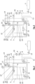
Fig. 1 ist ein erfindungsgemäßes Kryospeichersystem dargestellt, welches einen Kryobehälter umfasst, der einen Innentank 1 und einen Außenbehälter 2 umfasst, mit einem Isolationsraum als Zwischenraum zwischen Innentank 1 und Außenbehälter 2. - Das Kryospeichersystem kann tiefkalte kryogene Flüssigkeit aus dem Innentank 1 mittels einer leistungsgesteuerten druckerhöhenden Kryopumpe 21 über eine Druckleitung 22 der Kryopumpe, die in eine Entnahmeleitung 27 übergeht und an einer Leitungsverbindung 3 in eine Versorgungsleitung 4 mündet, zu einem Verbraucher 5 fördern.
- Die Kryopumpe 21 ist vollständig von kryogenem Fluid umgeben, d.h. auch der Antrieb der Pumpe 21 arbeitet bei tiefkalten Temperaturen, wodurch eine geringe elektrische Leistungsaufnahme für die Kaltgasverdichtung ermöglicht wird.
- Gas kann zudem durch Öffnen eines GH2 Tankventils 15 und/oder Flüssigkeit durch Öffnen eines LH2 Tankventils 16 aus dem Innentank 1 in die Entnahmeleitung 27 strömen. Gas kann dabei über eine kombinierte Sicherheits- und Gasentnahmeleitung 18 dem Innentank 1 entnommen werden. Nach dem GH2 Tankventil 15 kann ein Rückschlagvenil 17 für die Gasentnahme vorgesehen sein. Aus der kombinierte Sicherheits- und Gasentnahmeleitung 18 kann Gas auch durch ein Druckentlastungssicherheitsventil 19 nach außen abgegeben werden.
- Das kryogene Fluid, insbesondere flüssiger Wasserstoff, wird nach der Entnahme aus dem Innentank 1, insbesondere nach der Kryopumpe 21 und nach den Tankventilen 15, 16, über einen Wärmeübertrager 7 geleitet, dabei durch Wärmezufuhr, vorzugweise mittels Kühlwassers 11 des Verbrauchers 5, vollständig in die Gasphase überführt und zugleich für den Verbraucher 5 ausreichend erwärmt. Die Kryopumpe 21 fördert den Wasserstoff bei Bedarf mit höherem Druck zum Verbraucher 5 als im Innentank 1 vorliegt. Durch die Entnahme von Kraftstoff aus dem Kryospeichersystem sinkt der Druck und die Kraftstoffmenge in dessen Innentank 1.
- Um eine eventuelle auftretende schwankende Förderleistung der Kryopumpe 21 auszugleichen, kann zusätzlich zwischen Pumpe 21 und Verbraucher 5, insbesondere in der Versorgungsleitung 4, ein Pufferbehälter 8 für warmen Wasserstoff angeordnet werden. In der Versorgungsleitung 4 kann vor dem Verbraucher 5 ein Absperrventil 12 für die H2-Versorgung zum Verbraucher 5 angeordnet sein.
- Das Kryospeichersystem kann über eine Betankungsschnittstelle 14 betankt werden. Die Betankung kann abschnittsweise über die Entnahmeleitung 27 und eine Einlassleitung 20 in den Innentank 1 erfolgen, bevorzugt in den Bereich gasförmigen Wasserstoffs des Innentanks 1.
- Wie in
Fig. 1 - 5 dargestellt, kann ein federbelastetes Rückschlagventil 25 in der Einlassleitung 20 in den Innentank 1 angeordnet sein, wobei die Einlassleitung 20 von einer Leitung abzweigt, die durch eine das von der Kryopumpe 21 geförderte Medium ableitenden Druckleitung 22 und der Entnahmeleitung 27 gebildet wird. - Die Betankung kann dann über die Entnahmeleitung 27 und über das federbelastete Rückschlagventil 25 und über die Einlassleitung 20 in den Innentank 1 erfolgen.
- Besteht Bedarf den Druck im Innentank 1 des Kryospeichersystems zu erhöhen bzw. zu halten, kann Gas über Ventil 13 in einer Gasrückführleitung 6, die an der Leitungsverbindung 3 von der Entnahmeleitung 27 nach dem Wärmetauscher 7 abzweigt, zurück in den Innentank 1 transferiert werden. Um den Druck für die Gasrückführung in den Innentank 1 zu begrenzen, kann bei Bedarf ein Druckminderer 9 mit nachgeschaltetem Drucksicherheitsventil 10 in der Gasrückführleitung 6 verbaut werden.
- Während
Fig. 1 eine einstufige Druckerhöhung mit Gasrückführung zeigt, zeigt dieFig. 2 eine Variante der Erfindung mit einer seriellen Pumpanordnung für eine zweistufige Druckerhöhung mit Gasrückführung. - Besteht Bedarf für sehr hohe Versorgungsdrücke (überkritisch, zum Beispiel mehr als 20 bar) kann der ersten Kryopumpstufe mindestens eine weitere Kryopumpstufe in Reihe nachgeschaltet werden (vgl.
Fig. 2 ). Dabei wird der Enddruck der ersten Kryopumpe 21 zum Ansaugdruck der zweiten Kryopumpe 21. Die serielle Verschaltung ermöglicht höhere Enddrücke bei gleichzeitig niedriger Energieaufnahme für die Verdichtung des Kaltgases. Alternativ kann einer Kryopumpe 21 und dem Wärmeübertrager 7 auch außerhalb vom Tanksystem ein warmer Kompressor für die finale Verdichtung folgen. -
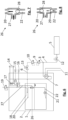
Fig. 3 zeigt an Stelle der Förderpumpe eine besondere Ausführung der Pumpe in Form einer linear angetriebenen doppelseitig-verdrängenden Kryopumpe 21, mit zwei sich gegenüberliegenden Verdrängungsarbeitsräumen, mit jeweils separaten Ansaug- und Auslassstutzen für eine beidseitige Fluidförderung. Die Kryopumpe 21 ist somit als Linearpumpe ausgebildet, die das gespeicherte Medium beidseitig fördert - inFig. 3 lediglich in Form des flüssigen Mediums. -
Fig. 4 zeigt eine Variante einer linear angetriebenen doppelseitig-verdrängenden Kryopumpe 21 mit separaten Ansaugstutzen (wieFig. 3 ), jedoch mit einseitig (inFig. 4 an der linken Seite der Linearförderpumpe) einem Schaltventil 23, zur wahlweisen Förderung von Flüssigkeit oder Gas. An der gegenüberliegenden zweiten Seite der Pumpe erfolgt nur eine Flüssigkeitsförderung. Im Übrigen ist das Kryospeichersystem gleich ausgebildet, wie die Varianten derFig. 1 bis Fig. 3 . - Durch Einbau von zusätzlichem Equipment im Innentank (Kryoventil(e), Rohrleitung(en)) kann durch gesteuerte wechselnde Ventilschaltstellung wahlweise Gas oder Flüssigkeit zum jeweiligen Ansaugstutzen zuströmen. Durch die Ventilsteuerung 23, zum Beispiel in
Fig. 4 , ist das Verhältnis von Gas- zu Flüssigkeitsentnahme veränderbar und somit auch das Verhältnis von Massestrom zum Verbraucher 5 zur Druckabsenkung im Innentank 1. Die Auswahlmöglichkeit zwischen Gas- oder Flüssigkeitsentnahme bietet einen zusätzlichen Freiheitsgrad, denn damit ist das Verhältnis von Massestrom zum Verbraucher 5 zur Druckabsenkung im Innentank 1 nicht mehr annähernd konstant und die jeweilige Größe nur über die Pumpfrequenz veränderbar, sondern jeweils flexibel. - Bei geöffnetem Ventil 23 flutet LH2 das Rohr bis zum Ansaugstutzen der Kryopumpe 21 und die Gasentnahmeleitung 24 hinauf bis auf Höhe des LH2-Levels (als Folge des hydrostatischen Ausgleichs). Wird das Ventil 23 geschlossen, wird zunächst der restliche LH2 aus der Rohrleitung des Ansaugstutzens gefördert, bevor gasförmiger Wasserstoff von oben durch die Gasentnahmeleitung 24 zum Ansaugstutzen nachströmt.
- Gas kann somit über eine Gasentnahmeleitung 24 als verlängerter Ansaugstutzen der Kryopumpe 21 aus dem Innentank 1 entnommen werden. Durch ein pumpnahes Schaltventil 23 für das Umschalten von LH2 auf GH2, kann wahlweise Flüssigkeit oder Gas aus dem Innentank 1 durch die Pumpe 21 gefördert werden.
- Wird eine Linearpumpe (
Fig. 3 - 6 ) eingesetzt, die beidseitig fördert, ergeben sich verschiedene mögliche Varianten der Extraktion: Der linke und rechte Förderstrom können beispielsweise beide lediglich LH2, also flüssigen Wasserstoff, fördern, oder eine der beiden Seiten, beispielsweise links, wahlweise GH2 oder LH2 und die andere Seite lediglich LH2, oder beide Seiten können wahlweise GH2 oder LH2, also Gas oder Flüssigkeit, fördern, so dass das geförderte Medium insgesamt von 100% GH2 bis zu 100% LH2-Förderung variabel ist. -
Fig. 4 zeigt von diesen Möglichkeiten eine Variante mit linear angetriebener doppelseitig-verdrängender Kryopumpe 21 mit verbundenen Ansaugstutzen, mit wahlweiser Förderung von Flüssigkeit oder Gas auf einer, nämlich hier der linken, Pumpenseite. -
Fig. 5 zeigt eine Variante einer linear angetriebenen doppelseitig-verdrängenden Kryopumpe 21 mit separaten Ansaugstutzen, die beide wahlweise zur Förderung von Flüssigkeit und/oder Gas eingerichtet sind. An jedem der beiden Ansaugstutzen der Kryopumpe 21 ist jeweils ein Schaltventil 23 für das Umschalten von LH2 auf GH2 angeordnet. - In den bisher beschriebenen Anordnungen ermöglicht jeweils ein federbelastetes Rückschlagventil 25 in der Befüllleitung im Innentank die Betankung mit Umgehung der Pumpe 21 und bevorzugt in den Gasraum. Es besteht dabei die Anforderung, dass der Betankungsdruck für das Öffnen des federbelasteten Rückschlagventils 25 höher ist, als der maximale Förderdruck der Kryopumpe 21. Das Rückschlagventil 25 bewirkt zwar einen zusätzlichen Strömungswiderstand für die Betankung aber vermeidet einen für den Förderstrom der Kryopumpe 21 zum Verbraucher 5.
-
Fig. 6 zeigt eine andere Konfiguration der Ventile zur Betankung, nämlich ein Wechselventil 26, das bevorzugt im Innentank 1 angeordnet ist, und inFig. 1 mit einer Schwebekörperposition bei Entnahme durch die Kryopumpe 21 dargestellt ist. Ein federbelastetes Rückschlagventil 25 ist in dieser Ausführungsform nicht erforderlich. - In der das geförderte Medium ableitenden Druckleitung 22 der Kryopumpe 21 ist das Wechselventil 26 angeordnet, wobei die das geförderte Medium ableitende Druckleitung 22 am Wechselventil 26 in die Einlassleitung 20 in den Innentank 1 übergeht, so dass am Wechselventil 26, je nach Zustand des Wechselventils 26, entweder der Zugang zur Druckleitung 22 geöffnet ist und der Zugang zur Einlassleitung 20 geschlossen ist oder der Zugang zur Druckleitung 22 geschlossen ist und der Zugang zur Einlassleitung 20 geöffnet ist.
- Das Wechselventil weist somit einen Zugang zur Entnahmeleitung 27 auf, der sowohl bei geöffnetem Zugang zur Druckleitung 22 als auch bei geöffnetem Zugang zur Einlassleitung 20 geöffnet ist.
- Das Wechselventil 26 mit integriertem Schwebekörper 28 (vgl.
Fig. 6 - 8 ) stellt eine Realisation einer Umschaltung zwischen Entnahme und Betankung dar. Das Wechselventil 26 ist an der Verbindungsstelle zwischen Druckleitung 22, Entnahmeleitung 27 und Einlassleitung 20 in den Innentank 1 angeordnet. - Der Schwebekörper 28 verbleibt bedingt durch sein Eigengewicht bei Betankung (
Fig. 7 ) in der unteren End-Position und gibt die Einlassleitung 20 zur Befüllung des Innentanks frei. Durch Inbetriebnahme der Kryopumpe 21 wird der Schwebekörper 28 durch den Förderstrom derart angehoben/verlagert, dass er den Einlass der Befüllleitung zum Innentank 1, also der Einlassleitung 20, verschließt (Fig. 8 ), sodass der Förderstrom ausschließlich zum Verbraucher 5 gepumpt wird. - Die Vorteile dieser Alternative sind, dass die Betankung mit geringerem Strömungswiderstand erfolgen kann und Betankungsdruck und maximaler Förderdruck der Kryopumpe 21 voneinander unabhängig sind. Allerdings ergibt sich durch den im Wechselventil 26 integrierten Schwebekörper 28 ein zusätzlicher Strömungswiderstand für den Förderstrom der Kryopumpe 21 zum Verbraucher 5.
- Beide Konfigurationen der Umschaltfunktion, nämlich federbelastetes Rückschlagventil 25 und Wechselventil 26, ermöglichen eine Druckentlastung der angrenzenden Leitungen und der Kryopumpe 21 in den Innentank 1 hinein, wenn sich eingeschlossenes Fluid durch Erwärmung ausdehnt.
-
Fig. 7 zeigt somit die Strömung im Wechselventil 26 bei Betankung.
Das Eigengewicht des Schwebekörpers 28 hält bei einer Betankung den Schwebekörper 28 in einer unteren End-Position, so dass die Einlassleitung 20 zur Befüllung des Innentanks 1 freigegeben ist. -
Fig. 8 zeigt die Strömung im Wechselventil 26 bei Entnahme über die Kryopumpe 21. Bei einer Inbetriebnahme der Kryopumpe 21 wird der Schwebekörper 28 durch den Förderstrom vom Ventilsitz 29 angehoben, so dass er die Einlassleitung 20 zum Innentank 1 verschließt und der Förderstrom ausschließlich zum Verbraucher 5 gepumpt wird. -
- 1
- Innentank des Primärspeichersystems
- 2
- Außenbehälter
- 3
- Leitungsverbindung
- 4
- Versorgungsleitung
- 5
- Verbraucher
- 6
- Gasrückführleitung
- 7
- Wärmeübertrager
- 8
- Pufferbehälter
- 9
- Druckminderer
- 10
- Drucksicherheitsventil
- 11
- Kühlwasserkreislauf
- 12
- Absperrventil für H2 Versorgung zum Verbraucher
- 13
- Absperrventil für Gasrückführung zum Innentank
- 14
- Schnittstelle für Betankung
- 15
- GH2 Tankventil
- 16
- LH2 Tankventil
- 17
- Rückschlagventil für die Gasentnahme
- 18
- kombinierte Sicherheits- und Gasentnahmeleitung
- 19
- Druckentlastungssicherheitsventil
- 20
- LH2 Einlassleitung in den Innentank
- 21
- Kryopumpe(n)
- 22
- Druckleitung der Kryopumpe
- 23
- Pumpnahes Schaltventil für das Umschalten von LH2 auf GH2
- 24
- Gasentnahmeleitung als verlängerter Ansaugstutzen der Kryopumpe
- 25
- Weiteres Rückschlagventil
- 26
- Wechselventil
- 27
- Entnahmeleitung
- 28
- Schwebekörper
- 29
- Ventilsitz
Claims (10)
- Kryospeichersystem, umfassend einen Kryobehälter zur Speicherung von Wasserstoff, mit einem Innentank (1) und einem Außenbehälter (2),
dadurch gekennzeichnet, dass im Innentank (1) des Kryobehälters mindestens eine Kryopumpe (21) angeordnet ist, wobei die Kryopumpe (21) flüssigen und/oder gasförmigen Wasserstoff ein- oder mehrstufig über eine Entnahmeleitung (27) zu einem Verbraucher (5) fördert, mit höherem Druck als dem Druck im Innentank (1), wobei der Innentank (1) über eine Betankungsschnittstelle (14) betankt werden kann, wobei die Betankung zumindest abschnittsweise über die Entnahmeleitung (27) erfolgt, wobei die Betankung über ein federbelastetes Rückschlagventil (25) oder ein Wechselventil (26) in den Innentank (1) erfolgt. - Kryospeichersystem nach Anspruch 1,
dadurch gekennzeichnet, dass das federbelastete Rückschlagventil (25) in einer Einlassleitung (20) in den Innentank (1) angeordnet ist, die von einer Leitung abzweigt, die durch eine das von der Kryopumpe (21) geförderte Medium ableitenden Druckleitung (22) und der Entnahmeleitung (27) gebildet wird. - Kryospeichersystem nach Anspruch 1,
dadurch gekennzeichnet, dass in einer das geförderte Medium ableitenden Druckleitung (22) der Kryopumpe (21) das Wechselventil (26) angeordnet ist, wobei die das geförderte Medium ableitende Druckleitung (22) am Wechselventil (26) in eine Einlassleitung (20) in den Innentank (1) übergeht, so dass am Wechselventil (26), je nach Zustand des Wechselventils (26), entweder der Zugang zur Druckleitung (22) geöffnet ist und der Zugang zur Einlassleitung (20) geschlossen ist oder der Zugang zur Druckleitung (22) geschlossen ist und der Zugang zur Einlassleitung (20) geöffnet ist. - Kryospeichersystem nach Anspruch 3,
dadurch gekennzeichnet, dass das Wechselventil einen Zugang zur Entnahmeleitung (27) aufweist, der sowohl bei geöffnetem Zugang zur Druckleitung (22) als auch bei geöffnetem Zugang zur Einlassleitung (20) geöffnet ist. - Kryospeichersystem nach Anspruch 3 oder 4,
dadurch gekennzeichnet, dass das Wechselventil (26) einen integrierten Schwebekörper (28) aufweist, wobei das Eigengewicht des Schwebekörpers (28) den Schwebekörper (28) in einer unteren End-Position hält, so dass die Einlassleitung (20) zur Befüllung des Innentanks (1) freigegeben ist, wobei bei einer Inbetriebnahme der Kryopumpe (21) der Schwebekörper (28) durch den Förderstrom angehoben wird, so dass er die Einlassleitung (20) zum Innentank (1) verschließt und der Förderstrom ausschließlich zum Verbraucher (5) gepumpt wird. - Kryospeichersystem nach zumindest einem der vorhergehenden Ansprüche,
dadurch gekennzeichnet, dass die Kryopumpe (21) als Linearpumpe ausgebildet ist, die beidseitig fördert. - Kryospeichersystem nach Anspruch 6,
dadurch gekennzeichnet, dass der linke und/oder der rechte Förderstrom der Linearpumpe dazu ausgebildet ist, wahlweise gasförmigen oder flüssigen Wasserstoff zu fördern, bevorzugt über ein pumpnahes Absperrventil (23) für das Umschalten von gasförmigem auf flüssigen Wasserstoff. - Kryospeichersystem nach zumindest einem der vorhergehenden Ansprüche,
dadurch gekennzeichnet, dass der Kryobehälter dazu eingerichtet ist, dass ein Teilstrom des erwärmten Wasserstoffs, also des entnommenen Wasserstoffs nach einem Wärmeübertrager (7), über eine Gasrückführleitung (6) in den Innentank (1) zurückgeführt werden kann, um den Innentankdruck zu erhöhen, bevorzugt über ein Absperrventil (13) für die Gasrückführung zum Innentank (1). - Kryospeichersystem nach Anspruch 8,
dadurch gekennzeichnet, dass ein Druckminderer (9), bevorzugt mit nachgeschaltetem Drucksicherheitsventil (10), in der Gasrückführleitung (6) für die Gasrückführung zum Innentank (1) verbaut ist. - Kryospeichersystem nach zumindest einem der vorhergehenden Ansprüche,
dadurch gekennzeichnet, dass zwischen der Kryopumpe (21) und dem Verbraucher (5) ein Pufferbehälter (8) für warmen Wasserstoff angeordnet ist.
Priority Applications (3)
| Application Number | Priority Date | Filing Date | Title |
|---|---|---|---|
| EP23151491.0A EP4400760B1 (de) | 2023-01-13 | 2023-01-13 | Kryospeichersystem |
| CN202311575390.0A CN118346913A (zh) | 2023-01-13 | 2023-11-23 | 低温存储器系统 |
| US18/527,318 US12331890B2 (en) | 2023-01-13 | 2023-12-03 | Cryogenic storage system |
Applications Claiming Priority (1)
| Application Number | Priority Date | Filing Date | Title |
|---|---|---|---|
| EP23151491.0A EP4400760B1 (de) | 2023-01-13 | 2023-01-13 | Kryospeichersystem |
Publications (2)
| Publication Number | Publication Date |
|---|---|
| EP4400760A1 true EP4400760A1 (de) | 2024-07-17 |
| EP4400760B1 EP4400760B1 (de) | 2025-09-17 |
Family
ID=84981454
Family Applications (1)
| Application Number | Title | Priority Date | Filing Date |
|---|---|---|---|
| EP23151491.0A Active EP4400760B1 (de) | 2023-01-13 | 2023-01-13 | Kryospeichersystem |
Country Status (3)
| Country | Link |
|---|---|
| US (1) | US12331890B2 (de) |
| EP (1) | EP4400760B1 (de) |
| CN (1) | CN118346913A (de) |
Citations (6)
| Publication number | Priority date | Publication date | Assignee | Title |
|---|---|---|---|---|
| DE4320556A1 (de) * | 1993-06-21 | 1994-12-22 | Linde Ag | Speicherbehälter für kryogene Medien |
| US6526760B2 (en) * | 2000-12-07 | 2003-03-04 | Bayerische Motoren Werke Aktiengesellschaft | Method and apparatus for conveying a cryogenically-stored fuel |
| US20120317995A1 (en) | 2011-06-18 | 2012-12-20 | Magna Steyr Fahrzeugtechnik Ag & Co Kg | Pump for conveying a cryogenic fluid |
| EP3236132A1 (de) * | 2016-04-22 | 2017-10-25 | Salzburger Aluminium Aktiengesellschaft | Tanksystem |
| DE102019205601A1 (de) * | 2019-04-17 | 2020-10-22 | Robert Bosch Gmbh | Verfahren zum Betreiben eines Kraftstoffsystems sowie Kraftstoffsystem |
| US11415084B2 (en) * | 2019-04-09 | 2022-08-16 | Magna Steyr Fahrzeugtechnik Ag & Co Kg | Storage tank for cryogenic liquid gas |
Family Cites Families (7)
| Publication number | Priority date | Publication date | Assignee | Title |
|---|---|---|---|---|
| US5771946A (en) * | 1992-12-07 | 1998-06-30 | Chicago Bridge & Iron Technical Services Company | Method and apparatus for fueling vehicles with liquefied cryogenic fuel |
| US6314947B1 (en) * | 1999-10-13 | 2001-11-13 | Walbro Corporation | Fuel delivery system |
| US7410348B2 (en) * | 2005-08-03 | 2008-08-12 | Air Products And Chemicals, Inc. | Multi-speed compressor/pump apparatus |
| US9752728B2 (en) * | 2012-12-20 | 2017-09-05 | General Electric Company | Cryogenic tank assembly |
| WO2015077784A1 (en) * | 2013-11-25 | 2015-05-28 | Chart Inc. | Pump column baffle for lng pump |
| DE102017219784A1 (de) * | 2017-11-07 | 2019-05-09 | Robert Bosch Gmbh | Kraftstofffördereinrichtung für kryogene Kraftstoffe, Verfahren zum Betreiben einer Kraftstofffördereinrichtung für kryogene Kraftstoffe |
| US12135112B2 (en) * | 2021-09-03 | 2024-11-05 | China Energy Investment Corporation Limited | System having cryotank with offset pump housing, method of making and method of using the same |
-
2023
- 2023-01-13 EP EP23151491.0A patent/EP4400760B1/de active Active
- 2023-11-23 CN CN202311575390.0A patent/CN118346913A/zh active Pending
- 2023-12-03 US US18/527,318 patent/US12331890B2/en active Active
Patent Citations (6)
| Publication number | Priority date | Publication date | Assignee | Title |
|---|---|---|---|---|
| DE4320556A1 (de) * | 1993-06-21 | 1994-12-22 | Linde Ag | Speicherbehälter für kryogene Medien |
| US6526760B2 (en) * | 2000-12-07 | 2003-03-04 | Bayerische Motoren Werke Aktiengesellschaft | Method and apparatus for conveying a cryogenically-stored fuel |
| US20120317995A1 (en) | 2011-06-18 | 2012-12-20 | Magna Steyr Fahrzeugtechnik Ag & Co Kg | Pump for conveying a cryogenic fluid |
| EP3236132A1 (de) * | 2016-04-22 | 2017-10-25 | Salzburger Aluminium Aktiengesellschaft | Tanksystem |
| US11415084B2 (en) * | 2019-04-09 | 2022-08-16 | Magna Steyr Fahrzeugtechnik Ag & Co Kg | Storage tank for cryogenic liquid gas |
| DE102019205601A1 (de) * | 2019-04-17 | 2020-10-22 | Robert Bosch Gmbh | Verfahren zum Betreiben eines Kraftstoffsystems sowie Kraftstoffsystem |
Also Published As
| Publication number | Publication date |
|---|---|
| US12331890B2 (en) | 2025-06-17 |
| CN118346913A (zh) | 2024-07-16 |
| US20240240757A1 (en) | 2024-07-18 |
| EP4400760B1 (de) | 2025-09-17 |
Similar Documents
| Publication | Publication Date | Title |
|---|---|---|
| DE102020206689B3 (de) | Kryogen-Speichersystem | |
| EP3722652B1 (de) | Speicherbehälter für tiefkaltes flüssiggas | |
| DE69304507T2 (de) | Verfahren und Apparat zur Abgabe einer kontinuierliche Menge eines Gases in einem grossen Strömungsbereich | |
| DE102006025656B4 (de) | Vorrichtung zur Kraftstoffspeicherung und -förderung von kryogenem Kraftstoff | |
| EP3715261B1 (de) | Treibstoffentnahmesystem, treibstofftankvorrichtung mit treibstoffentnahmesystem und brennstoffzellensystem mit treibstoffentnahmesystem | |
| EP2035739A1 (de) | Verfahren zum betrieb einer vorrichtung zur befüllung eines behälters mit kryogen gespeichertem kraftstoff | |
| DE10040679A1 (de) | Vorrichtung und Verfahren zur druckgeregelten Versorgung aus einem Flüssiggastank | |
| EP4400760B1 (de) | Kryospeichersystem | |
| EP4392703B1 (de) | Verfahren und fördervorrichtung | |
| EP4400759A1 (de) | Kryospeichersystem | |
| DE10060791A1 (de) | Verfahren und Vorrichtung zur Förderung eines kryogen gespeicherten Kraftstoffes | |
| EP4155601A1 (de) | Kryogen-speichersystem | |
| DE102016203200A1 (de) | Verfahren zum Abkühlen eines ersten kryogenen Druckbehälters | |
| EP2118557B1 (de) | Speicherbehälter für tiefkaltes flüssiggas mit einer entnahmevorrichtung | |
| EP4409195B1 (de) | Kryotank | |
| EP2604840A1 (de) | Förder-Aggregat für kryogene Flüssigkeiten | |
| DE102018212117A1 (de) | Vorratstank, Kraftstofffördereinrichtung und Verfahren zur Regulierung des Druckes in einem Vorratstank | |
| EP1090251A1 (de) | System zum versorgen eines verbrauchers mit einen kryogenem medium | |
| DE102007052259A1 (de) | Kraftstoffversorgungseinrichtung für ein mit Wasserstoff zu betreibendes Kraftfahrzeug | |
| WO2019115164A1 (de) | Kraftstofffördereinrichtung für eine brennkraftmaschine | |
| EP4400758A1 (de) | Multi-kryospeichersystem | |
| DE102016014927A1 (de) | Kraftstoffsystem mit einem Tank zum Speichern von Flüssiggas als Kraftstoff | |
| DE102024120662B3 (de) | Vorrichtung und Verfahren zum Verdichten eines Mediums | |
| DE102020200611A1 (de) | Brennstoffzellensystem | |
| EP3961082B1 (de) | Anschlussgarnitur, tanksystem und zapfsäule |
Legal Events
| Date | Code | Title | Description |
|---|---|---|---|
| PUAI | Public reference made under article 153(3) epc to a published international application that has entered the european phase |
Free format text: ORIGINAL CODE: 0009012 |
|
| STAA | Information on the status of an ep patent application or granted ep patent |
Free format text: STATUS: REQUEST FOR EXAMINATION WAS MADE |
|
| 17P | Request for examination filed |
Effective date: 20240124 |
|
| AK | Designated contracting states |
Kind code of ref document: A1 Designated state(s): AL AT BE BG CH CY CZ DE DK EE ES FI FR GB GR HR HU IE IS IT LI LT LU LV MC ME MK MT NL NO PL PT RO RS SE SI SK SM TR |
|
| GRAP | Despatch of communication of intention to grant a patent |
Free format text: ORIGINAL CODE: EPIDOSNIGR1 |
|
| STAA | Information on the status of an ep patent application or granted ep patent |
Free format text: STATUS: GRANT OF PATENT IS INTENDED |
|
| RIC1 | Information provided on ipc code assigned before grant |
Ipc: F17C 9/00 20060101ALI20250417BHEP Ipc: F17C 6/00 20060101AFI20250417BHEP |
|
| INTG | Intention to grant announced |
Effective date: 20250508 |
|
| GRAS | Grant fee paid |
Free format text: ORIGINAL CODE: EPIDOSNIGR3 |
|
| GRAA | (expected) grant |
Free format text: ORIGINAL CODE: 0009210 |
|
| STAA | Information on the status of an ep patent application or granted ep patent |
Free format text: STATUS: THE PATENT HAS BEEN GRANTED |
|
| AK | Designated contracting states |
Kind code of ref document: B1 Designated state(s): AL AT BE BG CH CY CZ DE DK EE ES FI FR GB GR HR HU IE IS IT LI LT LU LV MC ME MK MT NL NO PL PT RO RS SE SI SK SM TR |
|
| REG | Reference to a national code |
Ref country code: GB Ref legal event code: FG4D Free format text: NOT ENGLISH |
|
| REG | Reference to a national code |
Ref country code: CH Ref legal event code: EP |
|
| REG | Reference to a national code |
Ref country code: IE Ref legal event code: FG4D Free format text: LANGUAGE OF EP DOCUMENT: GERMAN |
|
| REG | Reference to a national code |
Ref country code: DE Ref legal event code: R096 Ref document number: 502023001788 Country of ref document: DE |
|
| PG25 | Lapsed in a contracting state [announced via postgrant information from national office to epo] |
Ref country code: NO Free format text: LAPSE BECAUSE OF FAILURE TO SUBMIT A TRANSLATION OF THE DESCRIPTION OR TO PAY THE FEE WITHIN THE PRESCRIBED TIME-LIMIT Effective date: 20251217 |
|
| REG | Reference to a national code |
Ref country code: LT Ref legal event code: MG9D |
|
| PG25 | Lapsed in a contracting state [announced via postgrant information from national office to epo] |
Ref country code: FI Free format text: LAPSE BECAUSE OF FAILURE TO SUBMIT A TRANSLATION OF THE DESCRIPTION OR TO PAY THE FEE WITHIN THE PRESCRIBED TIME-LIMIT Effective date: 20250917 |
|
| PG25 | Lapsed in a contracting state [announced via postgrant information from national office to epo] |
Ref country code: HR Free format text: LAPSE BECAUSE OF FAILURE TO SUBMIT A TRANSLATION OF THE DESCRIPTION OR TO PAY THE FEE WITHIN THE PRESCRIBED TIME-LIMIT Effective date: 20250917 |
|
| PG25 | Lapsed in a contracting state [announced via postgrant information from national office to epo] |
Ref country code: GR Free format text: LAPSE BECAUSE OF FAILURE TO SUBMIT A TRANSLATION OF THE DESCRIPTION OR TO PAY THE FEE WITHIN THE PRESCRIBED TIME-LIMIT Effective date: 20251218 |
|
| PG25 | Lapsed in a contracting state [announced via postgrant information from national office to epo] |
Ref country code: SE Free format text: LAPSE BECAUSE OF FAILURE TO SUBMIT A TRANSLATION OF THE DESCRIPTION OR TO PAY THE FEE WITHIN THE PRESCRIBED TIME-LIMIT Effective date: 20250917 |
|
| REG | Reference to a national code |
Ref country code: NL Ref legal event code: MP Effective date: 20250917 |
|
| PG25 | Lapsed in a contracting state [announced via postgrant information from national office to epo] |
Ref country code: LV Free format text: LAPSE BECAUSE OF FAILURE TO SUBMIT A TRANSLATION OF THE DESCRIPTION OR TO PAY THE FEE WITHIN THE PRESCRIBED TIME-LIMIT Effective date: 20250917 |
|
| PG25 | Lapsed in a contracting state [announced via postgrant information from national office to epo] |
Ref country code: BG Free format text: LAPSE BECAUSE OF FAILURE TO SUBMIT A TRANSLATION OF THE DESCRIPTION OR TO PAY THE FEE WITHIN THE PRESCRIBED TIME-LIMIT Effective date: 20250917 |
|
| PG25 | Lapsed in a contracting state [announced via postgrant information from national office to epo] |
Ref country code: RS Free format text: LAPSE BECAUSE OF FAILURE TO SUBMIT A TRANSLATION OF THE DESCRIPTION OR TO PAY THE FEE WITHIN THE PRESCRIBED TIME-LIMIT Effective date: 20251217 |
|
| PG25 | Lapsed in a contracting state [announced via postgrant information from national office to epo] |
Ref country code: NL Free format text: LAPSE BECAUSE OF FAILURE TO SUBMIT A TRANSLATION OF THE DESCRIPTION OR TO PAY THE FEE WITHIN THE PRESCRIBED TIME-LIMIT Effective date: 20250917 |
|
| PG25 | Lapsed in a contracting state [announced via postgrant information from national office to epo] |
Ref country code: SM Free format text: LAPSE BECAUSE OF FAILURE TO SUBMIT A TRANSLATION OF THE DESCRIPTION OR TO PAY THE FEE WITHIN THE PRESCRIBED TIME-LIMIT Effective date: 20250917 |
|
| PG25 | Lapsed in a contracting state [announced via postgrant information from national office to epo] |
Ref country code: ES Free format text: LAPSE BECAUSE OF FAILURE TO SUBMIT A TRANSLATION OF THE DESCRIPTION OR TO PAY THE FEE WITHIN THE PRESCRIBED TIME-LIMIT Effective date: 20250917 |
|
| PGFP | Annual fee paid to national office [announced via postgrant information from national office to epo] |
Ref country code: DE Payment date: 20260121 Year of fee payment: 4 |
|
| PGFP | Annual fee paid to national office [announced via postgrant information from national office to epo] |
Ref country code: AT Payment date: 20260301 Year of fee payment: 4 |
|
| PG25 | Lapsed in a contracting state [announced via postgrant information from national office to epo] |
Ref country code: IT Free format text: LAPSE BECAUSE OF FAILURE TO SUBMIT A TRANSLATION OF THE DESCRIPTION OR TO PAY THE FEE WITHIN THE PRESCRIBED TIME-LIMIT Effective date: 20250917 |
|
| PG25 | Lapsed in a contracting state [announced via postgrant information from national office to epo] |
Ref country code: IS Free format text: LAPSE BECAUSE OF FAILURE TO SUBMIT A TRANSLATION OF THE DESCRIPTION OR TO PAY THE FEE WITHIN THE PRESCRIBED TIME-LIMIT Effective date: 20260117 |
|
| PGFP | Annual fee paid to national office [announced via postgrant information from national office to epo] |
Ref country code: FR Payment date: 20260123 Year of fee payment: 4 |
|
| PG25 | Lapsed in a contracting state [announced via postgrant information from national office to epo] |
Ref country code: CZ Free format text: LAPSE BECAUSE OF FAILURE TO SUBMIT A TRANSLATION OF THE DESCRIPTION OR TO PAY THE FEE WITHIN THE PRESCRIBED TIME-LIMIT Effective date: 20250917 Ref country code: PT Free format text: LAPSE BECAUSE OF FAILURE TO SUBMIT A TRANSLATION OF THE DESCRIPTION OR TO PAY THE FEE WITHIN THE PRESCRIBED TIME-LIMIT Effective date: 20260119 |
|
| PG25 | Lapsed in a contracting state [announced via postgrant information from national office to epo] |
Ref country code: PL Free format text: LAPSE BECAUSE OF FAILURE TO SUBMIT A TRANSLATION OF THE DESCRIPTION OR TO PAY THE FEE WITHIN THE PRESCRIBED TIME-LIMIT Effective date: 20250917 |
|
| PG25 | Lapsed in a contracting state [announced via postgrant information from national office to epo] |
Ref country code: SK Free format text: LAPSE BECAUSE OF FAILURE TO SUBMIT A TRANSLATION OF THE DESCRIPTION OR TO PAY THE FEE WITHIN THE PRESCRIBED TIME-LIMIT Effective date: 20250917 Ref country code: EE Free format text: LAPSE BECAUSE OF FAILURE TO SUBMIT A TRANSLATION OF THE DESCRIPTION OR TO PAY THE FEE WITHIN THE PRESCRIBED TIME-LIMIT Effective date: 20250917 |