EP4400750A1 - A hydraulic fuse - Google Patents
A hydraulic fuse Download PDFInfo
- Publication number
- EP4400750A1 EP4400750A1 EP23215586.1A EP23215586A EP4400750A1 EP 4400750 A1 EP4400750 A1 EP 4400750A1 EP 23215586 A EP23215586 A EP 23215586A EP 4400750 A1 EP4400750 A1 EP 4400750A1
- Authority
- EP
- European Patent Office
- Prior art keywords
- fuse
- fluid
- fuse element
- hydraulic
- plenum
- Prior art date
- Legal status (The legal status is an assumption and is not a legal conclusion. Google has not performed a legal analysis and makes no representation as to the accuracy of the status listed.)
- Granted
Links
Images




Classifications
-
- F—MECHANICAL ENGINEERING; LIGHTING; HEATING; WEAPONS; BLASTING
- F16—ENGINEERING ELEMENTS AND UNITS; GENERAL MEASURES FOR PRODUCING AND MAINTAINING EFFECTIVE FUNCTIONING OF MACHINES OR INSTALLATIONS; THERMAL INSULATION IN GENERAL
- F16K—VALVES; TAPS; COCKS; ACTUATING-FLOATS; DEVICES FOR VENTING OR AERATING
- F16K17/00—Safety valves; Equalising valves, e.g. pressure relief valves
- F16K17/02—Safety valves; Equalising valves, e.g. pressure relief valves opening on surplus pressure on one side; closing on insufficient pressure on one side
- F16K17/14—Safety valves; Equalising valves, e.g. pressure relief valves opening on surplus pressure on one side; closing on insufficient pressure on one side with fracturing member
-
- F—MECHANICAL ENGINEERING; LIGHTING; HEATING; WEAPONS; BLASTING
- F16—ENGINEERING ELEMENTS AND UNITS; GENERAL MEASURES FOR PRODUCING AND MAINTAINING EFFECTIVE FUNCTIONING OF MACHINES OR INSTALLATIONS; THERMAL INSULATION IN GENERAL
- F16K—VALVES; TAPS; COCKS; ACTUATING-FLOATS; DEVICES FOR VENTING OR AERATING
- F16K17/00—Safety valves; Equalising valves, e.g. pressure relief valves
- F16K17/20—Excess-flow valves
- F16K17/22—Excess-flow valves actuated by the difference of pressure between two places in the flow line
- F16K17/24—Excess-flow valves actuated by the difference of pressure between two places in the flow line acting directly on the cutting-off member
- F16K17/28—Excess-flow valves actuated by the difference of pressure between two places in the flow line acting directly on the cutting-off member operating in one direction only
- F16K17/30—Excess-flow valves actuated by the difference of pressure between two places in the flow line acting directly on the cutting-off member operating in one direction only spring-loaded
-
- F—MECHANICAL ENGINEERING; LIGHTING; HEATING; WEAPONS; BLASTING
- F01—MACHINES OR ENGINES IN GENERAL; ENGINE PLANTS IN GENERAL; STEAM ENGINES
- F01D—NON-POSITIVE DISPLACEMENT MACHINES OR ENGINES, e.g. STEAM TURBINES
- F01D21/00—Shutting-down of machines or engines, e.g. in emergency; Regulating, controlling, or safety means not otherwise provided for
- F01D21/14—Shutting-down of machines or engines, e.g. in emergency; Regulating, controlling, or safety means not otherwise provided for responsive to other specific conditions
-
- B—PERFORMING OPERATIONS; TRANSPORTING
- B33—ADDITIVE MANUFACTURING TECHNOLOGY
- B33Y—ADDITIVE MANUFACTURING, i.e. MANUFACTURING OF THREE-DIMENSIONAL [3D] OBJECTS BY ADDITIVE DEPOSITION, ADDITIVE AGGLOMERATION OR ADDITIVE LAYERING, e.g. BY 3D PRINTING, STEREOLITHOGRAPHY OR SELECTIVE LASER SINTERING
- B33Y80/00—Products made by additive manufacturing
-
- F—MECHANICAL ENGINEERING; LIGHTING; HEATING; WEAPONS; BLASTING
- F16—ENGINEERING ELEMENTS AND UNITS; GENERAL MEASURES FOR PRODUCING AND MAINTAINING EFFECTIVE FUNCTIONING OF MACHINES OR INSTALLATIONS; THERMAL INSULATION IN GENERAL
- F16K—VALVES; TAPS; COCKS; ACTUATING-FLOATS; DEVICES FOR VENTING OR AERATING
- F16K17/00—Safety valves; Equalising valves, e.g. pressure relief valves
- F16K17/02—Safety valves; Equalising valves, e.g. pressure relief valves opening on surplus pressure on one side; closing on insufficient pressure on one side
- F16K17/14—Safety valves; Equalising valves, e.g. pressure relief valves opening on surplus pressure on one side; closing on insufficient pressure on one side with fracturing member
- F16K17/16—Safety valves; Equalising valves, e.g. pressure relief valves opening on surplus pressure on one side; closing on insufficient pressure on one side with fracturing member with fracturing diaphragm ; Rupture discs
-
- F—MECHANICAL ENGINEERING; LIGHTING; HEATING; WEAPONS; BLASTING
- F16—ENGINEERING ELEMENTS AND UNITS; GENERAL MEASURES FOR PRODUCING AND MAINTAINING EFFECTIVE FUNCTIONING OF MACHINES OR INSTALLATIONS; THERMAL INSULATION IN GENERAL
- F16K—VALVES; TAPS; COCKS; ACTUATING-FLOATS; DEVICES FOR VENTING OR AERATING
- F16K2200/00—Details of valves
- F16K2200/20—Common housing having a single inlet, a single outlet and multiple valve members
- F16K2200/204—Common housing having a single inlet, a single outlet and multiple valve members in series
-
- Y—GENERAL TAGGING OF NEW TECHNOLOGICAL DEVELOPMENTS; GENERAL TAGGING OF CROSS-SECTIONAL TECHNOLOGIES SPANNING OVER SEVERAL SECTIONS OF THE IPC; TECHNICAL SUBJECTS COVERED BY FORMER USPC CROSS-REFERENCE ART COLLECTIONS [XRACs] AND DIGESTS
- Y10—TECHNICAL SUBJECTS COVERED BY FORMER USPC
- Y10T—TECHNICAL SUBJECTS COVERED BY FORMER US CLASSIFICATION
- Y10T137/00—Fluid handling
- Y10T137/1624—Destructible or deformable element controlled
- Y10T137/1632—Destructible element
- Y10T137/1692—Rupture disc
- Y10T137/1714—Direct pressure causes disc to burst
Definitions
- the present disclosure relates to a hydraulic fuse and a hydraulic manifold.
- a hydraulic manifold or fluidic tube gallery is a component that allows one or more fluids to enter and exit using various machined, cast, or otherwise manufactured fluid conduits.
- the conduits form a single component which reduces the overall packaging size and complexity when compared to standard pipes or tubes.
- the hydraulic manifold typically forms part of a fluid system, which can include a pump for driving the fluid through the system.
- the manifold in case of an overpressure event, such as that caused by a blocked conduit, the manifold is designed to contain the fluid until another component in the fluid system, such as the pump, fails.
- Overpressure events can also be controlled by other methods, such as by using pressure relief valves or burst disks.
- Pressure relief valves are designed to open at a predetermined pressure to protect fluid systems from overpressure events.
- pressure relief valves are typically bulky, making them unsuitable for certain types of hydraulic manifolds. They can also suffer from reliability issues and can create areas of pressure loss within the fluid system.
- Burst disks are designed to rupture at a predetermined pressure differential across the disk to protect fluid systems from overpressure events. However, burst disks are not as effective when there is a transient pressure differential across the disk, and can burst unreliably.
- a hydraulic fuse comprising: a fuse body defining a plenum, the plenum comprising: an inlet configured to couple to a first fluid location; and an outlet configured to couple to a second fluid location.
- the hydraulic fuse further comprises a first fuse element arranged to close the inlet, the first fuse element configured to open the inlet when a pressure differential between the first fluid location and the plenum reaches a first threshold; and a second fuse element arranged to close the outlet, the second fuse element configured to open the outlet when a pressure differential between the plenum and the second fluid location reaches a second threshold, wherein the first threshold is higher than the second threshold.
- the inlet In an inactive state, the inlet is closed by the first fuse element and the outlet is closed by the second fuse element to prevent fluid flow through the plenum; and in an active state, the pressure differential between the first fluid location and the plenum reaches the first threshold to cause the first fuse element to open and permit fluid flow through the inlet, and the pressure differential between the plenum and the second fluid location reaches the second threshold to cause the second fuse element to open and permit fluid flow through the outlet.
- the first fuse element may be frangible, such that the first fuse element is configured to fracture and open the inlet when the pressure differential between the first fluid location and the plenum reaches the first threshold.
- the second fuse element may be frangible, such that the second fuse element is configured to fracture and open the outlet when the pressure differential between the plenum and the second fluid location reaches the second threshold.
- the first fuse element and/or the second fuse element may be configured to fracture at a respective predetermined fracture point.
- the first fuse element and/or the second fuse element may be configured to fracture in a brittle manner.
- the first fuse element and/or the second fuse element may be configured to fracture in a ductile manner.
- the first fuse element and the second fuse element may be integrally formed with the fuse body.
- the first fuse element and the second fuse element may each comprise a respective retention feature configured to retain the first fuse element and the second fuse element within the plenum in the active state.
- the retention feature may be larger than the inlet and outlet.
- the first fuse element and/or the second fuse element may be flexibly attached to the fuse body, such that in the active state, the first fuse element and/or the second fuse element may be configured to bend and remain attached to the fuse body to provide the retention feature.
- the first fuse element and/or the second fuse element may comprise a plurality of ridges formed on a surface facing into the plenum.
- the first fuse element and the second fuse element may be contained within a volume circumscribed by the fuse body.
- the first fuse element and the fuse body may form a substantially continuous fluid-washed surface facing the first fluid location
- the second fuse element and the fuse body may form a substantially continuous fluid-washed surface facing the second fluid location
- the hydraulic fuse may be formed by an additive manufacturing process.
- the hydraulic fuse may further comprise: an extraction hole opening into the plenum; and a sealing element configured to close the extraction hole.
- a hydraulic manifold comprising: a first fluid conduit and a second fluid conduit separated by a manifold wall; and a hydraulic fuse according to the first aspect, wherein the hydraulic fuse is disposed in the manifold wall between the first fluid conduit and the second fluid conduit, such that the first fluid location is in the first fluid conduit and the second fluid location is in the second fluid conduit.
- the hydraulic fuse may be integrally formed with the manifold wall.
- the hydraulic manifold may be formed by an additive manufacturing process.
- a hydraulic manifold comprising: a fluid conduit defined by a manifold wall; and a hydraulic fuse according to the first aspect; wherein the hydraulic fuse is attached to the manifold wall, such that the first fluid location is in the fluid conduit and the second fluid location is an environment surrounding the hydraulic manifold.
- the hydraulic fuse may be integrally formed with the manifold wall.
- the hydraulic manifold may be formed by an additive manufacturing process.
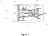
- a gas turbine engine is generally indicated at 10, having a principal and rotational axis 11.
- the engine 10 comprises, in axial flow series, an air intake 12, a propulsive fan 13, an intermediate pressure compressor 14, a high-pressure compressor 15, combustion equipment 16, a high-pressure turbine 17, an intermediate pressure turbine 18, a low-pressure turbine 19 and an exhaust nozzle 20.
- a nacelle 21 generally surrounds the engine 10 and defines both the intake 12 and the exhaust nozzle 20.
- the gas turbine engine 10 works in the conventional manner so that air entering the intake 12 is accelerated by the fan 13 to produce two air flows: a first air flow into the intermediate pressure compressor 14 and a second air flow which passes through a bypass duct 22 to provide propulsive thrust.
- the intermediate pressure compressor 14 compresses the air flow directed into it before delivering that air to the high-pressure compressor 15 where further compression takes place.
- the compressed air exhausted from the high-pressure compressor 15 is directed into the combustion equipment 16 where it is mixed with fuel and the mixture combusted.
- the resultant hot combustion products then expand through, and thereby drive the high, intermediate and low-pressure turbines 17, 18, 19 before being exhausted through the nozzle 20 to provide additional propulsive thrust.
- the high 17, intermediate 18 and low 19 pressure turbines drive respectively the high-pressure compressor 15, intermediate pressure compressor 14 and fan 13, each by suitable interconnecting shaft.
- gas turbine engines to which the present disclosure may be applied may have alternative configurations.
- such engines may have an alternative number of interconnecting shafts (e.g., two) and/or an alternative number of compressors and/or turbines.
- the engine may comprise a gearbox provided in the drive train from a turbine to a compressor and/or fan.
- a hydraulic fuse can be used to mitigate fluid overpressure events in the system in case of system failure, for example caused by blockages.
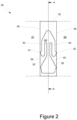
- a first example of a hydraulic fuse according to the present disclosure is shown in Figure 2 .
- the hydraulic fuse 30 comprises a fuse body 32, a first fuse element 39, and a second fuse element 40.
- the fuse body 32 defines a plenum 34.
- the plenum 34 has an inlet 35 and an outlet 36.
- the inlet 35 is configured to fluidly couple to a first fluid location 37.
- the outlet 38 is configured to fluidly couple to a second fluid location 38.
- the first fluid location 37 and the second fluid location 38 may be in fluid conduits which are part of the same fluid system or may be coupled to different sources of fluid.
- the second fluid location 38 may be in ambient conditions, and may, for example, contain or comprise fluid at atmospheric pressure.
- the first fluid location 37 contains fluid which is at a generally higher fluid pressure than in the second fluid location 38.
- the plenum 34 may contain fluid at atmospheric pressure.
- the first fuse element 39 is arranged to close the inlet 35, such that fluid is prevented from entering the plenum 34 from the first fluid location 37, via the inlet 35.
- the second fuse element 40 is arranged to close the outlet 36, such that fluid is prevented from flowing between the plenum 34 and the second fluid location 38.
- the first fuse element 39 and the second fuse element 40 are integrally formed with the fuse body 32.
- the first fuse element 39 is formed integrally with a wall of the fuse body 32 which faces the first fluid location 37
- the second fuse element 40 is formed integrally with a wall of the fuse body 32 which faces the second fluid location 38.
- the first fuse element 39 and the second fuse element 40 are frangible, i.e., they are configured to be breakable.
- the first fuse element 39 and the second fuse element 40 may be configured to break in a brittle manner by bursting or shattering, or by breaking in a ductile manner by tearing. This may be enabled by varying the materials used for the first and second fuse elements or by varying the structure of the first and second fuse elements.
- the first fuse element 39 has a first thin wall section 41, which forms a first weak point between the first fuse element 39 and the fuse body 32
- the second fuse element 40 has a second thin wall section 42, which forms a second weak point between the second fuse element 40 and the fuse body 32.
- the first weak point and the second weak point form predetermined fracture points for the first and second fuse element 39, 40, respectively, such that the first fuse element 39 and the second fuse element 40 are designed to break at the first and second weak points, respectively.
- Figure 3 shows an isometric view of the hydraulic fuse 30, showing a side 45 of the hydraulic fuse 30 which faces the first fluid location 37.
- the first thin wall section 41 extends around the perimeter of the portion of the first fuse element 39 which is formed as part of the wall of the fuse body 32.
- the second thin wall section 42 extends around the perimeter of the portion of the second fuse element 40 which is formed as part of the wall of the fuse body 32.
- the first thin wall section 41 is configured to break or burst when a fluid pressure differential between the first fluid location 37 and the plenum 34 reaches or exceeds a first threshold pressure.
- the second thin wall section 42 is configured to break or burst when a fluid pressure differential between the plenum 34 and the second fluid location 38 reaches or exceeds a second threshold pressure.
- the first threshold pressure is higher than the second threshold pressure.
- breaking or bursting means that the first thin wall section 41 is broken to at least partially open the inlet 35 and allow fluid to flow from the first fluid location 37 to the plenum 34, and the second thin wall section 42 is broken to at least partially open the outlet 36 and allow fluid to flow from the plenum 34 to the second fluid location 38.
- the first thin wall section 41 and the second thin wall section 42 may be configured by any means to enable it to burst at or above the first threshold pressure and the second threshold pressure, respectively.
- the thickness of the thin wall sections, the surface area of the thin wall sections, and/or the materials of the thin wall sections may be selected or varied to tune or design the thin wall sections to burst at or above the desired pressure thresholds.
- the first thin wall section 41 may have a greater thickness than the second thin wall section 42 to enable it to burst at a higher pressure than the second thin wall section 42.
- the first fuse element 39 and the second fuse element 40 are contained within the volume defined by the fuse body 32. As shown in Figure 3 , the first fuse element 39 and the fuse body 32 together form a first smooth, substantially continuous surface 45 of the fuse body 32 which faces the first fluid location 37.
- the first fuse element 39 is formed integrally with the fuse body 32 to form the substantially continuous surface 45 which faces the first fluid location 37.
- the second fuse element 40 and the fuse body 32 together form a second smooth, substantially continuous surface 46 of the fuse body 32 which faces the second fluid location 38.
- the second fuse element 40 is formed integrally with the fuse body 32 to form the substantially continuous surface 46 which faces the first fluid location 38.
- the substantially continuous surfaces 45, 46 form substantially smooth fluid-washed surfaces which are exposed to fluid flow. The smooth surfaces ensure that there is negligible pressure loss created by the hydraulic fuse 30 when it is used in a fluid system.
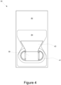
- FIG 4 is a section view of the hydraulic fuse 30 through the plane marked A-A in Figure 2 .
- the first fuse element 39 comprises a retention feature 43 which is configured to retain the first fuse element 39 within the plenum 34.
- the retention feature 43 comprises a first dovetail-shaped portion 43 which is integrally formed with the portion of the first fuse element 39 which is arranged to close the inlet 35.
- the width of the first dovetail-shaped portion 43 is greater than the width of the inlet 35.
- the second fuse element 40 also comprises a retention feature 44 which is configured to retain the second fuse element 40 within the plenum 34.
- the retention feature 44 comprises a second dovetail-shaped portion 44 which is integrally formed with the portion of the second fuse element 40 which is arranged to close the outlet 36.
- the width of the second dovetail-shaped portion 44 is greater than the width of the outlet 36.
- the retention feature 43, 44 may be any feature which enables the first fuse element 39 and the second fuse element 40 to be retained within the plenum 34 when the first fuse element 39 and the second fuse element 40 are broken.
- the retention feature may comprise a flexible member which enables the first fuse element 39 and the second fuse element to remain attached to the fuse body 32 even when the first fuse element 39 and the second fuse element 40 are broken.
- the retention feature may comprise a connecting member between the first fuse element 39 and the second fuse element 40 which connects the first fuse element 39 and the second fuse element 40 together.
- the hydraulic fuse 30 may be formed from an additive manufacturing process.
- the additive manufacturing process may be used to integrally form the fuse body 32, the first fuse element 39, and the second fuse element 40.
- the additive manufacturing process may include a powder bed process, a material deposition process, or a 3D printing process.
- the powder bed process may be a laser powder bed process.
- the hydraulic fuse 30 may be formed from a casting process.
- the hydraulic fuse 30 may be formed from any material suitable for the desired use.
- the hydraulic fuse 30 may be formed from a metal.
- the hydraulic fuse 30 is arranged between the first fluid location 37 and the second fluid location 38.
- the inlet 36 is coupled to the first fluid location 37 and the outlet is coupled to the second fluid location 38.
- the first fluid location 37 will be at a higher fluid pressure than the second fluid location 38.
- the hydraulic fuse 30 is in an inactive state, as shown in Figure 2 . Fluid at the first fluid location 37 will flow past the first substantially continuous surface 45 of the hydraulic fuse 30 and fluid at the second fluid location 38 will flow past the second substantially continuous surface 46 of the hydraulic fuse 30.
- the first fuse element 39 closes the inlet 35 and the second fuse element 40 closes the outlet 36, which prevents fluid flow into and through the plenum 34.
- the fluid pressure in the plenum 34 may be at atmospheric pressure. During a fluid overpressure event, such as a blockage in one of the fluid locations, the pressure in the fluid locations may increase.
- the hydraulic fuse 30 is caused to move to an active state when the pressure differential between the first fluid location 37 and the plenum 34 reaches the first threshold.
- the first fuse element 39 is configured to break at the first thin wall section 41 and open the inlet 35. Fluid from the first fluid location is consequently permitted to flow into the plenum 34.
- the retention feature 43 of the first fuse element 39 retains the first fuse element within the plenum 34.
- the plenum 34 now has a higher fluid pressure than in the inactive state due to the presence of the fluid from the first fluid location 37.
- the second fuse element 40 is configured to break at the second thin wall section 42 and open the outlet 36. Fluid is then permitted to flow from the plenum 34 to the second fluid location 38 through the outlet 36. The overpressure event is thereby relieved by permitting fluid to flow from the first fluid location 37 to the second fluid location 38 via the hydraulic fuse 30.
- FIG. 5 shows a first example of a hydraulic manifold 50 according to the present disclosure.
- the hydraulic manifold 50 comprises a first fluid conduit 65 and a second fluid conduit 66.
- the first fluid conduit 65 and the second fluid conduit 66 are divided or separated by a manifold wall 52.
- the first fluid conduit 65 defines a first fluid location 57 and the second fluid conduit 58 defines a second fluid location 58.
- the first fluid conduit 65 is larger than the second fluid conduit 66.
- the first fluid conduit 65 is configured to carry fluid at a higher pressure than the second fluid conduit 66.
- the hydraulic manifold 50 also comprises a hydraulic fuse 69.
- the hydraulic fuse 69 is disposed in the manifold wall 52.
- the hydraulic fuse 69 is integrally formed with the manifold wall 52 such that a fuse body of the hydraulic fuse 69 is formed by the manifold wall 52.
- the hydraulic fuse 69 comprises a plenum 54 formed in the manifold wall 52, a first fuse element 59, and a second fuse element 60.
- the plenum 54 has an inlet 55 and an outlet 56.
- the inlet 55 is configured to fluidly couple to the first fluid location 57 in the first fluid conduit 65.
- the outlet 58 is configured to fluidly couple to the second fluid location 58 in the second fluid conduit 66.
- the first fuse element 59 is arranged to close the inlet 55, such that fluid is prevented from entering the plenum 54 from the first fluid location 57, via the inlet 55.
- the second fuse element 60 is arranged to close the outlet 56, such that fluid is prevented from flowing between the plenum 54 and the second fluid location 58.
- the first fuse element 59 and the second fuse element 60 are integrally formed with the manifold wall 52.
- the first fuse element 59 is formed integrally with a portion of the manifold wall 52 which faces the first fluid location 57
- the second fuse element 60 is formed integrally with a portion of the manifold wall 52 which faces the second fluid location 58.
- the first fuse element 59 and the second fuse element 60 are frangible, i.e., they are configured to be breakable.
- the first fuse element 59 and the second fuse element 60 may be configured to break in a brittle manner by bursting or shattering, or by breaking in a ductile manner by tearing. This may be enabled by varying the materials used for the first and second fuse elements or by varying the structure of the first and second fuse elements.
- the first fuse element 59 has a first thin wall section 61, which forms a first weak point between the first fuse element 59 and the manifold wall 52
- the second fuse element 60 has a second thin wall section 62, which forms a second weak point between the second fuse element 60 and the manifold wall 52.
- the first weak point and the second weak point form predetermined fracture points for the first and second fuse element 59, 60, respectively, such that the first fuse element 59 and the second fuse element 60 are designed to break at the first and second weak points, respectively.
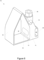
- Figure 6 shows an isometric view of the hydraulic manifold 50.
- the first thin wall section 61 extends around the perimeter of the portion of the first fuse element 59 which is formed as part of the manifold wall 52.
- the second thin wall section 62 extends around the perimeter of the portion of the second fuse element 60 which is formed as part of the manifold wall 52.
- the first thin wall section 61 is configured to break or burst when a fluid pressure differential between the first fluid location 57 and the plenum 54 reaches or exceeds a first threshold pressure.
- the second thin wall section 62 is configured to break or burst when a fluid pressure differential between the plenum 54 and the second fluid location 68 reaches or exceeds a second threshold pressure.
- the first threshold pressure is higher than the second threshold pressure.
- breaking or bursting means that the first thin wall section 61 is broken to at least partially open the inlet 55 and allow fluid to flow from the first fluid location 57 in the first fluid conduit 65 to the plenum 54, and the second thin wall section 62 is broken to at least partially open the outlet 56 and allow fluid to flow from the plenum 54 to the second fluid location 58 in the second fluid conduit 66.
- the first thin wall section 61 and the second thin wall section 62 may be configured by any means to enable it to burst above the first threshold pressure and the second threshold pressure, respectively.
- the thickness of the thin wall sections, the surface area of the thin wall sections, and/or the materials of the thin wall sections may be selected or varied to tune or design the thin wall sections to burst at or above the desired pressure levels.
- the first thin wall section 61 may have a greater thickness than the second thin wall section 62 to enable it to burst at a higher pressure than the second thin wall section 62.
- the first fuse element 59 and the second fuse element 60 are contained within the volume circumscribed by the manifold wall 52. As shown in Figure 6 , the first fuse element 59 and the manifold wall 52 together form a first smooth, substantially continuous surface 51 of the manifold wall 52 which faces the first fluid location 57. Here, the first fuse element 59 is formed integrally with the manifold wall 52 to form the substantially continuous surface 51 which faces the first fluid location 57. Similarly, the second fuse element 60 and the manifold wall 52 together form a second smooth, substantially continuous surface 53 of the manifold wall 52 which faces the second fluid location 58. Here, the second fuse element 60 is formed integrally with the manifold wall 52 to form the substantially continuous surface 53 which faces the first fluid location 58.
- the first and second substantially continuous surfaces 51, 53 form substantially smooth fluid-washed surfaces which are exposed to fluid flow through the first and second fluid conduits 65, 66, respectively.
- the smooth surfaces ensure that there is negligible pressure loss created by the presence of the hydraulic fuse 69 in the hydraulic manifold 50.
- the first fuse element 59 comprises a retention feature 63 which is configured to retain the first fuse element 59 within the plenum 54.
- the retention feature 63 comprises a first dovetail-shaped portion 63 which is integrally formed with the portion of the first fuse element 59 which is arranged to close the inlet 55.
- the width of the first dovetail-shaped portion 63 is greater than the width of the inlet 55.
- the second fuse element 60 also comprises a retention feature 64 which is configured to retain the second fuse element 60 within the plenum 54.
- the retention feature 64 comprises a second dovetail-shaped portion 64 which is integrally formed with the portion of the second fuse element 60 which is arranged to close the outlet 56.
- the width of the second dovetail-shaped portion 64 is greater than the width of the outlet 56.
- the retention feature 63, 64 may be any feature which enables the first fuse element 59 and the second fuse element 60 to be retained within the plenum 54 when the first fuse element 59 and the second fuse element 60 are broken from the manifold wall 52.
- the retention feature may comprise a flexible member which enables the first fuse element 59 and the second fuse element 60 to remain attached to the fuse body 52 even when the first fuse element 59 and the second fuse element 60 are broken from the manifold wall 52.
- the retention feature may comprise a connecting member between the first fuse element 59 and the second fuse element 60 which connects the first fuse element 59 and the second fuse element 60 together.
- the hydraulic manifold 50 may be formed from an additive manufacturing process.
- the additive manufacturing process may be used to integrally form the first fluid conduit 65, the hydraulic fuse 69, and the second fluid conduit 66.
- the additive manufacturing process may include a powder bed process, a material deposition process, or a 3D printing process.
- the powder bed process may be a laser powder bed process.
- the hydraulic manifold 50 may be formed from a casting process.
- the hydraulic manifold 50 may be formed from any material suitable for the desired use.
- the hydraulic manifold 50 may be formed from a metal.
- the hydraulic manifold 50 further comprises an extraction hole 67 disposed in the manifold wall 52.
- the extraction hole 67 is fluidly coupled with the plenum 54 and enables any material which is present in the plenum 54 to be extracted. For example, debris or powder from the manufacturing process may be present in the plenum 54 and will need to be removed before use.
- the extraction hole 67 is sealed by a sealing element 68.
- the sealing element 68 may be a fastener, such as a screw.
- fluid flows through the first fluid conduit 65 and the second fluid conduit 66. Fluid in the first fluid conduit 65 will be at a higher fluid pressure than fluid in the second fluid conduit 66.
- the hydraulic fuse 69 is in an inactive state, as shown in Figure 5 . Fluid in the first fluid conduit 65 will flow past the first substantially continuous surface 51 of the manifold wall 52 and fluid in the second fluid conduit 66 will flow past the second substantially continuous surface 53 of the manifold wall 52.
- the first fuse element 59 closes the inlet 55 and the second fuse element 60 closes the outlet 56, which prevents fluid flow into and through the plenum 54.
- the fluid pressure in the plenum 54 may be at atmospheric pressure.
- the pressure at the first fluid location 57 may increase.
- the hydraulic fuse 69 is caused to move to an active state when the pressure differential between the first fluid location 57 and the plenum 54 reaches the first threshold.
- the first fuse element 57 is configured to break at the first thin wall section 61 and open the inlet 55. Fluid from the first fluid location 57 in the first fluid conduit 65 is consequently permitted to flow into the plenum 54.
- the retention feature 63 of the first fuse element 59 retains the first fuse element 59 within the plenum 54.
- the plenum 54 now has a higher fluid pressure than in the inactive state due to the presence of the fluid from the first fluid location 57.
- the second fuse element 60 is configured to break at the second thin wall section 62 and open the outlet 56.
- the retention feature 64 of the second fuse element 60 retains the second fuse element 60 within the plenum 54. Fluid is then permitted to flow from the plenum 54 to the second fluid location 58 in the second fluid conduit 66 through the outlet 56.
- the overpressure event is thereby relieved by permitting fluid to flow from the first fluid location 57 in the first fluid conduit 65 to the second fluid location 58 in the second fluid conduit 66 via the hydraulic fuse 69.
- FIG 7 shows a second example of a hydraulic manifold 70 according to the present disclosure.
- the second example hydraulic manifold 70 comprises a fluid conduit 72 and a hydraulic fuse 30.
- the hydraulic fuse 30 is substantially similar to the hydraulic fuse 30 described with reference to Figures 2-4 , with like reference numerals denoting like features.
- the fluid conduit 72 carries a flow of a fluid therethrough.
- the fluid conduit 72 comprises a manifold wall 74 which defines a first fluid location 77.
- the hydraulic fuse 30 is attached to the manifold wall 74 such that the inlet 35 of the hydraulic fuse 30 is configured to fluidly couple to the first fluid location 77 in the fluid conduit 72.
- the outlet 36 of the hydraulic fuse 30 is configured to fluidly couple to ambient conditions, for example to an environment around the hydraulic manifold 70. The ambient conditions therefore form the second fluid location 78.
- the hydraulic fuse 30 may be attached to the manifold wall 74 using any suitable fasteners. In other examples, the hydraulic fuse 30 may be integrally formed with the manifold wall 74.
- the hydraulic fuse 30 comprises a first fuse element 39 and a second fuse element 40, as described with reference to Figures 2-4 .
- the first fuse element 39 is arranged to close the inlet 35, such that fluid is prevented from entering the plenum 34 from the first fluid location 77 in the fluid conduit 72, via the inlet 35.
- the second fuse element 40 is arranged to close the outlet 36, such that fluid is prevented from flowing between the plenum 34 and the second fluid location 78.
- the first fuse element 39 and the second fuse element 40 are integrally formed with the fuse body 32.
- the first fuse element 39 is formed integrally with a wall of the fuse body 32 which faces the first fluid location 77
- the second fuse element 40 is formed integrally with a wall of the fuse body 32 which faces the second fluid location 78.
- the first and second fuse elements 39, 40 are frangible, as described previously.
- the first fuse element 39 and the fuse body 32 together form a first smooth, substantially continuous surface 45 of the fuse body 32 which faces the first fluid location 77.
- the first fuse element 39 is formed integrally with the fuse body 32 to form the substantially continuous surface 45 which faces the first fluid location 77.
- the second fuse element 40 and the fuse body 32 together form a second smooth, substantially continuous surface 46 of the fuse body 32 which faces the second fluid location 78.
- the second fuse element 40 is formed integrally with the fuse body 32 to form the substantially continuous surface 46 which faces the first fluid location 78.
- the substantially continuous surfaces 45, 46 form substantially smooth fluid-washed surfaces which are exposed to fluid flow.
- the hydraulic fuse 30 In normal operation, the hydraulic fuse 30 is in an inactive state, as shown in Figure 7 . Fluid flows through the fluid conduit 72 and past the first substantially continuous surface 45 of the hydraulic fuse 30. In the inactive state, the first fuse element 39 closes the inlet 35 and the second fuse element 40 closes the outlet 36, which prevents fluid flow into and through the plenum 34.
- the fluid pressure in the plenum 34 may be at atmospheric pressure.
- a fluid overpressure event such as a blockage in the fluid conduit 72
- the pressure in the first fluid location 77 may increase.
- the hydraulic fuse 30 is caused to move to an active state when the pressure differential between the first fluid location 77 and the plenum 34 reaches the first threshold.
- the first fuse element 39 When the pressure differential between the first fluid location 77 and the plenum 34 reaches the first threshold, the first fuse element 39 is configured to break at the first thin wall section 41 and open the inlet 35. Fluid from the first fluid location 77 is consequently permitted to flow into the plenum 34. The retention feature 43 of the first fuse element 43 retains the first fuse element within the plenum 34. The plenum 34 now has a higher fluid pressure than in the inactive state due to the presence of the fluid from the first fluid location 77. When the pressure differential between the plenum 34 and the second fluid location 78 reaches the second threshold, the second fuse element 40 is configured to break at the second thin wall section 42 and open the outlet 36. The second threshold will be quickly reached as the second fluid location 88 is at atmospheric pressure.
- the second fuse element 40 will be broken soon after the first fuse element 39 is broken. Fluid is then permitted to flow from the plenum 34 to the second fluid location 78 through the outlet 36, with the second fluid location 78 being in the ambient surroundings. The overpressure event is thereby relieved by permitting fluid to flow from the first fluid location 37 to the second fluid location 78 via the hydraulic fuse 30.
- the hydraulic fuse 30 therefore functions as a pressure relief device which vents to atmospheric pressure in the case of an overpressure event or a pressure surge in the fluid conduit 72.
- Figure 8 shows a third example of a hydraulic manifold according to the present disclosure.
- the third example hydraulic manifold is substantially similar to the first example hydraulic manifold described with reference to Figures 5-6 , with like reference numerals denoting like features.
- the third example hydraulic manifold differs with respect to the first and second fuse elements.
- the hydraulic manifold 90 comprises a first fluid conduit 65 and a second fluid conduit 66.
- the first fluid conduit 65 and the second fluid conduit 66 are divided or separated by a manifold wall 92.
- the first fluid conduit 65 defines a first fluid location 57 and the second fluid conduit 58 defines a second fluid location 58.
- the first fluid conduit 65 is larger than the second fluid conduit 66.
- the first fluid conduit 65 is configured to carry fluid at a higher pressure than the second fluid conduit 66.
- the hydraulic manifold 50 also comprises a hydraulic fuse 109.
- the hydraulic fuse 109 is disposed in the manifold wall 92.
- the hydraulic fuse 109 is integrally formed with the manifold wall 92 such that a fuse body of the hydraulic fuse 109 is formed by the manifold wall 92.
- the hydraulic fuse 109 comprises a plenum 94 formed in the manifold wall 92, a first fuse element 99, and a second fuse element 100.
- the plenum 94 has an inlet 95 and an outlet 96.
- the inlet 95 is configured to fluidly couple to the first fluid location 57 in the first fluid conduit 65.
- the outlet 96 is configured to fluidly couple to the second fluid location 58 in the second fluid conduit 66.
- the first fuse element 99 is arranged to close the inlet 95, such that fluid is prevented from entering the plenum 94 from the first fluid location 57, via the inlet 95.
- the second fuse element 100 is arranged to close the outlet 96, such that fluid is prevented from flowing between the plenum 94 and the second fluid location 58.
- the first fuse element 99 and the second fuse element 100 are integrally formed with the manifold wall 92.
- the first fuse element 99 is formed integrally with a portion of the manifold wall 92 which faces the first fluid location 57
- the second fuse element 100 is formed integrally with a portion of the manifold wall 92 which faces the second fluid location 58.
- the first fuse element 99 and the second fuse element 100 are configured to fracture away from the manifold wall 92.
- the first fuse element 99 and the second fuse element 100 are configured to tear away from the manifold wall 99.
- the thickness of the first fuse element 99 is tapered to a thinnest point at a bottom edge 101 of the first fuse element 99.
- the thickness of the second fuse element 100 is tapered to a thinnest point at a bottom edge 103 of the second fuse element 100.
- the bottom edge 101 of the first fuse element 99 forms a first weak point between the first fuse element 99 and the manifold wall 92
- the bottom edge 103 of the second fuse element 100 forms a second weak point between the second fuse element 100 and the manifold wall 92.
- the first weak point and the second weak point form predetermined fracture points for the first and second fuse element 99, 100, respectively, such that the first fuse element 99 and the second fuse element 100 are designed to fracture at the first and second weak points, respectively.
- the bottom edge 101 of the first fuse element 99 is configured to fracture when a fluid pressure differential between the first fluid location 57 and the plenum 94 reaches a first threshold pressure.
- the bottom edge 103 of the second fuse element 100 is configured to fracture when a fluid pressure differential between the plenum 94 and the second fluid location 58 reaches a second threshold pressure.
- the first threshold pressure is higher than the second threshold pressure.
- the first fuse element 99 and the second fuse element 100 are formed from ductile materials, such as aluminium, such that the first fuse element 99 is configured to fracture at its bottom edge 101 in a ductile manner, and the second fuse element 100 is configured to fracture at its bottom edge 103 in a ductile manner.
- first fuse element 99 is configured to tear at its bottom edge 101 when the fluid pressure differential between the first fluid location 57 and the plenum 94 reaches the first threshold pressure, thus at least partially opening the inlet 95 and allowing fluid to flow from the first fluid location 57 to the plenum 94.
- the second fuse element 100 is also configured to tear at its bottom edge 103 when the fluid pressure differential between the plenum 94 and the second fluid location 58 reaches the second threshold pressure, thus at least partially opening the outlet 96 and allowing fluid to flow from the plenum 94 to the second fluid location 58.
- the thickness of the manifold wall at the bottom edges, the length of the bottom edges, the surface area of the fuse elements, and/or the materials of the fuse elements may be selected or varied to tune or design the bottom edges to fracture at or above the desired pressure thresholds.
- the bottom edge 101 of the first fuse element 99 may have a greater thickness than the bottom edge 103 of the second fuse element 100 to enable it to fracture at a higher pressure than the bottom edge 101 of the first fuse element 99.
- the first weak point and the second weak point may be formed by other edges or points of the first fuse element and the second fuse element, respectively.
- the first fuse element 99 and the second fuse element 100 are contained within the volume circumscribed by the manifold wall 92.
- the first fuse element 99 and the manifold wall 92 together form a first smooth, substantially continuous surface 91 of the manifold wall 92 which faces the first fluid location 57.
- the first fuse element 99 is formed integrally with the manifold wall 92 to form the substantially continuous surface 91 which faces the first fluid location 57.
- the second fuse element 100 and the manifold wall 92 together form a second smooth, substantially continuous surface 93 of the manifold wall 92 which faces the second fluid location 58.
- the second fuse element 100 is formed integrally with the manifold wall 92 to form the substantially continuous surface 93 which faces the first fluid location 58.
- the first and second substantially continuous surfaces 91, 93 form substantially smooth fluid-washed surfaces which are exposed to fluid flow through the first and second fluid conduits 65, 66, respectively.
- the smooth surfaces ensure that there is negligible pressure loss created by the presence of the hydraulic fuse 109 in the hydraulic manifold 90.
- the first fuse element 99 comprises a retention feature 102 which is configured to retain the first fuse element 99 within the plenum 94.
- the retention feature 102 comprises a first series of ridges 102 which are integrally formed on an inner surface of the manifold wall 92 and the first fuse element 99, the inner surface facing the plenum 94.
- Each of the first series of ridges 102 extends substantially vertically across the manifold wall 92 and the first fuse element 99.
- the first series of ridges 102 provide a degree of flexibility to the manifold wall 92 and the first fuse element 99, so that the first fuse element 99 is flexibly attached to the manifold wall 92.
- the first series of ridges 102 therefore enable the manifold wall 92 and the first fuse element 99 to bend together when the bottom edge 101 of the first fuse element 99 is torn. This ensures that the first fuse element 99 remains attached to the manifold wall 92 even when the bottom edge 101 is torn, thereby retaining the first fuse element within the plenum 94 and preventing it from entering the first fluid conduit 65.
- the second fuse element 100 also comprises a retention feature 104 which is configured to retain the second fuse element 100 within the plenum 94.
- the retention feature 104 comprises a second series of ridges 104 which are integrally formed on an inner surface of the manifold wall 92 and the second fuse element 100, the inner surface facing the plenum 94.
- Each of the second series of ridges 104 extends substantially vertically across the manifold wall 92 and the first fuse element 99.
- the second series of ridges 104 provide a degree of flexibility to the manifold wall 92 and the second fuse element 100 so that the second fuse element 100 is flexibly attached to the manifold wall 92.
- the second series of ridges 104 therefore enable the manifold wall 92 and the second fuse element 100 to bend together when the bottom edge 103 of the second fuse element 100 is torn. This ensures that the second fuse element 100 remains attached to the manifold wall 92 even when the bottom edge 103 is torn, thereby retaining the second fuse element within the plenum 94 and preventing it from entering the second fluid conduit 66.
- the retention feature may be any feature which enables the first fuse element 99 and the second fuse element 100 to be retained within the plenum 94 when the first fuse element 99 and the second fuse element 100 are fractured away from the manifold wall 92.
- one of the first fuse element and the second fuse element may be flexibly attached to the manifold wall, as described above, and the other of the first fuse element and the second fuse element may be rigidly attached to or formed with the manifold wall, for example as described with reference to Figures 5-6 .
- the hydraulic manifold 90 may be formed from an additive manufacturing process.
- the additive manufacturing process may be used to integrally form the first fluid conduit 65, the hydraulic fuse 109, and the second fluid conduit 66.
- the additive manufacturing process may include a powder bed process, a material deposition process, or a 3D printing process.
- the powder bed process may be a laser powder bed process.
- the hydraulic manifold 90 may be formed from any material suitable for the desired use.
- the hydraulic manifold 90 may be formed from a ductile material, such as aluminium.
- fluid flows through the first fluid conduit 65 and the second fluid conduit 66. Fluid in the first fluid conduit 65 will be at a higher fluid pressure than fluid in the second fluid conduit 66.
- the hydraulic fuse 109 is in an inactive state, as shown in Figure 8 . Fluid in the first fluid conduit 65 will flow past the first substantially continuous surface 91 of the manifold wall 92 and fluid in the second fluid conduit 66 will flow past the second substantially continuous surface 93 of the manifold wall 92.
- the first fuse element 99 closes the inlet 95 and the second fuse element 100 closes the outlet 96, which prevents fluid flow into and through the plenum 94.
- the fluid pressure in the plenum 94 may be at atmospheric pressure.
- the pressure at the first fluid location 57 may increase.
- the hydraulic fuse 109 is caused to move to an active state when the pressure differential between the first fluid location 57 and the plenum 94 reaches the first threshold.
- the first fuse element 99 is configured to tear at its bottom edge 101 and open the inlet 95. Fluid from the first fluid location 57 in the first fluid conduit 65 is consequently permitted to flow into the plenum 94.
- the retention feature 102 of the first fuse element 99 retains the first fuse element 99 within the plenum 94, as the first fuse element 99 and the manifold wall 92 bend together due to the presence of the ridges 102.
- the plenum 94 now has a higher fluid pressure than in the inactive state due to the presence of the fluid from the first fluid location 57.
- the second fuse element 100 is configured to tear at its bottom edge 103 and open the outlet 96.
- the retention feature 104 of the second fuse element 100 retains the second fuse element 100 within the plenum 94, as the second fuse element 100 and the manifold wall 92 bend together due to the presence of the ridges 104.
- Fluid is then permitted to flow from the plenum 94 to the second fluid location 58 in the second fluid conduit 66 through the outlet 96.
- the overpressure event is thereby relieved by permitting fluid to flow from the first fluid location 57 in the first fluid conduit 65 to the second fluid location 58 in the second fluid conduit 66 via the hydraulic fuse 109.
- the hydraulic fuse and the hydraulic manifold of the present disclosure provide improved reliability of activation of the fuse.
- the first fluid location is isolated from the second fluid location, so that the hydraulic fuse can operate independently of any transient or dynamic pressure differential between the first fluid location and the second fluid location.
- the hydraulic fuse provides a first fuse element between the first fluid location and the plenum and a second fuse element between the plenum and the second fluid location, when enables the hydraulic fuse to be activated when the pressure differential between the first fluid location and the plenum exceeds a designed threshold pressure.
- the activation of the hydraulic fuse is therefore not affected by variations in pressure at the second fluid location relative to the first fluid location.
- the structure of the hydraulic fuse has low complexity and reduced mass compared to known hydraulic fuses.
- the hydraulic fuse can be readily tuned to the desired pressure thresholds required in use, by adapting the first and second fuse elements.
- the hydraulic fuse also presents smooth, continuous surfaces to the fluid flow at the first and second fluid locations, thereby minimising pressure loss due to the presence of the hydraulic fuse in a fluid system or a hydraulic manifold.
- the retention features ensure that the first and second fuse elements are retained within the plenum even after the fuse has been activated, reducing the risk of debris entering other parts of the hydraulic manifold or fluid system and causing blockages.
- the hydraulic fuse and the hydraulic manifold can be manufactured integrally with each other, which enables the hydraulic fuse to be easily embedded within the hydraulic manifold in a simple and compact manner.
- the hydraulic fuse and the hydraulic manifold can be manufactured using an additive manufacturing process, which reduces manufacturing time and enables the hydraulic fuse to be located in optimal locations in the hydraulic manifold.
- first fuse element and the second fuse element are configured to be frangible or breakable
- first fuse element and the second fuse element may be otherwise configured to move to open the inlet and the outlet, respectively, without breaking.
- each of the first and second fuse elements may have respective opening mechanisms that allow the inlet to be opened when the pressure differential between the first fluid location and the plenum exceeds the first threshold and allow the outlet to be opened when the pressure differential between the plenum and the second fluid location exceeds the second threshold.
- one of the first fuse element and the second fuse element may be frangible, and the other of the first fuse element and the second fuse element may not be frangible and may be otherwise configured to open the inlet or the outlet.
- the opening mechanisms may also be reversible, in that the first fuse element may be configured to re-close the inlet when the pressure differential between the first fluid location and the plenum falls below the first threshold and that the second fuse element may be configured to re-close the outlet when the pressure differential between the plenum and the second fluid location falls below the second threshold.
- the hydraulic fuse may be reusable.
- first and second fuse elements are integrally formed with the fuse body or the manifold wall
- first and second fuse elements may be otherwise arranged with respect to the fuse body or manifold wall.
- first and second fuse elements may be attached to the fuse body or manifold wall.
- first and second fuse elements are configured to fracture at predetermined weak points or predetermined fracture points
- the first and second fuse elements may be configured to fracture at one or more points which are not predetermined.
- the first or second fuse elements may have multiple weak points and the fuse element may fracture at any of these points, without it being predetermined that the fuse element will fracture at a specific one of these points.
Landscapes
- Engineering & Computer Science (AREA)
- General Engineering & Computer Science (AREA)
- Mechanical Engineering (AREA)
- Fuses (AREA)
- Fluid-Pressure Circuits (AREA)
Abstract
Description
- The present disclosure relates to a hydraulic fuse and a hydraulic manifold.
- A hydraulic manifold or fluidic tube gallery is a component that allows one or more fluids to enter and exit using various machined, cast, or otherwise manufactured fluid conduits. The conduits form a single component which reduces the overall packaging size and complexity when compared to standard pipes or tubes. The hydraulic manifold typically forms part of a fluid system, which can include a pump for driving the fluid through the system. In conventional hydraulic manifolds, in case of an overpressure event, such as that caused by a blocked conduit, the manifold is designed to contain the fluid until another component in the fluid system, such as the pump, fails.
- Overpressure events can also be controlled by other methods, such as by using pressure relief valves or burst disks. Pressure relief valves are designed to open at a predetermined pressure to protect fluid systems from overpressure events. However, pressure relief valves are typically bulky, making them unsuitable for certain types of hydraulic manifolds. They can also suffer from reliability issues and can create areas of pressure loss within the fluid system. Burst disks are designed to rupture at a predetermined pressure differential across the disk to protect fluid systems from overpressure events. However, burst disks are not as effective when there is a transient pressure differential across the disk, and can burst unreliably.
- There is therefore a need to develop a solution to address at least some of the aforementioned problems.
- According to a first aspect of the present disclosure, there is provided a hydraulic fuse comprising: a fuse body defining a plenum, the plenum comprising: an inlet configured to couple to a first fluid location; and an outlet configured to couple to a second fluid location. The hydraulic fuse further comprises a first fuse element arranged to close the inlet, the first fuse element configured to open the inlet when a pressure differential between the first fluid location and the plenum reaches a first threshold; and a second fuse element arranged to close the outlet, the second fuse element configured to open the outlet when a pressure differential between the plenum and the second fluid location reaches a second threshold, wherein the first threshold is higher than the second threshold. In an inactive state, the inlet is closed by the first fuse element and the outlet is closed by the second fuse element to prevent fluid flow through the plenum; and in an active state, the pressure differential between the first fluid location and the plenum reaches the first threshold to cause the first fuse element to open and permit fluid flow through the inlet, and the pressure differential between the plenum and the second fluid location reaches the second threshold to cause the second fuse element to open and permit fluid flow through the outlet.
- The first fuse element may be frangible, such that the first fuse element is configured to fracture and open the inlet when the pressure differential between the first fluid location and the plenum reaches the first threshold. The second fuse element may be frangible, such that the second fuse element is configured to fracture and open the outlet when the pressure differential between the plenum and the second fluid location reaches the second threshold.
- The first fuse element and/or the second fuse element may be configured to fracture at a respective predetermined fracture point.
- The first fuse element and/or the second fuse element may be configured to fracture in a brittle manner.
- The first fuse element and/or the second fuse element may be configured to fracture in a ductile manner.
- The first fuse element and the second fuse element may be integrally formed with the fuse body.
- The first fuse element and the second fuse element may each comprise a respective retention feature configured to retain the first fuse element and the second fuse element within the plenum in the active state.
- The retention feature may be larger than the inlet and outlet.
- The first fuse element and/or the second fuse element may be flexibly attached to the fuse body, such that in the active state, the first fuse element and/or the second fuse element may be configured to bend and remain attached to the fuse body to provide the retention feature.
- The first fuse element and/or the second fuse element may comprise a plurality of ridges formed on a surface facing into the plenum.
- The first fuse element and the second fuse element may be contained within a volume circumscribed by the fuse body.
- In the inactive state, the first fuse element and the fuse body may form a substantially continuous fluid-washed surface facing the first fluid location, and the second fuse element and the fuse body may form a substantially continuous fluid-washed surface facing the second fluid location.
- The hydraulic fuse may be formed by an additive manufacturing process.
- The hydraulic fuse may further comprise: an extraction hole opening into the plenum; and a sealing element configured to close the extraction hole.
- According to a second aspect of the present disclosure, there is provided a hydraulic manifold comprising: a first fluid conduit and a second fluid conduit separated by a manifold wall; and a hydraulic fuse according to the first aspect, wherein the hydraulic fuse is disposed in the manifold wall between the first fluid conduit and the second fluid conduit, such that the first fluid location is in the first fluid conduit and the second fluid location is in the second fluid conduit.
- The hydraulic fuse may be integrally formed with the manifold wall.
- The hydraulic manifold may be formed by an additive manufacturing process.
- According to a third aspect of the present disclosure, there is provided a hydraulic manifold comprising: a fluid conduit defined by a manifold wall; and a hydraulic fuse according to the first aspect; wherein the hydraulic fuse is attached to the manifold wall, such that the first fluid location is in the fluid conduit and the second fluid location is an environment surrounding the hydraulic manifold.
- The hydraulic fuse may be integrally formed with the manifold wall.
- The hydraulic manifold may be formed by an additive manufacturing process.
- Embodiments will now be described by way of example only, with reference to the Figures, in which:
-
Figure 1 is a schematic sectional view of a gas turbine engine; -
Figure 2 is a sectional side view of a first example hydraulic fuse according to the present disclosure; -
Figure 3 is an isometric view of the first example hydraulic fuse as shown inFigure 2 ; -
Figure 4 is a sectional view of the first example hydraulic fuse through the line marked A-A as shown inFigure 2 ; -
Figure 5 is a sectional side view of a first example hydraulic manifold according to the present disclosure; -
Figure 6 is an isometric view of the first example hydraulic manifold as shown inFigure 5 ; -
Figure 7 is a sectional side view of a second example hydraulic manifold according to the present disclosure; and -
Figure 8 is a isometric partial view of a third example hydraulic manifold according to the present disclosure. - With reference to
Figure 1 , a gas turbine engine is generally indicated at 10, having a principal androtational axis 11. Theengine 10 comprises, in axial flow series, anair intake 12, apropulsive fan 13, anintermediate pressure compressor 14, a high-pressure compressor 15,combustion equipment 16, a high-pressure turbine 17, anintermediate pressure turbine 18, a low-pressure turbine 19 and anexhaust nozzle 20. Anacelle 21 generally surrounds theengine 10 and defines both theintake 12 and theexhaust nozzle 20. - The
gas turbine engine 10 works in the conventional manner so that air entering theintake 12 is accelerated by thefan 13 to produce two air flows: a first air flow into theintermediate pressure compressor 14 and a second air flow which passes through a bypass duct 22 to provide propulsive thrust. Theintermediate pressure compressor 14 compresses the air flow directed into it before delivering that air to the high-pressure compressor 15 where further compression takes place. - The compressed air exhausted from the high-
pressure compressor 15 is directed into thecombustion equipment 16 where it is mixed with fuel and the mixture combusted. The resultant hot combustion products then expand through, and thereby drive the high, intermediate and low-pressure turbines nozzle 20 to provide additional propulsive thrust. The high 17, intermediate 18 and low 19 pressure turbines drive respectively the high-pressure compressor 15,intermediate pressure compressor 14 andfan 13, each by suitable interconnecting shaft. - Other gas turbine engines to which the present disclosure may be applied may have alternative configurations. By way of example such engines may have an alternative number of interconnecting shafts (e.g., two) and/or an alternative number of compressors and/or turbines. Further the engine may comprise a gearbox provided in the drive train from a turbine to a compressor and/or fan.
- In fluid systems, such as for fluid systems used in a gas turbine engine, a hydraulic fuse can be used to mitigate fluid overpressure events in the system in case of system failure, for example caused by blockages. A first example of a hydraulic fuse according to the present disclosure is shown in
Figure 2 . Thehydraulic fuse 30 comprises afuse body 32, afirst fuse element 39, and asecond fuse element 40. Thefuse body 32 defines aplenum 34. Theplenum 34 has aninlet 35 and anoutlet 36. Theinlet 35 is configured to fluidly couple to afirst fluid location 37. Theoutlet 38 is configured to fluidly couple to asecond fluid location 38. Thefirst fluid location 37 and thesecond fluid location 38 may be in fluid conduits which are part of the same fluid system or may be coupled to different sources of fluid. Thesecond fluid location 38 may be in ambient conditions, and may, for example, contain or comprise fluid at atmospheric pressure. Thefirst fluid location 37 contains fluid which is at a generally higher fluid pressure than in thesecond fluid location 38. Theplenum 34 may contain fluid at atmospheric pressure. - The
first fuse element 39 is arranged to close theinlet 35, such that fluid is prevented from entering theplenum 34 from thefirst fluid location 37, via theinlet 35. Thesecond fuse element 40 is arranged to close theoutlet 36, such that fluid is prevented from flowing between theplenum 34 and thesecond fluid location 38. Thefirst fuse element 39 and thesecond fuse element 40 are integrally formed with thefuse body 32. In particular, thefirst fuse element 39 is formed integrally with a wall of thefuse body 32 which faces thefirst fluid location 37, and thesecond fuse element 40 is formed integrally with a wall of thefuse body 32 which faces thesecond fluid location 38. - The
first fuse element 39 and thesecond fuse element 40 are frangible, i.e., they are configured to be breakable. Thefirst fuse element 39 and thesecond fuse element 40 may be configured to break in a brittle manner by bursting or shattering, or by breaking in a ductile manner by tearing. This may be enabled by varying the materials used for the first and second fuse elements or by varying the structure of the first and second fuse elements. Thefirst fuse element 39 has a firstthin wall section 41, which forms a first weak point between thefirst fuse element 39 and thefuse body 32, and thesecond fuse element 40 has a secondthin wall section 42, which forms a second weak point between thesecond fuse element 40 and thefuse body 32. The first weak point and the second weak point form predetermined fracture points for the first andsecond fuse element first fuse element 39 and thesecond fuse element 40 are designed to break at the first and second weak points, respectively.Figure 3 shows an isometric view of thehydraulic fuse 30, showing aside 45 of thehydraulic fuse 30 which faces thefirst fluid location 37. The firstthin wall section 41 extends around the perimeter of the portion of thefirst fuse element 39 which is formed as part of the wall of thefuse body 32. In addition, the secondthin wall section 42 extends around the perimeter of the portion of thesecond fuse element 40 which is formed as part of the wall of thefuse body 32. The firstthin wall section 41 is configured to break or burst when a fluid pressure differential between thefirst fluid location 37 and theplenum 34 reaches or exceeds a first threshold pressure. The secondthin wall section 42 is configured to break or burst when a fluid pressure differential between theplenum 34 and thesecond fluid location 38 reaches or exceeds a second threshold pressure. The first threshold pressure is higher than the second threshold pressure. In this context, breaking or bursting means that the firstthin wall section 41 is broken to at least partially open theinlet 35 and allow fluid to flow from thefirst fluid location 37 to theplenum 34, and the secondthin wall section 42 is broken to at least partially open theoutlet 36 and allow fluid to flow from theplenum 34 to thesecond fluid location 38. The firstthin wall section 41 and the secondthin wall section 42 may be configured by any means to enable it to burst at or above the first threshold pressure and the second threshold pressure, respectively. For example, the thickness of the thin wall sections, the surface area of the thin wall sections, and/or the materials of the thin wall sections may be selected or varied to tune or design the thin wall sections to burst at or above the desired pressure thresholds. For example, the firstthin wall section 41 may have a greater thickness than the secondthin wall section 42 to enable it to burst at a higher pressure than the secondthin wall section 42. - The
first fuse element 39 and thesecond fuse element 40 are contained within the volume defined by thefuse body 32. As shown inFigure 3 , thefirst fuse element 39 and thefuse body 32 together form a first smooth, substantiallycontinuous surface 45 of thefuse body 32 which faces thefirst fluid location 37. Here, thefirst fuse element 39 is formed integrally with thefuse body 32 to form the substantiallycontinuous surface 45 which faces thefirst fluid location 37. Similarly, thesecond fuse element 40 and thefuse body 32 together form a second smooth, substantiallycontinuous surface 46 of thefuse body 32 which faces thesecond fluid location 38. Here, thesecond fuse element 40 is formed integrally with thefuse body 32 to form the substantiallycontinuous surface 46 which faces thefirst fluid location 38. The substantiallycontinuous surfaces hydraulic fuse 30 when it is used in a fluid system. -
Figure 4 is a section view of thehydraulic fuse 30 through the plane marked A-A inFigure 2 . Thefirst fuse element 39 comprises aretention feature 43 which is configured to retain thefirst fuse element 39 within theplenum 34. Theretention feature 43 comprises a first dovetail-shapedportion 43 which is integrally formed with the portion of thefirst fuse element 39 which is arranged to close theinlet 35. The width of the first dovetail-shapedportion 43 is greater than the width of theinlet 35. After thefirst fuse element 39 is broken off thefuse body 32 when the firstthin wall section 41 is broken, the first dovetail-shapedportion 43 prevents thefirst fuse element 39 from leaving theplenum 34 via theinlet 35, thereby retaining thefirst fuse element 39 within theplenum 34. Similarly, thesecond fuse element 40 also comprises aretention feature 44 which is configured to retain thesecond fuse element 40 within theplenum 34. Theretention feature 44 comprises a second dovetail-shapedportion 44 which is integrally formed with the portion of thesecond fuse element 40 which is arranged to close theoutlet 36. The width of the second dovetail-shapedportion 44 is greater than the width of theoutlet 36. After thesecond fuse element 40 is broken off thefuse body 32 when the secondthin wall section 42 is broken, the second dovetail-shapedportion 44 prevents thesecond fuse element 40 from leaving theplenum 34 via theoutlet 36, thereby retaining thesecond fuse element 40 within theplenum 34. In other examples, theretention feature first fuse element 39 and thesecond fuse element 40 to be retained within theplenum 34 when thefirst fuse element 39 and thesecond fuse element 40 are broken. For example, the retention feature may comprise a flexible member which enables thefirst fuse element 39 and the second fuse element to remain attached to thefuse body 32 even when thefirst fuse element 39 and thesecond fuse element 40 are broken. In other examples, the retention feature may comprise a connecting member between thefirst fuse element 39 and thesecond fuse element 40 which connects thefirst fuse element 39 and thesecond fuse element 40 together. - The
hydraulic fuse 30 may be formed from an additive manufacturing process. The additive manufacturing process may be used to integrally form thefuse body 32, thefirst fuse element 39, and thesecond fuse element 40. The additive manufacturing process may include a powder bed process, a material deposition process, or a 3D printing process. For example, the powder bed process may be a laser powder bed process. Alternatively, thehydraulic fuse 30 may be formed from a casting process. Thehydraulic fuse 30 may be formed from any material suitable for the desired use. For example, thehydraulic fuse 30 may be formed from a metal. - In use, the
hydraulic fuse 30 is arranged between thefirst fluid location 37 and thesecond fluid location 38. In particular, theinlet 36 is coupled to thefirst fluid location 37 and the outlet is coupled to thesecond fluid location 38. Generally, thefirst fluid location 37 will be at a higher fluid pressure than thesecond fluid location 38. In normal operation, thehydraulic fuse 30 is in an inactive state, as shown inFigure 2 . Fluid at thefirst fluid location 37 will flow past the first substantiallycontinuous surface 45 of thehydraulic fuse 30 and fluid at thesecond fluid location 38 will flow past the second substantiallycontinuous surface 46 of thehydraulic fuse 30. In the inactive state, thefirst fuse element 39 closes theinlet 35 and thesecond fuse element 40 closes theoutlet 36, which prevents fluid flow into and through theplenum 34. The fluid pressure in theplenum 34 may be at atmospheric pressure. During a fluid overpressure event, such as a blockage in one of the fluid locations, the pressure in the fluid locations may increase. Thehydraulic fuse 30 is caused to move to an active state when the pressure differential between thefirst fluid location 37 and theplenum 34 reaches the first threshold. When the pressure differential between thefirst fluid location 37 and theplenum 34 reaches the first threshold, thefirst fuse element 39 is configured to break at the firstthin wall section 41 and open theinlet 35. Fluid from the first fluid location is consequently permitted to flow into theplenum 34. Theretention feature 43 of thefirst fuse element 39 retains the first fuse element within theplenum 34. Theplenum 34 now has a higher fluid pressure than in the inactive state due to the presence of the fluid from thefirst fluid location 37. When the pressure differential between theplenum 34 and thesecond fluid location 38 reaches the second threshold, thesecond fuse element 40 is configured to break at the secondthin wall section 42 and open theoutlet 36. Fluid is then permitted to flow from theplenum 34 to thesecond fluid location 38 through theoutlet 36. The overpressure event is thereby relieved by permitting fluid to flow from thefirst fluid location 37 to thesecond fluid location 38 via thehydraulic fuse 30. -
Figure 5 shows a first example of ahydraulic manifold 50 according to the present disclosure. Thehydraulic manifold 50 comprises a firstfluid conduit 65 and a secondfluid conduit 66. The firstfluid conduit 65 and the secondfluid conduit 66 are divided or separated by amanifold wall 52. The firstfluid conduit 65 defines afirst fluid location 57 and the secondfluid conduit 58 defines asecond fluid location 58. The firstfluid conduit 65 is larger than the secondfluid conduit 66. The firstfluid conduit 65 is configured to carry fluid at a higher pressure than the secondfluid conduit 66. Thehydraulic manifold 50 also comprises ahydraulic fuse 69. Thehydraulic fuse 69 is disposed in themanifold wall 52. In particular, thehydraulic fuse 69 is integrally formed with themanifold wall 52 such that a fuse body of thehydraulic fuse 69 is formed by themanifold wall 52. Thehydraulic fuse 69 comprises aplenum 54 formed in themanifold wall 52, afirst fuse element 59, and asecond fuse element 60. Theplenum 54 has aninlet 55 and anoutlet 56. Theinlet 55 is configured to fluidly couple to thefirst fluid location 57 in the firstfluid conduit 65. Theoutlet 58 is configured to fluidly couple to thesecond fluid location 58 in the secondfluid conduit 66. - The
first fuse element 59 is arranged to close theinlet 55, such that fluid is prevented from entering theplenum 54 from thefirst fluid location 57, via theinlet 55. Thesecond fuse element 60 is arranged to close theoutlet 56, such that fluid is prevented from flowing between theplenum 54 and thesecond fluid location 58. Thefirst fuse element 59 and thesecond fuse element 60 are integrally formed with themanifold wall 52. In particular, thefirst fuse element 59 is formed integrally with a portion of themanifold wall 52 which faces thefirst fluid location 57, and thesecond fuse element 60 is formed integrally with a portion of themanifold wall 52 which faces thesecond fluid location 58. - The
first fuse element 59 and thesecond fuse element 60 are frangible, i.e., they are configured to be breakable. Thefirst fuse element 59 and thesecond fuse element 60 may be configured to break in a brittle manner by bursting or shattering, or by breaking in a ductile manner by tearing. This may be enabled by varying the materials used for the first and second fuse elements or by varying the structure of the first and second fuse elements. Thefirst fuse element 59 has a firstthin wall section 61, which forms a first weak point between thefirst fuse element 59 and themanifold wall 52, and thesecond fuse element 60 has a secondthin wall section 62, which forms a second weak point between thesecond fuse element 60 and themanifold wall 52. The first weak point and the second weak point form predetermined fracture points for the first andsecond fuse element first fuse element 59 and thesecond fuse element 60 are designed to break at the first and second weak points, respectively. -
Figure 6 shows an isometric view of thehydraulic manifold 50. The firstthin wall section 61 extends around the perimeter of the portion of thefirst fuse element 59 which is formed as part of themanifold wall 52. Similarly, the secondthin wall section 62 extends around the perimeter of the portion of thesecond fuse element 60 which is formed as part of themanifold wall 52. The firstthin wall section 61 is configured to break or burst when a fluid pressure differential between thefirst fluid location 57 and theplenum 54 reaches or exceeds a first threshold pressure. The secondthin wall section 62 is configured to break or burst when a fluid pressure differential between theplenum 54 and thesecond fluid location 68 reaches or exceeds a second threshold pressure. The first threshold pressure is higher than the second threshold pressure. In this context, breaking or bursting means that the firstthin wall section 61 is broken to at least partially open theinlet 55 and allow fluid to flow from thefirst fluid location 57 in the firstfluid conduit 65 to theplenum 54, and the secondthin wall section 62 is broken to at least partially open theoutlet 56 and allow fluid to flow from theplenum 54 to thesecond fluid location 58 in the secondfluid conduit 66. The firstthin wall section 61 and the secondthin wall section 62 may be configured by any means to enable it to burst above the first threshold pressure and the second threshold pressure, respectively. For example, the thickness of the thin wall sections, the surface area of the thin wall sections, and/or the materials of the thin wall sections may be selected or varied to tune or design the thin wall sections to burst at or above the desired pressure levels. For example, the firstthin wall section 61 may have a greater thickness than the secondthin wall section 62 to enable it to burst at a higher pressure than the secondthin wall section 62. - The
first fuse element 59 and thesecond fuse element 60 are contained within the volume circumscribed by themanifold wall 52. As shown inFigure 6 , thefirst fuse element 59 and themanifold wall 52 together form a first smooth, substantiallycontinuous surface 51 of themanifold wall 52 which faces thefirst fluid location 57. Here, thefirst fuse element 59 is formed integrally with themanifold wall 52 to form the substantiallycontinuous surface 51 which faces thefirst fluid location 57. Similarly, thesecond fuse element 60 and themanifold wall 52 together form a second smooth, substantiallycontinuous surface 53 of themanifold wall 52 which faces thesecond fluid location 58. Here, thesecond fuse element 60 is formed integrally with themanifold wall 52 to form the substantiallycontinuous surface 53 which faces thefirst fluid location 58. The first and second substantiallycontinuous surfaces fluid conduits hydraulic fuse 69 in thehydraulic manifold 50. - The
first fuse element 59 comprises aretention feature 63 which is configured to retain thefirst fuse element 59 within theplenum 54. Theretention feature 63 comprises a first dovetail-shapedportion 63 which is integrally formed with the portion of thefirst fuse element 59 which is arranged to close theinlet 55. The width of the first dovetail-shapedportion 63 is greater than the width of theinlet 55. After thefirst fuse element 59 is broken off themanifold wall 52 when the firstthin wall section 61 is broken, the first dovetail-shapedportion 63 prevents thefirst fuse element 59 from leaving theplenum 54 via theinlet 55, thereby retaining thefirst fuse element 59 within theplenum 54. - Similarly, the
second fuse element 60 also comprises aretention feature 64 which is configured to retain thesecond fuse element 60 within theplenum 54. Theretention feature 64 comprises a second dovetail-shapedportion 64 which is integrally formed with the portion of thesecond fuse element 60 which is arranged to close theoutlet 56. The width of the second dovetail-shapedportion 64 is greater than the width of theoutlet 56. After thesecond fuse element 60 is broken off themanifold wall 52 when the secondthin wall section 62 is broken, the second dovetail-shapedportion 64 prevents thesecond fuse element 60 from leaving theplenum 54 via theoutlet 56, thereby retaining thesecond fuse element 60 within theplenum 54. In other examples, theretention feature first fuse element 59 and thesecond fuse element 60 to be retained within theplenum 54 when thefirst fuse element 59 and thesecond fuse element 60 are broken from themanifold wall 52. For example, the retention feature may comprise a flexible member which enables thefirst fuse element 59 and thesecond fuse element 60 to remain attached to thefuse body 52 even when thefirst fuse element 59 and thesecond fuse element 60 are broken from themanifold wall 52. In other examples, the retention feature may comprise a connecting member between thefirst fuse element 59 and thesecond fuse element 60 which connects thefirst fuse element 59 and thesecond fuse element 60 together. - The
hydraulic manifold 50 may be formed from an additive manufacturing process. The additive manufacturing process may be used to integrally form the firstfluid conduit 65, thehydraulic fuse 69, and the secondfluid conduit 66. The additive manufacturing process may include a powder bed process, a material deposition process, or a 3D printing process. For example, the powder bed process may be a laser powder bed process. Alternatively, thehydraulic manifold 50 may be formed from a casting process. Thehydraulic manifold 50 may be formed from any material suitable for the desired use. For example, thehydraulic manifold 50 may be formed from a metal. - The
hydraulic manifold 50 further comprises anextraction hole 67 disposed in themanifold wall 52. Theextraction hole 67 is fluidly coupled with theplenum 54 and enables any material which is present in theplenum 54 to be extracted. For example, debris or powder from the manufacturing process may be present in theplenum 54 and will need to be removed before use. Theextraction hole 67 is sealed by a sealingelement 68. The sealingelement 68 may be a fastener, such as a screw. - In use, fluid flows through the first
fluid conduit 65 and the secondfluid conduit 66. Fluid in the firstfluid conduit 65 will be at a higher fluid pressure than fluid in the secondfluid conduit 66. In normal operation, thehydraulic fuse 69 is in an inactive state, as shown inFigure 5 . Fluid in the firstfluid conduit 65 will flow past the first substantiallycontinuous surface 51 of themanifold wall 52 and fluid in the secondfluid conduit 66 will flow past the second substantiallycontinuous surface 53 of themanifold wall 52. In the inactive state, thefirst fuse element 59 closes theinlet 55 and thesecond fuse element 60 closes theoutlet 56, which prevents fluid flow into and through theplenum 54. The fluid pressure in theplenum 54 may be at atmospheric pressure. During a fluid overpressure event, such as a blockage in the firstfluid conduit 65, the pressure at thefirst fluid location 57 may increase. Thehydraulic fuse 69 is caused to move to an active state when the pressure differential between thefirst fluid location 57 and theplenum 54 reaches the first threshold. When the pressure differential between thefirst fluid location 57 and theplenum 54 reaches the first threshold, thefirst fuse element 57 is configured to break at the firstthin wall section 61 and open theinlet 55. Fluid from thefirst fluid location 57 in the firstfluid conduit 65 is consequently permitted to flow into theplenum 54. Theretention feature 63 of thefirst fuse element 59 retains thefirst fuse element 59 within theplenum 54. Theplenum 54 now has a higher fluid pressure than in the inactive state due to the presence of the fluid from thefirst fluid location 57. When the pressure differential between theplenum 54 and thesecond fluid location 58 reaches the second threshold, thesecond fuse element 60 is configured to break at the secondthin wall section 62 and open theoutlet 56. Theretention feature 64 of thesecond fuse element 60 retains thesecond fuse element 60 within theplenum 54. Fluid is then permitted to flow from theplenum 54 to thesecond fluid location 58 in the secondfluid conduit 66 through theoutlet 56. The overpressure event is thereby relieved by permitting fluid to flow from thefirst fluid location 57 in the firstfluid conduit 65 to thesecond fluid location 58 in the secondfluid conduit 66 via thehydraulic fuse 69. -
Figure 7 shows a second example of ahydraulic manifold 70 according to the present disclosure. The second examplehydraulic manifold 70 comprises afluid conduit 72 and ahydraulic fuse 30. Thehydraulic fuse 30 is substantially similar to thehydraulic fuse 30 described with reference toFigures 2-4 , with like reference numerals denoting like features. - The
fluid conduit 72 carries a flow of a fluid therethrough. Thefluid conduit 72 comprises amanifold wall 74 which defines afirst fluid location 77. Thehydraulic fuse 30 is attached to themanifold wall 74 such that theinlet 35 of thehydraulic fuse 30 is configured to fluidly couple to thefirst fluid location 77 in thefluid conduit 72. Theoutlet 36 of thehydraulic fuse 30 is configured to fluidly couple to ambient conditions, for example to an environment around thehydraulic manifold 70. The ambient conditions therefore form thesecond fluid location 78. Thehydraulic fuse 30 may be attached to themanifold wall 74 using any suitable fasteners. In other examples, thehydraulic fuse 30 may be integrally formed with themanifold wall 74. - The
hydraulic fuse 30 comprises afirst fuse element 39 and asecond fuse element 40, as described with reference toFigures 2-4 . Thefirst fuse element 39 is arranged to close theinlet 35, such that fluid is prevented from entering theplenum 34 from thefirst fluid location 77 in thefluid conduit 72, via theinlet 35. Thesecond fuse element 40 is arranged to close theoutlet 36, such that fluid is prevented from flowing between theplenum 34 and thesecond fluid location 78. Thefirst fuse element 39 and thesecond fuse element 40 are integrally formed with thefuse body 32. In particular, thefirst fuse element 39 is formed integrally with a wall of thefuse body 32 which faces thefirst fluid location 77, and thesecond fuse element 40 is formed integrally with a wall of thefuse body 32 which faces thesecond fluid location 78. The first andsecond fuse elements first fuse element 39 and thefuse body 32 together form a first smooth, substantiallycontinuous surface 45 of thefuse body 32 which faces thefirst fluid location 77. Here, thefirst fuse element 39 is formed integrally with thefuse body 32 to form the substantiallycontinuous surface 45 which faces thefirst fluid location 77. Similarly, thesecond fuse element 40 and thefuse body 32 together form a second smooth, substantiallycontinuous surface 46 of thefuse body 32 which faces thesecond fluid location 78. Here, thesecond fuse element 40 is formed integrally with thefuse body 32 to form the substantiallycontinuous surface 46 which faces thefirst fluid location 78. The substantiallycontinuous surfaces - In normal operation, the
hydraulic fuse 30 is in an inactive state, as shown inFigure 7 . Fluid flows through thefluid conduit 72 and past the first substantiallycontinuous surface 45 of thehydraulic fuse 30. In the inactive state, thefirst fuse element 39 closes theinlet 35 and thesecond fuse element 40 closes theoutlet 36, which prevents fluid flow into and through theplenum 34. The fluid pressure in theplenum 34 may be at atmospheric pressure. During a fluid overpressure event, such as a blockage in thefluid conduit 72, the pressure in thefirst fluid location 77 may increase. Thehydraulic fuse 30 is caused to move to an active state when the pressure differential between thefirst fluid location 77 and theplenum 34 reaches the first threshold. When the pressure differential between thefirst fluid location 77 and theplenum 34 reaches the first threshold, thefirst fuse element 39 is configured to break at the firstthin wall section 41 and open theinlet 35. Fluid from thefirst fluid location 77 is consequently permitted to flow into theplenum 34. Theretention feature 43 of thefirst fuse element 43 retains the first fuse element within theplenum 34. Theplenum 34 now has a higher fluid pressure than in the inactive state due to the presence of the fluid from thefirst fluid location 77. When the pressure differential between theplenum 34 and thesecond fluid location 78 reaches the second threshold, thesecond fuse element 40 is configured to break at the secondthin wall section 42 and open theoutlet 36. The second threshold will be quickly reached as the second fluid location 88 is at atmospheric pressure. Therefore, thesecond fuse element 40 will be broken soon after thefirst fuse element 39 is broken. Fluid is then permitted to flow from theplenum 34 to thesecond fluid location 78 through theoutlet 36, with thesecond fluid location 78 being in the ambient surroundings. The overpressure event is thereby relieved by permitting fluid to flow from thefirst fluid location 37 to thesecond fluid location 78 via thehydraulic fuse 30. Thehydraulic fuse 30 therefore functions as a pressure relief device which vents to atmospheric pressure in the case of an overpressure event or a pressure surge in thefluid conduit 72. -
Figure 8 shows a third example of a hydraulic manifold according to the present disclosure. The third example hydraulic manifold is substantially similar to the first example hydraulic manifold described with reference toFigures 5-6 , with like reference numerals denoting like features. The third example hydraulic manifold differs with respect to the first and second fuse elements. - The
hydraulic manifold 90 comprises a firstfluid conduit 65 and a secondfluid conduit 66. The firstfluid conduit 65 and the secondfluid conduit 66 are divided or separated by amanifold wall 92. The firstfluid conduit 65 defines afirst fluid location 57 and the secondfluid conduit 58 defines asecond fluid location 58. The firstfluid conduit 65 is larger than the secondfluid conduit 66. The firstfluid conduit 65 is configured to carry fluid at a higher pressure than the secondfluid conduit 66. Thehydraulic manifold 50 also comprises ahydraulic fuse 109. Thehydraulic fuse 109 is disposed in themanifold wall 92. In particular, thehydraulic fuse 109 is integrally formed with themanifold wall 92 such that a fuse body of thehydraulic fuse 109 is formed by themanifold wall 92. Thehydraulic fuse 109 comprises aplenum 94 formed in themanifold wall 92, afirst fuse element 99, and asecond fuse element 100. Theplenum 94 has aninlet 95 and anoutlet 96. Theinlet 95 is configured to fluidly couple to thefirst fluid location 57 in the firstfluid conduit 65. Theoutlet 96 is configured to fluidly couple to thesecond fluid location 58 in the secondfluid conduit 66. - The
first fuse element 99 is arranged to close theinlet 95, such that fluid is prevented from entering theplenum 94 from thefirst fluid location 57, via theinlet 95. Thesecond fuse element 100 is arranged to close theoutlet 96, such that fluid is prevented from flowing between theplenum 94 and thesecond fluid location 58. Thefirst fuse element 99 and thesecond fuse element 100 are integrally formed with themanifold wall 92. In particular, thefirst fuse element 99 is formed integrally with a portion of themanifold wall 92 which faces thefirst fluid location 57, and thesecond fuse element 100 is formed integrally with a portion of themanifold wall 92 which faces thesecond fluid location 58. - The
first fuse element 99 and thesecond fuse element 100 are configured to fracture away from themanifold wall 92. In particular, thefirst fuse element 99 and thesecond fuse element 100 are configured to tear away from themanifold wall 99. The thickness of thefirst fuse element 99 is tapered to a thinnest point at abottom edge 101 of thefirst fuse element 99. Similarly, the thickness of thesecond fuse element 100 is tapered to a thinnest point at abottom edge 103 of thesecond fuse element 100. By being the thinnest points of themanifold wall 92, thebottom edge 101 of thefirst fuse element 99 forms a first weak point between thefirst fuse element 99 and themanifold wall 92, and thebottom edge 103 of thesecond fuse element 100 forms a second weak point between thesecond fuse element 100 and themanifold wall 92. The first weak point and the second weak point form predetermined fracture points for the first andsecond fuse element first fuse element 99 and thesecond fuse element 100 are designed to fracture at the first and second weak points, respectively. Thebottom edge 101 of thefirst fuse element 99 is configured to fracture when a fluid pressure differential between thefirst fluid location 57 and theplenum 94 reaches a first threshold pressure. Thebottom edge 103 of thesecond fuse element 100 is configured to fracture when a fluid pressure differential between theplenum 94 and thesecond fluid location 58 reaches a second threshold pressure. The first threshold pressure is higher than the second threshold pressure. Thefirst fuse element 99 and thesecond fuse element 100 are formed from ductile materials, such as aluminium, such that thefirst fuse element 99 is configured to fracture at itsbottom edge 101 in a ductile manner, and thesecond fuse element 100 is configured to fracture at itsbottom edge 103 in a ductile manner. This means that thefirst fuse element 99 is configured to tear at itsbottom edge 101 when the fluid pressure differential between thefirst fluid location 57 and theplenum 94 reaches the first threshold pressure, thus at least partially opening theinlet 95 and allowing fluid to flow from thefirst fluid location 57 to theplenum 94. Thesecond fuse element 100 is also configured to tear at itsbottom edge 103 when the fluid pressure differential between theplenum 94 and thesecond fluid location 58 reaches the second threshold pressure, thus at least partially opening theoutlet 96 and allowing fluid to flow from theplenum 94 to thesecond fluid location 58. The thickness of the manifold wall at the bottom edges, the length of the bottom edges, the surface area of the fuse elements, and/or the materials of the fuse elements may be selected or varied to tune or design the bottom edges to fracture at or above the desired pressure thresholds. For example, thebottom edge 101 of thefirst fuse element 99 may have a greater thickness than thebottom edge 103 of thesecond fuse element 100 to enable it to fracture at a higher pressure than thebottom edge 101 of thefirst fuse element 99. In other examples, the first weak point and the second weak point may be formed by other edges or points of the first fuse element and the second fuse element, respectively. - The
first fuse element 99 and thesecond fuse element 100 are contained within the volume circumscribed by themanifold wall 92. Thefirst fuse element 99 and themanifold wall 92 together form a first smooth, substantiallycontinuous surface 91 of themanifold wall 92 which faces thefirst fluid location 57. In particular, thefirst fuse element 99 is formed integrally with themanifold wall 92 to form the substantiallycontinuous surface 91 which faces thefirst fluid location 57. Similarly, thesecond fuse element 100 and themanifold wall 92 together form a second smooth, substantiallycontinuous surface 93 of themanifold wall 92 which faces thesecond fluid location 58. Here, thesecond fuse element 100 is formed integrally with themanifold wall 92 to form the substantiallycontinuous surface 93 which faces thefirst fluid location 58. The first and second substantiallycontinuous surfaces fluid conduits hydraulic fuse 109 in thehydraulic manifold 90. - The
first fuse element 99 comprises aretention feature 102 which is configured to retain thefirst fuse element 99 within theplenum 94. Theretention feature 102 comprises a first series ofridges 102 which are integrally formed on an inner surface of themanifold wall 92 and thefirst fuse element 99, the inner surface facing theplenum 94. Each of the first series ofridges 102 extends substantially vertically across themanifold wall 92 and thefirst fuse element 99. The first series ofridges 102 provide a degree of flexibility to themanifold wall 92 and thefirst fuse element 99, so that thefirst fuse element 99 is flexibly attached to themanifold wall 92. The first series ofridges 102 therefore enable themanifold wall 92 and thefirst fuse element 99 to bend together when thebottom edge 101 of thefirst fuse element 99 is torn. This ensures that thefirst fuse element 99 remains attached to themanifold wall 92 even when thebottom edge 101 is torn, thereby retaining the first fuse element within theplenum 94 and preventing it from entering the firstfluid conduit 65. Similarly, thesecond fuse element 100 also comprises aretention feature 104 which is configured to retain thesecond fuse element 100 within theplenum 94. Theretention feature 104 comprises a second series ofridges 104 which are integrally formed on an inner surface of themanifold wall 92 and thesecond fuse element 100, the inner surface facing theplenum 94. Each of the second series ofridges 104 extends substantially vertically across themanifold wall 92 and thefirst fuse element 99. The second series ofridges 104 provide a degree of flexibility to themanifold wall 92 and thesecond fuse element 100 so that thesecond fuse element 100 is flexibly attached to themanifold wall 92. The second series ofridges 104 therefore enable themanifold wall 92 and thesecond fuse element 100 to bend together when thebottom edge 103 of thesecond fuse element 100 is torn. This ensures that thesecond fuse element 100 remains attached to themanifold wall 92 even when thebottom edge 103 is torn, thereby retaining the second fuse element within theplenum 94 and preventing it from entering the secondfluid conduit 66. In other examples, the retention feature may be any feature which enables thefirst fuse element 99 and thesecond fuse element 100 to be retained within theplenum 94 when thefirst fuse element 99 and thesecond fuse element 100 are fractured away from themanifold wall 92. In other examples, one of the first fuse element and the second fuse element may be flexibly attached to the manifold wall, as described above, and the other of the first fuse element and the second fuse element may be rigidly attached to or formed with the manifold wall, for example as described with reference toFigures 5-6 . - The
hydraulic manifold 90 may be formed from an additive manufacturing process. The additive manufacturing process may be used to integrally form the firstfluid conduit 65, thehydraulic fuse 109, and the secondfluid conduit 66. The additive manufacturing process may include a powder bed process, a material deposition process, or a 3D printing process. For example, the powder bed process may be a laser powder bed process. Thehydraulic manifold 90 may be formed from any material suitable for the desired use. For example, thehydraulic manifold 90 may be formed from a ductile material, such as aluminium. - In use, fluid flows through the first
fluid conduit 65 and the secondfluid conduit 66. Fluid in the firstfluid conduit 65 will be at a higher fluid pressure than fluid in the secondfluid conduit 66. In normal operation, thehydraulic fuse 109 is in an inactive state, as shown inFigure 8 . Fluid in the firstfluid conduit 65 will flow past the first substantiallycontinuous surface 91 of themanifold wall 92 and fluid in the secondfluid conduit 66 will flow past the second substantiallycontinuous surface 93 of themanifold wall 92. In the inactive state, thefirst fuse element 99 closes theinlet 95 and thesecond fuse element 100 closes theoutlet 96, which prevents fluid flow into and through theplenum 94. The fluid pressure in theplenum 94 may be at atmospheric pressure. During a fluid overpressure event, such as a blockage in the firstfluid conduit 65, the pressure at thefirst fluid location 57 may increase. Thehydraulic fuse 109 is caused to move to an active state when the pressure differential between thefirst fluid location 57 and theplenum 94 reaches the first threshold. When the pressure differential between thefirst fluid location 57 and theplenum 94 reaches the first threshold, thefirst fuse element 99 is configured to tear at itsbottom edge 101 and open theinlet 95. Fluid from thefirst fluid location 57 in the firstfluid conduit 65 is consequently permitted to flow into theplenum 94. Theretention feature 102 of thefirst fuse element 99 retains thefirst fuse element 99 within theplenum 94, as thefirst fuse element 99 and themanifold wall 92 bend together due to the presence of theridges 102. Theplenum 94 now has a higher fluid pressure than in the inactive state due to the presence of the fluid from thefirst fluid location 57. When the pressure differential between theplenum 94 and thesecond fluid location 58 reaches the second threshold, thesecond fuse element 100 is configured to tear at itsbottom edge 103 and open theoutlet 96. Theretention feature 104 of thesecond fuse element 100 retains thesecond fuse element 100 within theplenum 94, as thesecond fuse element 100 and themanifold wall 92 bend together due to the presence of theridges 104. Fluid is then permitted to flow from theplenum 94 to thesecond fluid location 58 in the secondfluid conduit 66 through theoutlet 96. The overpressure event is thereby relieved by permitting fluid to flow from thefirst fluid location 57 in the firstfluid conduit 65 to thesecond fluid location 58 in the secondfluid conduit 66 via thehydraulic fuse 109. - The hydraulic fuse and the hydraulic manifold of the present disclosure provide improved reliability of activation of the fuse. By having a plenum between the first fluid location and the second fluid location, the first fluid location is isolated from the second fluid location, so that the hydraulic fuse can operate independently of any transient or dynamic pressure differential between the first fluid location and the second fluid location. The hydraulic fuse provides a first fuse element between the first fluid location and the plenum and a second fuse element between the plenum and the second fluid location, when enables the hydraulic fuse to be activated when the pressure differential between the first fluid location and the plenum exceeds a designed threshold pressure. The activation of the hydraulic fuse is therefore not affected by variations in pressure at the second fluid location relative to the first fluid location. This ensures that the hydraulic fuse is able to reliably activate at the designed threshold pressure. The structure of the hydraulic fuse has low complexity and reduced mass compared to known hydraulic fuses. The hydraulic fuse can be readily tuned to the desired pressure thresholds required in use, by adapting the first and second fuse elements. The hydraulic fuse also presents smooth, continuous surfaces to the fluid flow at the first and second fluid locations, thereby minimising pressure loss due to the presence of the hydraulic fuse in a fluid system or a hydraulic manifold. The retention features ensure that the first and second fuse elements are retained within the plenum even after the fuse has been activated, reducing the risk of debris entering other parts of the hydraulic manifold or fluid system and causing blockages. The hydraulic fuse and the hydraulic manifold can be manufactured integrally with each other, which enables the hydraulic fuse to be easily embedded within the hydraulic manifold in a simple and compact manner. The hydraulic fuse and the hydraulic manifold can be manufactured using an additive manufacturing process, which reduces manufacturing time and enables the hydraulic fuse to be located in optimal locations in the hydraulic manifold.
- Although it has been described in the above examples that the first fuse element and the second fuse element are configured to be frangible or breakable, in other examples, the first fuse element and the second fuse element may be otherwise configured to move to open the inlet and the outlet, respectively, without breaking. For example, each of the first and second fuse elements may have respective opening mechanisms that allow the inlet to be opened when the pressure differential between the first fluid location and the plenum exceeds the first threshold and allow the outlet to be opened when the pressure differential between the plenum and the second fluid location exceeds the second threshold. In further examples, one of the first fuse element and the second fuse element may be frangible, and the other of the first fuse element and the second fuse element may not be frangible and may be otherwise configured to open the inlet or the outlet.
- The opening mechanisms may also be reversible, in that the first fuse element may be configured to re-close the inlet when the pressure differential between the first fluid location and the plenum falls below the first threshold and that the second fuse element may be configured to re-close the outlet when the pressure differential between the plenum and the second fluid location falls below the second threshold. In this way, the hydraulic fuse may be reusable.
- Although it has been described in the above examples that the first and second fuse elements are integrally formed with the fuse body or the manifold wall, in other examples, the first and second fuse elements may be otherwise arranged with respect to the fuse body or manifold wall. For example, the first and second fuse elements may be attached to the fuse body or manifold wall.
- Although it has been described in the above examples that the first and second fuse elements are configured to fracture at predetermined weak points or predetermined fracture points, in other examples, the first and second fuse elements may be configured to fracture at one or more points which are not predetermined. For instance, the first or second fuse elements may have multiple weak points and the fuse element may fracture at any of these points, without it being predetermined that the fuse element will fracture at a specific one of these points.
- It will be understood that the disclosure is not limited to the embodiments above-described and various modifications and improvements can be made without departing from the concepts described herein. Except where mutually exclusive, any of the features may be employed separately or in combination with any other features and the disclosure extends to and includes all combinations and sub-combinations of one or more features described herein.
Claims (15)
- A hydraulic fuse comprising:a fuse body defining a plenum, the plenum comprising:an inlet configured to couple to a first fluid location; andan outlet configured to couple to a second fluid location;a first fuse element arranged to close the inlet, the first fuse element configured to open the inlet when a pressure differential between the first fluid location and the plenum reaches a first threshold;a second fuse element arranged to close the outlet, the second fuse element configured to open the outlet when a pressure differential between the plenum and the second fluid location reaches a second threshold, wherein the first threshold is higher than the second threshold;wherein in an inactive state, the inlet is closed by the first fuse element and the outlet is closed by the second fuse element to prevent fluid flow through the plenum; andwherein in an active state, the pressure differential between the first fluid location and the plenum reaches the first threshold to cause the first fuse element to open and permit fluid flow through the inlet, and the pressure differential between the plenum and the second fluid location reaches the second threshold to cause the second fuse element to open and permit fluid flow through the outlet.
- The hydraulic fuse as claimed in Claim 1, wherein the first fuse element is frangible, such that the first fuse element is configured to fracture and open the inlet when the pressure differential between the first fluid location and the plenum reaches the first threshold, and/or the second fuse element is frangible, such that the second fuse element is configured to fracture and open the outlet when the pressure differential between the plenum and the second fluid location reaches the second threshold.
- The hydraulic fuse as claimed in Claim 2, wherein the first fuse element and/or the second fuse element are configured to fracture at a respective predetermined fracture point.
- The hydraulic fuse as claimed in any one of the preceding claims, wherein the first fuse element and the second fuse element are integrally formed with the fuse body.
- The hydraulic fuse as claimed in any one of the preceding claims, wherein the first fuse element and the second fuse element each comprise a respective retention feature configured to retain the first fuse element and the second fuse element within the plenum in the active state.
- The hydraulic fuse as claimed in Claim 5, wherein the retention feature is larger than the inlet and outlet.
- The hydraulic fuse as claimed in Claim 5, wherein the first fuse element and/or the second fuse element are flexibly attached to the fuse body, such that in the active state, the first fuse element and/or the second fuse element are configured to bend and remain attached to the fuse body to provide the retention feature.
- The hydraulic fuse as claimed in Claim 7, wherein the first fuse element and/or the second fuse element comprises a plurality of ridges formed on a surface facing into the plenum.
- The hydraulic fuse as claimed in any one of the preceding claims, wherein the first fuse element and the second fuse element are contained within a volume circumscribed by the fuse body.
- The hydraulic fuse as claimed in any one of the preceding claims, wherein in the inactive state, the first fuse element and the fuse body form a substantially continuous fluid-washed surface facing the first fluid location, and the second fuse element and the fuse body form a substantially continuous fluid-washed surface facing the second fluid location.
- The hydraulic fuse as claimed in any one of the preceding claims, wherein the hydraulic fuse is formed by an additive manufacturing process, and the hydraulic fuse further comprises:an extraction hole opening into the plenum; anda sealing element configured to close the extraction hole.
- A hydraulic manifold comprising:a first fluid conduit and a second fluid conduit separated by a manifold wall; anda hydraulic fuse as claimed in any preceding claim, wherein the hydraulic fuse is disposed in the manifold wall between the first fluid conduit and the second fluid conduit, such that the first fluid location is in the first fluid conduit and the second fluid location is in the second fluid conduit.
- The hydraulic manifold as claimed in Claim 12, wherein the hydraulic fuse is integrally formed with the manifold wall.
- A hydraulic manifold comprising:a fluid conduit defined by a manifold wall; anda hydraulic fuse according to any one of Claims 1 to 11;wherein the hydraulic fuse is attached to the manifold wall, such that the first fluid location is in the fluid conduit and the second fluid location is an environment surrounding the hydraulic manifold.
- The hydraulic manifold as claimed in Claim 14, wherein the hydraulic fuse is integrally formed with the manifold wall.
Applications Claiming Priority (1)
| Application Number | Priority Date | Filing Date | Title |
|---|---|---|---|
| GB202300321 | 2023-01-10 |
Publications (2)
| Publication Number | Publication Date |
|---|---|
| EP4400750A1 true EP4400750A1 (en) | 2024-07-17 |
| EP4400750B1 EP4400750B1 (en) | 2025-08-06 |
Family
ID=89168020
Family Applications (1)
| Application Number | Title | Priority Date | Filing Date |
|---|---|---|---|
| EP23215586.1A Active EP4400750B1 (en) | 2023-01-10 | 2023-12-11 | A hydraulic fuse |
Country Status (2)
| Country | Link |
|---|---|
| US (1) | US12455014B2 (en) |
| EP (1) | EP4400750B1 (en) |
Citations (4)
| Publication number | Priority date | Publication date | Assignee | Title |
|---|---|---|---|---|
| US1584523A (en) * | 1923-05-04 | 1926-05-11 | Charles C Egbert | Pressure-relief device |
| US2387353A (en) * | 1943-05-17 | 1945-10-23 | Raymond Gwynne | Safety device for pressure vessels |
| GB861289A (en) * | 1957-05-22 | 1961-02-15 | Ici Ltd | Improvement in or relating to safety or pressure-relieving devices for pressure vessels |
| JPS5683670A (en) * | 1979-12-10 | 1981-07-08 | Toshiba Corp | Pressure releasing device |
Family Cites Families (12)
| Publication number | Priority date | Publication date | Assignee | Title |
|---|---|---|---|---|
| US1485913A (en) | 1921-02-23 | 1924-03-04 | Gottlieb Carl Julius Alexander | Gas-saving safety device |
| US2661121A (en) * | 1950-08-23 | 1953-12-01 | Black Sivalls & Bryson Inc | Safety pressure device |
| US2788794A (en) | 1954-06-01 | 1957-04-16 | American Cyanamid Co | Gas loaded safety disks |
| US2895492A (en) * | 1955-12-19 | 1959-07-21 | Foster Wheeler Corp | Pressure safety device |
| US3092286A (en) | 1960-11-28 | 1963-06-04 | Duff Philip | Explosive diaphragm valve |
| US3448750A (en) * | 1964-07-20 | 1969-06-10 | Dover Corp W C Norris Division | Method and device for releasing pressure of a pressurized system |
| US4263929A (en) * | 1979-01-08 | 1981-04-28 | Kearney John G | Electropneumatic pressure relief indicator |
| GB2091808A (en) | 1981-01-22 | 1982-08-04 | Bs & B Safety Systems Ltd | Pressure relief apparatus |
| US4951697A (en) | 1989-11-27 | 1990-08-28 | Bs&B Safety Systems, Inc. | Rupture disk failure indicating apparatus |
| GB201303611D0 (en) * | 2013-02-28 | 2013-04-17 | Airbus Operations Ltd | Aircraft fuel tank arrangement |
| FR3099797B1 (en) * | 2019-08-07 | 2021-09-10 | Safran Aircraft Engines | ISOLATION OF A TURBOMACHINE STATOR BLADE HEAT EXCHANGER IN THE EVENT OF A LEAK |
| DE102020207110A1 (en) * | 2020-06-05 | 2021-12-09 | Elringklinger Ag | Rupture device and method for making a burst device |
-
2023
- 2023-12-11 EP EP23215586.1A patent/EP4400750B1/en active Active
- 2023-12-13 US US18/538,259 patent/US12455014B2/en active Active
Patent Citations (4)
| Publication number | Priority date | Publication date | Assignee | Title |
|---|---|---|---|---|
| US1584523A (en) * | 1923-05-04 | 1926-05-11 | Charles C Egbert | Pressure-relief device |
| US2387353A (en) * | 1943-05-17 | 1945-10-23 | Raymond Gwynne | Safety device for pressure vessels |
| GB861289A (en) * | 1957-05-22 | 1961-02-15 | Ici Ltd | Improvement in or relating to safety or pressure-relieving devices for pressure vessels |
| JPS5683670A (en) * | 1979-12-10 | 1981-07-08 | Toshiba Corp | Pressure releasing device |
Also Published As
| Publication number | Publication date |
|---|---|
| EP4400750B1 (en) | 2025-08-06 |
| US12455014B2 (en) | 2025-10-28 |
| US20240229951A1 (en) | 2024-07-11 |
Similar Documents
| Publication | Publication Date | Title |
|---|---|---|
| EP3557028B1 (en) | Gas turbine engine | |
| EP2613035B1 (en) | Environmental control system for aircraft utilizing turbo-compressor | |
| CN108799204B (en) | Centrifugal compressor and supercharger | |
| US11053861B2 (en) | Overspeed protection system and method | |
| US10634060B2 (en) | Engine door with burst seal | |
| KR20030092128A (en) | Burst protection device for radial compressors pertaining to turbochargers | |
| US20070277888A1 (en) | Flow control systems | |
| CA2851466A1 (en) | Turbomachine lubrication system with anti-siphon valve for windmilling | |
| EP2891769A1 (en) | A bleed flow outlet | |
| EP2960468B1 (en) | Geared turbofan engine with low pressure environmental control system for aircraft | |
| US9964114B2 (en) | Flow outlet | |
| EP3163053A1 (en) | Bleed valve arrangement for a gas turbine engine | |
| US12455014B2 (en) | Hydraulic fuse | |
| EP3663566B1 (en) | Passive stability bleed valve with adjustable reference pressure regulator and remote override capability | |
| EP1728992B1 (en) | Bleed valve for a gas turbine engine and a corresponding gas turbine. | |
| US11459955B2 (en) | Fire mitigation system for gas turbine engine | |
| US5063733A (en) | Engine cooling system protection device | |
| EP2966278B1 (en) | Low pressure environmental control system with safe pylon transit | |
| US20110076138A1 (en) | Aspirator Insert for a Boundary Layer in a Fluid, a Wall and a Compressor Equipped with Said Insert | |
| US4713934A (en) | Gas turbine engine air intake | |
| US20190039740A1 (en) | Low pressure environmental control system with safe pylon transit | |
| EP4108896A2 (en) | Air filtration system and method for compressor bleed valve | |
| EP2812548B1 (en) | Gas turbine engine | |
| RU2799266C1 (en) | Method for protecting a gas turbine engine from spinning up a power turbine rotor and a device for its implementation | |
| US7934903B2 (en) | Fluid release valve |
Legal Events
| Date | Code | Title | Description |
|---|---|---|---|
| PUAI | Public reference made under article 153(3) epc to a published international application that has entered the european phase |
Free format text: ORIGINAL CODE: 0009012 |
|
| STAA | Information on the status of an ep patent application or granted ep patent |
Free format text: STATUS: THE APPLICATION HAS BEEN PUBLISHED |
|
| AK | Designated contracting states |
Kind code of ref document: A1 Designated state(s): AL AT BE BG CH CY CZ DE DK EE ES FI FR GB GR HR HU IE IS IT LI LT LU LV MC ME MK MT NL NO PL PT RO RS SE SI SK SM TR |
|
| STAA | Information on the status of an ep patent application or granted ep patent |
Free format text: STATUS: REQUEST FOR EXAMINATION WAS MADE |
|
| 17P | Request for examination filed |
Effective date: 20250116 |
|
| GRAP | Despatch of communication of intention to grant a patent |
Free format text: ORIGINAL CODE: EPIDOSNIGR1 |
|
| STAA | Information on the status of an ep patent application or granted ep patent |
Free format text: STATUS: GRANT OF PATENT IS INTENDED |
|
| INTG | Intention to grant announced |
Effective date: 20250417 |
|
| GRAS | Grant fee paid |
Free format text: ORIGINAL CODE: EPIDOSNIGR3 |
|
| GRAA | (expected) grant |
Free format text: ORIGINAL CODE: 0009210 |
|
| STAA | Information on the status of an ep patent application or granted ep patent |
Free format text: STATUS: THE PATENT HAS BEEN GRANTED |
|
| P01 | Opt-out of the competence of the unified patent court (upc) registered |
Free format text: CASE NUMBER: APP_28694/2025 Effective date: 20250616 |
|
| AK | Designated contracting states |
Kind code of ref document: B1 Designated state(s): AL AT BE BG CH CY CZ DE DK EE ES FI FR GB GR HR HU IE IS IT LI LT LU LV MC ME MK MT NL NO PL PT RO RS SE SI SK SM TR |
|
| REG | Reference to a national code |
Ref country code: GB Ref legal event code: FG4D |
|
| REG | Reference to a national code |
Ref country code: CH Ref legal event code: EP |
|
| REG | Reference to a national code |
Ref country code: DE Ref legal event code: R096 Ref document number: 602023005470 Country of ref document: DE |
|
| REG | Reference to a national code |
Ref country code: IE Ref legal event code: FG4D |
|
| REG | Reference to a national code |
Ref country code: NL Ref legal event code: MP Effective date: 20250806 |
|
| PG25 | Lapsed in a contracting state [announced via postgrant information from national office to epo] |
Ref country code: IS Free format text: LAPSE BECAUSE OF FAILURE TO SUBMIT A TRANSLATION OF THE DESCRIPTION OR TO PAY THE FEE WITHIN THE PRESCRIBED TIME-LIMIT Effective date: 20251206 |
|
| PG25 | Lapsed in a contracting state [announced via postgrant information from national office to epo] |
Ref country code: NO Free format text: LAPSE BECAUSE OF FAILURE TO SUBMIT A TRANSLATION OF THE DESCRIPTION OR TO PAY THE FEE WITHIN THE PRESCRIBED TIME-LIMIT Effective date: 20251106 |
|
| REG | Reference to a national code |
Ref country code: LT Ref legal event code: MG9D |
|
| PG25 | Lapsed in a contracting state [announced via postgrant information from national office to epo] |
Ref country code: PT Free format text: LAPSE BECAUSE OF FAILURE TO SUBMIT A TRANSLATION OF THE DESCRIPTION OR TO PAY THE FEE WITHIN THE PRESCRIBED TIME-LIMIT Effective date: 20251209 |
|
| PG25 | Lapsed in a contracting state [announced via postgrant information from national office to epo] |
Ref country code: FI Free format text: LAPSE BECAUSE OF FAILURE TO SUBMIT A TRANSLATION OF THE DESCRIPTION OR TO PAY THE FEE WITHIN THE PRESCRIBED TIME-LIMIT Effective date: 20250806 |
|
| PG25 | Lapsed in a contracting state [announced via postgrant information from national office to epo] |
Ref country code: HR Free format text: LAPSE BECAUSE OF FAILURE TO SUBMIT A TRANSLATION OF THE DESCRIPTION OR TO PAY THE FEE WITHIN THE PRESCRIBED TIME-LIMIT Effective date: 20250806 Ref country code: NL Free format text: LAPSE BECAUSE OF FAILURE TO SUBMIT A TRANSLATION OF THE DESCRIPTION OR TO PAY THE FEE WITHIN THE PRESCRIBED TIME-LIMIT Effective date: 20250806 |
|
| PGFP | Annual fee paid to national office [announced via postgrant information from national office to epo] |
Ref country code: FR Payment date: 20251230 Year of fee payment: 3 |
|
| PG25 | Lapsed in a contracting state [announced via postgrant information from national office to epo] |
Ref country code: GR Free format text: LAPSE BECAUSE OF FAILURE TO SUBMIT A TRANSLATION OF THE DESCRIPTION OR TO PAY THE FEE WITHIN THE PRESCRIBED TIME-LIMIT Effective date: 20251107 |
|
| PG25 | Lapsed in a contracting state [announced via postgrant information from national office to epo] |
Ref country code: SE Free format text: LAPSE BECAUSE OF FAILURE TO SUBMIT A TRANSLATION OF THE DESCRIPTION OR TO PAY THE FEE WITHIN THE PRESCRIBED TIME-LIMIT Effective date: 20250806 |
|
| PG25 | Lapsed in a contracting state [announced via postgrant information from national office to epo] |
Ref country code: LV Free format text: LAPSE BECAUSE OF FAILURE TO SUBMIT A TRANSLATION OF THE DESCRIPTION OR TO PAY THE FEE WITHIN THE PRESCRIBED TIME-LIMIT Effective date: 20250806 |
|
| PG25 | Lapsed in a contracting state [announced via postgrant information from national office to epo] |
Ref country code: PL Free format text: LAPSE BECAUSE OF FAILURE TO SUBMIT A TRANSLATION OF THE DESCRIPTION OR TO PAY THE FEE WITHIN THE PRESCRIBED TIME-LIMIT Effective date: 20250806 Ref country code: BG Free format text: LAPSE BECAUSE OF FAILURE TO SUBMIT A TRANSLATION OF THE DESCRIPTION OR TO PAY THE FEE WITHIN THE PRESCRIBED TIME-LIMIT Effective date: 20250806 |
|
| PG25 | Lapsed in a contracting state [announced via postgrant information from national office to epo] |
Ref country code: RS Free format text: LAPSE BECAUSE OF FAILURE TO SUBMIT A TRANSLATION OF THE DESCRIPTION OR TO PAY THE FEE WITHIN THE PRESCRIBED TIME-LIMIT Effective date: 20251106 |
|
| PG25 | Lapsed in a contracting state [announced via postgrant information from national office to epo] |
Ref country code: ES Free format text: LAPSE BECAUSE OF FAILURE TO SUBMIT A TRANSLATION OF THE DESCRIPTION OR TO PAY THE FEE WITHIN THE PRESCRIBED TIME-LIMIT Effective date: 20250806 |
|
| REG | Reference to a national code |
Ref country code: AT Ref legal event code: MK05 Ref document number: 1822183 Country of ref document: AT Kind code of ref document: T Effective date: 20250806 |
|
| PG25 | Lapsed in a contracting state [announced via postgrant information from national office to epo] |
Ref country code: RO Free format text: LAPSE BECAUSE OF FAILURE TO SUBMIT A TRANSLATION OF THE DESCRIPTION OR TO PAY THE FEE WITHIN THE PRESCRIBED TIME-LIMIT Effective date: 20250806 |
|
| PG25 | Lapsed in a contracting state [announced via postgrant information from national office to epo] |
Ref country code: SM Free format text: LAPSE BECAUSE OF FAILURE TO SUBMIT A TRANSLATION OF THE DESCRIPTION OR TO PAY THE FEE WITHIN THE PRESCRIBED TIME-LIMIT Effective date: 20250806 |
|
| PG25 | Lapsed in a contracting state [announced via postgrant information from national office to epo] |
Ref country code: DK Free format text: LAPSE BECAUSE OF FAILURE TO SUBMIT A TRANSLATION OF THE DESCRIPTION OR TO PAY THE FEE WITHIN THE PRESCRIBED TIME-LIMIT Effective date: 20250806 |
|
| PGFP | Annual fee paid to national office [announced via postgrant information from national office to epo] |
Ref country code: DE Payment date: 20251229 Year of fee payment: 3 |
|
| PG25 | Lapsed in a contracting state [announced via postgrant information from national office to epo] |
Ref country code: AT Free format text: LAPSE BECAUSE OF FAILURE TO SUBMIT A TRANSLATION OF THE DESCRIPTION OR TO PAY THE FEE WITHIN THE PRESCRIBED TIME-LIMIT Effective date: 20250806 |
|
| PG25 | Lapsed in a contracting state [announced via postgrant information from national office to epo] |
Ref country code: IT Free format text: LAPSE BECAUSE OF FAILURE TO SUBMIT A TRANSLATION OF THE DESCRIPTION OR TO PAY THE FEE WITHIN THE PRESCRIBED TIME-LIMIT Effective date: 20250806 |
|
| PG25 | Lapsed in a contracting state [announced via postgrant information from national office to epo] |
Ref country code: CZ Free format text: LAPSE BECAUSE OF FAILURE TO SUBMIT A TRANSLATION OF THE DESCRIPTION OR TO PAY THE FEE WITHIN THE PRESCRIBED TIME-LIMIT Effective date: 20250806 |
|
| PG25 | Lapsed in a contracting state [announced via postgrant information from national office to epo] |
Ref country code: SK Free format text: LAPSE BECAUSE OF FAILURE TO SUBMIT A TRANSLATION OF THE DESCRIPTION OR TO PAY THE FEE WITHIN THE PRESCRIBED TIME-LIMIT Effective date: 20250806 Ref country code: EE Free format text: LAPSE BECAUSE OF FAILURE TO SUBMIT A TRANSLATION OF THE DESCRIPTION OR TO PAY THE FEE WITHIN THE PRESCRIBED TIME-LIMIT Effective date: 20250806 |