EP4400721A1 - Compressor - Google Patents
Compressor Download PDFInfo
- Publication number
- EP4400721A1 EP4400721A1 EP22895401.2A EP22895401A EP4400721A1 EP 4400721 A1 EP4400721 A1 EP 4400721A1 EP 22895401 A EP22895401 A EP 22895401A EP 4400721 A1 EP4400721 A1 EP 4400721A1
- Authority
- EP
- European Patent Office
- Prior art keywords
- compression mechanism
- rotary shaft
- refrigerant
- rotor
- guide pipe
- Prior art date
- Legal status (The legal status is an assumption and is not a legal conclusion. Google has not performed a legal analysis and makes no representation as to the accuracy of the status listed.)
- Pending
Links
- 239000003507 refrigerant Substances 0.000 claims abstract description 74
- 230000006835 compression Effects 0.000 claims abstract description 71
- 238000007906 compression Methods 0.000 claims abstract description 71
- 230000000149 penetrating effect Effects 0.000 claims description 6
- 230000002093 peripheral effect Effects 0.000 description 5
- 238000000926 separation method Methods 0.000 description 5
- 230000000087 stabilizing effect Effects 0.000 description 5
- 230000000694 effects Effects 0.000 description 3
- 230000005484 gravity Effects 0.000 description 3
- 239000002184 metal Substances 0.000 description 3
- CURLTUGMZLYLDI-UHFFFAOYSA-N Carbon dioxide Chemical compound O=C=O CURLTUGMZLYLDI-UHFFFAOYSA-N 0.000 description 2
- 238000009434 installation Methods 0.000 description 2
- 230000004048 modification Effects 0.000 description 2
- 238000012986 modification Methods 0.000 description 2
- 238000011144 upstream manufacturing Methods 0.000 description 2
- 238000004804 winding Methods 0.000 description 2
- 229910002092 carbon dioxide Inorganic materials 0.000 description 1
- 239000001569 carbon dioxide Substances 0.000 description 1
- 238000007599 discharging Methods 0.000 description 1
- 230000001050 lubricating effect Effects 0.000 description 1
- 238000005461 lubrication Methods 0.000 description 1
- 238000004519 manufacturing process Methods 0.000 description 1
Images


Classifications
-
- F—MECHANICAL ENGINEERING; LIGHTING; HEATING; WEAPONS; BLASTING
- F04—POSITIVE - DISPLACEMENT MACHINES FOR LIQUIDS; PUMPS FOR LIQUIDS OR ELASTIC FLUIDS
- F04C—ROTARY-PISTON, OR OSCILLATING-PISTON, POSITIVE-DISPLACEMENT MACHINES FOR LIQUIDS; ROTARY-PISTON, OR OSCILLATING-PISTON, POSITIVE-DISPLACEMENT PUMPS
- F04C29/00—Component parts, details or accessories of pumps or pumping installations, not provided for in groups F04C18/00 - F04C28/00
- F04C29/12—Arrangements for admission or discharge of the working fluid, e.g. constructional features of the inlet or outlet
-
- F—MECHANICAL ENGINEERING; LIGHTING; HEATING; WEAPONS; BLASTING
- F04—POSITIVE - DISPLACEMENT MACHINES FOR LIQUIDS; PUMPS FOR LIQUIDS OR ELASTIC FLUIDS
- F04B—POSITIVE-DISPLACEMENT MACHINES FOR LIQUIDS; PUMPS
- F04B35/00—Piston pumps specially adapted for elastic fluids and characterised by the driving means to their working members, or by combination with, or adaptation to, specific driving engines or motors, not otherwise provided for
- F04B35/04—Piston pumps specially adapted for elastic fluids and characterised by the driving means to their working members, or by combination with, or adaptation to, specific driving engines or motors, not otherwise provided for the means being electric
-
- F—MECHANICAL ENGINEERING; LIGHTING; HEATING; WEAPONS; BLASTING
- F04—POSITIVE - DISPLACEMENT MACHINES FOR LIQUIDS; PUMPS FOR LIQUIDS OR ELASTIC FLUIDS
- F04B—POSITIVE-DISPLACEMENT MACHINES FOR LIQUIDS; PUMPS
- F04B39/00—Component parts, details, or accessories, of pumps or pumping systems specially adapted for elastic fluids, not otherwise provided for in, or of interest apart from, groups F04B25/00 - F04B37/00
- F04B39/12—Casings; Cylinders; Cylinder heads; Fluid connections
- F04B39/121—Casings
-
- F—MECHANICAL ENGINEERING; LIGHTING; HEATING; WEAPONS; BLASTING
- F04—POSITIVE - DISPLACEMENT MACHINES FOR LIQUIDS; PUMPS FOR LIQUIDS OR ELASTIC FLUIDS
- F04B—POSITIVE-DISPLACEMENT MACHINES FOR LIQUIDS; PUMPS
- F04B39/00—Component parts, details, or accessories, of pumps or pumping systems specially adapted for elastic fluids, not otherwise provided for in, or of interest apart from, groups F04B25/00 - F04B37/00
- F04B39/12—Casings; Cylinders; Cylinder heads; Fluid connections
- F04B39/123—Fluid connections
-
- F—MECHANICAL ENGINEERING; LIGHTING; HEATING; WEAPONS; BLASTING
- F04—POSITIVE - DISPLACEMENT MACHINES FOR LIQUIDS; PUMPS FOR LIQUIDS OR ELASTIC FLUIDS
- F04C—ROTARY-PISTON, OR OSCILLATING-PISTON, POSITIVE-DISPLACEMENT MACHINES FOR LIQUIDS; ROTARY-PISTON, OR OSCILLATING-PISTON, POSITIVE-DISPLACEMENT PUMPS
- F04C18/00—Rotary-piston pumps specially adapted for elastic fluids
- F04C18/02—Rotary-piston pumps specially adapted for elastic fluids of arcuate-engagement type, i.e. with circular translatory movement of co-operating members, each member having the same number of teeth or tooth-equivalents
- F04C18/0207—Rotary-piston pumps specially adapted for elastic fluids of arcuate-engagement type, i.e. with circular translatory movement of co-operating members, each member having the same number of teeth or tooth-equivalents both members having co-operating elements in spiral form
- F04C18/0215—Rotary-piston pumps specially adapted for elastic fluids of arcuate-engagement type, i.e. with circular translatory movement of co-operating members, each member having the same number of teeth or tooth-equivalents both members having co-operating elements in spiral form where only one member is moving
-
- F—MECHANICAL ENGINEERING; LIGHTING; HEATING; WEAPONS; BLASTING
- F04—POSITIVE - DISPLACEMENT MACHINES FOR LIQUIDS; PUMPS FOR LIQUIDS OR ELASTIC FLUIDS
- F04C—ROTARY-PISTON, OR OSCILLATING-PISTON, POSITIVE-DISPLACEMENT MACHINES FOR LIQUIDS; ROTARY-PISTON, OR OSCILLATING-PISTON, POSITIVE-DISPLACEMENT PUMPS
- F04C23/00—Combinations of two or more pumps, each being of rotary-piston or oscillating-piston type, specially adapted for elastic fluids; Pumping installations specially adapted for elastic fluids; Multi-stage pumps specially adapted for elastic fluids
- F04C23/005—Combinations of two or more pumps, each being of rotary-piston or oscillating-piston type, specially adapted for elastic fluids; Pumping installations specially adapted for elastic fluids; Multi-stage pumps specially adapted for elastic fluids of dissimilar working principle
-
- F—MECHANICAL ENGINEERING; LIGHTING; HEATING; WEAPONS; BLASTING
- F04—POSITIVE - DISPLACEMENT MACHINES FOR LIQUIDS; PUMPS FOR LIQUIDS OR ELASTIC FLUIDS
- F04C—ROTARY-PISTON, OR OSCILLATING-PISTON, POSITIVE-DISPLACEMENT MACHINES FOR LIQUIDS; ROTARY-PISTON, OR OSCILLATING-PISTON, POSITIVE-DISPLACEMENT PUMPS
- F04C23/00—Combinations of two or more pumps, each being of rotary-piston or oscillating-piston type, specially adapted for elastic fluids; Pumping installations specially adapted for elastic fluids; Multi-stage pumps specially adapted for elastic fluids
- F04C23/008—Hermetic pumps
-
- F—MECHANICAL ENGINEERING; LIGHTING; HEATING; WEAPONS; BLASTING
- F04—POSITIVE - DISPLACEMENT MACHINES FOR LIQUIDS; PUMPS FOR LIQUIDS OR ELASTIC FLUIDS
- F04C—ROTARY-PISTON, OR OSCILLATING-PISTON, POSITIVE-DISPLACEMENT MACHINES FOR LIQUIDS; ROTARY-PISTON, OR OSCILLATING-PISTON, POSITIVE-DISPLACEMENT PUMPS
- F04C18/00—Rotary-piston pumps specially adapted for elastic fluids
- F04C18/30—Rotary-piston pumps specially adapted for elastic fluids having the characteristics covered by two or more of groups F04C18/02, F04C18/08, F04C18/22, F04C18/24, F04C18/48, or having the characteristics covered by one of these groups together with some other type of movement between co-operating members
- F04C18/34—Rotary-piston pumps specially adapted for elastic fluids having the characteristics covered by two or more of groups F04C18/02, F04C18/08, F04C18/22, F04C18/24, F04C18/48, or having the characteristics covered by one of these groups together with some other type of movement between co-operating members having the movement defined in group F04C18/08 or F04C18/22 and relative reciprocation between the co-operating members
- F04C18/356—Rotary-piston pumps specially adapted for elastic fluids having the characteristics covered by two or more of groups F04C18/02, F04C18/08, F04C18/22, F04C18/24, F04C18/48, or having the characteristics covered by one of these groups together with some other type of movement between co-operating members having the movement defined in group F04C18/08 or F04C18/22 and relative reciprocation between the co-operating members with vanes reciprocating with respect to the outer member
- F04C18/3562—Rotary-piston pumps specially adapted for elastic fluids having the characteristics covered by two or more of groups F04C18/02, F04C18/08, F04C18/22, F04C18/24, F04C18/48, or having the characteristics covered by one of these groups together with some other type of movement between co-operating members having the movement defined in group F04C18/08 or F04C18/22 and relative reciprocation between the co-operating members with vanes reciprocating with respect to the outer member the inner and outer member being in contact along one line or continuous surfaces substantially parallel to the axis of rotation
Definitions
- a two-stage compressor including a rotary compression mechanism and a scroll compression mechanism in a housing is known.
- a refrigerant compressed by a rotary compression mechanism on a low-stage side is discharged into a housing, and the discharged refrigerant is further compressed by a scroll compression mechanism on a high-stage side.
- a motor that rotationally drives a rotary shaft is provided between the rotary compression mechanism on the low-stage side and the scroll compression mechanism on the high-stage side. For this reason, a through-hole for guiding the refrigerant discharged from the rotary compression mechanism to the scroll compression mechanism is formed in the motor.
- a funnel-shaped cover is provided above a lower bearing 32A provided above the rotary compression mechanism, and the refrigerant discharged from the rotary compression mechanism is caused to flow upward from the vicinity of the rotary shaft.
- a compressor 1 is used for an air conditioner and compresses a refrigerant R, which is, for example, a gas such as carbon dioxide, in two stages.
- the compressor 1 is fixed to an installation surface FL via leg portions 3.
- the compressor 1 includes a housing 11 and includes a rotary compression mechanism (low-stage-side compression mechanism) 12, a scroll compression mechanism (high-stage-side compression mechanism) 13, an electric motor 14, and a rotary shaft (rotary shaft portion) 15, which are provided inside the housing 11.
- the rotary shaft 15 is provided to extend vertically along an axis X inside the housing 11. An upper end (one end) side of the rotary shaft 15 is rotatably supported by an upper bearing 31. A lower end (other end) side of the rotary shaft 15 is rotatably supported by a lower bearing 32.
- the rotor 38 is provided with rotor passages (through-hole) 38a provided at a predetermined interval in a circumferential direction. Each rotor passage 38a penetrates the rotor 38 in a vertical direction (axis X direction). The refrigerant discharged from a rotary compression mechanism 12 flows upward through the rotor passages 38a.
- An oil separation plate (baffle plate) 38b is fixed to an upper portion of the rotor 38.
- the oil separation plate 38b has a circular plate shape and is disposed to extend in a horizontal direction. The oil separation plate 38b rotates around the axis X together with the rotor 38.
- an upper coil end 39b in which a winding is folded back is located at an upper portion of the stator 39, and a lower coil end 39c in which a winding is folded back is located at a lower portion of the stator 39.
- the electric motor 14 is connected to a power source via an inverter (not shown) and rotates the rotary shaft 15 with a variable frequency.
- the rotary compression mechanism 12 is provided on the lower end (other end) side of the rotary shaft 15 inside the housing 11.
- the rotary compression mechanism 12 is a two-cylinder mechanism in the present embodiment, and includes an eccentric shaft portion 41 provided in the rotary shaft 15, a rotor 42 fixed to the eccentric shaft portion 41 and rotating in a compression chamber C1 eccentrically with respect to the axis X as the rotary shaft 15 rotates, and a cylinder 44 in which the compression chamber C1 is formed.
- a scroll compression mechanism 13 is disposed above the electric motor 14 inside the housing 11.
- the scroll compression mechanism 13 includes a fixed scroll 51 fixed to the upper bearing 31, and an orbiting scroll 57 disposed below the fixed scroll 51 to face the fixed scroll 51.
- the fixed scroll 51 has an end plate 52 fixed to an upper surface of the upper bearing 31 and a fixed wrap 53 protruding downward from the end plate 52.
- a discharge hole 52a vertically penetrating the end plate 52 is formed in a central portion (vicinity of the axis X) of the end plate 52.
- the orbiting wrap 59 forms a compression chamber C2 for compressing the refrigerant R between the orbiting wrap 59 and the fixed wrap 53 by meshing with the fixed wrap 53.
- An oil return pipe 67 that is in contact with an inner wall of the housing 11 and extends in a vertical direction is provided in the housing 11. As shown in Fig. 2 , an upper end (one end) of the oil return pipe 67 is fixed to the upper bearing 31 via a boss 68, and a lower end (other end) is provided to be located in the oil reservoir O1 in the lower portion of the housing 11. The lower end of the oil return pipe 67 is fixed to the inner wall of the housing 11 via a rod-shaped member 70.
- the rotor passages 38a are provided at a predetermined interval in the circumferential direction.
- the refrigerant discharged from a rotary compression mechanism 12 flows upward through the rotor passages 38a.
- the discharge valve is a valve provided at a discharge port (not shown) for discharging the refrigerant compressed by the rotary compression mechanism 12 to the discharge space S.
- a discharge port not shown
- the guide pipe 43 is provided above the rotary compression mechanism 12 and guides the refrigerant discharged from the rotary compression mechanism 12 to the rotor passage 38a.
- the guide pipe 43 is a cylindrical member formed in a linear shape.
- the guide pipe 43 extends linearly along a vertical direction (axis X direction).
- the guide pipe 43 extends to the vicinity of a lower end of the rotor 38.
- An upper end of the guide pipe 43 is located above a lower end of the lower coil end 39c.
- the guide pipe 43 is disposed to overlap the rotor 38 when viewed in the axis X direction. Specifically, the guide pipe 43 is disposed to overlap the rotor passage 38a formed in the rotor 38 when viewed in the axis X direction. More specifically, the guide pipe 43 is disposed to overlap an opening in which a refrigerant outlet 43a is formed at a lower end of the rotor passage 38a.
- the compressor 1 having the above-described configuration operates as follows.
- the refrigerant evaporated in an evaporator (not shown) is sucked into the compressor 1 from the suction pipe 33 and is compressed by the rotary compression mechanism 12.
- the refrigerant compressed by the rotary compression mechanism 12 is discharged from the guide pipe 43 into the housing 11.
- the oil is separated from the refrigerant discharged from the discharge pipe 34 by an oil separator (not shown).
- the separated oil is returned to the housing 11 through the oil separator oil return pipe 65, and is stored in the oil reservoir O1.
- the oil stored in the oil reservoir O1 is sucked up by the oil pump 49, and is guided to the scroll compression mechanism 13 side through the oil supply hole 15a formed in the rotary shaft 15.
- the oil guided to the scroll compression mechanism 13 side is returned to the oil reservoir O1 on the lower side after lubricating a sliding portion such as a bearing portion of the upper bearing 31 and the bush 55.
- the oil after lubrication which is guided to the balance weight chamber 63, is guided to the oil return pipe 67 through the oil return hole 31a and the vertical hole 31b (refer to Fig. 2 ) formed in the upper bearing 31.
- Fig. 5 schematically shows the flow of the refrigerant and the oil formed by the cover 45.
- the flow of the refrigerant is indicated by a white arrow
- the flow of the oil is indicated by a black arrow.
- the refrigerant and the oil that have come out of the rotor passage 38a collide with the oil separation plate 38b and are guided in a radial direction about the axis X by a centrifugal force. Then, the oil having a larger specific gravity larger than the refrigerant collides with the inner wall of the housing 11 and flows downward by gravity. A part of the oil flows upward together with the refrigerant in a space between the inner wall of the housing 11 and the upper coil end 39b. The part of the oil that has ascended together with the refrigerant collides with an upper end of an outer periphery of the cover 45 (refer to Figs. 1 and 2 ), and then falls downward by gravity.
- the guide pipe 43 is disposed to overlap the rotor passage 38a formed in the rotor 38. As a result, a position of the guide pipe 43 becomes close to a position of the rotor passage 38a. Therefore, the refrigerant can be easily guided from the guide pipe 43 to the rotor passage 38a.
- the guide pipe 43 is a straight pipe.
- the present disclosure is not limited thereto.
- a guide pipe 43' of which an upper end portion is curved to a radial inner side (the rotor passage 38a side) may be used.
- the guide pipe 43' is curved such that the refrigerant outlet 43a is closer to the rotor passage 38a than the refrigerant inlet 43b when viewed in the axis X direction.
- the guide pipe is disposed to overlap the rotor.
- the position of the guide pipe becomes close to the position of the through-hole. Therefore, the refrigerant can be easily guided from the guide pipe to the through-hole.
- the guide pipe is disposed to overlap the through-hole when viewed in a direction of the longitudinal axis.
- the guide pipe is curved such that an upper end thereof provided with a refrigerant outlet (43a) through which the refrigerant is discharged is close to the through-hole when viewed in the direction of the longitudinal axis.
- the position of the refrigerant outlet through which the refrigerant is discharged is close to the position of the through-hole. Therefore, the refrigerant can be more easily guided from the guide pipe to the through-hole.
Landscapes
- Engineering & Computer Science (AREA)
- Mechanical Engineering (AREA)
- General Engineering & Computer Science (AREA)
- Applications Or Details Of Rotary Compressors (AREA)
- Compressor (AREA)
Abstract
Description
- The present disclosure relates to a compressor.
- A two-stage compressor including a rotary compression mechanism and a scroll compression mechanism in a housing is known. In a two-stage compressor disclosed in
PTL 1, a refrigerant compressed by a rotary compression mechanism on a low-stage side is discharged into a housing, and the discharged refrigerant is further compressed by a scroll compression mechanism on a high-stage side. In addition, a motor that rotationally drives a rotary shaft is provided between the rotary compression mechanism on the low-stage side and the scroll compression mechanism on the high-stage side. For this reason, a through-hole for guiding the refrigerant discharged from the rotary compression mechanism to the scroll compression mechanism is formed in the motor. In order to guide the refrigerant discharged from the rotary compression mechanism on the low-stage side to the through-hole, in a device described inPTL 1, a funnel-shaped cover is provided above a lower bearing 32A provided above the rotary compression mechanism, and the refrigerant discharged from the rotary compression mechanism is caused to flow upward from the vicinity of the rotary shaft. - [PTL 1]
Japanese Unexamined Patent Application Publication No. 2017-190732 - In general, a component such as a cover provided in a compressor has a thin plate thickness and a relatively complicated shape, and thus is manufactured using a mold or the like. Therefore, when starting the production, it is necessary to prepare a large device such as a mold, and thus there is a problem in that initial costs increase. In particular, there is a problem that costs increase in a compressor or the like produced in a small amount.
- In particular, since the cover described in
PTL 1 is a component long in a vertical direction, the cover needs to be manufactured by deep drawing, and thus the cost of a mold is further increased. Therefore, an increase in initial cost is remarkable. - The present disclosure has been made in view of such circumstances, and an object thereof is to provide a compressor capable of reducing initial costs.
- In order to solve the above problems, a compressor of the present disclosure adopts the following means.
- According to an aspect of the present disclosure, there is provided a compressor including a housing; a rotary shaft portion that is accommodated in the housing and that rotates around a longitudinal axis; a low-stage-side compression mechanism that is connected to a lower end of the rotary shaft portion and that compresses and discharges a refrigerant; an electric motor that includes a rotor fixed to the rotary shaft portion and having a through-hole penetrating the rotor in a direction of the longitudinal axis to upwardly guide the refrigerant discharged from the low-stage-side compression mechanism and that is provided at a center of the rotary shaft portion in the direction of the longitudinal axis to rotationally drive the rotary shaft portion; a high-stage-side compression mechanism that is connected to an upper end of the rotary shaft portion and that sucks and compresses the refrigerant discharged from the through-hole; and a tubular guide pipe that is provided above the low-stage-side compression mechanism and that guides the refrigerant discharged from the low-stage-side compression mechanism to the through-hole, in which the guide pipe is disposed to overlap the rotor when viewed in the direction of the longitudinal axis.
- According to the present disclosure, it is possible to reduce initial costs.
-
-
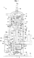
Fig. 1 is a longitudinal cross-sectional view of a compressor according to an embodiment of the present disclosure. -
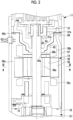
Fig. 2 is a longitudinal cross-sectional view showing a main part of the compressor ofFig. 1 . -
Fig. 3 is a cross-sectional view taken along cutting line III-III ofFig. 2 . -
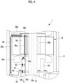
Fig. 4 is a longitudinal cross-sectional view showing a flow of a refrigerant by a guide pipe. -
Fig. 5 is a longitudinal cross-sectional view showing a modification example ofFig. 4 . -
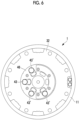
Fig. 6 is a cross-sectional view taken along cutting line VI-VI ofFig. 5 . - Hereinafter, an embodiment according to the present disclosure will be described with reference to the drawings.
- As shown in
Fig. 1 , acompressor 1 is used for an air conditioner and compresses a refrigerant R, which is, for example, a gas such as carbon dioxide, in two stages. Thecompressor 1 is fixed to an installation surface FL vialeg portions 3. Thecompressor 1 includes ahousing 11 and includes a rotary compression mechanism (low-stage-side compression mechanism) 12, a scroll compression mechanism (high-stage-side compression mechanism) 13, anelectric motor 14, and a rotary shaft (rotary shaft portion) 15, which are provided inside thehousing 11. - The
housing 11 has amain body portion 21 having a cylindrical shape, and anupper cover portion 22 and alower cover portion 23 that close upper and lower openings of themain body portion 21. The inside of thehousing 11 forms a sealed space. - The
rotary shaft 15 is provided to extend vertically along an axis X inside thehousing 11. An upper end (one end) side of therotary shaft 15 is rotatably supported by anupper bearing 31. A lower end (other end) side of therotary shaft 15 is rotatably supported by alower bearing 32. - The
electric motor 14 is disposed at a center of therotary shaft 15 in a longitudinal direction and on an outer peripheral side of therotary shaft 15, and rotates therotary shaft 15 around the axis X. Theelectric motor 14 includes arotor 38 fixed to an outer peripheral surface of therotary shaft 15, and astator 39 that faces therotor 38 in a radial direction with a gap from an outer peripheral surface of therotor 38 and that is fixed to an inner wall of themain body portion 21 of thehousing 11 by shrink fitting or the like. - The
rotor 38 is provided with rotor passages (through-hole) 38a provided at a predetermined interval in a circumferential direction. Eachrotor passage 38a penetrates therotor 38 in a vertical direction (axis X direction). The refrigerant discharged from arotary compression mechanism 12 flows upward through therotor passages 38a. An oil separation plate (baffle plate) 38b is fixed to an upper portion of therotor 38. Theoil separation plate 38b has a circular plate shape and is disposed to extend in a horizontal direction. Theoil separation plate 38b rotates around the axis X together with therotor 38. - A plurality of
stator passages 39a are formed in an outer periphery of thestator 39 at a predetermined angular interval in a circumferential direction (specifically, it will be described later with reference toFig. 3 ). - As shown in
Fig. 1 , anupper coil end 39b in which a winding is folded back is located at an upper portion of thestator 39, and alower coil end 39c in which a winding is folded back is located at a lower portion of thestator 39. Theelectric motor 14 is connected to a power source via an inverter (not shown) and rotates therotary shaft 15 with a variable frequency. - The
rotary compression mechanism 12 is provided on the lower end (other end) side of therotary shaft 15 inside thehousing 11. Therotary compression mechanism 12 is a two-cylinder mechanism in the present embodiment, and includes aneccentric shaft portion 41 provided in therotary shaft 15, arotor 42 fixed to theeccentric shaft portion 41 and rotating in a compression chamber C1 eccentrically with respect to the axis X as therotary shaft 15 rotates, and acylinder 44 in which the compression chamber C1 is formed. - The refrigerant R is supplied to the compression chamber C1 formed in the
cylinder 44 from asuction pipe 33. The refrigerant compressed in the compression chamber C1 is discharged from aguide pipe 43 to a region below theelectric motor 14 in thehousing 11 via the lower bearing 32 (specifically, a discharge space S formed inside the lower bearing 32). - The
cylinder 44 is fixed to thelower bearing 32 from below by abolt 48. Anoil pump 49 fixed by thebolt 48 together with thecylinder 44 is provided below thecylinder 44. The oil is sucked from an oil reservoir O1 in a lower portion of thehousing 11 by theoil pump 49, and is guided to theupper bearing 31 side through anoil supply hole 15a penetrating therotary shaft 15 along the axis X. - A
scroll compression mechanism 13 is disposed above theelectric motor 14 inside thehousing 11. Thescroll compression mechanism 13 includes a fixedscroll 51 fixed to theupper bearing 31, and anorbiting scroll 57 disposed below the fixedscroll 51 to face the fixedscroll 51. - The fixed
scroll 51 has anend plate 52 fixed to an upper surface of theupper bearing 31 and a fixedwrap 53 protruding downward from theend plate 52. Adischarge hole 52a vertically penetrating theend plate 52 is formed in a central portion (vicinity of the axis X) of theend plate 52. - The orbiting
scroll 57 is disposed to be interposed between theupper bearing 31 and the fixedscroll 51. Theorbiting scroll 57 has anend plate 58 connected to an upper end side of therotary shaft 15 and an orbitingwrap 59 protruding upward from theend plate 58. - The
end plate 58 is fixed to theeccentric shaft portion 56 provided at the upper end of therotary shaft 15 via abush 55, and rotates eccentrically with respect to the axis X as therotary shaft 15 rotates. - The orbiting
wrap 59 forms a compression chamber C2 for compressing the refrigerant R between the orbitingwrap 59 and thefixed wrap 53 by meshing with thefixed wrap 53. - A
balance weight chamber 63 is formed between a recessed portion on a central side of theupper bearing 31 and a lower side of the orbitingscroll 57. In thebalance weight chamber 63, abalance weight 54 rotates together with therotary shaft 15. - The refrigerant R compressed by the
rotary compression mechanism 12 and discharged into thehousing 11 is sucked into the compression chamber C2 from an outer peripheral side of thescroll compression mechanism 13 and is compressed toward a center side. The compressed refrigerant R is discharged from adischarge pipe 34 to the outside of thehousing 11 via thedischarge hole 52a of the fixedscroll 51. - A
cover 45 is provided below theupper bearing 31 so as to cover theupper bearing 31. Thecover 45 is formed by sheet metal processing, and has a substantially conical shape that is expanded in diameter from the lower side to the upper side. An upper end of thecover 45 on an outer peripheral side is fixed to theupper bearing 31 by abolt 45b (refer toFig. 2 ). - A
suction opening 45a is provided at a lower end of thecover 45. That is, thesuction opening 45a faces downward and is an annular region formed between thecover 45 and therotary shaft 15. A space below thehousing 11 and a space on theupper bearing 31 side are partitioned by thecover 45, and only the refrigerant sucked from thesuction opening 45a is guided to thescroll compression mechanism 13. - An
oil level tank 60 is provided outside and below thehousing 11. Theoil level tank 60 is a hollow container and communicates with the inside of thehousing 11 via alower pipe 61 and an upperpressure equalization pipe 62. Theoil level tank 60 measures an oil level of the oil reservoir O1 by guiding the oil from the oil reservoir O1 in thehousing 11 via thelower pipe 61. - A downstream end of an oil separator
oil return pipe 65 is connected to a lower side portion of thehousing 11. An upstream end of the oil separatoroil return pipe 65 is connected to an oil separator (not shown). The oil separated by the oil separator from the refrigerant discharged from thecompressor 1 is returned to the oil reservoir O1 in thehousing 11 via the oil separatoroil return pipe 65. A height position where the downstream end of the oil separatoroil return pipe 65 is connected to thehousing 11 is below thelower bearing 32. - An
oil return pipe 67 that is in contact with an inner wall of thehousing 11 and extends in a vertical direction is provided in thehousing 11. As shown inFig. 2 , an upper end (one end) of theoil return pipe 67 is fixed to theupper bearing 31 via aboss 68, and a lower end (other end) is provided to be located in the oil reservoir O1 in the lower portion of thehousing 11. The lower end of theoil return pipe 67 is fixed to the inner wall of thehousing 11 via a rod-shapedmember 70. - The
oil return pipe 67 is provided to penetrate a space formed between thestator 39 and thehousing 11. Specifically, as shown inFig. 3 , cutouts are provided in the outer periphery of thestator 39 in a circumferential direction at a predetermined angular interval so that the plurality ofstator passages 39a are formed with the inner wall of thehousing 11. The refrigerant or the oil flows through thestator passages 39a. Twooil return pipes 67 are inserted through one or a plurality of thestator passages 39a. - As can be seen from
Fig. 3 , therotor passages 38a are provided at a predetermined interval in the circumferential direction. The refrigerant discharged from arotary compression mechanism 12 flows upward through therotor passages 38a. - In addition, as shown in
Fig. 2 , a stabilizingplate 75 is fixed to a lower surface of the lower bearing 32 (refer toFig. 1 ). The stabilizingplate 75 is fixed to the lower bearing 32 (specifically, a leg portion protruding in a radial direction of the lower bearing 32) by a bolt. The stabilizingplate 75 is a circular plate in which an opening is formed at the center. The stabilizingplate 75 covers an upper side of an oil surface of the oil reservoir O1 to stabilize the oil surface. - As shown in
Fig. 4 , an annularflat plate 46 is fixed to an upper surface of thelower bearing 32 bybolts 47. A plurality of flat plate openings penetrating theflat plate 46 in a vertical direction are formed in theflat plate 46. Each flat plate opening communicates with abearing opening 32a formed in thelower bearing 32. In addition, a plurality of (in the present embodiment, four (refer toFig. 6 ) as an example) guidepipes 43 are provided on an upper surface of theflat plate 46. A diameter of each flat plate opening is formed to be slightly larger than an outer diameter of theguide pipe 43. A lower end portion of theguide pipe 43 is fitted to the flat plate opening. That is, arefrigerant inlet 43b provided at a lower end (upstream end) of theguide pipe 43 communicates with thebearing opening 32a formed in thelower bearing 32.Fig. 6 is a view showing a modification example of the present embodiment, but the number and the disposition of theguide pipes 43 are the same as those in the present embodiment. - The plurality of
guide pipes 43 are disposed side by side in a circumferential direction (refer toFig. 6 ). The plurality ofguide pipes 43 are not disposed to be aligned at equal intervals in the circumferential direction. The plurality ofguide pipes 43 are disposed so as not to be disposed directly above a discharge valve (not shown) provided in therotary compression mechanism 12. In addition, the plurality ofguide pipes 43 are disposed to be shifted to one side. For example, the plurality ofguide pipes 43 are disposed such that, in a plan view, central axes of theguide pipes 43 fall within a range of 180 degrees about a central axis of therotary compression mechanism 12. The disposition of the plurality ofguide pipes 43 is an example and is not limited thereto. In addition, the discharge valve is a valve provided at a discharge port (not shown) for discharging the refrigerant compressed by therotary compression mechanism 12 to the discharge space S. In this way, since theguide pipe 43 is not disposed directly above the discharge valve, a muffler effect is achieved, and thus noise can be reduced. - The
guide pipe 43 is provided above therotary compression mechanism 12 and guides the refrigerant discharged from therotary compression mechanism 12 to therotor passage 38a. As shown inFig. 4 , theguide pipe 43 is a cylindrical member formed in a linear shape. Theguide pipe 43 extends linearly along a vertical direction (axis X direction). Theguide pipe 43 extends to the vicinity of a lower end of therotor 38. An upper end of theguide pipe 43 is located above a lower end of thelower coil end 39c. - In addition, the
guide pipe 43 is disposed to overlap therotor 38 when viewed in the axis X direction. Specifically, theguide pipe 43 is disposed to overlap therotor passage 38a formed in therotor 38 when viewed in the axis X direction. More specifically, theguide pipe 43 is disposed to overlap an opening in which arefrigerant outlet 43a is formed at a lower end of therotor passage 38a. - The
compressor 1 having the above-described configuration operates as follows. - The refrigerant evaporated in an evaporator (not shown) is sucked into the
compressor 1 from thesuction pipe 33 and is compressed by therotary compression mechanism 12. The refrigerant compressed by therotary compression mechanism 12 is discharged from theguide pipe 43 into thehousing 11. - The refrigerant discharged into the
housing 11 is sucked from thesuction opening 45a of thecover 45, and is guided to thescroll compression mechanism 13 through a flow path in thecover 45 to be compressed. The refrigerant compressed by thescroll compression mechanism 13 is discharged from thedischarge pipe 34 to an external gas cooler or condenser through thedischarge hole 52a of the fixedscroll 51. - The oil is separated from the refrigerant discharged from the
discharge pipe 34 by an oil separator (not shown). The separated oil is returned to thehousing 11 through the oil separatoroil return pipe 65, and is stored in the oil reservoir O1. - The oil stored in the oil reservoir O1 is sucked up by the
oil pump 49, and is guided to thescroll compression mechanism 13 side through theoil supply hole 15a formed in therotary shaft 15. The oil guided to thescroll compression mechanism 13 side is returned to the oil reservoir O1 on the lower side after lubricating a sliding portion such as a bearing portion of theupper bearing 31 and thebush 55. The oil after lubrication, which is guided to thebalance weight chamber 63, is guided to theoil return pipe 67 through the oil return hole 31a and thevertical hole 31b (refer toFig. 2 ) formed in theupper bearing 31. - The oil guided to the
oil return pipe 67 is discharged from the lower end through a flow path inside theoil return pipe 67, and is returned to the oil reservoir O1. -
Fig. 5 schematically shows the flow of the refrigerant and the oil formed by thecover 45. In the drawing, the flow of the refrigerant is indicated by a white arrow, and the flow of the oil is indicated by a black arrow. - The refrigerant compressed by the
rotary compression mechanism 12 is discharged to the discharge space S formed in thelower bearing 32. The refrigerant discharged into the discharge space S passes through thebearing opening 32a formed in an upper end of thelower bearing 32 and flows into theguide pipe 43. The refrigerant flowing into theguide pipe 43 flows upward in theguide pipe 43 and is discharged from therefrigerant outlet 43a formed in an upper end (downstream end) of theguide pipe 43. The refrigerant discharged from theguide pipe 43 flows into therotor passage 38a formed in therotor 38. In this way, the refrigerant discharged from therotary compression mechanism 12 is guided from a lower side to an upper side of therotor 38 through therotor passage 38a. At this time, the oil is carried with the refrigerant. - The refrigerant and the oil that have come out of the
rotor passage 38a collide with theoil separation plate 38b and are guided in a radial direction about the axis X by a centrifugal force. Then, the oil having a larger specific gravity larger than the refrigerant collides with the inner wall of thehousing 11 and flows downward by gravity. A part of the oil flows upward together with the refrigerant in a space between the inner wall of thehousing 11 and theupper coil end 39b. The part of the oil that has ascended together with the refrigerant collides with an upper end of an outer periphery of the cover 45 (refer toFigs. 1 and2 ), and then falls downward by gravity. - According to the present embodiment, the following operations and effects are achieved.
- In the present embodiment, the refrigerant discharged from the
rotary compression mechanism 12 is guided to therotor passage 38a by theguide pipe 43 that is a straight pipe. Since theguide pipe 43 has a relatively simple shape, theguide pipe 43 can be manufactured without using a large device (for example, a mold or the like). Accordingly, compared to a case where the refrigerant is guided to therotor passage 38a by a component having a complicated shape (a deep-drawn sheet metal component such as a muffler cover) that needs to be manufactured by a mold or the like, it is not necessary to prepare a large device, and thus initial costs can be reduced. Therefore, the costs can be reduced, particularly in a compressor or the like produced in small quantities. - In addition, in the present embodiment, the
guide pipe 43 is disposed to overlap therotor passage 38a formed in therotor 38. As a result, a position of theguide pipe 43 becomes close to a position of therotor passage 38a. Therefore, the refrigerant can be easily guided from theguide pipe 43 to therotor passage 38a. - In the above-described embodiment, an example in which the
guide pipe 43 is a straight pipe has been described. However, the present disclosure is not limited thereto. For example, as shown inFigs. 5 and6 , a guide pipe 43' of which an upper end portion is curved to a radial inner side (therotor passage 38a side) may be used. The guide pipe 43' is curved such that therefrigerant outlet 43a is closer to therotor passage 38a than therefrigerant inlet 43b when viewed in the axis X direction. - With such a configuration, a position of the
refrigerant outlet 43a becomes close to a position of therotor passage 38a. Therefore, the refrigerant can be more easily guided from the guide pipe 43' to therotor passage 38a. - The guide pipe may be inclined such that the upper end of the guide pipe is close to the
rotor passage 38a. - The compressor described in the embodiment described above is understood as follows, for example.
- A compressor according to an aspect of the present disclosure includes a housing (11); a rotary shaft portion (15) that is accommodated in the housing and that rotates around a longitudinal axis; a low-stage-side compression mechanism (12) that is connected to a lower end of the rotary shaft portion and that compresses and discharges a refrigerant; an electric motor (14) that includes a rotor (38) fixed to the rotary shaft portion and having a through-hole (38a) penetrating the rotor in a direction of the longitudinal axis (axis X) to upwardly guide the refrigerant discharged from the low-stage-side compression mechanism and that is provided at a center of the rotary shaft portion in the direction of the longitudinal axis to rotationally drive the rotary shaft portion; a high-stage-side compression mechanism (13) that is connected to an upper end of the rotary shaft portion and that sucks and compresses the refrigerant discharged from the through-hole; and a tubular guide pipe (43) that is provided above the low-stage-side compression mechanism and that guides the refrigerant discharged from the low-stage-side compression mechanism to the through-hole, in which the guide pipe is disposed to overlap the rotor when viewed in the direction of the longitudinal axis.
- In the above configuration, the refrigerant discharged from the low-stage-side compression mechanism is guided to the through-hole by the tubular guide pipe. Since the guide pipe has a relatively simple shape, the guide pipe can be manufactured without using a large device (for example, a mold or the like). Accordingly, compared to a case where the refrigerant is guided to the through-hole by a component having a complicated shape (a deep-drawn sheet metal component such as a muffler cover) that needs to be manufactured by a mold or the like, it is not necessary to prepare a large device, and thus initial costs can be reduced. Therefore, the costs can be reduced, particularly in a compressor or the like produced in small quantities.
- In addition, in the above configuration, the guide pipe is disposed to overlap the rotor. As a result, the position of the guide pipe becomes close to the position of the through-hole. Therefore, the refrigerant can be easily guided from the guide pipe to the through-hole.
- In addition, in the compressor according to the aspect of the present disclosure, the guide pipe is disposed to overlap the through-hole when viewed in a direction of the longitudinal axis.
- The compressor according to
claim 1, in which the guide pipe is disposed to overlap the through-hole when viewed in a direction of the longitudinal axis. - In addition, in the compressor according to the aspect of the present disclosure, the guide pipe is curved such that an upper end thereof provided with a refrigerant outlet (43a) through which the refrigerant is discharged is close to the through-hole when viewed in the direction of the longitudinal axis.
- In the above configuration, the position of the refrigerant outlet through which the refrigerant is discharged is close to the position of the through-hole. Therefore, the refrigerant can be more easily guided from the guide pipe to the through-hole.
-
- 1: compressor
- 3: leg portion
- 11: housing
- 12: rotary compression mechanism (low-stage-side compression mechanism)
- 13: scroll compression mechanism (high-stage-side compression mechanism)
- 14: electric motor
- 15: rotary shaft (rotary shaft portion)
- 15a: oil supply hole
- 21: main body portion
- 22: upper cover portion
- 23: lower cover portion
- 31: upper bearing
- 31a: oil return hole
- 31b: vertical hole
- 32: lower bearing
- 32a: bearing opening
- 33: suction pipe
- 34: discharge pipe
- 38: rotor
- 38a: rotor passage (through-hole)
- 38b: oil separation plate
- 39: stator
- 39a: stator passage
- 39b: upper coil end
- 39c: lower coil end
- 41: eccentric shaft portion
- 42: rotor
- 43: guide pipe
- 43a: refrigerant outlet
- 43b: refrigerant inlet
- 44: cylinder
- 45: cover
- 45a: suction opening
- 46: flat plate
- 47: bolt
- 48: bolt
- 49: oil pump
- 51: fixed scroll
- 52: end plate
- 52a: discharge hole
- 53: fixed wrap
- 54: balance weight
- 55: bush
- 56: eccentric shaft portion
- 57: orbiting scroll
- 58: end plate
- 59: orbiting wrap
- 60: oil level tank
- 61: lower pipe
- 62: pressure equalization pipe
- 63: balance weight chamber
- 65: oil separator oil return pipe
- 67: oil return pipe
- 68: boss
- 70: rod-shaped member
- 75: stabilizing plate
- C1: compression chamber
- C2: compression chamber
- FL: installation surface
- O1: oil reservoir
- X: axis
- S: discharge space
Claims (3)
- A compressor comprising:a housing;a rotary shaft portion that is accommodated in the housing and that rotates around a longitudinal axis;a low-stage-side compression mechanism that is connected to a lower end of the rotary shaft portion and that compresses and discharges a refrigerant;an electric motor that includes a rotor fixed to the rotary shaft portion and having a through-hole penetrating the rotor in a direction of the longitudinal axis to upwardly guide the refrigerant discharged from the low-stage-side compression mechanism and that is provided at a center of the rotary shaft portion in the direction of the longitudinal axis to rotationally drive the rotary shaft portion;a high-stage-side compression mechanism that is connected to an upper end of the rotary shaft portion and that sucks and compresses the refrigerant discharged from the through-hole; anda tubular guide pipe that is provided above the low-stage-side compression mechanism and that guides the refrigerant discharged from the low-stage-side compression mechanism to the through-hole,wherein the guide pipe is disposed to overlap the rotor when viewed in the direction of the longitudinal axis.
- The compressor according to claim 1, wherein the guide pipe is disposed to overlap the through-hole when viewed in the direction of the longitudinal axis.
- The compressor according to Claim 1 or 2,
wherein the guide pipe is curved such that an upper end thereof provided with a refrigerant outlet through which the refrigerant is discharged is close to the through-hole when viewed in the direction of the longitudinal axis.
Applications Claiming Priority (2)
| Application Number | Priority Date | Filing Date | Title |
|---|---|---|---|
| JP2021189463A JP2023076188A (en) | 2021-11-22 | 2021-11-22 | compressor |
| PCT/JP2022/040221 WO2023090118A1 (en) | 2021-11-22 | 2022-10-27 | Compressor |
Publications (2)
| Publication Number | Publication Date |
|---|---|
| EP4400721A1 true EP4400721A1 (en) | 2024-07-17 |
| EP4400721A4 EP4400721A4 (en) | 2024-12-18 |
Family
ID=86396752
Family Applications (1)
| Application Number | Title | Priority Date | Filing Date |
|---|---|---|---|
| EP22895401.2A Pending EP4400721A4 (en) | 2021-11-22 | 2022-10-27 | COMPRESSOR |
Country Status (3)
| Country | Link |
|---|---|
| EP (1) | EP4400721A4 (en) |
| JP (1) | JP2023076188A (en) |
| WO (1) | WO2023090118A1 (en) |
Family Cites Families (4)
| Publication number | Priority date | Publication date | Assignee | Title |
|---|---|---|---|---|
| JP2009047039A (en) * | 2007-08-17 | 2009-03-05 | Mitsubishi Heavy Ind Ltd | Multistage compressor |
| JP2010053778A (en) * | 2008-08-28 | 2010-03-11 | Toshiba Carrier Corp | Hermetic compressor and refrigerating cycle device using the same |
| JP5709544B2 (en) * | 2011-01-17 | 2015-04-30 | 三菱重工業株式会社 | Compressor |
| JP6755114B2 (en) | 2016-04-14 | 2020-09-16 | 三菱重工サーマルシステムズ株式会社 | Sealed two-stage compressor |
-
2021
- 2021-11-22 JP JP2021189463A patent/JP2023076188A/en active Pending
-
2022
- 2022-10-27 EP EP22895401.2A patent/EP4400721A4/en active Pending
- 2022-10-27 WO PCT/JP2022/040221 patent/WO2023090118A1/en not_active Ceased
Also Published As
| Publication number | Publication date |
|---|---|
| JP2023076188A (en) | 2023-06-01 |
| EP4400721A4 (en) | 2024-12-18 |
| WO2023090118A1 (en) | 2023-05-25 |
Similar Documents
| Publication | Publication Date | Title |
|---|---|---|
| EP2312164B1 (en) | Scroll compressor | |
| EP2218914A2 (en) | Scroll-type fluid machine | |
| EP2177768A1 (en) | Multi-stage compressor | |
| US6428296B1 (en) | Horizontal scroll compressor having an oil injection fitting | |
| US20090136372A1 (en) | Open drive scroll compressor with lubrication system | |
| US20200003199A1 (en) | Compressor | |
| EP3575605B1 (en) | Hermetic compressor | |
| US5013225A (en) | Lubrication system for a scroll compressor | |
| JP4307945B2 (en) | Horizontal rotary compressor | |
| EP1764507A2 (en) | Compressor | |
| EP4400722B1 (en) | Compressor | |
| JP3925229B2 (en) | Hermetic scroll compressor, refrigeration cycle and refrigeration apparatus using the same | |
| EP3409948B1 (en) | Hermetic two-stage compressor | |
| EP4400716B1 (en) | Compressor | |
| JP2020045778A (en) | Compressor | |
| EP4621241A1 (en) | Compressor | |
| EP4400724A1 (en) | Compressor | |
| WO2023090118A1 (en) | Compressor | |
| KR20100010460A (en) | Rotary compressors | |
| EP4621240A1 (en) | Balance weight and compressor provided with same | |
| EP3992461B1 (en) | Scroll compressor | |
| JP5540577B2 (en) | Scroll compressor | |
| EP3971420A1 (en) | Compressor, and refrigeration device | |
| JP6711136B2 (en) | Scroll compressor | |
| JP2013241902A (en) | Compressor with oil separator |
Legal Events
| Date | Code | Title | Description |
|---|---|---|---|
| STAA | Information on the status of an ep patent application or granted ep patent |
Free format text: STATUS: THE INTERNATIONAL PUBLICATION HAS BEEN MADE |
|
| PUAI | Public reference made under article 153(3) epc to a published international application that has entered the european phase |
Free format text: ORIGINAL CODE: 0009012 |
|
| STAA | Information on the status of an ep patent application or granted ep patent |
Free format text: STATUS: REQUEST FOR EXAMINATION WAS MADE |
|
| 17P | Request for examination filed |
Effective date: 20240411 |
|
| AK | Designated contracting states |
Kind code of ref document: A1 Designated state(s): AL AT BE BG CH CY CZ DE DK EE ES FI FR GB GR HR HU IE IS IT LI LT LU LV MC ME MK MT NL NO PL PT RO RS SE SI SK SM TR |
|
| A4 | Supplementary search report drawn up and despatched |
Effective date: 20241118 |
|
| RIC1 | Information provided on ipc code assigned before grant |
Ipc: F04B 39/12 20060101ALI20241112BHEP Ipc: F04C 29/12 20060101ALI20241112BHEP Ipc: F04C 23/00 20060101AFI20241112BHEP |
|
| DAV | Request for validation of the european patent (deleted) | ||
| DAX | Request for extension of the european patent (deleted) |