EP4400217B1 - Mehrfachdüsenträger für ein landwirtschaftliches sprühsystem - Google Patents
Mehrfachdüsenträger für ein landwirtschaftliches sprühsystem Download PDFInfo
- Publication number
- EP4400217B1 EP4400217B1 EP24179732.3A EP24179732A EP4400217B1 EP 4400217 B1 EP4400217 B1 EP 4400217B1 EP 24179732 A EP24179732 A EP 24179732A EP 4400217 B1 EP4400217 B1 EP 4400217B1
- Authority
- EP
- European Patent Office
- Prior art keywords
- supply line
- nozzle holder
- latch
- receiving support
- pin
- Prior art date
- Legal status (The legal status is an assumption and is not a legal conclusion. Google has not performed a legal analysis and makes no representation as to the accuracy of the status listed.)
- Active
Links
Images


Classifications
-
- B—PERFORMING OPERATIONS; TRANSPORTING
- B05—SPRAYING OR ATOMISING IN GENERAL; APPLYING FLUENT MATERIALS TO SURFACES, IN GENERAL
- B05B—SPRAYING APPARATUS; ATOMISING APPARATUS; NOZZLES
- B05B1/00—Nozzles, spray heads or other outlets, with or without auxiliary devices such as valves, heating means
- B05B1/14—Nozzles, spray heads or other outlets, with or without auxiliary devices such as valves, heating means with multiple outlet openings; with strainers in or outside the outlet opening
- B05B1/16—Nozzles, spray heads or other outlets, with or without auxiliary devices such as valves, heating means with multiple outlet openings; with strainers in or outside the outlet opening having selectively- effective outlets
- B05B1/1609—Nozzles, spray heads or other outlets, with or without auxiliary devices such as valves, heating means with multiple outlet openings; with strainers in or outside the outlet opening having selectively- effective outlets with a selecting mechanism comprising a lift valve
-
- A—HUMAN NECESSITIES
- A01—AGRICULTURE; FORESTRY; ANIMAL HUSBANDRY; HUNTING; TRAPPING; FISHING
- A01G—HORTICULTURE; CULTIVATION OF VEGETABLES, FLOWERS, RICE, FRUIT, VINES, HOPS OR SEAWEED; FORESTRY; WATERING
- A01G7/00—Botany in general
- A01G7/06—Treatment of growing trees or plants, e.g. for preventing decay of wood, for tingeing flowers or wood, for prolonging the life of plants
-
- A—HUMAN NECESSITIES
- A01—AGRICULTURE; FORESTRY; ANIMAL HUSBANDRY; HUNTING; TRAPPING; FISHING
- A01M—CATCHING, TRAPPING OR SCARING OF ANIMALS; APPARATUS FOR THE DESTRUCTION OF NOXIOUS ANIMALS OR NOXIOUS PLANTS
- A01M7/00—Special adaptations or arrangements of liquid-spraying apparatus for purposes covered by this subclass
- A01M7/0025—Mechanical sprayers
- A01M7/0032—Pressure sprayers
-
- A—HUMAN NECESSITIES
- A01—AGRICULTURE; FORESTRY; ANIMAL HUSBANDRY; HUNTING; TRAPPING; FISHING
- A01M—CATCHING, TRAPPING OR SCARING OF ANIMALS; APPARATUS FOR THE DESTRUCTION OF NOXIOUS ANIMALS OR NOXIOUS PLANTS
- A01M7/00—Special adaptations or arrangements of liquid-spraying apparatus for purposes covered by this subclass
- A01M7/005—Special arrangements or adaptations of the spraying or distributing parts, e.g. adaptations or mounting of the spray booms, mounting of the nozzles, protection shields
- A01M7/006—Mounting of the nozzles
-
- B—PERFORMING OPERATIONS; TRANSPORTING
- B05—SPRAYING OR ATOMISING IN GENERAL; APPLYING FLUENT MATERIALS TO SURFACES, IN GENERAL
- B05B—SPRAYING APPARATUS; ATOMISING APPARATUS; NOZZLES
- B05B1/00—Nozzles, spray heads or other outlets, with or without auxiliary devices such as valves, heating means
- B05B1/14—Nozzles, spray heads or other outlets, with or without auxiliary devices such as valves, heating means with multiple outlet openings; with strainers in or outside the outlet opening
-
- B—PERFORMING OPERATIONS; TRANSPORTING
- B05—SPRAYING OR ATOMISING IN GENERAL; APPLYING FLUENT MATERIALS TO SURFACES, IN GENERAL
- B05B—SPRAYING APPARATUS; ATOMISING APPARATUS; NOZZLES
- B05B1/00—Nozzles, spray heads or other outlets, with or without auxiliary devices such as valves, heating means
- B05B1/30—Nozzles, spray heads or other outlets, with or without auxiliary devices such as valves, heating means designed to control volume of flow, e.g. with adjustable passages
- B05B1/3013—Lift valves
-
- B—PERFORMING OPERATIONS; TRANSPORTING
- B05—SPRAYING OR ATOMISING IN GENERAL; APPLYING FLUENT MATERIALS TO SURFACES, IN GENERAL
- B05B—SPRAYING APPARATUS; ATOMISING APPARATUS; NOZZLES
- B05B15/00—Details of spraying plant or spraying apparatus not otherwise provided for; Accessories
- B05B15/60—Arrangements for mounting, supporting or holding spraying apparatus
- B05B15/65—Mounting arrangements for fluid connection of the spraying apparatus or its outlets to flow conduits
- B05B15/658—Mounting arrangements for fluid connection of the spraying apparatus or its outlets to flow conduits the spraying apparatus or its outlet axis being perpendicular to the flow conduit
-
- B—PERFORMING OPERATIONS; TRANSPORTING
- B05—SPRAYING OR ATOMISING IN GENERAL; APPLYING FLUENT MATERIALS TO SURFACES, IN GENERAL
- B05B—SPRAYING APPARATUS; ATOMISING APPARATUS; NOZZLES
- B05B15/00—Details of spraying plant or spraying apparatus not otherwise provided for; Accessories
- B05B15/70—Arrangements for moving spray heads automatically to or from the working position
Definitions
- the present invention relates to the field of agricultural spraying systems. More specifically, the invention relates to spraying devices, comprising in particular multiple nozzle holders, i.e. carrying a plurality of spray nozzles.
- nozzle holders are known comprising a plurality of nozzles that can be active simultaneously, and having an identical or different flow rate. These nozzle holders are generally automatically controllable by means of an electric actuator, making it possible to select the active nozzle(s) by means of an active nozzle selection device.
- nozzle holders have the major drawback of seeing the entire mechanism for selecting the activated nozzles immersed in the fluid distributed by the spraying device.
- the product in contact with mechanical components that risk polluting said product before spraying.
- contact with a fluid that may include chemical agents, for example corrosive agents harms the lifespan of the device and is incompatible with a need to lubricate the moving mechanical elements, which also reduces their lifespan.
- the entire device must be sealed, all of these constraints limiting the choice of materials that can be used for manufacturing the nozzle holder.
- the invention aims to resolve the drawbacks of the state of the art, in particular by proposing a device for fixing a nozzle holder making it possible to limit the risk of the nozzle holder pivoting.
- the mechanical components involved in the kinematic control chain of such a nozzle holder are isolated from a fluid phytosanitary circulating from a spray line to the spray heads.
- a user can thus freely and remotely control the active nozzle without manual intervention, which simplifies the effective operating time of said nozzle holder.
- the response time for moving a valve from the open position to the closed position or from the closed position to the open position is not only configurable by the rotation speed transmitted by the actuator to the plate, but also by the inclination of the slope portions of the peripheral edge of the plate.
- valves of the plurality of valves are in the open position simultaneously, each first valve end contact surface being in contact with a single first edge of the plate.
- a fluid circulating in the nozzle holder can thus be sprayed by a plurality of nozzles simultaneously.
- the nozzle holder comprises an even number of valves associated two by two, the associated valves being arranged symmetrically with respect to a reference plane perpendicular to the plate, said plate comprising at least one given angular position for each pair of associated valves in a position of simultaneous opening of said pair of valves.
- each valve further comprises a mechanical compression spring connecting the valve to walls of the distribution chamber of the body; a second valve end configured to seal the passage orifices of the distribution chamber in the valve closing position, said second end further comprising sealing means.
- the mechanical spring makes it possible to maintain the valve in the closing position.
- the first contact end surface is carried by a tooth in contact with the peripheral edge of the plate.
- any rotation on itself of a valve is blocked.
- the sliding of the tooth on the edge of the plate is facilitated, in particular on the transitional zones, for example when passing the contact from a high portion to a sloping portion.
- an axis of rotation of the actuator is radially offset relative to an axis of rotation of the plate.
- a directional axis of the feed line may intersect the axis of rotation of the movable plate, which provides better balance when attaching the nozzle holder to said feed line.
- the actuator for example an electric stepper motor, may occupy a free volume depending on the desired motor power.
- the actuator comprises a pinion forming a gear connection with a toothing of the plate.
- the toothing of the plate occupies a circular sector greater than or equal to 120°.
- such a fastening device makes it possible to both fasten a nozzle holder to a fluid supply line while also providing a function of fastening a casing to a nozzle holder comprising, for example, an actuator such as a stepper electric motor configured to supply mechanical energy to the nozzle holder.
- the fastening device further allows for a nozzle holder architecture in which the majority of the mass of the casing is directly aligned with the supply line and the nozzle holder, which limits the risk of the nozzle holder pivoting under the action of a moment generated by the weight of the casing.
- the fixing device comprises a first receiving support located on one side of the nozzle holder and a second receiving support located on another side of the nozzle holder.
- the hinges of the two receiving supports each pivot relative to a pivot axis located on either side of the supply line.
- each of the pins pivots in one direction of rotation, which prevents the risk of accidental opening of the fixing device and the nozzle holder falling from the supply line.
- the hose clamp includes a curved tab.
- the curved tab allows a user to exert sufficient pressure to snap the hose clamp onto the supply line or disengage the clamp to the free position of the pin.
- each latch comprises a locking means in the closed position on the receiving support so that said locking means is retained by a stop of the receiving support when the fixing device is subjected to the weight of the nozzle holder.
- a locking means makes it easier to place the nozzle holder on the supply line before assembling the casing with the body of the nozzle holder followed by insertion of the pin and snapping of the clamp onto the supply line.
- the pivot connection between the body and the plate 14 is preferably provided by two lubricated plain bearings located at a central part of the plate 14, one of the plain bearings providing rotational guidance relative to the upper body part 10a and the other of the plain bearings providing rotational guidance relative to the intermediate body part 10b. Furthermore, the plate 14 is axially stopped on the one hand by a shoulder resting on the upper body part 10a and on the other hand by a shoulder resting on the intermediate body part 10b.
- the pivot connection can be provided by bearing rings, for example ball or roller bearing rings.
- the plate 14 has a cylindrical shape, a thickness of the plate 14 being substantially smaller than a radius of the plate 14.
- a peripheral edge of the plate 14 has high edge portions 141 and low edge portions 142 connected by sloping portions 143.
- the low edges 142 are axially closer to the intermediate body portion 10b and the high edges 141 are axially closer to the upper body portion 10a.
- the sloping edge portions 143 connect the high edges and the low edges so that the edge of the plate 14 is continuous.
- the plate 14 further comprises a toothing 144 for forming a gear connection with a pinion 160 of an actuator 16 intended to drive the plate 14 in rotation.
- the actuator 16 is for example an electric stepper motor, but may alternatively be a pneumatic or mechanical actuator.
- An axis of rotation 600 of the actuator 16 is offset radially relative to the axis of rotation 500 of the plate 14.
- the gear connection between the pinion 160 and the teeth 144 generates a multiplication or a reduction of the torque transmitted by the actuator 16 to the plate 14.
- the teeth 144 of the plate 14 occupies a circular sector, advantageously but not limited to greater than or equal to 120°.
- a stop screw 107 is offset radially towards the teeth 144 to serve as an end-of-travel stop for the rotation of the plate 14.
- the screw 107 makes it possible to define an origin for the angular orientation of the plate 14, in particular for the actuator 16, which corresponds to the nozzle position of the teeth 144 against the stop screw 107.
- the nozzle holder 1 comprises a plurality of valves 12 partly arranged in the distribution chamber 102, each of the valves 12 being movable between a position for sealingly closing the corresponding liquid passage orifice 103 of the distribution chamber and a position for opening said passage orifice.
- Each of the valves 12 comprises a first contact end surface 121 carried by a tooth 122 in contact with the peripheral edge of the plate 14.
- the valves 12 are connected to the upper body part 10a by mechanical springs 123 and extend through the compartment 106 towards the distribution chamber 102.
- the mechanical springs 123 are compression springs for maintaining contact between a second end 124 of the valve 12 and the liquid passage orifices 103 in the closed position of the valves 12.
- the second valve end 124 further comprises sealing means 125 intended to cooperate with the liquid passage orifices 103 to ensure sealing.
- the sealing means 125 are for example elastomer seals or circlips.
- the valves 12 may further comprise additional sealing means 126, in particular for the parts of each of the valves extending between the compartment 106 and the distribution chamber 102.
- the description here focuses on describing the operation of the nozzle holder 1.
- the supply line 2 supplies liquid, for example phytosanitary liquid, to the inlet pipe 101 towards the inlet chamber 102, via the solenoid valve 18 allowing the pressure and flow rate of the fluid entering the inlet chamber 102 to be modulated.
- the valves 12 being initially in the closed position, the inlet chamber 102 can thus fill with liquid.
- the teeth 122 of the valves 12 are in contact with each a lower portion 142 of the plate 14.
- the movable plate 14 is driven in rotation around the axis of rotation of the plate 500.
- each high border 141 and each low border 142 extend circumferentially along a given circular sector.
- the circular sectors of each of the high borders 141 and each of the low borders 142 may be different.
- the circular sectors of each edge such that for a nozzle holder, one to four valves 12, with a total of six different angular positions of the plate 14, results in six possible configurations of opening or closing of the four valves.
- four first angular positions correspond to a closing position of three of the valves 12 and to an opening position of the last valve 12, the valve 12 in the closing position being different for each of the first four angular positions of the plate 14.
- the remaining two angular positions correspond to configurations where two of the four valves 12 are in the opening position and the other two valves 12 are in the closing position, the two valves 12 in the closing position and the two valves 12 in the opening position being different for each of the remaining two angular positions.
- the nozzle holder 1 can thus spray liquid continuously through several spray heads 105 simultaneously.
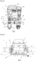
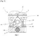
- THE figures 5 to 7 illustrate a nozzle holder 1 according to another aspect of the invention, relating to the fixing of the nozzle holder 1 on the supply line 2 by a fixing device 4.
- the pin 43 thus pivots between a clamping position in which the clamping collar 44 is elastically deformed to surround and clamp the outer periphery of the supply line 2 by a snap-fastening and a free position in which the clamping collar 44 is left free in its initial shape and the contact between the clamping collar 44 and the supply line 2 is broken.
- the clamping collar 44 comprises an eccentric 45 projecting radially relative to the direction of the supply line 2.
- the eccentric 45 in the clamping position of the pin 43 bears and exerts a stress on the tab of the casing 3.
- the pin 43 in the clamping position makes it possible to fix the nozzle holder 1 to the supply line 2, but also to keep the casing 3 secured to the upper body part 10a, thus ensuring the flow of a liquid from the supply line 2 to the intake pipe 101.
- the clamp 44 includes a curved tab 46.
- the curved tab 46 allows a user to exert sufficient pressure to snap the clamp 44 onto the supply line 2 or to disengage the clamp 44 to the free position of the pin 43.
- the nozzle holder may comprise an even number of valves 12, other than four, the valves 12 being associated two by two.
- the associated valves 12 are arranged symmetrically with respect to a reference plane perpendicular to the plate 14.
- the plate 14 may be oriented in at least one given angular position for each pair of valves 12 associated in a position of simultaneous opening of said pair of valves 12.
- the nozzle holder may contain an odd number of valves 12, the valves 12 may then be associated differently.
- the nozzle holder 1 may comprise a second shut-off valve, preferably arranged for example symmetrically on the intermediate body part 10b relative to the first shut-off valve.
Landscapes
- Life Sciences & Earth Sciences (AREA)
- Engineering & Computer Science (AREA)
- Wood Science & Technology (AREA)
- Environmental Sciences (AREA)
- Pest Control & Pesticides (AREA)
- Zoology (AREA)
- Insects & Arthropods (AREA)
- Biodiversity & Conservation Biology (AREA)
- Ecology (AREA)
- Forests & Forestry (AREA)
- Mechanical Engineering (AREA)
- Botany (AREA)
- Nozzles (AREA)
- Catching Or Destruction (AREA)
- Fertilizing (AREA)
Claims (5)
- Vorrichtung (4) zum Befestigen eines Düsenhalters (1) an einer Fluidversorgungsleitung (2) eines Sprühsystems, wobei die Vorrichtung (4) zum Befestigen eines Düsenhalters (1), umfassend einen Körper (10a, 10b, 10c) und ein Gehäuse (3), an einer Versorgungsleitung (2) konfiguriert ist, wobei sich die Versorgungsleitung (2) zwischen dem Körper (10a, 10b, 10c) des Düsenhalters (1) und dem Gehäuse (3) des Düsenhalters (1) erstreckt, die Befestigungsvorrichtung (4) umfassend:- mindestens einen Aufnahmeträger (40), der konfiguriert ist, um in zylindrischem Oberflächenkontakt mit der Versorgungsleitung (2) zu stehen;- mindestens einen Riegel (42);- ein Aufnahmeträgerscharnier (40), das die Schwenkung des Riegels (42) um eine erste Schwenkachse (700, 800) herum parallel zu der Richtung der Versorgungsleitung (2) ermöglicht, wobei der Riegel (42) zwischen einer geschlossenen Position, in der der Riegel (42) die Versorgungsleitung (2) an einem Außenumfang der Versorgungsleitung (2) umgibt, und einer offenen Position, in der der Kontakt zwischen dem Aufnahmeträger (40) und der Versorgungsleitung (2) unterbrochen sein kann, bewegbar ist; wobei die Vorrichtung (4) dadurch gekennzeichnet ist, dass die Vorrichtung zusätzlich umfasst- einen Stift (43) des Aufnahmeträgers (40), der es ermöglicht, den Riegel (42) in der geschlossenen Position durch Einführen in koaxiale Löcher des Riegels (42) und des Aufnahmeträgers (40) zu verriegeln, der Stift (43) umfassend eine Klemmschelle (44), die in einer ursprünglichen unverformten Form elastisch verformbar ist, wobei der Stift (43) um eine zweite Schwenkachse (700, 800) herum parallel zu der ersten Schwenkachse (700, 800) zwischen einer Klemmposition, in der die Klemmschelle (44) elastisch verformt ist, zum Umgeben und Festklemmen des Außenumfangs der Versorgungsleitung (2) durch Einschnappen, und einer freien Position, in der die Klemmschelle (44) in ihrer ursprünglichen Form frei gelassen wird, schwenken kann, wobei der Kontakt zwischen der Klemmschelle (44) und der Versorgungsleitung (2) unterbrochen ist;- die Klemmschelle (44) des Stifts (43) umfassend einen Exzenter (45), der radial zu der Richtung der Versorgungsleitung (2) vorspringt, wobei der Exzenter (45), in der Klemmposition des Stifts (43), zum Abdecken des Riegels (42) konfiguriert ist.
- Befestigungsvorrichtung (4) nach Anspruch 1, umfassend einen ersten Aufnahmeträger (40), der sich auf einer Seite des Düsenhalters (1) befindet, und einen zweiten Aufnahmeträger (40), der sich auf einer anderen Seite des Düsenhalters (1) befindet.
- Befestigungsvorrichtung (4) nach Anspruch 2, wobei die Scharniere der zwei Aufnahmeträger (40) jeweils relativ zu einer Schwenkachse (700, 800) schwenken, die sich auf beiden Seiten der Versorgungsleitung (2) befindet.
- Befestigungsvorrichtung (4) nach einem der vorstehenden Ansprüche, wobei die Klemmschelle (44) eine gekrümmte Lasche (46) aufweist.
- Befestigungsvorrichtung (4) nach einem der vorstehenden Ansprüche, wobei jeder Riegel (42) in der geschlossenen Position an dem Aufnahmeträger (40) ein Verriegelungsmittel umfasst, sodass die Verriegelungseinrichtung durch einen Anschlag des Aufnahmeträgers (40) festgehalten wird, wenn die Befestigungsvorrichtung (4) dem Gewicht des Düsenhalters (1) ausgesetzt ist.
Applications Claiming Priority (2)
| Application Number | Priority Date | Filing Date | Title |
|---|---|---|---|
| FR2213888A FR3143268B1 (fr) | 2022-12-19 | 2022-12-19 | Porte-buses multiple pour un système de pulvérisation agricole |
| EP23210742.5A EP4388872B1 (de) | 2022-12-19 | 2023-11-17 | Mehrfachdüsenträger für ein landwirtschaftliches sprühsystem |
Related Parent Applications (2)
| Application Number | Title | Priority Date | Filing Date |
|---|---|---|---|
| EP23210742.5A Division EP4388872B1 (de) | 2022-12-19 | 2023-11-17 | Mehrfachdüsenträger für ein landwirtschaftliches sprühsystem |
| EP23210742.5A Division-Into EP4388872B1 (de) | 2022-12-19 | 2023-11-17 | Mehrfachdüsenträger für ein landwirtschaftliches sprühsystem |
Publications (4)
| Publication Number | Publication Date |
|---|---|
| EP4400217A2 EP4400217A2 (de) | 2024-07-17 |
| EP4400217A3 EP4400217A3 (de) | 2024-10-16 |
| EP4400217B1 true EP4400217B1 (de) | 2025-07-02 |
| EP4400217C0 EP4400217C0 (de) | 2025-07-02 |
Family
ID=86272522
Family Applications (2)
| Application Number | Title | Priority Date | Filing Date |
|---|---|---|---|
| EP23210742.5A Active EP4388872B1 (de) | 2022-12-19 | 2023-11-17 | Mehrfachdüsenträger für ein landwirtschaftliches sprühsystem |
| EP24179732.3A Active EP4400217B1 (de) | 2022-12-19 | 2023-11-17 | Mehrfachdüsenträger für ein landwirtschaftliches sprühsystem |
Family Applications Before (1)
| Application Number | Title | Priority Date | Filing Date |
|---|---|---|---|
| EP23210742.5A Active EP4388872B1 (de) | 2022-12-19 | 2023-11-17 | Mehrfachdüsenträger für ein landwirtschaftliches sprühsystem |
Country Status (6)
| Country | Link |
|---|---|
| US (2) | US20240198365A1 (de) |
| EP (2) | EP4388872B1 (de) |
| AU (2) | AU2023278025B2 (de) |
| ES (2) | ES3038333T3 (de) |
| FR (2) | FR3143268B1 (de) |
| PL (2) | PL4400217T3 (de) |
Family Cites Families (13)
| Publication number | Priority date | Publication date | Assignee | Title |
|---|---|---|---|---|
| FR2655571A1 (fr) * | 1989-12-11 | 1991-06-14 | Tecnoma | Dispositif support de buses, a changement rapide. |
| US5697650A (en) * | 1995-04-20 | 1997-12-16 | Spraying Systems Co. | Corrosion-free clip eyelet for spray nozzles |
| US6036107A (en) * | 1998-03-31 | 2000-03-14 | Spraying System Co. | Control valve arrangement for spraying systems |
| DE102006006985A1 (de) * | 2006-02-15 | 2007-08-23 | Amazonen-Werke H. Dreyer Gmbh & Co. Kg | Mehrwegeventil |
| FR2955168B1 (fr) * | 2010-01-14 | 2012-02-10 | Mann & Hummel Gmbh | Vanne de commande pour circuit de circulation de liquide |
| DE102010036437A1 (de) * | 2010-07-16 | 2012-01-19 | Amazonen-Werke H. Dreyer Gmbh & Co. Kg | Mehrfachdüsenkörper |
| ITMO20120263A1 (it) * | 2012-10-29 | 2014-04-30 | Arag S R L | Gruppo portagetti multiplo ad incrementata flessibilita' di impiego |
| DE102013104674A1 (de) * | 2013-05-07 | 2014-11-27 | Amazonen-Werke H. Dreyer Gmbh & Co. Kg | Mehrfachdüsenkörper |
| US10189031B2 (en) * | 2014-06-20 | 2019-01-29 | Deere & Company | Hybrid flow nozzle and control system |
| US10444048B2 (en) * | 2014-12-19 | 2019-10-15 | Deere & Company | Fluid flow monitoring system |
| US10406551B2 (en) * | 2015-08-18 | 2019-09-10 | Deere & Company | Spray nozzle mounting for receiving fluid from distribution pipe |
| DE102018106334A1 (de) * | 2018-03-19 | 2019-09-19 | Amazonen-Werke H. Dreyer Gmbh & Co. Kg | Düsenanordnung für eine Feldspritze |
| DE102022111983A1 (de) * | 2022-05-12 | 2023-11-16 | Vermes Microdispensing GmbH | Dosierkopf für ein Dosiersystem |
-
2022
- 2022-12-19 FR FR2213888A patent/FR3143268B1/fr active Active
-
2023
- 2023-11-17 PL PL24179732.3T patent/PL4400217T3/pl unknown
- 2023-11-17 PL PL23210742.5T patent/PL4388872T3/pl unknown
- 2023-11-17 EP EP23210742.5A patent/EP4388872B1/de active Active
- 2023-11-17 ES ES24179732T patent/ES3038333T3/es active Active
- 2023-11-17 EP EP24179732.3A patent/EP4400217B1/de active Active
- 2023-11-17 ES ES23210742T patent/ES3035471T3/es active Active
- 2023-12-06 AU AU2023278025A patent/AU2023278025B2/en active Active
- 2023-12-13 US US18/538,636 patent/US20240198365A1/en active Pending
-
2024
- 2024-06-03 FR FR2405812A patent/FR3149165B1/fr active Active
- 2024-10-15 US US18/916,138 patent/US20250114805A1/en active Pending
- 2024-10-17 AU AU2024227399A patent/AU2024227399B2/en active Active
Also Published As
| Publication number | Publication date |
|---|---|
| FR3149165B1 (fr) | 2025-06-06 |
| US20250114805A1 (en) | 2025-04-10 |
| AU2024227399B2 (en) | 2026-02-05 |
| FR3143268A1 (fr) | 2024-06-21 |
| EP4400217A3 (de) | 2024-10-16 |
| PL4388872T3 (pl) | 2025-06-23 |
| FR3143268B1 (fr) | 2024-11-29 |
| AU2023278025A1 (en) | 2024-07-04 |
| PL4400217T3 (pl) | 2025-10-20 |
| FR3149165A1 (fr) | 2024-12-06 |
| EP4400217A2 (de) | 2024-07-17 |
| EP4400217C0 (de) | 2025-07-02 |
| ES3038333T3 (en) | 2025-10-10 |
| EP4388872A1 (de) | 2024-06-26 |
| EP4388872B1 (de) | 2025-05-14 |
| AU2024227399A1 (en) | 2024-11-07 |
| ES3035471T3 (en) | 2025-09-03 |
| US20240198365A1 (en) | 2024-06-20 |
| AU2023278025B2 (en) | 2026-02-05 |
| EP4388872C0 (de) | 2025-05-14 |
Similar Documents
| Publication | Publication Date | Title |
|---|---|---|
| FR3091842A1 (fr) | Système de nettoyage pour équipements d’un véhicule automobile et véhicule associé | |
| WO2020109685A1 (fr) | Aerateur mince a effet coanda pour vehicule automobile | |
| EP3300971A1 (de) | Reinigungsvorrichtung zum spritzen mindestens einer flüssigkeit auf eine zu reinigende oberfläche eines kraftfahrzeugs | |
| EP4388872B1 (de) | Mehrfachdüsenträger für ein landwirtschaftliches sprühsystem | |
| EP0884505B1 (de) | Vorrichtung mit einem drehbaren Hebel zur Bewegungsübertragung und Ventil mit einer solchen Vorrichtung | |
| EP3752380A2 (de) | Luftstromregelungsvorrichtung für ein stirnseitenmodul eines kraftfahrzeugs | |
| FR2549221A1 (fr) | Compteur a gaz | |
| EP1132667B1 (de) | System zur Reduziering des Querschnitts in einem Durchflusskanal | |
| FR2538862A2 (fr) | Dispositif hydraulique de commande pour un servomoteur, en particulier pour mecanismes de direction de vehicules | |
| EP3166823B1 (de) | Mechanischer verbinder für ein fahrzeugwindschutzscheibenwischerblatt | |
| FR3068415B1 (fr) | Pompe hydraulique pour interface de connexion hydraulique d'un mecanisme d'embrayage | |
| EP3538391A1 (de) | Verschlussvorrichtung für einen lufteinlass an der frontplatte eines kraftfahrzeugs | |
| FR2511786A1 (fr) | Module regleur d'echappement pour un distributeur d'un fluide sous pression | |
| FR2791114A1 (fr) | Dispositif permettant de commander l'ecoulement d'un fluide et l'orientation de cet ecoulement | |
| EP1875017B1 (de) | Roboter zur automatischen reinigung des bodens eines schwimmbeckens | |
| EP4407218B1 (de) | Ventilanordnung mit gemeinsamer motorisierter betätigungsvorrichtung | |
| EP2551572B1 (de) | Vorrichtung zum Betätigen und Sperren einer Funktionseinheit und Ventilmodul mit einem solchen Vorrichtung. | |
| FR2892342A1 (fr) | Dispositif permettant de commander l'ecoulement d'un fluide et d'orienter cet ecoulement dans une direction determinee | |
| FR3167907A3 (fr) | Distributeur hydraulique et dispositif de nettoyage associé | |
| FR3138488A1 (fr) | Distributeur a joint incorpore, et procede de realisation | |
| EP4671580A1 (de) | Kartuschenventil und zugehörige kartuschenventilanordnung | |
| WO2025132665A1 (fr) | Vanne séquentielle multidirectionnelle et système de projection de fluide de nettoyage | |
| FR2761323A1 (fr) | Essuie-glace de vehicule automobile comportant des moyens perfectionnes de projection de liquide de lavage | |
| FR3157844A1 (fr) | Balai d’essuyage et dispositif d’essuyage associé | |
| FR3083287A1 (fr) | Vanne de regulation amelioree |
Legal Events
| Date | Code | Title | Description |
|---|---|---|---|
| PUAI | Public reference made under article 153(3) epc to a published international application that has entered the european phase |
Free format text: ORIGINAL CODE: 0009012 |
|
| STAA | Information on the status of an ep patent application or granted ep patent |
Free format text: STATUS: THE APPLICATION HAS BEEN PUBLISHED |
|
| AC | Divisional application: reference to earlier application |
Ref document number: 4388872 Country of ref document: EP Kind code of ref document: P |
|
| AK | Designated contracting states |
Kind code of ref document: A2 Designated state(s): AL AT BE BG CH CY CZ DE DK EE ES FI FR GB GR HR HU IE IS IT LI LT LU LV MC ME MK MT NL NO PL PT RO RS SE SI SK SM TR |
|
| REG | Reference to a national code |
Ref country code: DE Ref legal event code: R079 Free format text: PREVIOUS MAIN CLASS: B05B0001160000 Ipc: A01M0007000000 Ref document number: 602023004569 Country of ref document: DE |
|
| PUAL | Search report despatched |
Free format text: ORIGINAL CODE: 0009013 |
|
| AK | Designated contracting states |
Kind code of ref document: A3 Designated state(s): AL AT BE BG CH CY CZ DE DK EE ES FI FR GB GR HR HU IE IS IT LI LT LU LV MC ME MK MT NL NO PL PT RO RS SE SI SK SM TR |
|
| RIC1 | Information provided on ipc code assigned before grant |
Ipc: B05B 15/658 20180101ALI20240910BHEP Ipc: A01M 7/00 20060101AFI20240910BHEP |
|
| STAA | Information on the status of an ep patent application or granted ep patent |
Free format text: STATUS: REQUEST FOR EXAMINATION WAS MADE |
|
| 17P | Request for examination filed |
Effective date: 20241202 |
|
| RBV | Designated contracting states (corrected) |
Designated state(s): AL AT BE BG CH CY CZ DE DK EE ES FI FR GB GR HR HU IE IS IT LI LT LU LV MC ME MK MT NL NO PL PT RO RS SE SI SK SM TR |
|
| GRAP | Despatch of communication of intention to grant a patent |
Free format text: ORIGINAL CODE: EPIDOSNIGR1 |
|
| STAA | Information on the status of an ep patent application or granted ep patent |
Free format text: STATUS: GRANT OF PATENT IS INTENDED |
|
| GRAS | Grant fee paid |
Free format text: ORIGINAL CODE: EPIDOSNIGR3 |
|
| INTG | Intention to grant announced |
Effective date: 20250428 |
|
| GRAA | (expected) grant |
Free format text: ORIGINAL CODE: 0009210 |
|
| STAA | Information on the status of an ep patent application or granted ep patent |
Free format text: STATUS: THE PATENT HAS BEEN GRANTED |
|
| AC | Divisional application: reference to earlier application |
Ref document number: 4388872 Country of ref document: EP Kind code of ref document: P |
|
| AK | Designated contracting states |
Kind code of ref document: B1 Designated state(s): AL AT BE BG CH CY CZ DE DK EE ES FI FR GB GR HR HU IE IS IT LI LT LU LV MC ME MK MT NL NO PL PT RO RS SE SI SK SM TR |
|
| REG | Reference to a national code |
Ref country code: GB Ref legal event code: FG4D Free format text: NOT ENGLISH |
|
| REG | Reference to a national code |
Ref country code: CH Ref legal event code: EP |
|
| REG | Reference to a national code |
Ref country code: DE Ref legal event code: R096 Ref document number: 602023004569 Country of ref document: DE |
|
| REG | Reference to a national code |
Ref country code: IE Ref legal event code: FG4D Free format text: LANGUAGE OF EP DOCUMENT: FRENCH |
|
| U01 | Request for unitary effect filed |
Effective date: 20250703 |
|
| U07 | Unitary effect registered |
Designated state(s): AT BE BG DE DK EE FI FR IT LT LU LV MT NL PT RO SE SI Effective date: 20250710 |
|
| REG | Reference to a national code |
Ref country code: ES Ref legal event code: FG2A Ref document number: 3038333 Country of ref document: ES Kind code of ref document: T3 Effective date: 20251010 |
|
| U20 | Renewal fee for the european patent with unitary effect paid |
Year of fee payment: 3 Effective date: 20251028 |
|
| PG25 | Lapsed in a contracting state [announced via postgrant information from national office to epo] |
Ref country code: IS Free format text: LAPSE BECAUSE OF FAILURE TO SUBMIT A TRANSLATION OF THE DESCRIPTION OR TO PAY THE FEE WITHIN THE PRESCRIBED TIME-LIMIT Effective date: 20251102 |
|
| PG25 | Lapsed in a contracting state [announced via postgrant information from national office to epo] |
Ref country code: NO Free format text: LAPSE BECAUSE OF FAILURE TO SUBMIT A TRANSLATION OF THE DESCRIPTION OR TO PAY THE FEE WITHIN THE PRESCRIBED TIME-LIMIT Effective date: 20251002 |
|
| PG25 | Lapsed in a contracting state [announced via postgrant information from national office to epo] |
Ref country code: HR Free format text: LAPSE BECAUSE OF FAILURE TO SUBMIT A TRANSLATION OF THE DESCRIPTION OR TO PAY THE FEE WITHIN THE PRESCRIBED TIME-LIMIT Effective date: 20250702 |
|
| PG25 | Lapsed in a contracting state [announced via postgrant information from national office to epo] |
Ref country code: GR Free format text: LAPSE BECAUSE OF FAILURE TO SUBMIT A TRANSLATION OF THE DESCRIPTION OR TO PAY THE FEE WITHIN THE PRESCRIBED TIME-LIMIT Effective date: 20251003 |
|
| PGFP | Annual fee paid to national office [announced via postgrant information from national office to epo] |
Ref country code: CZ Payment date: 20251114 Year of fee payment: 3 |
|
| PGFP | Annual fee paid to national office [announced via postgrant information from national office to epo] |
Ref country code: PL Payment date: 20251024 Year of fee payment: 3 |
|
| PG25 | Lapsed in a contracting state [announced via postgrant information from national office to epo] |
Ref country code: RS Free format text: LAPSE BECAUSE OF FAILURE TO SUBMIT A TRANSLATION OF THE DESCRIPTION OR TO PAY THE FEE WITHIN THE PRESCRIBED TIME-LIMIT Effective date: 20251002 |
|
| PGFP | Annual fee paid to national office [announced via postgrant information from national office to epo] |
Ref country code: ES Payment date: 20251210 Year of fee payment: 3 |
|
| PG25 | Lapsed in a contracting state [announced via postgrant information from national office to epo] |
Ref country code: SM Free format text: LAPSE BECAUSE OF FAILURE TO SUBMIT A TRANSLATION OF THE DESCRIPTION OR TO PAY THE FEE WITHIN THE PRESCRIBED TIME-LIMIT Effective date: 20250702 |
|
| PG25 | Lapsed in a contracting state [announced via postgrant information from national office to epo] |
Ref country code: SK Free format text: LAPSE BECAUSE OF FAILURE TO SUBMIT A TRANSLATION OF THE DESCRIPTION OR TO PAY THE FEE WITHIN THE PRESCRIBED TIME-LIMIT Effective date: 20250702 |
|
| PLBE | No opposition filed within time limit |
Free format text: ORIGINAL CODE: 0009261 |
|
| STAA | Information on the status of an ep patent application or granted ep patent |
Free format text: STATUS: NO OPPOSITION FILED WITHIN TIME LIMIT |