EP4400199A1 - Attachment structure for adsorption-desorption member - Google Patents
Attachment structure for adsorption-desorption member Download PDFInfo
- Publication number
- EP4400199A1 EP4400199A1 EP22867287.9A EP22867287A EP4400199A1 EP 4400199 A1 EP4400199 A1 EP 4400199A1 EP 22867287 A EP22867287 A EP 22867287A EP 4400199 A1 EP4400199 A1 EP 4400199A1
- Authority
- EP
- European Patent Office
- Prior art keywords
- adsorption
- desorption
- plate
- attachment
- annular
- Prior art date
- Legal status (The legal status is an assumption and is not a legal conclusion. Google has not performed a legal analysis and makes no representation as to the accuracy of the status listed.)
- Withdrawn
Links
Images



Classifications
-
- B—PERFORMING OPERATIONS; TRANSPORTING
- B01—PHYSICAL OR CHEMICAL PROCESSES OR APPARATUS IN GENERAL
- B01D—SEPARATION
- B01D53/00—Separation of gases or vapours; Recovering vapours of volatile solvents from gases; Chemical or biological purification of waste gases, e.g. engine exhaust gases, smoke, fumes, flue gases, aerosols
- B01D53/02—Separation of gases or vapours; Recovering vapours of volatile solvents from gases; Chemical or biological purification of waste gases, e.g. engine exhaust gases, smoke, fumes, flue gases, aerosols by adsorption, e.g. preparative gas chromatography
- B01D53/04—Separation of gases or vapours; Recovering vapours of volatile solvents from gases; Chemical or biological purification of waste gases, e.g. engine exhaust gases, smoke, fumes, flue gases, aerosols by adsorption, e.g. preparative gas chromatography with stationary adsorbents
-
- B—PERFORMING OPERATIONS; TRANSPORTING
- B01—PHYSICAL OR CHEMICAL PROCESSES OR APPARATUS IN GENERAL
- B01D—SEPARATION
- B01D53/00—Separation of gases or vapours; Recovering vapours of volatile solvents from gases; Chemical or biological purification of waste gases, e.g. engine exhaust gases, smoke, fumes, flue gases, aerosols
- B01D53/02—Separation of gases or vapours; Recovering vapours of volatile solvents from gases; Chemical or biological purification of waste gases, e.g. engine exhaust gases, smoke, fumes, flue gases, aerosols by adsorption, e.g. preparative gas chromatography
- B01D53/04—Separation of gases or vapours; Recovering vapours of volatile solvents from gases; Chemical or biological purification of waste gases, e.g. engine exhaust gases, smoke, fumes, flue gases, aerosols by adsorption, e.g. preparative gas chromatography with stationary adsorbents
- B01D53/0407—Constructional details of adsorbing systems
-
- B—PERFORMING OPERATIONS; TRANSPORTING
- B01—PHYSICAL OR CHEMICAL PROCESSES OR APPARATUS IN GENERAL
- B01D—SEPARATION
- B01D53/00—Separation of gases or vapours; Recovering vapours of volatile solvents from gases; Chemical or biological purification of waste gases, e.g. engine exhaust gases, smoke, fumes, flue gases, aerosols
- B01D53/02—Separation of gases or vapours; Recovering vapours of volatile solvents from gases; Chemical or biological purification of waste gases, e.g. engine exhaust gases, smoke, fumes, flue gases, aerosols by adsorption, e.g. preparative gas chromatography
- B01D53/06—Separation of gases or vapours; Recovering vapours of volatile solvents from gases; Chemical or biological purification of waste gases, e.g. engine exhaust gases, smoke, fumes, flue gases, aerosols by adsorption, e.g. preparative gas chromatography with moving adsorbents, e.g. rotating beds
-
- B—PERFORMING OPERATIONS; TRANSPORTING
- B01—PHYSICAL OR CHEMICAL PROCESSES OR APPARATUS IN GENERAL
- B01D—SEPARATION
- B01D53/00—Separation of gases or vapours; Recovering vapours of volatile solvents from gases; Chemical or biological purification of waste gases, e.g. engine exhaust gases, smoke, fumes, flue gases, aerosols
- B01D53/34—Chemical or biological purification of waste gases
- B01D53/38—Removing components of undefined structure
- B01D53/44—Organic components
-
- B—PERFORMING OPERATIONS; TRANSPORTING
- B01—PHYSICAL OR CHEMICAL PROCESSES OR APPARATUS IN GENERAL
- B01D—SEPARATION
- B01D53/00—Separation of gases or vapours; Recovering vapours of volatile solvents from gases; Chemical or biological purification of waste gases, e.g. engine exhaust gases, smoke, fumes, flue gases, aerosols
- B01D53/34—Chemical or biological purification of waste gases
- B01D53/74—General processes for purification of waste gases; Apparatus or devices specially adapted therefor
-
- B—PERFORMING OPERATIONS; TRANSPORTING
- B01—PHYSICAL OR CHEMICAL PROCESSES OR APPARATUS IN GENERAL
- B01D—SEPARATION
- B01D2259/00—Type of treatment
- B01D2259/40—Further details for adsorption processes and devices
- B01D2259/40083—Regeneration of adsorbents in processes other than pressure or temperature swing adsorption
- B01D2259/40084—Regeneration of adsorbents in processes other than pressure or temperature swing adsorption by exchanging used adsorbents with fresh adsorbents
-
- B—PERFORMING OPERATIONS; TRANSPORTING
- B01—PHYSICAL OR CHEMICAL PROCESSES OR APPARATUS IN GENERAL
- B01D—SEPARATION
- B01D2259/00—Type of treatment
- B01D2259/40—Further details for adsorption processes and devices
- B01D2259/40083—Regeneration of adsorbents in processes other than pressure or temperature swing adsorption
- B01D2259/40086—Regeneration of adsorbents in processes other than pressure or temperature swing adsorption by using a purge gas
Definitions
- the present disclosure relates to a structure for attachment of an adsorption and desorption member.
- An adsorption and desorption treatment apparatus including an adsorption and desorption member including an adsorption and desorption element has conventionally been known as an organic solvent containing gas treatment system that cleans raw gas containing an organic solvent by separating the organic solvent from raw gas and emits cleaned gas and recovers the organic solvent separated from the raw gas with carrier gas (see PTL 1, PTL 2, and PTL 3).
- An object of the present disclosure is to provide a structure for attachment of an adsorption and desorption member that prevents gas leakage in an attachment region involved with replacement of the adsorption and desorption member.
- a structure for attachment of an adsorption and desorption member in the present disclosure relates to a structure for attachment of an adsorption and desorption member that is arranged in an adsorption and desorption treatment apparatus to adsorb and desorb an organic solvent, the adsorption and desorption treatment apparatus cleaning raw gas containing the organic solvent by separating the organic solvent from the raw gas and emitting cleaned gas and recovering the organic solvent separated from the raw gas with carrier gas.
- a plate-shaped member, an annular erected wall, and an annular plate are provided, the plate-shaped member being provided with one open hole or at least two open holes for insertion of the adsorption and desorption member, the annular erected wall being erected upward from the plate-shaped member and provided to surround an edge of the open hole, the annular plate extending outward from an upper end of the annular erected wall.
- the adsorption and desorption member includes a cylindrical adsorption and desorption element and an attachment plate, the attachment plate being provided on an upper surface of the adsorption and desorption element and including a flange portion that extends outward from an edge of the adsorption and desorption element.
- An attachment region is provided at a position where the flange portion and the annular plate are superimposed on each other when the adsorption and desorption member is accommodated in the inside of the adsorption and desorption treatment apparatus by being inserted in the open hole.
- the attachment region includes a hexagon head bolt and a nut.
- the flange portion is provided with a first hole portion.
- the annular plate is provided with a second hole portion.
- a structure for attachment of an adsorption and desorption member in the present disclosure relates to a structure for attachment of an adsorption and desorption member that is arranged in an adsorption and desorption treatment apparatus to adsorb and desorb an organic solvent, the adsorption and desorption treatment apparatus cleaning raw gas containing the organic solvent by separating the organic solvent from the raw gas and emitting cleaned gas and recovering the organic solvent separated from the raw gas with carrier gas.
- a plate-shaped member, an annular erected wall, and an annular plate are provided, the plate-shaped member being provided with one open hole or at least two open holes for insertion of the adsorption and desorption member, the annular erected wall being erected upward from the plate-shaped member and provided to surround an edge of the open hole, the annular plate extending outward from an upper end of the annular erected wall.
- the adsorption and desorption member includes a cylindrical adsorption and desorption element and an attachment plate, the attachment plate being provided on an upper surface of the adsorption and desorption element and including a flange portion that extends outward from an edge of the adsorption and desorption element.
- An attachment region is provided at a position where the flange portion and the annular plate are superimposed on each other when the adsorption and desorption member is accommodated in the inside of the adsorption and desorption treatment apparatus by being inserted in the open hole.
- the attachment region includes a bolt and a nut.
- the flange portion is provided with a hole portion.
- the annular plate is provided with a threaded portion.
- a space portion in a shape of a hollow column or a hollow frustum is provided between the adsorption and desorption element and the annular erected wall. Raw gas or carrier gas passes through the space portion.
- the leakage cut-off structure includes a sealing member on a lower surface of the flange portion at a position on a side of the adsorption and desorption element when viewed from the nut.
- a structure for attachment of an adsorption and desorption member that prevents gas leakage in an attachment region involved with replacement of the adsorption and desorption member can be provided.
- Fig. 1 is a diagram schematically showing a construction of an organic solvent containing gas treatment system in a reference example.
- yet-to-be-treated gas A containing an organic solvent passes through a yet-to-be-treated gas line 101, and is sent by a yet-to-be-treated gas blower 102 through an adsorption gas line 103 to adsorbers 104A and 104B in an adsorption step as a result of opening and closing of upper dampers 106A and 106B and lower dampers 107A and 107B.
- the organic solvent is adsorbed during passage through adsorption and desorption elements 105A and 105B in the adsorbers.
- Yet-to-be-treated gas A becomes clean air B and is emitted to the atmosphere.
- the organic solvent adsorbed to adsorption and desorption elements 105A and 105B in respective adsorbers 104A and 104B in a desorption step as a result of opening and closing of upper dampers 106A and 106B and lower dampers 107A and 107B is desorbed by water vapor C introduced through a water vapor line 108 by water vapor valves 109A and 109B, and introduced into a condenser 111 through a desorption water vapor line 110 from a condenser inlet 111A.
- the liquefied and condensed organic solvent is discharged through a condenser outlet 111B, sent to a separator 113 through a condensed liquid line 112, separated into separated waste water 113A and an organic solvent 113B, and recovered as a recovered solvent D.
- An uncondensed organic solvent in condenser 111 and separator 113 is introduced to an upstream side of yet-to-be-treated gas blower 102 through a return gas line 114.
- Adsorption and desorption treatment apparatus 100 includes an adsorption and desorption member 15 provided with adsorption and desorption elements 105A and 105B shown in Fig. 1 , adsorption and desorption elements 105A and 105B each adsorbing and desorbing the organic solvent. Adsorption and desorption elements 105A and 105B shown in Fig. 1 will collectively be explained as an adsorption and desorption element 131 below.
- adsorption and desorption member 15 includes a cylindrical adsorption and desorption element 131 and an attachment plate 2 provided on an upper surface of adsorption and desorption element 131 and including a flange portion 2F that extends outward from an edge of adsorption and desorption element 131.
- adsorption and desorption member 15 includes cylindrical adsorption and desorption element 131 and attachment plate 2 provided on the upper surface of adsorption and desorption element 131 and including flange portion 2F that extends outward from the edge of adsorption and desorption element 131.
- a plate-shaped member 31, an annular erected wall 32, and an annular plate 33 are provided, plate-shaped member 31 being provided with three open holes 3A for insertion of adsorption and desorption member 15, annular erected wall 32 being erected upward from plate-shaped member 31 and provided to surround an edge of open hole 3A, annular plate 33 extending outward from an upper end of annular erected wall 32.
- Plate-shaped member 31, annular erected wall 32, and annular plate 33 are integrally formed by press working. Annular erected wall 32 and annular plate 33 may be fixed to plate-shaped member 31 by welding.
- Fig. 3 shows a state in which adsorption and desorption member 15 is attached to one of three open holes 3A.
- Adsorption and desorption member 15 is accommodated as being suspended in the inside of adsorption and desorption treatment apparatus 100 by insertion of cylindrical adsorption and desorption element 131 in open hole 3A and layering of flange portion 2F and annular plate 33 on each other.
- a region provided at a position where flange portion 2F and annular plate 33 are superimposed on each other is referred to as an attachment region.
- the attachment region is described as an attachment region 1A with reference to Figs. 2 and 4 .
- attachment region 1A includes attachment plate 2, plate-shaped member 31, annular erected wall 32, annular plate 33, a hexagon head bolt 8, a nut 5, and a sealing member 6.
- Attachment plate 2 is provided with a first hole portion 2a in flange portion 2F.
- Annular plate 33 is provided with a second hole portion 3a.
- a screw portion 8b of hexagon head bolt 8 inserted in second hole portion 3a and first hole portion 2a is tightened with the use of nut 5 from a flange portion 2F side.
- sealing member 6 can be used for sealing member 6.
- Sealing member 6 is arranged on a lower surface of flange portion 2F at a position on an adsorption and desorption element 131 side when viewed from hexagon head bolt 8.
- Sealing member 6 is arranged annularly around open hole 3A. Sealing member 6 annularly improves hermeticity by being compressed between flange portion 2F and annular plate 33 at the time of attachment of adsorption and desorption member 15.
- Hermetic sealing at a position where flange portion 2F and annular plate 33 are contiguous is thus achieved to form a leakage cut-off structure that cuts off leakage of raw gas or carrier gas from an annular plate 33 side toward the flange portion 2F side.
- the leakage cut-off structure can be formed to prevent gas leakage in attachment region 1A involved with replacement of adsorption and desorption member 15. Therefore, uncleaned gas can be prevented from being emitted to the atmosphere and adsorption and desorption treatment apparatus 100 can be used for a long period simply by replacement of adsorption and desorption member 15.
- the attachment region of the adsorption and desorption treatment apparatus in the organic solvent containing gas treatment system in each of a first embodiment to a fourth embodiment will be described below with reference to Figs. 5 to 8 .
- a basic construction of the organic solvent containing gas treatment system and a basic construction of the adsorption and desorption treatment apparatus are the same as the constructions shown in the reference example. Differences reside in a construction of the attachment region.
- FIG. 5 is an enlarged view of an attachment region in the first embodiment.
- An attachment region 1B in the first embodiment includes attachment plate 2, plate-shaped member 31, annular erected wall 32, annular plate 33, hexagon head bolt 8, nut 5, and sealing member 6.
- Attachment plate 2 is provided with first hole portion 2a in flange portion 2F.
- Annular plate 33 is provided with second hole portion 3a.
- head 8a of hexagon head bolt 8 being placed up, screw portion 8b of hexagon head bolt 8 inserted in first hole portion 2a and second hole portion 3a is tightened with the use of nut 5 from the annular plate 33 side.
- sealing member 6 can be used for sealing member 6.
- Sealing member 6 is arranged on the lower surface of flange portion 2F at a position on the adsorption and desorption element 131 side when viewed from hexagon head bolt 8.
- Sealing member 6 is arranged annularly around open hole 3A. Sealing member 6 annularly improves hermeticity by being compressed between flange portion 2F and annular plate 33 at the time of attachment of adsorption and desorption member 15.
- Hermetic sealing at a position where flange portion 2F and annular plate 33 are contiguous is thus achieved to form a leakage cut-off structure that cuts off leakage of raw gas or carrier gas from the annular plate 33 side toward the flange portion 2F side.
- the leakage cut-off structure can be formed to prevent gas leakage in attachment region 1B involved with replacement of adsorption and desorption member 15. Therefore, uncleaned gas can be prevented from being emitted to the atmosphere and adsorption and desorption treatment apparatus 100 can be used for a long period simply by replacement of adsorption and desorption member 15.
- FIG. 6 is an enlarged view of an attachment region in a second embodiment.
- An attachment region 1C in the second embodiment includes attachment plate 2, plate-shaped member 31, annular erected wall 32, annular plate 33, hexagon head bolt 8, nut 5, and sealing member 6.
- Attachment plate 2 is provided with first hole portion 2a in flange portion 2F.
- Annular plate 33 is provided with a threaded portion 3b.
- screw portion 8b of hexagon head bolt 8 is screwed to threaded portion 3b.
- screw portion 8b of hexagon head bolt 8 is inserted in first hole portion 2a, and inserted screw portion 8b of hexagon head bolt 8 is tightened with the use of nut 5 from the flange portion 2F side.
- sealing member 6 can be used for sealing member 6.
- Sealing member 6 is arranged on the lower surface of flange portion 2F at a position on the adsorption and desorption element 131 side when viewed from hexagon head bolt 8.
- Sealing member 6 is arranged annularly around open hole 3A. Sealing member 6 annularly improves hermeticity by being compressed between flange portion 2F and annular plate 33 at the time of attachment of adsorption and desorption member 15.
- Hermetic sealing at a position where flange portion 2F and annular plate 33 are contiguous is thus achieved to form a leakage cut-off structure that cuts off leakage of raw gas or carrier gas from the annular plate 33 side toward the flange portion 2F side.
- the leakage cut-off structure can be formed to prevent gas leakage in attachment region 1A involved with replacement of adsorption and desorption member 15. Therefore, uncleaned gas can be prevented from being emitted to the atmosphere and adsorption and desorption treatment apparatus 100 can be used for a long period simply by replacement of adsorption and desorption member 15.
- FIG. 7 is an enlarged view of an attachment region in a third embodiment.
- An attachment region 1D in the third embodiment includes attachment plate 2, plate-shaped member 31, annular erected wall 32, annular plate 33, hexagon head bolt 8, nut 5, and sealing member 6.
- Attachment plate 2 is provided with first hole portion 2a in flange portion 2F.
- Annular plate 33 is provided with second hole portion 3a.
- head 8a of hexagon head bolt 8 being placed down, screw portion 8b of hexagon head bolt 8 inserted in second hole portion 3a and first hole portion 2a is tightened with the use of nut 5 from the flange portion 2F side.
- a space portion D in a shape of a hollow column is provided between adsorption and desorption element 131 and annular erected wall 32.
- Raw gas or carrier gas passes through space portion D. Since a gap as large as space portion D is provided on the adsorption and desorption element 131 side of annular erected wall 32 as compared with the reference example, adsorption and desorption element 131 can efficiently be used as far as a portion close to attachment plate 2.
- sealing member 6 can be used for sealing member 6.
- Sealing member 6 is arranged on the lower surface of flange portion 2F at a position on the adsorption and desorption element 131 side when viewed from hexagon head bolt 8.
- Sealing member 6 is arranged annularly around open hole 3A. Sealing member 6 annularly improves hermeticity by being compressed between flange portion 2F and annular plate 33 at the time of attachment of adsorption and desorption member 15.
- Hermetic sealing at a position where flange portion 2F and annular plate 33 are contiguous is thus achieved to form a leakage cut-off structure that cuts off leakage of raw gas or carrier gas from the annular plate 33 side toward the flange portion 2F side.
- the leakage cut-off structure can be formed to prevent gas leakage in attachment region 1D involved with replacement of adsorption and desorption member 15. Therefore, uncleaned gas can be prevented from being emitted to the atmosphere and adsorption and desorption treatment apparatus 100 can be used for a long period simply by replacement of adsorption and desorption member 15.
- FIG. 8 is an enlarged view of an attachment region in a fourth embodiment.
- An attachment region 1E in the fourth embodiment includes attachment plate 2, plate-shaped member 31, annular erected wall 32, annular plate 33, hexagon head bolt 8, nut 5, and sealing member 6.
- Attachment plate 2 is provided with first hole portion 2a in flange portion 2F.
- Annular plate 33 is provided with second hole portion 3a.
- screw portion 8b of hexagon head bolt 8 inserted in second hole portion 3a and first hole portion 2a is tightened with the use of nut 5 from the flange portion 2F side.
- annular erected wall 32 is in a shape extending obliquely upward from plate-shaped member 31 toward annular plate 33.
- a space portion E in a shape of a hollow frustum is provided between adsorption and desorption element 131 and annular erected wall 32.
- Raw gas or carrier gas passes through space portion E. Since a gap as large as space portion E is provided on the adsorption and desorption element 131 side of annular erected wall 32 as compared with the reference example, adsorption and desorption element 131 can efficiently be used as far as a portion close to attachment plate 2.
- sealing member 6 can be used for sealing member 6.
- Sealing member 6 is arranged on the lower surface of flange portion 2F at a position on the adsorption and desorption element 131 side when viewed from hexagon head bolt 8.
- Sealing member 6 is arranged annularly around open hole 3A. Sealing member 6 annularly improves hermeticity by being compressed between flange portion 2F and annular plate 33 at the time of attachment of adsorption and desorption member 15.
- Hermetic sealing at a position where flange portion 2F and annular plate 33 are contiguous is thus achieved to form a leakage cut-off structure that cuts off leakage of raw gas or carrier gas from the annular plate 33 side toward the flange portion 2F side.
- the leakage cut-off structure can be formed to prevent gas leakage in attachment region 1E involved with replacement of adsorption and desorption member 15. Therefore, uncleaned gas can be prevented from being emitted to the atmosphere and adsorption and desorption treatment apparatus 100 can be used for a long period simply by replacement of adsorption and desorption member 15.
- sealing member 6 does not have to be provided.
- annular groove may be provided in annular plate 33.
- Adsorption and desorption element 131 may be in a shape other than a cylindrical shape.
- adsorption and desorption element 131 may have a structure in a shape of a hollow quadrangular prism.
- attachment plate 2 should only be in a quadrangular shape also in conformity with the shape of adsorption and desorption element 131.
- a plurality of attachment regions may be aligned in a quadrangular shape in a plan view. Arrangement of the attachment regions may thus be varied in conformity with the shape of adsorption and desorption element 131.
- annular plate 33 may be provided with threaded portion 3b shown in the second embodiment.
- head 8a of hexagon head bolt 8 may be arranged on the attachment plate 2 side as shown in the first embodiment.
- a sealing tape may be wound around a screw portion of each bolt. By winding the sealing tape, hermeticity can be enhanced and the bolt can be protected.
- the sealing tape is formed, for example, of a polytetrafluoroethylene material.
Landscapes
- Chemical & Material Sciences (AREA)
- Engineering & Computer Science (AREA)
- Analytical Chemistry (AREA)
- General Chemical & Material Sciences (AREA)
- Oil, Petroleum & Natural Gas (AREA)
- Chemical Kinetics & Catalysis (AREA)
- Environmental & Geological Engineering (AREA)
- Health & Medical Sciences (AREA)
- Biomedical Technology (AREA)
- Separation Of Gases By Adsorption (AREA)
Abstract
Description
- The present disclosure relates to a structure for attachment of an adsorption and desorption member.
- An adsorption and desorption treatment apparatus including an adsorption and desorption member including an adsorption and desorption element has conventionally been known as an organic solvent containing gas treatment system that cleans raw gas containing an organic solvent by separating the organic solvent from raw gas and emits cleaned gas and recovers the organic solvent separated from the raw gas with carrier gas (see PTL 1,
PTL 2, and PTL 3). -
- PTL 1: Chinese Utility Model
CN211098282U - PTL 2: Chinese Utility Model
CN212327833U - PTL 3:
WO2020/054603 - Pursuant to worldwide emission control, removal of an organic solvent to an extremely low concentration has recently been demanded. An adsorption and desorption element lowered in adsorption and desorption efficiency with use thereof should be replaced. In the adsorption and desorption treatment apparatus described in PTL 1 to PTL 3, however, in replacement of the adsorption and desorption member including the adsorption and desorption element, gas may slightly leak through a gap or the like around a bolt in an attachment region of the adsorption and desorption member. In consideration of emission control, emission of even a small amount of uncleaned gas to the atmosphere is not preferred.
- An object of the present disclosure is to provide a structure for attachment of an adsorption and desorption member that prevents gas leakage in an attachment region involved with replacement of the adsorption and desorption member.
- A structure for attachment of an adsorption and desorption member in the present disclosure relates to a structure for attachment of an adsorption and desorption member that is arranged in an adsorption and desorption treatment apparatus to adsorb and desorb an organic solvent, the adsorption and desorption treatment apparatus cleaning raw gas containing the organic solvent by separating the organic solvent from the raw gas and emitting cleaned gas and recovering the organic solvent separated from the raw gas with carrier gas. In an upper portion in inside of the adsorption and desorption treatment apparatus, a plate-shaped member, an annular erected wall, and an annular plate are provided, the plate-shaped member being provided with one open hole or at least two open holes for insertion of the adsorption and desorption member, the annular erected wall being erected upward from the plate-shaped member and provided to surround an edge of the open hole, the annular plate extending outward from an upper end of the annular erected wall. The adsorption and desorption member includes a cylindrical adsorption and desorption element and an attachment plate, the attachment plate being provided on an upper surface of the adsorption and desorption element and including a flange portion that extends outward from an edge of the adsorption and desorption element. An attachment region is provided at a position where the flange portion and the annular plate are superimposed on each other when the adsorption and desorption member is accommodated in the inside of the adsorption and desorption treatment apparatus by being inserted in the open hole. The attachment region includes a hexagon head bolt and a nut. The flange portion is provided with a first hole portion. The annular plate is provided with a second hole portion. In the attachment region, by insertion of the hexagon head bolt in the first hole portion and the second hole portion and tightening of a screw portion of the hexagon head bolt on an annular plate side with the nut to achieve hermetic sealing at a position where the flange portion and the annular plate are contiguous, a leakage cut-off structure is formed, the leakage cut-off structure cutting off leakage of raw gas or carrier gas.
- A structure for attachment of an adsorption and desorption member in the present disclosure relates to a structure for attachment of an adsorption and desorption member that is arranged in an adsorption and desorption treatment apparatus to adsorb and desorb an organic solvent, the adsorption and desorption treatment apparatus cleaning raw gas containing the organic solvent by separating the organic solvent from the raw gas and emitting cleaned gas and recovering the organic solvent separated from the raw gas with carrier gas. In an upper portion in inside of the adsorption and desorption treatment apparatus, a plate-shaped member, an annular erected wall, and an annular plate are provided, the plate-shaped member being provided with one open hole or at least two open holes for insertion of the adsorption and desorption member, the annular erected wall being erected upward from the plate-shaped member and provided to surround an edge of the open hole, the annular plate extending outward from an upper end of the annular erected wall. The adsorption and desorption member includes a cylindrical adsorption and desorption element and an attachment plate, the attachment plate being provided on an upper surface of the adsorption and desorption element and including a flange portion that extends outward from an edge of the adsorption and desorption element. An attachment region is provided at a position where the flange portion and the annular plate are superimposed on each other when the adsorption and desorption member is accommodated in the inside of the adsorption and desorption treatment apparatus by being inserted in the open hole. The attachment region includes a bolt and a nut. The flange portion is provided with a hole portion. The annular plate is provided with a threaded portion. In the attachment region, by tightening with the nut, of the bolt screwed to the threaded portion and inserted in the hole portion to achieve hermetic sealing at a position where the flange portion and the annular plate are contiguous, a leakage cut-off structure is formed, the leakage cut-off structure cutting off leakage of raw gas or carrier gas.
- In the structure for attachment of the adsorption and desorption member, in the attachment region, a space portion in a shape of a hollow column or a hollow frustum is provided between the adsorption and desorption element and the annular erected wall. Raw gas or carrier gas passes through the space portion.
- In the structure for attachment of the adsorption and desorption member, the leakage cut-off structure includes a sealing member on a lower surface of the flange portion at a position on a side of the adsorption and desorption element when viewed from the nut.
- According to this disclosure, a structure for attachment of an adsorption and desorption member that prevents gas leakage in an attachment region involved with replacement of the adsorption and desorption member can be provided.
-
-
Fig. 1 is a diagram schematically showing a construction of an organic solvent containing gas treatment system in a reference example. -
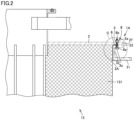
Fig. 2 is an enlarged view of an attachment region. -
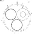
Fig. 3 is a plan view of an adsorption and desorption treatment apparatus with some adsorption and desorption members having been removed. -
Fig. 4 is an enlarged view of a C portion inFig. 2 . -
Fig. 5 is an enlarged view of an attachment region in a first embodiment. -
Fig. 6 is an enlarged view of an attachment region in a second embodiment. -
Fig. 7 is an enlarged view of an attachment region in a third embodiment. -
Fig. 8 is an enlarged view of an attachment region in a fourth embodiment. - A structure for attachment of an adsorption and desorption member in each embodiment based on the present disclosure will be described below with reference to the drawings. When the number or an amount is mentioned in an embodiment described below, the scope of the present disclosure is not necessarily limited to the number or the amount unless otherwise specified. The same or corresponding elements have the same reference characters allotted and redundant description may not be repeated. Combination of features in the embodiment as appropriate is originally intended.
-
Fig. 1 is a diagram schematically showing a construction of an organic solvent containing gas treatment system in a reference example. As shown inFig. 1 , in an adsorption anddesorption treatment apparatus 100 in an organic solvent containinggas treatment system 10, yet-to-be-treated gas A containing an organic solvent passes through a yet-to-be-treated gas line 101, and is sent by a yet-to-be-treated gas blower 102 through anadsorption gas line 103 to adsorbers 104A and 104B in an adsorption step as a result of opening and closing ofupper dampers lower dampers desorption elements - The organic solvent adsorbed to adsorption and
desorption elements respective adsorbers upper dampers lower dampers water vapor line 108 bywater vapor valves condenser 111 through a desorptionwater vapor line 110 from acondenser inlet 111A. The liquefied and condensed organic solvent is discharged through acondenser outlet 111B, sent to aseparator 113 through a condensedliquid line 112, separated intoseparated waste water 113A and anorganic solvent 113B, and recovered as a recovered solvent D. An uncondensed organic solvent incondenser 111 andseparator 113 is introduced to an upstream side of yet-to-be-treatedgas blower 102 through areturn gas line 114. - Details of adsorption and
desorption treatment apparatus 100 will be described.Fig. 2 is an enlarged view of an attachment region.Fig. 3 is a plan view of the adsorption and desorption treatment apparatus with some adsorption and desorption members having been removed.Fig. 4 is an enlarged view of a C portion inFig. 2 . Adsorption anddesorption treatment apparatus 100 includes an adsorption anddesorption member 15 provided with adsorption anddesorption elements Fig. 1 , adsorption anddesorption elements desorption elements Fig. 1 will collectively be explained as an adsorption anddesorption element 131 below. - As shown in
Figs. 2 to 4 , adsorption anddesorption member 15 includes a cylindrical adsorption anddesorption element 131 and anattachment plate 2 provided on an upper surface of adsorption anddesorption element 131 and including aflange portion 2F that extends outward from an edge of adsorption anddesorption element 131. - As shown in
Figs. 2 to 4 , adsorption anddesorption member 15 includes cylindrical adsorption anddesorption element 131 andattachment plate 2 provided on the upper surface of adsorption anddesorption element 131 and includingflange portion 2F that extends outward from the edge of adsorption anddesorption element 131. - As shown in
Figs. 2 to 4 , in an upper portion in the inside of adsorption anddesorption treatment apparatus 100, a plate-shapedmember 31, an annular erectedwall 32, and anannular plate 33 are provided, plate-shapedmember 31 being provided with threeopen holes 3A for insertion of adsorption anddesorption member 15, annular erectedwall 32 being erected upward from plate-shapedmember 31 and provided to surround an edge ofopen hole 3A,annular plate 33 extending outward from an upper end of annular erectedwall 32. Plate-shapedmember 31, annular erectedwall 32, andannular plate 33 are integrally formed by press working. Annular erectedwall 32 andannular plate 33 may be fixed to plate-shapedmember 31 by welding. -
Fig. 3 shows a state in which adsorption anddesorption member 15 is attached to one of threeopen holes 3A. Adsorption anddesorption member 15 is accommodated as being suspended in the inside of adsorption anddesorption treatment apparatus 100 by insertion of cylindrical adsorption anddesorption element 131 inopen hole 3A and layering offlange portion 2F andannular plate 33 on each other. As shown inFig. 4 , in accommodation of adsorption anddesorption element 131 in the inside of adsorption anddesorption treatment apparatuses 100, a region provided at a position whereflange portion 2F andannular plate 33 are superimposed on each other is referred to as an attachment region. The attachment region is described as anattachment region 1A with reference toFigs. 2 and4 . - As shown in
Fig. 4 ,attachment region 1A includesattachment plate 2, plate-shapedmember 31, annular erectedwall 32,annular plate 33, ahexagon head bolt 8, anut 5, and a sealingmember 6.Attachment plate 2 is provided with afirst hole portion 2a inflange portion 2F.Annular plate 33 is provided with asecond hole portion 3a. Inattachment region 1A, with ahead 8a ofhexagon head bolt 8 being placed down, ascrew portion 8b ofhexagon head bolt 8 inserted insecond hole portion 3a andfirst hole portion 2a is tightened with the use ofnut 5 from aflange portion 2F side. - For example, soft gasket can be used for sealing
member 6. Sealingmember 6 is arranged on a lower surface offlange portion 2F at a position on an adsorption anddesorption element 131 side when viewed fromhexagon head bolt 8. Sealingmember 6 is arranged annularly aroundopen hole 3A. Sealingmember 6 annularly improves hermeticity by being compressed betweenflange portion 2F andannular plate 33 at the time of attachment of adsorption anddesorption member 15. - Hermetic sealing at a position where
flange portion 2F andannular plate 33 are contiguous is thus achieved to form a leakage cut-off structure that cuts off leakage of raw gas or carrier gas from anannular plate 33 side toward theflange portion 2F side. - According to the structure for attachment of adsorption and
desorption member 15 in the reference example, the leakage cut-off structure can be formed to prevent gas leakage inattachment region 1A involved with replacement of adsorption anddesorption member 15. Therefore, uncleaned gas can be prevented from being emitted to the atmosphere and adsorption anddesorption treatment apparatus 100 can be used for a long period simply by replacement of adsorption anddesorption member 15. - The attachment region of the adsorption and desorption treatment apparatus in the organic solvent containing gas treatment system in each of a first embodiment to a fourth embodiment will be described below with reference to
Figs. 5 to 8 . A basic construction of the organic solvent containing gas treatment system and a basic construction of the adsorption and desorption treatment apparatus are the same as the constructions shown in the reference example. Differences reside in a construction of the attachment region. -
Fig. 5 is an enlarged view of an attachment region in the first embodiment. Anattachment region 1B in the first embodiment includesattachment plate 2, plate-shapedmember 31, annular erectedwall 32,annular plate 33,hexagon head bolt 8,nut 5, and sealingmember 6.Attachment plate 2 is provided withfirst hole portion 2a inflange portion 2F.Annular plate 33 is provided withsecond hole portion 3a. Inattachment region 1B, withhead 8a ofhexagon head bolt 8 being placed up,screw portion 8b ofhexagon head bolt 8 inserted infirst hole portion 2a andsecond hole portion 3a is tightened with the use ofnut 5 from theannular plate 33 side. - For example, soft gasket can be used for sealing
member 6. Sealingmember 6 is arranged on the lower surface offlange portion 2F at a position on the adsorption anddesorption element 131 side when viewed fromhexagon head bolt 8. Sealingmember 6 is arranged annularly aroundopen hole 3A. Sealingmember 6 annularly improves hermeticity by being compressed betweenflange portion 2F andannular plate 33 at the time of attachment of adsorption anddesorption member 15. - Hermetic sealing at a position where
flange portion 2F andannular plate 33 are contiguous is thus achieved to form a leakage cut-off structure that cuts off leakage of raw gas or carrier gas from theannular plate 33 side toward theflange portion 2F side. - According to the structure for attachment of adsorption and
desorption member 15 in the first embodiment, the leakage cut-off structure can be formed to prevent gas leakage inattachment region 1B involved with replacement of adsorption anddesorption member 15. Therefore, uncleaned gas can be prevented from being emitted to the atmosphere and adsorption anddesorption treatment apparatus 100 can be used for a long period simply by replacement of adsorption anddesorption member 15. -
Fig. 6 is an enlarged view of an attachment region in a second embodiment. Anattachment region 1C in the second embodiment includesattachment plate 2, plate-shapedmember 31, annular erectedwall 32,annular plate 33,hexagon head bolt 8,nut 5, and sealingmember 6.Attachment plate 2 is provided withfirst hole portion 2a inflange portion 2F.Annular plate 33 is provided with a threadedportion 3b. Inattachment region 1C, withhead 8a ofhexagon head bolt 8 being placed down,screw portion 8b ofhexagon head bolt 8 is screwed to threadedportion 3b. Then, inattachment region 1C,screw portion 8b ofhexagon head bolt 8 is inserted infirst hole portion 2a, and insertedscrew portion 8b ofhexagon head bolt 8 is tightened with the use ofnut 5 from theflange portion 2F side. - For example, soft gasket can be used for sealing
member 6. Sealingmember 6 is arranged on the lower surface offlange portion 2F at a position on the adsorption anddesorption element 131 side when viewed fromhexagon head bolt 8. Sealingmember 6 is arranged annularly aroundopen hole 3A. Sealingmember 6 annularly improves hermeticity by being compressed betweenflange portion 2F andannular plate 33 at the time of attachment of adsorption anddesorption member 15. - Hermetic sealing at a position where
flange portion 2F andannular plate 33 are contiguous is thus achieved to form a leakage cut-off structure that cuts off leakage of raw gas or carrier gas from theannular plate 33 side toward theflange portion 2F side. - According to the structure for attachment of adsorption and
desorption member 15 in the second embodiment, the leakage cut-off structure can be formed to prevent gas leakage inattachment region 1A involved with replacement of adsorption anddesorption member 15. Therefore, uncleaned gas can be prevented from being emitted to the atmosphere and adsorption anddesorption treatment apparatus 100 can be used for a long period simply by replacement of adsorption anddesorption member 15. -
Fig. 7 is an enlarged view of an attachment region in a third embodiment. Anattachment region 1D in the third embodiment includesattachment plate 2, plate-shapedmember 31, annular erectedwall 32,annular plate 33,hexagon head bolt 8,nut 5, and sealingmember 6.Attachment plate 2 is provided withfirst hole portion 2a inflange portion 2F.Annular plate 33 is provided withsecond hole portion 3a. Inattachment region 1D, withhead 8a ofhexagon head bolt 8 being placed down,screw portion 8b ofhexagon head bolt 8 inserted insecond hole portion 3a andfirst hole portion 2a is tightened with the use ofnut 5 from theflange portion 2F side. - In
attachment region 1D, a space portion D in a shape of a hollow column is provided between adsorption anddesorption element 131 and annular erectedwall 32. Raw gas or carrier gas passes through space portion D. Since a gap as large as space portion D is provided on the adsorption anddesorption element 131 side of annular erectedwall 32 as compared with the reference example, adsorption anddesorption element 131 can efficiently be used as far as a portion close toattachment plate 2. - For example, soft gasket can be used for sealing
member 6. Sealingmember 6 is arranged on the lower surface offlange portion 2F at a position on the adsorption anddesorption element 131 side when viewed fromhexagon head bolt 8. Sealingmember 6 is arranged annularly aroundopen hole 3A. Sealingmember 6 annularly improves hermeticity by being compressed betweenflange portion 2F andannular plate 33 at the time of attachment of adsorption anddesorption member 15. - Hermetic sealing at a position where
flange portion 2F andannular plate 33 are contiguous is thus achieved to form a leakage cut-off structure that cuts off leakage of raw gas or carrier gas from theannular plate 33 side toward theflange portion 2F side. - According to the structure for attachment of adsorption and
desorption member 15 in the third embodiment, the leakage cut-off structure can be formed to prevent gas leakage inattachment region 1D involved with replacement of adsorption anddesorption member 15. Therefore, uncleaned gas can be prevented from being emitted to the atmosphere and adsorption anddesorption treatment apparatus 100 can be used for a long period simply by replacement of adsorption anddesorption member 15. -
Fig. 8 is an enlarged view of an attachment region in a fourth embodiment. Anattachment region 1E in the fourth embodiment includesattachment plate 2, plate-shapedmember 31, annular erectedwall 32,annular plate 33,hexagon head bolt 8,nut 5, and sealingmember 6.Attachment plate 2 is provided withfirst hole portion 2a inflange portion 2F.Annular plate 33 is provided withsecond hole portion 3a. Inattachment region 1E, withhead 8a ofhexagon head bolt 8 being placed down,screw portion 8b ofhexagon head bolt 8 inserted insecond hole portion 3a andfirst hole portion 2a is tightened with the use ofnut 5 from theflange portion 2F side. - In
attachment region 1E, annular erectedwall 32 is in a shape extending obliquely upward from plate-shapedmember 31 towardannular plate 33. Thus, inattachment region 1E, a space portion E in a shape of a hollow frustum is provided between adsorption anddesorption element 131 and annular erectedwall 32. Raw gas or carrier gas passes through space portion E. Since a gap as large as space portion E is provided on the adsorption anddesorption element 131 side of annular erectedwall 32 as compared with the reference example, adsorption anddesorption element 131 can efficiently be used as far as a portion close toattachment plate 2. - For example, soft gasket can be used for sealing
member 6. Sealingmember 6 is arranged on the lower surface offlange portion 2F at a position on the adsorption anddesorption element 131 side when viewed fromhexagon head bolt 8. Sealingmember 6 is arranged annularly aroundopen hole 3A. Sealingmember 6 annularly improves hermeticity by being compressed betweenflange portion 2F andannular plate 33 at the time of attachment of adsorption anddesorption member 15. - Hermetic sealing at a position where
flange portion 2F andannular plate 33 are contiguous is thus achieved to form a leakage cut-off structure that cuts off leakage of raw gas or carrier gas from theannular plate 33 side toward theflange portion 2F side. - According to the structure for attachment of adsorption and
desorption member 15 in the fourth embodiment, the leakage cut-off structure can be formed to prevent gas leakage inattachment region 1E involved with replacement of adsorption anddesorption member 15. Therefore, uncleaned gas can be prevented from being emitted to the atmosphere and adsorption anddesorption treatment apparatus 100 can be used for a long period simply by replacement of adsorption anddesorption member 15. - In the embodiments, sealing
member 6 does not have to be provided. In order to facilitate positioning of sealingmember 6, an annular groove may be provided inannular plate 33. - In the embodiments, one adsorption and
desorption member 15, two adsorption anddesorption members 15, or four or more adsorption anddesorption members 15 may be provided. Adsorption anddesorption element 131 may be in a shape other than a cylindrical shape. For example, adsorption anddesorption element 131 may have a structure in a shape of a hollow quadrangular prism. In this case,attachment plate 2 should only be in a quadrangular shape also in conformity with the shape of adsorption anddesorption element 131. A plurality of attachment regions may be aligned in a quadrangular shape in a plan view. Arrangement of the attachment regions may thus be varied in conformity with the shape of adsorption anddesorption element 131. - In each embodiment above,
annular plate 33 may be provided with threadedportion 3b shown in the second embodiment. In each embodiment above,head 8a ofhexagon head bolt 8 may be arranged on theattachment plate 2 side as shown in the first embodiment. - In the embodiments, a sealing tape may be wound around a screw portion of each bolt. By winding the sealing tape, hermeticity can be enhanced and the bolt can be protected. The sealing tape is formed, for example, of a polytetrafluoroethylene material.
- It should be understood that the embodiments disclosed herein are illustrative and non-restrictive in every respect. The scope of the present disclosure is defined by the terms of the claims rather than the description above and is intended to include any modifications within the scope and meaning equivalent to the terms of the claims.
- 1A to 1E attachment region; 2 attachment plate; 2F flange portion; 2a first hole portion; 3A open hole; 3a second hole portion; 3b threaded portion; 5 nut; 6 sealing member; 8 hexagon head bolt; 8a head; 8b screw portion; 10 organic solvent containing gas treatment system; 15 adsorption and desorption member; 31 plate-shaped member; 32 annular erected wall; 33 annular plate; 100 adsorption and desorption treatment apparatus; 105A, 105B, 131 adsorption and desorption element; 101 yet-to-be-treated gas line; 102 yet-to-be-treated gas blower; 103 adsorption gas line; 104A, 104B adsorber; 106A, 106B upper damper; 107A, 107B lower damper; 108 water vapor line; 109A, 109B water vapor valve; 110 desorption water vapor line; 111 condenser; 111A cooling water pipe; 111B condenser inlet; 111C condenser outlet; 111D return gas outlet; 111E cooling water inlet; 111F cooling water outlet; 112 condensed liquid line; 113 separator; 113A separated waste water; 113B organic solvent; 113C waste liquid line; 114 return gas line; A yet-to-be-treated gas; B cleaned air; C water vapor; D recovered solvent
Claims (4)
- A structure for attachment of an adsorption and desorption member that is arranged in an adsorption and desorption treatment apparatus to adsorb and desorb an organic solvent, the adsorption and desorption treatment apparatus cleaning raw gas containing the organic solvent by separating the organic solvent from the raw gas and emitting cleaned gas and recovering the organic solvent separated from the raw gas with carrier gas, whereinin an upper portion in inside of the adsorption and desorption treatment apparatus, a plate-shaped member, an annular erected wall, and an annular plate are provided, the plate-shaped member being provided with one open hole or at least two open holes for insertion of the adsorption and desorption member, the annular erected wall being erected upward from the plate-shaped member and provided to surround an edge of the open hole, the annular plate extending outward from an upper end of the annular erected wall,the adsorption and desorption member includes a cylindrical adsorption and desorption element and an attachment plate, the attachment plate being provided on an upper surface of the adsorption and desorption element and including a flange portion that extends outward from an edge of the adsorption and desorption element,an attachment region is provided at a position where the flange portion and the annular plate are superimposed on each other when the adsorption and desorption member is accommodated in the inside of the adsorption and desorption treatment apparatus by being inserted in the open hole,the attachment region includes a hexagon head bolt and a nut,the flange portion is provided with a first hole portion,the annular plate is provided with a second hole portion, andin the attachment region, by insertion of the hexagon head bolt in the first hole portion and the second hole portion and tightening of a screw portion of the hexagon head bolt on an annular plate side with the nut to achieve hermetic sealing at a position where the flange portion and the annular plate are contiguous, a leakage cut-off structure is formed, the leakage cut-off structure cutting off leakage of raw gas or carrier gas.
- A structure for attachment of an adsorption and desorption member that is arranged in an adsorption and desorption treatment apparatus to adsorb and desorb an organic solvent, the adsorption and desorption treatment apparatus cleaning raw gas containing the organic solvent by separating the organic solvent from the raw gas and emitting cleaned gas and recovering the organic solvent separated from the raw gas with carrier gas, whereinin an upper portion in inside of the adsorption and desorption treatment apparatus, a plate-shaped member, an annular erected wall, and an annular plate are provided, the plate-shaped member being provided with one open hole or at least two open holes for insertion of the adsorption and desorption member, the annular erected wall being erected upward from the plate-shaped member and provided to surround an edge of the open hole, the annular plate extending outward from an upper end of the annular erected wall,the adsorption and desorption member includes a cylindrical adsorption and desorption element and an attachment plate, the attachment plate being provided on an upper surface of the adsorption and desorption element and including a flange portion that extends outward from an edge of the adsorption and desorption element,an attachment region is provided at a position where the flange portion and the annular plate are superimposed on each other when the adsorption and desorption member is accommodated in the inside of the adsorption and desorption treatment apparatus by being inserted in the open hole,the attachment region includes a bolt and a nut,the flange portion is provided with a hole portion,the annular plate is provided with a threaded portion, andin the attachment region, by tightening with the nut, of the bolt screwed to the threaded portion and inserted in the hole portion to achieve hermetic sealing at a position where the flange portion and the annular plate are contiguous, a leakage cut-off structure is formed, the leakage cut-off structure cutting off leakage of raw gas or carrier gas.
- The structure for attachment of an adsorption and desorption member according to claim 1 or 2, whereinin the attachment region, a space portion in a shape of a hollow column or a hollow frustum is provided between the adsorption and desorption element and the annular erected wall, andraw gas or carrier gas passes through the space portion.
- The structure for attachment of an adsorption and desorption member according to any one of claims 1 to 3, wherein
the leakage cut-off structure includes a sealing member on a lower surface of the flange portion at a position on a side of the adsorption and desorption element when viewed from the nut.
Applications Claiming Priority (2)
| Application Number | Priority Date | Filing Date | Title |
|---|---|---|---|
| JP2021145153 | 2021-09-07 | ||
| PCT/JP2022/033000 WO2023037965A1 (en) | 2021-09-07 | 2022-09-01 | Attachment structure for adsorption-desorption member |
Publications (1)
| Publication Number | Publication Date |
|---|---|
| EP4400199A1 true EP4400199A1 (en) | 2024-07-17 |
Family
ID=85506676
Family Applications (1)
| Application Number | Title | Priority Date | Filing Date |
|---|---|---|---|
| EP22867287.9A Withdrawn EP4400199A1 (en) | 2021-09-07 | 2022-09-01 | Attachment structure for adsorption-desorption member |
Country Status (7)
| Country | Link |
|---|---|
| US (1) | US20240375035A1 (en) |
| EP (1) | EP4400199A1 (en) |
| JP (1) | JPWO2023037965A1 (en) |
| KR (1) | KR20240052818A (en) |
| CN (1) | CN117916006A (en) |
| TW (1) | TW202325381A (en) |
| WO (1) | WO2023037965A1 (en) |
Families Citing this family (1)
| Publication number | Priority date | Publication date | Assignee | Title |
|---|---|---|---|---|
| WO2022054733A1 (en) * | 2020-09-11 | 2022-03-17 | 東洋紡株式会社 | Organic solvent recovery system |
Family Cites Families (15)
| Publication number | Priority date | Publication date | Assignee | Title |
|---|---|---|---|---|
| US2096851A (en) * | 1934-06-13 | 1937-10-26 | Bullard Co | Air purifier |
| US4204846A (en) * | 1978-05-26 | 1980-05-27 | Donaldson Company, Inc. | Self-cleaning air filter |
| US4445912A (en) * | 1982-02-04 | 1984-05-01 | The Mike Volk Co., Inc. | Effluent air filtration apparatus |
| US4522717A (en) * | 1983-06-24 | 1985-06-11 | Brust John E | Filter apparatus |
| JPS60189318U (en) * | 1984-05-23 | 1985-12-14 | 東洋紡績株式会社 | Switching damper device in waste gas adsorption purification equipment |
| JPH072029Y2 (en) * | 1990-02-20 | 1995-01-25 | 大阪瓦斯株式会社 | Gas adsorption element |
| JPH086488Y2 (en) * | 1990-08-15 | 1996-02-28 | 大阪瓦斯株式会社 | Solvent recovery device |
| JP2542538Y2 (en) * | 1991-10-24 | 1997-07-30 | 大阪瓦斯株式会社 | Adsorption tower |
| JPH0685020U (en) * | 1992-12-07 | 1994-12-06 | 石川島播磨重工業株式会社 | Dust filter |
| EP0781585B9 (en) * | 1995-12-29 | 2003-09-03 | Glatt Gmbh | Apparatus for dedusting a gas |
| US6921423B2 (en) * | 2003-07-21 | 2005-07-26 | Ingersoll-Rand Company | Separator tank assembly and method of manufacture |
| US8646534B2 (en) * | 2011-05-23 | 2014-02-11 | Richard R. Magden | Well head containment fitting device |
| KR102648977B1 (en) | 2018-11-12 | 2024-03-20 | 엘지디스플레이 주식회사 | Organic Light Emitting Display |
| CN211098282U (en) | 2019-04-29 | 2020-07-28 | 东洋纺株式会社 | recycling system |
| CN212327833U (en) | 2019-12-11 | 2021-01-12 | 东洋纺株式会社 | Recycling devices and recycling systems |
-
2022
- 2022-09-01 JP JP2022577657A patent/JPWO2023037965A1/ja active Pending
- 2022-09-01 CN CN202280060458.9A patent/CN117916006A/en active Pending
- 2022-09-01 US US18/689,174 patent/US20240375035A1/en active Pending
- 2022-09-01 EP EP22867287.9A patent/EP4400199A1/en not_active Withdrawn
- 2022-09-01 WO PCT/JP2022/033000 patent/WO2023037965A1/en not_active Ceased
- 2022-09-01 KR KR1020247010648A patent/KR20240052818A/en active Pending
- 2022-09-06 TW TW111133627A patent/TW202325381A/en unknown
Also Published As
| Publication number | Publication date |
|---|---|
| TW202325381A (en) | 2023-07-01 |
| KR20240052818A (en) | 2024-04-23 |
| JPWO2023037965A1 (en) | 2023-03-16 |
| US20240375035A1 (en) | 2024-11-14 |
| WO2023037965A1 (en) | 2023-03-16 |
| CN117916006A (en) | 2024-04-19 |
Similar Documents
| Publication | Publication Date | Title |
|---|---|---|
| US6551387B2 (en) | Gas separation apparatus | |
| JPH0235909Y2 (en) | ||
| US20240375035A1 (en) | Structure for attachment of adsorption and desorption member | |
| EP4400198A1 (en) | Structure for attaching adsorption-desorption member | |
| AU691058B2 (en) | Pressure swing adsorption process for fractionating a multi-component mixture | |
| KR20170001486U (en) | Purifying Apparatus for Chimney of Industry | |
| JP4575673B2 (en) | Gasoline vapor recovery method and recovery device | |
| JP5440971B2 (en) | Compressed air dehumidification system | |
| JP5109028B2 (en) | Method for purifying a large amount of exhaust gas containing lean volatile hydrocarbons | |
| KR102796504B1 (en) | Mobile volatile organic compound recovery device and method | |
| JP4538622B2 (en) | Gas separator | |
| KR100266479B1 (en) | Adsorptive collection and recovery of volatile petroleum compounds | |
| CN213492849U (en) | Active carbon box for adsorbing VOCs | |
| JP4911139B2 (en) | Removal and recovery of volatile organic compounds | |
| JP4973817B2 (en) | Removal and recovery of volatile organic compounds | |
| CN108654234A (en) | A kind of air pollution control device and its application method | |
| JPWO2023037965A5 (en) | ||
| JP6058404B2 (en) | Radioactive material adsorption equipment | |
| CN219744380U (en) | Adsorption energy-saving device for zeolite molecular sieve | |
| CN215610373U (en) | Multistage grading tandem type adsorption and vacuum desorption waste gas recovery and treatment device | |
| KR102450032B1 (en) | High-efficiency oil vapor liquefaction recovery device capable of removing static electricity | |
| CN214503528U (en) | Pollution source waste gas monitoring device | |
| CN221536211U (en) | Waste gas treatment and purification device for vulcanization workshop | |
| CN211963476U (en) | Chemical plant flue gas desulfurization denitration dust collecting equipment | |
| KR20180098067A (en) | Oxygen generator |
Legal Events
| Date | Code | Title | Description |
|---|---|---|---|
| STAA | Information on the status of an ep patent application or granted ep patent |
Free format text: STATUS: THE INTERNATIONAL PUBLICATION HAS BEEN MADE |
|
| PUAI | Public reference made under article 153(3) epc to a published international application that has entered the european phase |
Free format text: ORIGINAL CODE: 0009012 |
|
| STAA | Information on the status of an ep patent application or granted ep patent |
Free format text: STATUS: REQUEST FOR EXAMINATION WAS MADE |
|
| 17P | Request for examination filed |
Effective date: 20240328 |
|
| AK | Designated contracting states |
Kind code of ref document: A1 Designated state(s): AL AT BE BG CH CY CZ DE DK EE ES FI FR GB GR HR HU IE IS IT LI LT LU LV MC MK MT NL NO PL PT RO RS SE SI SK SM TR |
|
| DAV | Request for validation of the european patent (deleted) | ||
| DAX | Request for extension of the european patent (deleted) | ||
| STAA | Information on the status of an ep patent application or granted ep patent |
Free format text: STATUS: THE APPLICATION HAS BEEN WITHDRAWN |
|
| 18W | Application withdrawn |
Effective date: 20250120 |