EP4399424B1 - Gangschaltungsaktuator - Google Patents
Gangschaltungsaktuator Download PDFInfo
- Publication number
- EP4399424B1 EP4399424B1 EP22716156.9A EP22716156A EP4399424B1 EP 4399424 B1 EP4399424 B1 EP 4399424B1 EP 22716156 A EP22716156 A EP 22716156A EP 4399424 B1 EP4399424 B1 EP 4399424B1
- Authority
- EP
- European Patent Office
- Prior art keywords
- cam
- central rod
- barrel cam
- barrel
- axial direction
- Prior art date
- Legal status (The legal status is an assumption and is not a legal conclusion. Google has not performed a legal analysis and makes no representation as to the accuracy of the status listed.)
- Active
Links
Images


Classifications
-
- F—MECHANICAL ENGINEERING; LIGHTING; HEATING; WEAPONS; BLASTING
- F16—ENGINEERING ELEMENTS AND UNITS; GENERAL MEASURES FOR PRODUCING AND MAINTAINING EFFECTIVE FUNCTIONING OF MACHINES OR INSTALLATIONS; THERMAL INSULATION IN GENERAL
- F16H—GEARING
- F16H61/00—Control functions within control units of change-speed- or reversing-gearings for conveying rotary motion ; Control of exclusively fluid gearing, friction gearing, gearings with endless flexible members or other particular types of gearing
- F16H61/26—Generation or transmission of movements for final actuating mechanisms
- F16H61/28—Generation or transmission of movements for final actuating mechanisms with at least one movement of the final actuating mechanism being caused by a non-mechanical force, e.g. power-assisted
- F16H61/32—Electric motors , actuators or related electrical control means therefor
-
- F—MECHANICAL ENGINEERING; LIGHTING; HEATING; WEAPONS; BLASTING
- F16—ENGINEERING ELEMENTS AND UNITS; GENERAL MEASURES FOR PRODUCING AND MAINTAINING EFFECTIVE FUNCTIONING OF MACHINES OR INSTALLATIONS; THERMAL INSULATION IN GENERAL
- F16H—GEARING
- F16H63/00—Control outputs from the control unit to change-speed- or reversing-gearings for conveying rotary motion or to other devices than the final output mechanism
- F16H63/02—Final output mechanisms therefor; Actuating means for the final output mechanisms
- F16H63/08—Multiple final output mechanisms being moved by a single common final actuating mechanism
- F16H63/16—Multiple final output mechanisms being moved by a single common final actuating mechanism the final output mechanisms being successively actuated by progressive movement of the final actuating mechanism
- F16H63/18—Multiple final output mechanisms being moved by a single common final actuating mechanism the final output mechanisms being successively actuated by progressive movement of the final actuating mechanism the final actuating mechanism comprising cams
-
- F—MECHANICAL ENGINEERING; LIGHTING; HEATING; WEAPONS; BLASTING
- F16—ENGINEERING ELEMENTS AND UNITS; GENERAL MEASURES FOR PRODUCING AND MAINTAINING EFFECTIVE FUNCTIONING OF MACHINES OR INSTALLATIONS; THERMAL INSULATION IN GENERAL
- F16H—GEARING
- F16H63/00—Control outputs from the control unit to change-speed- or reversing-gearings for conveying rotary motion or to other devices than the final output mechanism
- F16H63/02—Final output mechanisms therefor; Actuating means for the final output mechanisms
- F16H63/30—Constructional features of the final output mechanisms
- F16H63/304—Constructional features of the final output mechanisms the final output mechanisms comprising elements moved by electrical or magnetic force
-
- F—MECHANICAL ENGINEERING; LIGHTING; HEATING; WEAPONS; BLASTING
- F16—ENGINEERING ELEMENTS AND UNITS; GENERAL MEASURES FOR PRODUCING AND MAINTAINING EFFECTIVE FUNCTIONING OF MACHINES OR INSTALLATIONS; THERMAL INSULATION IN GENERAL
- F16H—GEARING
- F16H61/00—Control functions within control units of change-speed- or reversing-gearings for conveying rotary motion ; Control of exclusively fluid gearing, friction gearing, gearings with endless flexible members or other particular types of gearing
- F16H61/26—Generation or transmission of movements for final actuating mechanisms
- F16H61/28—Generation or transmission of movements for final actuating mechanisms with at least one movement of the final actuating mechanism being caused by a non-mechanical force, e.g. power-assisted
- F16H2061/2869—Cam or crank gearing
-
- F—MECHANICAL ENGINEERING; LIGHTING; HEATING; WEAPONS; BLASTING
- F16—ENGINEERING ELEMENTS AND UNITS; GENERAL MEASURES FOR PRODUCING AND MAINTAINING EFFECTIVE FUNCTIONING OF MACHINES OR INSTALLATIONS; THERMAL INSULATION IN GENERAL
- F16H—GEARING
- F16H63/00—Control outputs from the control unit to change-speed- or reversing-gearings for conveying rotary motion or to other devices than the final output mechanism
- F16H63/02—Final output mechanisms therefor; Actuating means for the final output mechanisms
- F16H63/30—Constructional features of the final output mechanisms
- F16H63/304—Constructional features of the final output mechanisms the final output mechanisms comprising elements moved by electrical or magnetic force
- F16H2063/3056—Constructional features of the final output mechanisms the final output mechanisms comprising elements moved by electrical or magnetic force using cam or crank gearing
-
- F—MECHANICAL ENGINEERING; LIGHTING; HEATING; WEAPONS; BLASTING
- F16—ENGINEERING ELEMENTS AND UNITS; GENERAL MEASURES FOR PRODUCING AND MAINTAINING EFFECTIVE FUNCTIONING OF MACHINES OR INSTALLATIONS; THERMAL INSULATION IN GENERAL
- F16H—GEARING
- F16H63/00—Control outputs from the control unit to change-speed- or reversing-gearings for conveying rotary motion or to other devices than the final output mechanism
- F16H63/02—Final output mechanisms therefor; Actuating means for the final output mechanisms
- F16H63/30—Constructional features of the final output mechanisms
- F16H63/32—Gear shift yokes, e.g. shift forks
- F16H2063/321—Gear shift yokes, e.g. shift forks characterised by the interface between fork body and shift rod, e.g. fixing means, bushes, cams or pins
Definitions
- Gear shift actuators are utilized in motor vehicles to shift transmission between two coaxially disposed, rotary shafts between a gear engaged position in which rotary engagement between the two shafts is established and torque transmission takes place, and a neutral, disengaged position, in which the two rotary shafts are decoupled from each other.
- a typical case of application for a gear shift actuator of the above-described type is an actuator for a dog clutch.
- a dog clutch is a mechanism for connecting and disconnecting two rotating shafts. It is based on the working principle to make a set of regularly spaced teeth or protrusions on one wheel connected to one of the shafts to a set of complementary recesses between teeth on another wheel connected to second shaft.
- gear shift actuators For such gear shift actuators the situation may arise that the two teeth or dog wheels are in a relative angular position with respect to each other such that the teeth of one wheel are facing directly opposite teeth of the other wheel, in which case the gear shift actuator cannot shift to the gear engaged position until the dog wheels have rotated relative to each other so that the dogs of one wheel are aligned with recesses between dogs of the other wheel.
- FR 2 912 795 A1 discloses a transmission actuator having a sleeve which is supported to be rotatable about an axis but fixed in axial direction.
- a barrel cam for driving a shift fork is movable in axial direction and comprises a helical groove which is engaged by a component that rotates with the sleeve, whereby rotation of the sleeve is translated into axial movement of the barrel cam, which axial movement is transmitted to the shift fork.
- DE 10 2014 003238 A1 discloses a manual transmission in which in a similar manner the relative rotational movement of a barrel cam about an axis and a cam follower engaging with a helical cam track portion of the barrel cam is translated into axial movement.
- the rotary member comprises a hollow cylindrical sleeve which is provided with a first cam follower projecting inwardly from an inner wall of the sleeve.
- the driven component comprises a first barrel cam which has a helical cam groove in its outer wall configured to receive the first cam follower.
- the first barrel cam is supported in the sleeve by a central rod to be slidably moveable in the sleeve along the central rod in axial direction but to be locked against rotational movements around the axial direction with respect to the central rod.
- the central rod in turn is supported in the housing to be moveable in axial direction but to be locked against rotational movements around the axial direction with respect to the housing.
- this gear shift actuator is asymmetric in that the movement of the first barrel cam, when moving in the first direction to move a shift fork from neutral to a first gear, is transmitted to the compression mechanism and from the compression mechanism (via the second end stop) further to the central rod, whereas movement of the first barrel cam in the opposite second direction to move a shift fork back from the first gear to the neutral position is transmitted from the first barrel cam directly (i.e. not via the compression mechanism) via the first end stop to the central rod.
- the central rod is acting in a compliant or yielding manner when it is moved in the first direction to move from neutral to first gear which means that, when the shift fork is blocked, the movement of the first barrel cam is absorbed by the compression mechanism which thereby is compressed and stores the actuation force without further moving the central rod; once the blocked state of the shift fork is released the expanding movement of the compression mechanism moves the central rod to shift a shift fork to the first gear engaged position.
- the central rod is driven in a stiff or direct contact manner by the first barrel cam which exerts force directly via the first end stop of the central rod.
- the compression mechanism biases the first barrel cam towards the first end stop and the second barrel cam towards the second end stop on the central rod.
- the sleeve is provided with a second cam follower which is disposed circumferentially aligned in the sleeve with the first cam follower and which is received in a helical cam groove of the second barrel cam.
- Each of the helical cam grooves extends about 180° around the circumference of the respective barrel cam, whereas the remaining circumferential portion of the surface of the respective one of the first and second barrel cams is a recessed portion such that the respective one of the first and second cam followers is free to move in the recessed portion in axial direction when it is located in the associated recessed portion.
- the helical cam grooves of the first and second barrel cams are in rotational direction offset by 180° with respect to each other such that, when the first cam follower is engaged in the cam groove of the first barrel cam, the second cam follower is located in the recessed portion of the second barrel cam, so that, when the central rod is in the position corresponding to the neutral position of a coupled shift fork, rotation of the sleeve in the second sense of rotation moves the second barrel cam in the second direction, which movement is transmitted through the compression mechanism (via the first barrel cam and the first end stop) to the central rod to drive a coupled shift fork from neutral towards a second gear engaged position, and such that, when the central rod is in the position corresponding to the second gear engaged position of a coupled shift fork, rotation of the sleeve in the first sense of rotation moves the second barrel cam in the first direction, which movement is transmitted via the second end stop to the central rod directly to drive a coupled shift fork from the second gear engaged position back to the neutral position.
- the actuation characteristic for the movement from a neutral position to a second gear engaged position of a coupled shift fork is asymmetric in the sense that the actuating movement of the central rod to move a coupled shift fork from neutral into the second gear engaged position is compliant and capable of absorbing actuating movement of the second barrel cam by compression of the compression mechanism in case the shift fork is blocked, wherein the compression of the compression mechanism provides the driving force for completing the movement of the shift fork into the second gear engaged position as soon as the blocked state is released, whereas the actuating movement of the second barrel cam in the opposite direction to move a coupled shift fork from the second gear engaged position to the neutral position is transmitted (via the second end stop) directly to the central rod so that force is transmitted in a stiff manner to the central rod when moving a coupled shift fork from the second gear engaged position back to neutral.
- the actuation characteristics of the second barrel cam movement are symmetrical to the actuation movements of the first barrel cam as described above.
- the compression mechanism comprises a compression spring extending in the axial direction from the first barrel cam along the central rod in the direction towards the second end stop on the central rod remote from the first barrel cam to bias the second end stop away from the first barrel cam.
- the central rod has a non-circular cross-sectional shape and each of the first and second barrel cams has an opening of complementary cross-sectional shape such that the central rod, when it is received in the openings of the first and second barrel cams, allows sliding movement of the first and second barrel cams in axial direction, but locks the first and second barrel cams against rotational movements around the axial direction.
- the non-circular cross-sectional shape can for example be formed by any kind of keyed surface of the central rod, for example a planar surface portion which is in abutment on a complementary planar surface portion in the openings of the barrel cams.
- the compression mechanisms and a sliding resistance of the first barrel cam for axial movements on the central rod are arranged such that the first barrel cam starts moving and starts to compress the compression mechanism once a predetermined threshold force is acting between the first barrel cam and the central rod. In this manner it is achieved that the first barrel cam is held on the central rod in a manner that is not too spongy, whereas the barrel cam is able to react and to move with respect to the central rod when the central rod is blocked by a substantial counter-force.
- the second barrel cam has the same shape as the first barrel cam but is oppositely oriented in axial direction with respect to the first barrel cam such that two corresponding end surfaces including the recessed portions of the first and second barrel cams are facing each other, wherein the second barrel cam is disposed rotated by 180° around the axial direction relative to the first barrel cam.
- the helical cam grooves of the first and second barrel cam have the same shape and arrangement on the respective barrel cams to and cooperate with the respective one of the first and second cam followers in a symmetric manner for the first and second barrel cams.
- Fig. 9 shows a schematic, partially cross-sectional view of a gear shift actuator capable of shifting a coupled shift fork 50 from a neutral position N to a first gear engaged position and back again to neutral position.
- the gear shift actuator comprises a rotary member in the form of a cylindrical, hollow sleeve 4 which is driven by an electric motor (not shown) to rotate selectively in a first sense of rotation and in an opposed second sense of rotation.
- the cylindrical sleeve 4 is supported in a housing (not shown) of the actuator to be rotatable about a rotational axis of the sleeve 4 defining an axial direction, wherein the sleeve 4 is supported such that it is unmovable in the axial direction with respect to the housing.
- the sleeve 4 is provided with a first cam follower 6 projecting radially inwardly from an inner wall of the sleeve.
- the first cam follower 6 is shown as a short cylindrical pin.
- the gear shift actuator further comprises a first barrel cam 10 which also is generally cylindrical and which is received in the interior of the sleeve 4.
- the barrel cam 10 is supported by a central rod 30 extending inside of the sleeve 4 in the axial direction and projecting from the sleeve 4 to be coupled to a shift fork 50.
- the central rod 30 is received in an opening of the first barrel cam 10, wherein the cross-sectional shape of the central rod is non-circular, and the cross-sectional shape of the opening of the first barrel cam 10 has a complementary non-circular shape such that the barrel cam 10 may slide along the central rod 30 in axial direction, whereas it is locked against rotational movements around the rotational axis of the sleeve 4.
- the actuation characteristic of the gear shift actuator shown in Fig. 9 is compliant or yielding when the gear shift actuator attempts to move a coupled shift fork 50 from neutral to the first gear engaged position, whereas there is a direct non-yielding force transfer from the first barrel cam 10 to the central rod 30 and the coupled shift fork 50 when it is moved back from the first gear engaged position to the neutral position.
- gear shift actuator which is capable of moving a coupled shift fork from neutral in a first direction to a first gear engaged position, and from neutral in an opposite second direction to a second gear engaged position, wherein in both directions the actuation is compliant or yielding when moving from neutral to the gear engaged position, whereas a direct, stiff force transmission is effected when moving back from one of the in gear engaged positions to the neutral position.
- Fig. 1 shows a cross-sectional view of this embodiment which comprises a hollow, cylindrical sleeve 4 which is rotatably supported in a housing of the gear shift actuator, but unmovably supported with respect to movements in axial direction defined by the rotary axis of the sleeve 4.
- ball bearings are shown at both ends of the sleeve 4 to rotatably support it.
- a central rod 30 is extending within the sleeve and protruding from the sleeve and the housing of the gear shift actuator.
- the central rod 30 supports a first barrel cam 10 and a second barrel cam 20 which are slidably supported on the central rod, but locked against rotational movements with respect to the central rod around the axial direction.
- the central rod 30 is supported to be moveable in axial direction, but rotational movements around an axis parallel to the axial direction are blocked.
- Movement of the first barrel cam 10 to the left hand side is limited by a first end stop 32 fixed on the central rod 30, and movement of the second barrel cam 20 to the right hand side is limited by a second end stop 34 fixed to the central rod 30.
- a compression mechanism 40 here in the form a compression spring, is acting which urges the first barrel cam 10 towards the first end stop 32 and the second barrel cam 20 towards the second end stop 34.
- Fig. 2 shows a schematic perspective view of the main components of the gear shift actuator, wherein the outer sleeve 4 is illustrated by dashed lines in a transparent manner to make the interior of the sleeve visible.
- a central rod 30 extends, which at one end projects beyond the sleeve 4 (and in fact also protrudes from the housing of the gear shift actuator as shown in Fig. 1 ).
- the central rod 30 supports the first and second barrel cams 10, 20 within the interior of the sleeve 4, wherein the first and second barrel cams are slidable in axial direction along the central rod 30, but locked against rotational movements around the axial direction with respect to the central rod.
- the first barrel cam 10 is provided with a helical cam groove 12 formed in the surface of the first barrel cam 10 and extending about 180° around the circumference of the first barrel cam.
- the second barrel cam 20 is provided with a helical cam groove 22 extending about 180° around the circumference of the second barrel cam 20, wherein in the view of Fig. 2 only the beginning or entry of the cam groove 22 is visible and the remaining portion is not visible because it is on a backside of the second barrel cam 20.
- the remaining circumferential surface portion beyond the cam groove 22 of the second barrel cam is a recessed portion 24.
- the first barrel cam 10 is likewise provided with a recessed portion 14 in its circumferential portion beyond the first cam groove 12.
- the sleeve 4 is provided with a first cam follower 6 and a second cam follower 8 which are projecting from the inner wall of the sleeve to extend to a certain extent radially inwards within the sleeve.
- the first cam follower 6 is shown in Fig. 2 as a flat pin at the entry to the cam groove 12 of the first barrel cam 10, and the second cam follower 8 is in this state at the opposite entry to the cam groove 22 of the second barrel cam 20.
- first cam follower 6 slides from the entry point of the cam groove 12 further along the cam groove 12 which causes an axial movement of the first barrel cam 10 in a direction to the left hand side, whereas at the same time the second cam follower 8 is leaving the entry to its associated cam groove 22 and enters the recessed portion 24 of the second barrel cam 20.
- first and second barrel cams 6, 8 are, except for a small angular movement range around the position shown in Fig. 2 and 3 , where both cam follower 6, 8 are at the entries to their associated cam grooves 12, 22, the positioning of the first and second cam grooves 6, 8 is alternating, i.e.
- the second cam follower 8 when the first cam follower 6 is engaged in the cam groove 12 of the first barrel cam 10, the second cam follower 8 is in the recessed portion 24 of the second barrel cam 20 which therefore is able to perform sliding movement along the central rod 30 because the second cam follower 8 is free to move in axial direction relative to the recessed portion 24 of the second barrel cam, whereas when the second cam follower 20 is engaged within its associated cam groove 22 the first cam follower 6 has reached the recessed portion 14 of the first barrel cam 10 such that the first barrel cam is capable of sliding in axial direction on the central rod 30 relative to the sleeve 4 because the first cam follower 6 is free to axially move within the recessed portion 14 of the first barrel cam 10.
- the gear shift actuator is shown with a position of the central rod 30 in which a coupled shift fork 50 is in a neutral position. If the sleeve 4 is now rotated in a first sense of rotation such that the first cam follower 6 is moved to slide along the cam groove 12 about 180° to an opposite end of the cam groove 12 (this end point of the movement is shown in Fig. 4 ) the first barrel cam 10 is moved in axial direction in a first direction illustrated by arrow 1, to the left hand side to reach the positioning shown in Fig. 4 .
- shift fork 50 coupled to the central rod is free to move this movement of the first barrel cam 10 in the first direction 1 is transmitted through the compression mechanism 40 to the second barrel cam 20 which is therefore likewise axially moved to drive the central rod 30 via the second end stop 34, which movement of the central rod 30 is transferred to the shift fork 50 which is therefore moved to the first gear engaged position shown in Fig. 4 .
- Figs. 5 and 6 illustrate the same rotational movement step of the sleeve 4 in the situation when the shift fork 50 coupled to the central rod 30 is blocked.
- the first barrel cam 10 has been driven to make the same axial movement in the first direction 1 to the left hand side as in Fig. 4 , but since the central rod 30 was blocked by the blocked shift fork 50 the axial movement of the first barrel cam 10 in the first direction could not be transmitted to the second barrel cam 22 which was therefore moved in a sliding manner relative to the central rod 30, thereby compressing the compression mechanism 40 between the first and second barrel cams 10, 20.
- the second barrel cam 20 is axially driven in the second direction of arrow 2 relative to the sleeve 4 which movement is transmitted by the central rod 30 to the coupled shift fork 50 to move it from neutral to the second gear engaged position.
- the shift fork 50 is blocked while the sleeve 4 is rotated in the second sense of rotation to move the second barrel cam 20 in the second direction 2
- the second barrel has 20 to move axially relative to the central rod 40, which central rod is blocked by the blocked shift fork 50, whereby the movement of the second barrel cam 20 in the second direction 2 to the right hand side compresses the compression mechanism 40. If the compression mechanism 40 has been brought to the compressed state and the blocked state of the shift fork 50 ends the force released by the expanding compression mechanism will pull the central rod 30 in the second direction 2 to bring the coupled shift fork 50 from the neutral position to the second gear engaged position.
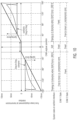
- Fig. 10 illustrates the actuation characteristics of the above-described embodiment of Figs. 1 to 8 .
- Fig. 10 shows the linear displacement of the central rod of the gear shift actuator in axial direction (indicated by the full line) as a function of the rotation angle of the sleeve 4 relative to the first and second cam barrels. There is a small angular range around 0° where there is no displacement as a function of the turning angle of the sleeve (horizontal part of the full line). This is due to the fact that in the state as illustrated in Fig.
- Fig. 10 Also illustrated in Fig. 10 is the blocked shift fork situation, indicated in the areas “scenario dog to dog", which means that the shift fork is unable to move into the position corresponding to engagement because there is dog to dog opposition of the two parts to be engaged which prevents engagement.
- the movement state of the central rod is illustrated by the dashed line which at the beginning is extending essentially horizontally because the central rod is blocked.
- the spring force shown in full line in the superimposed diagrams showing the spring force as a function of turning angle
- the central rod is also in the case of a blocked shift fork first moving in axial direction over a certain distance until its movement is blocked by the shift fork.
- the reason is on the one hand that the coupling of the central rod to the shift fork is such that the central rod first has to move towards the shift fork until a force transmitting contact is established at the interface between central rod and shift fork.
- the two parts to be engaged have first to be moved relative towards to each other until their respective dogs have been moved into the same plane so that a blocking situation may arise.
Landscapes
- Engineering & Computer Science (AREA)
- General Engineering & Computer Science (AREA)
- Mechanical Engineering (AREA)
- Gear-Shifting Mechanisms (AREA)
Claims (6)
- Gangschaltungsaktuator mit einem Linearantriebsaufbau, der ein Drehteil, das in einem Gehäuse drehbar, aber unbeweglich in einer axialen Richtung, die durch seine Drehachse definiert ist, gelagert ist, einen Elektromotor zum Drehen des Drehteils und eine angetriebene Komponente aufweist, die mit dem Drehteil in Eingriff steht, um Drehbewegung des Drehteils in lineare Bewegung der angetriebenen Komponente entlang der axialen Richtung umzusetzen, um eine Schaltgabel (50) aus einer neutralen Stellung in eine erster-Gang-eingelegt-Stellung und zurück zur neutralen Stellung anzutreiben, wenn das Drehteil zur Drehung in einem ersten Drehsinn und in einem zweiten Drehsinn entgegengesetzt dem ersten Drehsinn angetrieben wird, dadurch gekennzeichnet, dassdas Drehteil eine hohle, zylindrische Hülse (4) aufweist, die mit einem ersten Nockenfolger (6) versehen ist, der von einer Innenwand der Hülse (4) nach innen vorsteht,die angetriebene Komponente eine erste Nockentrommel (10) aufweist, die in ihrer Außenwand eine schraubenförmige Nockennut (12), die dazu ausgestaltet ist, den ersten Nockenfolger (6) aufzunehmen, hat und die in der Hülse (4) durch eine zentrale Stange (30) gelagert ist, um in der Hülse gleitend beweglich entlang der zentralen Stange (30) in axialer Richtung zu sein, aber gesperrt gegenüber Drehbewegungen um die axiale Richtung in Bezug auf die zentrale Stange (30) zu sein,die zentrale Stange (30) im Gehäuse gelagert ist, um in axialer Richtung beweglich zu sein, aber gesperrt gegenüber Drehbewegungen um die axiale Richtung zu sein, und einen zweiten Endanschlag (34) trägt, der damit in einem Abstand zum ersten Trommelnocken (10) verbunden ist, wobei die zentrale Stange (30) dazu ausgestaltet ist, aus dem Gehäuse vorzustehen und mit einer Schaltgabel gekoppelt zu werden, um diese anzutreiben,ein Kompressionsmechanismus (40) dazu ausgestaltet ist, die zentrale Stange (30) aus dem ersten Trommelnocken (10) herauszudrücken, indem der zweite Endanschlag (34) in Richtung weg von dem ersten Trommelnocken (10) vorgespannt ist, wobei die vorgespannte Bewegung der zentralen Stange (30) begrenzt wird durch einen ersten Endanschlag (32) an der zentralen Stange (30), der in Anlage an den ersten Trommelnocken (10) kommt, unddie schraubenförmige Nockennut so ausgestaltet ist, dass Drehung der Hülse (4) im ersten Drehsinn den ersten Trommelnocken (10) axial in einer ersten Richtung bewegt, wobei diese Bewegung über den Kompressionsmechanismus (40) auf die zentrale Stange (30) übertragen wird, um eine gekoppelte Schaltgabel (50) aus der neutralen Stellung in die erster-Gang-eingelegt-Stellung anzutreiben, und so dass die Drehung der Hülse im zweiten Drehsinn den ersten Trommelnocken in eine entgegengesetzte zweite Richtung bewegt, wobei diese Bewegung auf die zentrale Stange (30) übertragen wird, um eine gekoppelte Schaltgabel (50) aus der erster-Gang-eingelegt-Stellung in die neutrale Stellung anzutreiben.
- Gangschaltungsaktuator nach Anspruch 1, dadurch gekennzeichnet, dasszwischen dem zweiten Endanschlag (34) und dem Kompressionsmechanismus (40) ein zweiter Trommelnocken (20) an der zentralen Stange (30) gelagert ist, um axial beweglich, aber gesperrt gegenüber Drehbewegung um die axiale Richtung in Bezug auf die zentrale Stange zu sein, wobei der zweite Trommelnocken (20) durch den Kompressionsmechanismus (40) zum zweiten Endanschlag (34) hin vorgespannt ist,die Hülse (4) mit einem zweiten Nockenfolger (8) versehen ist, der in Umfangsrichtung mit dem ersten Nockenfolger (6) ausgerichtet ist und der in einer schraubenförmigen Nockennut (22) des zweiten Trommelnockens (20) aufgenommen ist,jede der schraubenförmigen Nockennuten (12, 22) in Umfangsrichtung etwa 180° ausgedehnt ist, wohingegen der übrige Umfangsbereich der Oberfläche des jeweiligen Trommelnockens ein vertiefter Bereich (12, 24) ist, so dass der jeweilige Nockenfolger (6, 8) frei ist, sich in dem vertieften Bereich (14, 24) in axialer Richtung zu bewegen,die schraubenförmigen Nockennuten (12, 22) der ersten und zweiten Trommelnocken (10, 20) in Drehrichtung um 180° versetzt zueinander sind, so dass, wenn der erste Nockenfolger (6) in die Nockennut (12) des ersten Trommelnockens (10) eintritt, der zweite Nockenfolger (8) seine Nockennut verlässt und in den vertieften Bereich (24) des zweiten Trommelnockens (20) eintritt, so dass, wenn die zentrale Stange (30) in der Stellung ist, die der neutralen Stellung einer gekoppelten Schaltgabel entspricht, die Drehung der Hülse (4) im zweiten Drehsinn den zweiten Trommelnocken (20) in die zweite Richtung (2) bewegt, wobei diese Bewegung durch den Kompressionsmechanismus (40) auf die zentrale Stange (30) übertragen wird, um eine gekoppelte Schaltgabel (50) aus der neutralen Stellung in eine zweiter-Gang-eingelegt-Stellung anzutreiben, und so dass, wenn die zentrale Stange (30) in der Stellung ist, die der zweiter-Gang-eingelegt-Stellung einer gekoppelten Schaltgabel entspricht, die Drehung der Hülse (4) im ersten Drehsinn den zweiten Trommelnocken (20) in die erste Richtung (1) bewegt, wobei diese Bewegung auf die zentrale Stange (30) übertragen wird, um eine gekoppelte Schaltgabel (50) aus der zweiter-Gang-eingelegt-Stellung zurück in die neutrale Stellung anzutreiben.
- Gangschaltungsaktuator nach Anspruch 1 oder 2, dadurch gekennzeichnet, dass der Kompressionsmechanismus (40) durch eine Kompressionsfeder gebildet ist, die in axialer Richtung vom ersten Trommelnocken (10) entlang der zentralen Stange in einer Richtung zum zweiten Endanschlag (34) an der zentralen Stange (30) entfernt von dem ersten Trommelnocken (10) verläuft, um den zweiten Endanschlag (34) in Richtung weg von dem ersten Trommelnocken (10) vorzuspannen.
- Gangschaltungsaktuator nach Anspruch 2 oder 3, wenn abhängig von Anspruch 2, dadurch gekennzeichnet, dass die zentrale Stange eine nicht-kreisförmige Querschnittsform hat und dass jeder der ersten und zweiten Trommelnocken (10, 20) eine Öffnung mit komplementärer Querschnittsform hat, so dass die zentrale Stange (30), wenn sie in den Öffnungen der ersten und zweiten Trommelnocken (10, 20) aufgenommen ist, gleitende Bewegung der ersten und zweiten Trommelnocken (10, 20) in axialer Richtung erlaubt, aber jegliche Drehbewegungen der ersten und zweiten Trommelnocken (10, 20) um die axiale Richtung blockiert.
- Gangschaltungsaktuator nach einem der vorhergehenden Ansprüche, dadurch gekennzeichnet, dass der Kompressionsmechanismus und ein Gleitwiderstand des ersten Trommelnockens (10) bei axialen Bewegungen an der zentralen Stange (30) so ausgestaltet sind, dass der erste Trommelnocken beginnt, sich entlang der zentralen Stange zu bewegen, und beginnt, den Kompressionsmechanismus (40) zu komprimieren, sobald eine vorgegebene Schwellenkraft zwischen dem ersten Trommelnocken (10) und der zentralen Stange (30) wirkt.
- Gangschaltungsaktuator nach einem der vorhergehenden Ansprüche, wenn abhängig von Anspruch 2, dadurch gekennzeichnet, dass der zweite Trommelnocken (20) die gleiche Form wie der erste Trommelnocken (10) hat, aber in axialer Richtung in Bezug auf den ersten Trommelnocken (10) entgegengesetzt orientiert ist, so dass deren jeweilige Vorderflächen, die die vertieften Bereiche (14, 24) beinhalten, einander zugewandt sind, wobei der zweite Trommelnocken um 180° um die axiale Richtung relativ zum ersten Trommelnocken (10) gedreht ist.
Applications Claiming Priority (1)
| Application Number | Priority Date | Filing Date | Title |
|---|---|---|---|
| PCT/EP2022/055536 WO2023165705A1 (en) | 2022-03-04 | 2022-03-04 | Gear shift actuator |
Publications (2)
| Publication Number | Publication Date |
|---|---|
| EP4399424A1 EP4399424A1 (de) | 2024-07-17 |
| EP4399424B1 true EP4399424B1 (de) | 2025-07-02 |
Family
ID=81307492
Family Applications (1)
| Application Number | Title | Priority Date | Filing Date |
|---|---|---|---|
| EP22716156.9A Active EP4399424B1 (de) | 2022-03-04 | 2022-03-04 | Gangschaltungsaktuator |
Country Status (4)
| Country | Link |
|---|---|
| US (1) | US12442448B2 (de) |
| EP (1) | EP4399424B1 (de) |
| CN (1) | CN118511019B (de) |
| WO (1) | WO2023165705A1 (de) |
Families Citing this family (3)
| Publication number | Priority date | Publication date | Assignee | Title |
|---|---|---|---|---|
| WO2025124679A1 (en) | 2023-12-11 | 2025-06-19 | Ka Group Ag | Gear shift actuator |
| WO2025149173A1 (en) * | 2024-01-12 | 2025-07-17 | Ka Group Ag | Differential lock actuator |
| WO2025232959A1 (en) | 2024-05-07 | 2025-11-13 | Kongsberg Automotive Holding 2 As | Gear Shift Actuator |
Family Cites Families (15)
| Publication number | Priority date | Publication date | Assignee | Title |
|---|---|---|---|---|
| DE19713423C5 (de) * | 1996-04-03 | 2015-11-26 | Schaeffler Technologies AG & Co. KG | Vorrichtung und Verfahren zur Betätigung eines Getriebes |
| US6122983A (en) * | 1997-12-22 | 2000-09-26 | Ford Global Technologies, Inc. | Shift device for a manual transmission |
| FR2803891B1 (fr) * | 2000-01-18 | 2002-04-05 | Renault | Dispositif de passage de vitesses du type a barillet, destine notamment a equiper une boite de vitesses robotisee |
| FR2912795A1 (fr) | 2007-02-21 | 2008-08-22 | Renault Sas | Actionneur de transmission a ou moins trois configurations. |
| JP6116280B2 (ja) * | 2012-08-10 | 2017-04-19 | アイシン・エーアイ株式会社 | 自動変速機のシフト操作装置 |
| US9109634B2 (en) | 2013-10-22 | 2015-08-18 | E-Aam Driveline Systems Ab | Actuator with face dog clutch |
| DE102013018103A1 (de) * | 2013-12-03 | 2015-06-03 | Getrag Getriebe- Und Zahnradfabrik Hermann Hagenmeyer Gmbh & Cie Kg | Schaltanordnung für ein Kraftfahrzeuggetriebe und Verfahren zu deren Betätigung |
| US9186987B2 (en) * | 2013-12-10 | 2015-11-17 | Borgwarner, Inc. | Electro-mechanical transfer case with range shift on the move |
| DE102013021963A1 (de) * | 2013-12-20 | 2015-06-25 | GM Global Technology Operations LLC (n. d. Ges. d. Staates Delaware) | Schaltgetriebe |
| DE102014003238A1 (de) | 2014-03-10 | 2015-09-10 | GM Global Technology Operations LLC (n. d. Ges. d. Staates Delaware) | Schaltgetriebe |
| US10066743B2 (en) * | 2014-11-11 | 2018-09-04 | Borgwarner Inc. | Motor driven transfer case with modular actuation |
| JP6233383B2 (ja) * | 2015-10-28 | 2017-11-22 | トヨタ自動車株式会社 | 車両用トランスファ |
| DE102018212694A1 (de) * | 2018-07-30 | 2020-01-30 | Knorr-Bremse Systeme für Nutzfahrzeuge GmbH | Schaltmechanismus für ein Getriebe |
| KR20200058151A (ko) * | 2018-11-19 | 2020-05-27 | 현대자동차주식회사 | 전기 자동차의 다단 변속기용 기어 시프팅 장치 |
| US10988022B2 (en) * | 2019-02-12 | 2021-04-27 | Borgwarner Inc. | Electro-mechanical on demand (EMOD) transfer case—dual drive gear and shift fork consolidation |
-
2022
- 2022-03-04 WO PCT/EP2022/055536 patent/WO2023165705A1/en not_active Ceased
- 2022-03-04 US US18/709,282 patent/US12442448B2/en active Active
- 2022-03-04 CN CN202280088131.2A patent/CN118511019B/zh active Active
- 2022-03-04 EP EP22716156.9A patent/EP4399424B1/de active Active
Also Published As
| Publication number | Publication date |
|---|---|
| CN118511019A (zh) | 2024-08-16 |
| US12442448B2 (en) | 2025-10-14 |
| EP4399424A1 (de) | 2024-07-17 |
| CN118511019B (zh) | 2025-11-28 |
| WO2023165705A1 (en) | 2023-09-07 |
| US20250003488A1 (en) | 2025-01-02 |
Similar Documents
| Publication | Publication Date | Title |
|---|---|---|
| EP4399424B1 (de) | Gangschaltungsaktuator | |
| US9022192B2 (en) | Coupling assembly | |
| JP5538180B2 (ja) | 駆動力配分装置 | |
| US7026770B2 (en) | Actuation device | |
| US11746898B2 (en) | Actuator arrangement for electric drive | |
| US10487925B2 (en) | Adjustment arrangement and valve control device comprising an adjustment arrangement | |
| US12006988B2 (en) | Transmission gear box and wheeled vehicle provided with such a transmission gear box | |
| KR19990067034A (ko) | 차량도어로크 액츄에이터 | |
| US9512909B2 (en) | Actuator assembly for translating a movable element of a driveline component | |
| US5121649A (en) | Motorized gear shift control apparatus for a transmission gearbox, in particular for automotive vehicles | |
| US10808842B2 (en) | Park-lock device for a vehicle transmission | |
| US6053293A (en) | Two-way clutch unit | |
| JP2015190618A (ja) | 回転停止保持切換装置 | |
| CN112128368A (zh) | 差速器锁止机构 | |
| EP1751442B1 (de) | Verbesserte drehmomentüberlastkupplung | |
| US12372122B2 (en) | Clutch assembly comprising switchable freewheel and drivetrain comprising the clutch assembly | |
| JP4513450B2 (ja) | アクチュエータ | |
| CN116802415B (zh) | 动力传递装置 | |
| JP5641871B2 (ja) | 駆動力配分装置 | |
| EP3851705A1 (de) | Differetial für fahrzeug | |
| JP4289962B2 (ja) | 2ウェイクラッチユニット | |
| CN107477098B (zh) | 花键副动态啮合装置 | |
| CN120035727A (zh) | 换挡致动器 | |
| CN223609152U (zh) | 一种离合式锁紧结构 | |
| WO2025040249A1 (en) | Gear shift actuator |
Legal Events
| Date | Code | Title | Description |
|---|---|---|---|
| STAA | Information on the status of an ep patent application or granted ep patent |
Free format text: STATUS: UNKNOWN |
|
| STAA | Information on the status of an ep patent application or granted ep patent |
Free format text: STATUS: THE INTERNATIONAL PUBLICATION HAS BEEN MADE |
|
| PUAI | Public reference made under article 153(3) epc to a published international application that has entered the european phase |
Free format text: ORIGINAL CODE: 0009012 |
|
| STAA | Information on the status of an ep patent application or granted ep patent |
Free format text: STATUS: REQUEST FOR EXAMINATION WAS MADE |
|
| 17P | Request for examination filed |
Effective date: 20240410 |
|
| AK | Designated contracting states |
Kind code of ref document: A1 Designated state(s): AL AT BE BG CH CY CZ DE DK EE ES FI FR GB GR HR HU IE IS IT LI LT LU LV MC MK MT NL NO PL PT RO RS SE SI SK SM TR |
|
| GRAP | Despatch of communication of intention to grant a patent |
Free format text: ORIGINAL CODE: EPIDOSNIGR1 |
|
| STAA | Information on the status of an ep patent application or granted ep patent |
Free format text: STATUS: GRANT OF PATENT IS INTENDED |
|
| GRAS | Grant fee paid |
Free format text: ORIGINAL CODE: EPIDOSNIGR3 |
|
| GRAA | (expected) grant |
Free format text: ORIGINAL CODE: 0009210 |
|
| STAA | Information on the status of an ep patent application or granted ep patent |
Free format text: STATUS: THE PATENT HAS BEEN GRANTED |
|
| DAV | Request for validation of the european patent (deleted) | ||
| DAX | Request for extension of the european patent (deleted) | ||
| INTG | Intention to grant announced |
Effective date: 20250509 |
|
| RAP1 | Party data changed (applicant data changed or rights of an application transferred) |
Owner name: KONGSBERG AUTOMOTIVE HOLDING 2 AS |
|
| AK | Designated contracting states |
Kind code of ref document: B1 Designated state(s): AL AT BE BG CH CY CZ DE DK EE ES FI FR GB GR HR HU IE IS IT LI LT LU LV MC MK MT NL NO PL PT RO RS SE SI SK SM TR |
|
| REG | Reference to a national code |
Ref country code: GB Ref legal event code: FG4D |
|
| REG | Reference to a national code |
Ref country code: CH Ref legal event code: EP |
|
| REG | Reference to a national code |
Ref country code: DE Ref legal event code: R096 Ref document number: 602022016879 Country of ref document: DE |
|
| REG | Reference to a national code |
Ref country code: IE Ref legal event code: FG4D |
|
| REG | Reference to a national code |
Ref country code: SE Ref legal event code: TRGR |
|
| REG | Reference to a national code |
Ref country code: NL Ref legal event code: MP Effective date: 20250702 |
|
| PG25 | Lapsed in a contracting state [announced via postgrant information from national office to epo] |
Ref country code: PT Free format text: LAPSE BECAUSE OF FAILURE TO SUBMIT A TRANSLATION OF THE DESCRIPTION OR TO PAY THE FEE WITHIN THE PRESCRIBED TIME-LIMIT Effective date: 20251103 |
|
| PG25 | Lapsed in a contracting state [announced via postgrant information from national office to epo] |
Ref country code: NL Free format text: LAPSE BECAUSE OF FAILURE TO SUBMIT A TRANSLATION OF THE DESCRIPTION OR TO PAY THE FEE WITHIN THE PRESCRIBED TIME-LIMIT Effective date: 20250702 |
|
| REG | Reference to a national code |
Ref country code: AT Ref legal event code: MK05 Ref document number: 1809546 Country of ref document: AT Kind code of ref document: T Effective date: 20250702 |
|
| PG25 | Lapsed in a contracting state [announced via postgrant information from national office to epo] |
Ref country code: IS Free format text: LAPSE BECAUSE OF FAILURE TO SUBMIT A TRANSLATION OF THE DESCRIPTION OR TO PAY THE FEE WITHIN THE PRESCRIBED TIME-LIMIT Effective date: 20251102 |
|
| PG25 | Lapsed in a contracting state [announced via postgrant information from national office to epo] |
Ref country code: NO Free format text: LAPSE BECAUSE OF FAILURE TO SUBMIT A TRANSLATION OF THE DESCRIPTION OR TO PAY THE FEE WITHIN THE PRESCRIBED TIME-LIMIT Effective date: 20251002 |
|
| REG | Reference to a national code |
Ref country code: LT Ref legal event code: MG9D |
|
| PG25 | Lapsed in a contracting state [announced via postgrant information from national office to epo] |
Ref country code: AT Free format text: LAPSE BECAUSE OF FAILURE TO SUBMIT A TRANSLATION OF THE DESCRIPTION OR TO PAY THE FEE WITHIN THE PRESCRIBED TIME-LIMIT Effective date: 20250702 |
|
| PG25 | Lapsed in a contracting state [announced via postgrant information from national office to epo] |
Ref country code: FI Free format text: LAPSE BECAUSE OF FAILURE TO SUBMIT A TRANSLATION OF THE DESCRIPTION OR TO PAY THE FEE WITHIN THE PRESCRIBED TIME-LIMIT Effective date: 20250702 |
|
| PG25 | Lapsed in a contracting state [announced via postgrant information from national office to epo] |
Ref country code: HR Free format text: LAPSE BECAUSE OF FAILURE TO SUBMIT A TRANSLATION OF THE DESCRIPTION OR TO PAY THE FEE WITHIN THE PRESCRIBED TIME-LIMIT Effective date: 20250702 |
|
| PG25 | Lapsed in a contracting state [announced via postgrant information from national office to epo] |
Ref country code: GR Free format text: LAPSE BECAUSE OF FAILURE TO SUBMIT A TRANSLATION OF THE DESCRIPTION OR TO PAY THE FEE WITHIN THE PRESCRIBED TIME-LIMIT Effective date: 20251003 |
|
| PG25 | Lapsed in a contracting state [announced via postgrant information from national office to epo] |
Ref country code: CZ Free format text: LAPSE BECAUSE OF FAILURE TO SUBMIT A TRANSLATION OF THE DESCRIPTION OR TO PAY THE FEE WITHIN THE PRESCRIBED TIME-LIMIT Effective date: 20250702 |
|
| PG25 | Lapsed in a contracting state [announced via postgrant information from national office to epo] |
Ref country code: LV Free format text: LAPSE BECAUSE OF FAILURE TO SUBMIT A TRANSLATION OF THE DESCRIPTION OR TO PAY THE FEE WITHIN THE PRESCRIBED TIME-LIMIT Effective date: 20250702 |
|
| PG25 | Lapsed in a contracting state [announced via postgrant information from national office to epo] |
Ref country code: BG Free format text: LAPSE BECAUSE OF FAILURE TO SUBMIT A TRANSLATION OF THE DESCRIPTION OR TO PAY THE FEE WITHIN THE PRESCRIBED TIME-LIMIT Effective date: 20250702 Ref country code: PL Free format text: LAPSE BECAUSE OF FAILURE TO SUBMIT A TRANSLATION OF THE DESCRIPTION OR TO PAY THE FEE WITHIN THE PRESCRIBED TIME-LIMIT Effective date: 20250702 |
|
| PG25 | Lapsed in a contracting state [announced via postgrant information from national office to epo] |
Ref country code: RS Free format text: LAPSE BECAUSE OF FAILURE TO SUBMIT A TRANSLATION OF THE DESCRIPTION OR TO PAY THE FEE WITHIN THE PRESCRIBED TIME-LIMIT Effective date: 20251002 |
|
| PG25 | Lapsed in a contracting state [announced via postgrant information from national office to epo] |
Ref country code: ES Free format text: LAPSE BECAUSE OF FAILURE TO SUBMIT A TRANSLATION OF THE DESCRIPTION OR TO PAY THE FEE WITHIN THE PRESCRIBED TIME-LIMIT Effective date: 20250702 |