EP4399046B1 - Werkzeugmaschine mit kalibriervorrichtung zur kalibrierung eines einzentriersensors - Google Patents
Werkzeugmaschine mit kalibriervorrichtung zur kalibrierung eines einzentriersensors Download PDFInfo
- Publication number
- EP4399046B1 EP4399046B1 EP22772434.1A EP22772434A EP4399046B1 EP 4399046 B1 EP4399046 B1 EP 4399046B1 EP 22772434 A EP22772434 A EP 22772434A EP 4399046 B1 EP4399046 B1 EP 4399046B1
- Authority
- EP
- European Patent Office
- Prior art keywords
- sensor
- workpiece
- calibration piece
- calibration
- machine tool
- Prior art date
- Legal status (The legal status is an assumption and is not a legal conclusion. Google has not performed a legal analysis and makes no representation as to the accuracy of the status listed.)
- Active
Links
Images


Classifications
-
- G—PHYSICS
- G05—CONTROLLING; REGULATING
- G05B—CONTROL OR REGULATING SYSTEMS IN GENERAL; FUNCTIONAL ELEMENTS OF SUCH SYSTEMS; MONITORING OR TESTING ARRANGEMENTS FOR SUCH SYSTEMS OR ELEMENTS
- G05B19/00—Program-control systems
- G05B19/02—Program-control systems electric
- G05B19/18—Numerical control [NC], i.e. automatically operating machines, in particular machine tools, e.g. in a manufacturing environment, so as to execute positioning, movement or co-ordinated operations by means of program data in numerical form
- G05B19/182—Numerical control [NC], i.e. automatically operating machines, in particular machine tools, e.g. in a manufacturing environment, so as to execute positioning, movement or co-ordinated operations by means of program data in numerical form characterised by the machine tool function, e.g. thread cutting, cam making, tool direction control
- G05B19/186—Generation of screw- or gearlike surfaces
-
- B—PERFORMING OPERATIONS; TRANSPORTING
- B23—MACHINE TOOLS; METAL-WORKING NOT OTHERWISE PROVIDED FOR
- B23F—MAKING GEARS OR TOOTHED RACKS
- B23F23/00—Accessories or equipment combined with or arranged in, or specially designed to form part of, gear-cutting machines
-
- B—PERFORMING OPERATIONS; TRANSPORTING
- B23—MACHINE TOOLS; METAL-WORKING NOT OTHERWISE PROVIDED FOR
- B23F—MAKING GEARS OR TOOTHED RACKS
- B23F23/00—Accessories or equipment combined with or arranged in, or specially designed to form part of, gear-cutting machines
- B23F23/10—Arrangements for compensating irregularities in drives or indexing mechanisms
-
- B—PERFORMING OPERATIONS; TRANSPORTING
- B23—MACHINE TOOLS; METAL-WORKING NOT OTHERWISE PROVIDED FOR
- B23F—MAKING GEARS OR TOOTHED RACKS
- B23F1/00—Making gear teeth by tools of which the profile matches the profile of the required surface
- B23F1/06—Making gear teeth by tools of which the profile matches the profile of the required surface by milling
-
- B—PERFORMING OPERATIONS; TRANSPORTING
- B23—MACHINE TOOLS; METAL-WORKING NOT OTHERWISE PROVIDED FOR
- B23F—MAKING GEARS OR TOOTHED RACKS
- B23F23/00—Accessories or equipment combined with or arranged in, or specially designed to form part of, gear-cutting machines
- B23F23/12—Other devices, e.g. tool holders; Checking devices for controlling workpieces in machines for manufacturing gear teeth
-
- B—PERFORMING OPERATIONS; TRANSPORTING
- B23—MACHINE TOOLS; METAL-WORKING NOT OTHERWISE PROVIDED FOR
- B23F—MAKING GEARS OR TOOTHED RACKS
- B23F23/00—Accessories or equipment combined with or arranged in, or specially designed to form part of, gear-cutting machines
- B23F23/12—Other devices, e.g. tool holders; Checking devices for controlling workpieces in machines for manufacturing gear teeth
- B23F23/1218—Checking devices for controlling workpieces in machines for manufacturing gear teeth
-
- B—PERFORMING OPERATIONS; TRANSPORTING
- B23—MACHINE TOOLS; METAL-WORKING NOT OTHERWISE PROVIDED FOR
- B23Q—DETAILS, COMPONENTS, OR ACCESSORIES FOR MACHINE TOOLS, e.g. ARRANGEMENTS FOR COPYING OR CONTROLLING; MACHINE TOOLS IN GENERAL CHARACTERISED BY THE CONSTRUCTION OF PARTICULAR DETAILS OR COMPONENTS; COMBINATIONS OR ASSOCIATIONS OF METAL-WORKING MACHINES, NOT DIRECTED TO A PARTICULAR RESULT
- B23Q17/00—Arrangements for observing, indicating or measuring on machine tools
- B23Q17/22—Arrangements for observing, indicating or measuring on machine tools for indicating or measuring existing or desired position of tool or work
- B23Q17/2233—Arrangements for observing, indicating or measuring on machine tools for indicating or measuring existing or desired position of tool or work for adjusting the tool relative to the workpiece
- B23Q17/225—Arrangements for observing, indicating or measuring on machine tools for indicating or measuring existing or desired position of tool or work for adjusting the tool relative to the workpiece of a workpiece relative to the tool-axis
- B23Q17/2258—Arrangements for observing, indicating or measuring on machine tools for indicating or measuring existing or desired position of tool or work for adjusting the tool relative to the workpiece of a workpiece relative to the tool-axis the workpiece rotating during the adjustment relative to the tool axis
-
- G—PHYSICS
- G05—CONTROLLING; REGULATING
- G05B—CONTROL OR REGULATING SYSTEMS IN GENERAL; FUNCTIONAL ELEMENTS OF SUCH SYSTEMS; MONITORING OR TESTING ARRANGEMENTS FOR SUCH SYSTEMS OR ELEMENTS
- G05B19/00—Program-control systems
- G05B19/02—Program-control systems electric
- G05B19/18—Numerical control [NC], i.e. automatically operating machines, in particular machine tools, e.g. in a manufacturing environment, so as to execute positioning, movement or co-ordinated operations by means of program data in numerical form
- G05B19/401—Numerical control [NC], i.e. automatically operating machines, in particular machine tools, e.g. in a manufacturing environment, so as to execute positioning, movement or co-ordinated operations by means of program data in numerical form characterised by control arrangements for measuring, e.g. calibration and initialisation, measuring workpiece for machining purposes
- G05B19/4015—Numerical control [NC], i.e. automatically operating machines, in particular machine tools, e.g. in a manufacturing environment, so as to execute positioning, movement or co-ordinated operations by means of program data in numerical form characterised by control arrangements for measuring, e.g. calibration and initialisation, measuring workpiece for machining purposes going to a reference at the beginning of machine cycle, e.g. for calibration
-
- B—PERFORMING OPERATIONS; TRANSPORTING
- B23—MACHINE TOOLS; METAL-WORKING NOT OTHERWISE PROVIDED FOR
- B23F—MAKING GEARS OR TOOTHED RACKS
- B23F23/00—Accessories or equipment combined with or arranged in, or specially designed to form part of, gear-cutting machines
- B23F23/006—Equipment for synchronising movement of cutting tool and workpiece, the cutting tool and workpiece not being mechanically coupled
Definitions
- the present invention relates to a machine tool for machining pre-toothed workpieces, which comprises a calibration device designed to calibrate a centering sensor of the machine tool.
- a machine tool according to the preamble of claim 1 is known from the document WO 2021/008915 A1 known.
- Such centering is particularly necessary for continuously operating generating processes.
- the workpiece to be machined is brought into engagement with a worm-shaped tool and machined in rolling coupling with the tool.
- the workpiece is clamped on an NC-controlled, rotary-driven workpiece spindle.
- the tool is clamped on a tool spindle, also NC-controlled and rotary-driven.
- the rolling coupling between the tool spindle and workpiece spindle is then established electronically by the NC control.
- contactless centering sensors are used for centering, which operate on an inductive or capacitive basis and determine the position of the tooth flanks while the workpiece rotates.
- the rolling coupling angle is determined electronically based on such a non-contact measurement.
- Such a contactless centering process is known, for example, from DE 36 15 365 C1 known.
- the workpiece to be machined is rotated, and the phase position of signals generated when the workpiece's teeth pass a stationary centering sensor is determined.
- This phase position is compared with the phase position determined in a reference measurement using a gear of known orientation.
- the rolling coupling angle between the workpiece and the tool is adjusted based on the difference between these phase positions.
- phase position of the signals from all teeth throughout a workpiece rotation can also be performed. For example, a check for pre-machining errors and radial runout can be performed, and an estimate of the existing oversize can be made based on the tooth gap width.
- the phase position determined by the centering sensor generally depends on the position of the centering sensor relative to the workpiece. If, for example, the position of the centering sensor relative to the gear changes in the tangential direction, based on the gear's axis of rotation, between the reference measurement and the measurement on a workpiece to be machined, the determined phase position no longer corresponds to the actual position of the teeth. This leads to more material being removed from the right-hand tooth flanks than desired and less material being removed from the left-hand tooth flanks during subsequent machining, or vice versa. In extreme cases, no material is removed at all from some of the tooth flanks. In the case of helical gears, the determined phase position also depends on the axial position of the centering sensor along the gear's axis of rotation. Deviations in the radial position of the centering sensor relative to the axis of rotation can lead to the tooth gap width or the existing allowance being overestimated or underestimated.
- the spatial position of the centering sensor relative to the workpiece spindle remains the same from measurement to measurement.
- this is not always easy to ensure.
- the position of the centering sensor can change during operation of the gear cutting machine due to thermal expansion. This applies in This is particularly important when the centering sensor, due to its design, is not mounted in the immediate vicinity of the workpiece spindle on the machine.
- Reproducible positioning of the centering sensor becomes particularly challenging when the centering sensor is movable relative to the workpiece spindle.
- the centering sensor can be located on a tool carrier of the machine and can be moved together with the tool relative to the workpiece spindle. It is therefore desirable to be able to determine the exact spatial position of the centering sensor relative to the workpiece spindle in order to be able to position the centering sensor reproducibly relative to the workpiece spindle.
- centering sensors must be replaced frequently, e.g., to replace a defective centering sensor.
- centering sensors do not always have exactly the same response behavior.
- the centering sensor is a centering sensor that has a switching range, where the presence of material within the switching range is indicated by a change in the output signal emitted by the centering sensor, the exact shape and position of the switching range with respect to a centering sensor surface can vary from centering sensor to centering sensor. It is therefore desirable to be able to determine the response behavior of the centering sensor in order to calibrate the centering sensor and, accordingly, to take the response behavior into account when positioning the centering sensor relative to the workpiece spindle.
- a measuring probe or non-contact measuring element is used to determine the effective allowance on tooth or profile flanks.
- the use of an inductive centering sensor that emits switching signals is proposed in order to realize a further optimized process sequence in combination with the centering sensor and the measuring probe or the non-contact measuring element.
- the positioning of the measuring probe or the non-contact measuring element is preferably carried out via a linear axis of the grinding machine.
- the document discloses that after calibrating the measuring probe using a reference body of known geometry (e.g., a sphere with a known diameter), the measuring probe can be moved to the required position using the linear axis.
- the measured values recorded by the measuring probe or the non-contact measuring element are recorded by the machine control system and processed in a conventional manner in order to find the optimal center position of the workpiece relative to the grinding tool with regard to the toothing or profiling. Calibration of the However, the inductive, switching centering sensor is not mentioned in this document.
- Moving the centering sensor relative to the calibration piece can cause movements in a axial direction and/or in a radial direction and/or in a tangential direction with respect to the workpiece spindle.
- the calibration piece can have different shapes and structures. All embodiments of the calibration piece of the present invention have in common that they enable the determination of the sensor's response behavior. If the centering sensor is moved along the calibration piece during the calibration process, for example, in a tangential, axial, or radial direction relative to the workpiece spindle, the calibration piece preferably has at least one structure along said direction, such as an edge or a step, which can be detected as a change in an output signal of the centering sensor.
- the sensor is moved during the calibration procedure in all directions along the calibration piece in which the centering sensor is movable.
- the calibration piece is arranged in the machine tool in such a way that the centering sensor can be moved collision-free from the calibration position to the workpiece measurement position (and vice versa), even if a machining tool is already clamped in the machine tool.
- the calibration piece can, for example, be arranged on the workpiece carrier.
- the workpiece carrier can be a movable carriage on which the workpiece spindle is located.
- the calibration piece can then be moved together with the workpiece carrier and is always in a defined position relative to the workpiece carrier.
- the calibration piece is preferably arranged such that it does not interfere with a gripper arm optionally used for clamping a machining tool and/or a workpiece.
- the calibration piece can be arranged on a fixed part of the workpiece spindle, in particular on the workpiece spindle housing.
- the calibration piece can also be arranged on a rotatable part of the workpiece spindle.
- the advantage is that the calibration piece is located close to the workpiece to be machined, thereby reducing any calibration inaccuracies.
- the workpiece spindle may have a clamping device for clamping a workpiece on the workpiece spindle shaft.
- the calibration piece may be arranged on the clamping device.
- the calibration piece may be designed such that it can be detachably attached to the clamping device.
- the calibration piece can further be designed such that it can be attached to and removed from the clamping device by an automatic workpiece loading device.
- the calibration piece can be a reference workpiece that can be clamped onto the workpiece spindle.
- the calibration piece can also be a workpiece to be machined or a freshly machined workpiece.
- the machine tool can have a sensing device. This can be designed, in particular, to determine the position of at least one tooth structure of a disk-shaped calibration piece, for example, a workpiece.
- the calibration piece can, for example, have a substantially cuboid-shaped base body.
- the base body of the calibration piece can have a first groove with a preferably rectangular or trapezoidal cross-section. This provides the calibration piece with various edges extending in different spatial directions, which is well suited for contactless scanning of the calibration piece with the centering sensor for determining the response behavior.
- the calibration piece is arranged in the machine tool such that the first groove in the base body of the calibration piece runs perpendicular to the workpiece spindle axis.
- the base body of the calibration piece can also have a second groove with a preferably rectangular or trapezoidal cross-section, which runs at an angle, in particular perpendicular, to the first groove and opens into the first groove.
- This second groove forms a notch that mimics the shape of a tooth gap on the workpiece and therefore represents a particularly suitable shape for calibrating the centering sensor.
- the calibration piece has a second groove as described above, through which a tooth gap-like incision is formed, it is advantageous to arrange the calibration piece in the machine tool in such a way that the second groove in the base body of the calibration piece runs parallel to the workpiece spindle axis, whereby the tooth gap-like incision of the calibration piece has a similar orientation in the coordinate system of the machine tool as the tooth gaps of a straight-toothed workpiece.
- the calibration piece may have a cuboid-shaped projection which extends radially from a surface of a part of the workpiece spindle, wherein the cuboid-shaped The projection is flanked by two orientation surfaces, and the flanking orientation surfaces are arranged on both sides of the projection with respect to a tangential direction.
- the response behavior of the centering sensor in such a calibration piece is preferably determined based on the cuboid-shaped projection.
- the orientation surfaces can be used to align the workpiece spindle with respect to a reference surface in the machine tool in order to obtain a defined orientation of the calibration piece.
- the calibration piece can have a cylindrical base body, wherein the cylindrical base body has a cylinder axis that preferably runs perpendicular to the workpiece spindle axis.
- a calibration piece with such a cylindrical base body is particularly advantageous when helically toothed workpieces are machined in the machine tool, since in such a case, the centering sensor can be moved relative to the calibration piece in a direction normal to a tooth flank of the helically toothed workpiece to determine the response behavior.
- the calibration piece can also have a spherical or dome-shaped base body.
- Spherical or dome-shaped base bodies can be particularly suitable for simulating the pressure angle and helix angle of the workpiece to be machined.
- the machine tool may have a tool carrier on which a tool spindle is arranged for the rotational drive of a machining tool, wherein the centering sensor is arranged on the tool carrier.
- the sensor control can be an integral part of a machine control system. It can be configured to cause the centering sensor to move relative to the workpiece spindle by moving the tool carrier relative to the workpiece spindle.
- the machine tool can also have a sensor positioning device for positioning the centering sensor, which is arranged on the tool carrier and is movable together with the tool carrier relative to the workpiece spindle, wherein the sensor positioning device is designed to move the centering sensor relative to the tool carrier, and wherein the sensor control is designed to control the movement of the centering sensor relative to the workpiece spindle by movements of the tool carrier relative to the workpiece spindle and/or by movements of the sensor positioning device relative to the tool carrier.
- a sensor positioning device for positioning the centering sensor which is arranged on the tool carrier and is movable together with the tool carrier relative to the workpiece spindle, wherein the sensor positioning device is designed to move the centering sensor relative to the tool carrier, and wherein the sensor control is designed to control the movement of the centering sensor relative to the workpiece spindle by movements of the tool carrier relative to the workpiece spindle and/or by movements of the sensor positioning device relative to the tool carrier.
- the sensor positioning device can also have a sensor positioning arm which is movable, in particular linearly displaceable, relative to the tool carrier.
- the sensor positioning device may comprise a sensor holder for receiving a sensor carrier, wherein the sensor carrier has a stop element, wherein the centering sensor has a centering sensor surface, and wherein the centering sensor is mounted in the sensor carrier such that the centering sensor surface is at a defined distance from the stop element.
- Such a sensor carrier forms a uniform interface to the sensor holder for single-centering sensors of different sizes. If the single-centering sensor needs to be replaced, it can be removed from the sensor holder along with the sensor carrier. A new single-centering sensor is then installed in the sensor carrier in such a way that its single-centering sensor surface is also at the same defined distance from the stop element. This can be verified using a suitable measuring device before the sensor carrier is reinstalled in the sensor holder.
- the single-centering sensor is preferably a contactless inductive or capacitive sensor.
- Single-centering sensors based on optical measuring principles are also conceivable.
- the calibration piece preferably consists of an electrically conductive material, in particular steel or aluminum, and/or has an electrically conductive surface.
- the calibration piece preferably consists of a dielectric material and/or has a surface made of a dielectric material.
- the centering sensor can be designed to output a switching signal, wherein the centering sensor has a sensor-specific switching range, and wherein the sensor-specific switching range defines a fictitious sensor axis. If material penetrates into the switching range, the switching signal changes.
- the switching signal can be analog or digital.
- the switching signal can in particular be a binary switching signal, which indicates whether material is located within the switching range: If yes, the binary switching signal takes on a first value, preferably a logical one, if no, the binary switching signal indicates a second value, preferably a logical zero.
- the calibration location of the calibration piece is preferably known in a coordinate system of the workpiece carrier.
- the sensor control is preferably configured to determine the position of the fictitious sensor axis by determining the response behavior of the centering sensor on the calibration piece.
- a peak switching point of the switching range of the centering sensor can be determined by moving the centering sensor in the normal direction towards an end face of the calibration piece, whereby the end face is preferably arranged parallel to the workpiece spindle axis. If a theoretical position of the centering sensor in the coordinate system of the workpiece carrier is already known, for example because it was determined by a geometric measurement in the machine and stored in the sensor control, then the determination of the peak switching point can also be omitted, since the known theoretical position of the centering sensor allows the latter to be moved directly to a predefined calibration position. However, the centering sensor can also be in a current position that deviates from the theoretical position; for example, if the machine is at a different temperature than when the theoretical position was determined. Likewise, the current position of the centering sensor can deviate from the theoretical position if there is an installation error in the centering sensor. Such an installation error can be detected by determining the peak switching point in the coordinate system of the workpiece carrier.
- the centering sensor can be positioned such that a centering sensor surface of the centering sensor is spaced radially from the end face of the calibration piece by a first measuring distance.
- This first measuring distance preferably corresponds to a predefined measuring distance, which should also occur between the centering sensor surface and a tip circle of the workpiece when the centering sensor is in the workpiece measuring position.
- the centering sensor can now be moved axially and/or tangentially relative to the calibration piece in order to scan the calibration piece without contact.
- the centering sensor preferably outputs sensor calibration signals from which edge switching points can be determined, which are located on a switching boundary surface delimiting the switching range.
- a central point can then be determined from these edge switching points. through which a fictitious sensor axis can be laid, whereby the fictitious sensor axis is preferably laid perpendicular to the workpiece spindle axis and normal to the end face of the calibration piece through the central point.
- edge switching points can be determined at a further measurement distance, allowing additional center points to be determined through which another fictitious sensor axis can be laid. It is also conceivable to determine edge switching points at more than two measurement distances, allowing the entire switching interface to be virtually reconstructed.
- the sensor control is preferably further configured to calculate the workpiece measuring position from the known calibration location of the calibration piece, a predefined measuring axis and the determined fictitious sensor axis in such a way that the determined fictitious sensor axis coincides with the predefined measuring axis, wherein preferably one of the determined central points lies on an intersection point of the measuring axis with the tip circle of the workpiece when the centering sensor is in the calculated workpiece measuring position.
- the determined fictitious sensor axis lies on the measuring axis ensures that the phase position subsequently measured on the workpiece ideally only depends on the properties of the workpiece to be machined and is not distorted by an unwanted offset of the fictitious sensor axis of the centering sensor with respect to the measuring axis.
- the calibration location of the calibration piece and the predefined measuring axis can be stored in a memory of the sensor control, allowing the process to be carried out automatically.
- the coordinate system of the workpiece carrier can be a Cartesian coordinate system with an X, Y, and Z direction.
- the coordinate system of the workpiece carrier can be a spherical or cylindrical coordinate system, or another coordinate system that allows a clear representation of the position of a point in space.
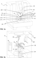
- FIGS. 1a and 1b show in perspective view an embodiment of a machine tool 2 for machining pre-toothed workpieces, wherein Fig. 1b an enlargement of the Fig. 1a framed section E.
- the embodiment shown here is a machine tool for the rolling machining of rotating parts with groove-shaped profiles.
- Such a machine tool is described in the publication WO2021008915A1 described.
- the machine tool 2 has a workpiece carrier 20, a workpiece spindle 21 arranged on the workpiece carrier 20, which defines a workpiece spindle axis A, wherein the workpiece spindle 21 has a workpiece spindle housing 211 and a Workpiece spindle housing 211 has a workpiece spindle shaft 212 rotatable about the workpiece spindle axis A for the rotational drive of a pre-toothed workpiece to be machined, as well as a clamping means 22, wherein the clamping means 22 is designed to hold a workpiece to be machined.
- a Cartesian coordinate system K M with an X M direction, a Y M direction and a Z M direction related to the workpiece carrier 20 is shown in Fig.
- the workpiece carrier 20 in the embodiment shown here is a workpiece carriage movable in the Y M direction.
- the machine tool 2 shown here also has a sensor positioning device 25, which is arranged on a tool carrier 24, wherein a tool spindle 241 for the rotational drive of a machining tool is arranged on the tool carrier 24.
- the sensor positioning device 25 is movable together with the tool carrier 24 in the X M direction and in the Z M direction and has a sensor positioning arm 251, which is linearly displaceable in a Y M /Z M plane and in which the centering sensor 1 is arranged.
- the centering sensor 1 is aligned antiparallel to the Y M direction here.
- Fig. 1a and 1b For illustration purposes, various embodiments of a calibration piece 10 are arranged in the same machine tool 2. In practice, however, it is usually sufficient if the machine tool has only one of these embodiments of the calibration piece 10. As can be seen from the Fig. 1b As can be seen, the various embodiments are arranged in the machine tool in such a way that the centering sensor 1 can be moved along the calibration piece 10 using the sensor positioning device 25 to determine its response behavior, the centering sensor always remaining aligned antiparallel to the Y M direction during the movements 1. In order to achieve a movement of the calibration piece 10 relative to the centering sensor 1 in the Y M direction, the workpiece carrier 20 can also be moved in the machine tool 2 shown here. Also visible is a tactile probe 30 arranged on the tool carrier 24, which can be used to determine the calibration location C M of the calibration piece 10 in the coordinate system K M of the machine tool 2.
- FIG. 2a shown image section D 1 of the Fig. 1b
- Two embodiments of the calibration piece 10 can be seen. Both embodiments are arranged on the workpiece spindle housing 211.
- the first one shown in the image section in a front plane Embodiment has a cuboid-shaped base body, wherein the base body has a first groove 11 with a rectangular cross-section, wherein the first groove 11 runs in the X M direction.
- the second embodiment, shown in the image section in a rear plane protrudes from a beveled surface of the workpiece spindle housing 211 and also has a first groove 11 running in the X M direction with a rectangular cross-section.
- Fig. 2a shown image section D 1 of the Fig. 1b
- these two embodiments are arranged on the workpiece spindle housing in such a way that the groove 11 runs in a tangential direction with respect to the workpiece spindle 21.
- the centering sensor 1 can be moved on a side of the calibration piece 10 having the groove 11 in a tangential direction along the groove 11 and/or in the Z M direction (which corresponds to an axial direction with respect to the workpiece spindle 21) and/or in the Y M direction (which corresponds to a radial direction with respect to the workpiece spindle 21).
- FIG. 2b shown image section D 2 of the Fig. 1b
- a third embodiment of the calibration piece 10 can be seen, which is arranged on the workpiece carrier 20.
- the Fig. 2b The third embodiment shown has a cuboid-shaped base body, wherein the base body has a first groove 11 with a rectangular cross-section.
- the base body of this third embodiment of the calibration piece 10 also has a second groove 12, which runs perpendicular to the first groove 11 and opens into the first groove 11, wherein said second groove 12 has a trapezoidal cross-section.
- the calibration piece 10 On one side of the calibration piece 10, which is opposite the side having the groove 11, the calibration piece 10 has a further groove 11', which runs parallel to the groove 11.
- this third embodiment of the calibration piece 10 is arranged on the workpiece carriage such that the second groove 12 runs parallel to the workpiece spindle axis A, thereby imitating the shape and orientation of a tooth gap in a workpiece to be machined.
- the centering sensor 1 can be moved on a side of the calibration piece 10 having the grooves 11 and 12 in a tangential direction along the groove 11 and/or in the Z M direction (which corresponds to an axial direction with respect to the workpiece spindle 21) and/or in the Y M direction (which corresponds to a radial direction with respect to the workpiece spindle 21).
- this embodiment of the calibration piece can also be mounted on the workpiece carrier (20) rotated by 180°, whereby the groove 12' with the rectangular cross-section is then aligned towards the centering sensor 1 during the calibration process.
- a fourth embodiment of the calibration piece 10 can be seen, which is detachably arranged in the clamping means 22.
- This fourth embodiment of the calibration piece 10 is disc-shaped and has an outer profile with calibration teeth 13, 13'.
- two calibration teeth 13, 13' are located radially opposite one another, the first calibration tooth 13 having a rectangular shape, while the second calibration tooth 13 has a trapezoidal shape.
- the calibration teeth 13, 13' are aligned in the Y M direction.
- the centering sensor 1 To determine the response behavior of the centering sensor 1, it can be moved in a tangential direction with respect to the workpiece spindle (X M direction), whereby the centering sensor 1, which is aligned antiparallel to the Y M direction, can scan one of the two calibration teeth (here the one with the rectangular shape, 13) without contact. If scanning of the calibration tooth 13' (trapezoidal shape) is preferred, the calibration piece can be arranged rotated by 180°.
- image section D 4 of the Fig. 1b 1 shows a fifth embodiment of the calibration piece 10, which is arranged on the clamping means 22.
- the fifth embodiment of the calibration piece 10 has a cuboid projection 14 which extends radially from a surface of the clamping means 21, wherein the cuboid projection 14 is flanked by two orientation surfaces 15 protruding into the surface of the clamping means.
- the projection points in the Y M direction and the flanking orientation surfaces 15 are arranged on both sides of the projection 14 with respect to the tangential direction such that the orientation surfaces 15 lie in the X M /Z M plane.
- Fig. 2e shows a perspective view of a machine tool 2 with a sixth embodiment of the calibration piece, which is arranged on the workpiece spindle housing 211.
- this sixth embodiment of the calibration piece has a cylindrical base body which is arranged on a cuboid-shaped support 17.
- the cylindrical base body has a cylinder axis 16, which here runs parallel to the Y M axis.
- Fig. 2g shows a side view of a machine tool 2 with a seventh embodiment of the calibration piece, which is arranged on the workpiece spindle housing 211.
- this seventh embodiment of the calibration piece has a dome-shaped base body which is arranged on a cuboid-shaped support 17, wherein the dome-shaped base body in Y M direction.
- Fig. 3a and 3b show a preferred arrangement of the calibration piece 10, which corresponds to the first embodiment in Fig. 2a corresponds to, in the machine tool 2, where Fig. 3b an enlargement of the Fig. 3a framed section F.
- the sensor positioning arm 251 has a sensor holder 26, which forms a mechanical receptacle for a sensor carrier 27.
- the sensor carrier 27 has a stop element 271, which serves as a positioning aid for mounting the sensor carrier 27 in the sensor holder 26.
- the centering sensor 1 has a centering sensor surface O and is mounted in the sensor carrier 27 such that the centering sensor surface O is at a defined distance e from the stop element 271.
- Such a sensor carrier 27 forms a uniform interface to the sensor holder 26 for centering sensors 1 of different sizes. If the centering sensor 1 needs to be replaced, it can be removed from the sensor holder 26 together with the sensor carrier 27. A new centering sensor is then installed in the sensor carrier 27 such that its centering sensor surface is also at the same defined distance e from the stop element 271, which can be checked using a suitable measuring device before the sensor carrier 27 is reinstalled in the sensor holder 26.
- the sensor positioning device 25 with the centering sensor 1 in the sensor carrier 26 can be moved collision-free to the calibration piece 10 despite a machining tool 28 arranged on the tool carrier 24 in order to scan the calibration piece 10 contactlessly along the directions X M , Y M and Z M , wherein the centering sensor 1 is aligned antiparallel to the Y M direction.
- FIG. 4a-4d A method for calibrating a contactless centering sensor 1 according to the present invention that outputs switching signals is illustrated in a schematic (not to scale) manner.
- the centering sensor shown in this exemplary embodiment has a switching range B that extends from a centering sensor surface O to a switching boundary surface G, shown here in dashed lines, and defines a fictitious sensor axis AS . If material penetrates the switching range B, the switching signal output by the centering sensor 1 changes.
- the workpiece measuring position PW should be calculated such that the most symmetrical response behavior of the centering sensor 1 is achieved.
- Such a symmetrical response behavior is achieved when the fictitious sensor axis AS is aligned with a predefined measuring axis AM (here parallel to the YM direction in a predefined height in Z M direction), and when the centering sensor surface O is spaced by a predefined measuring distance d from the tip circle K, such that the tip circle K crosses the switching area B (see Fig. 4a ).
- the fictitious sensor axis A S of the centering sensor 1 is determined using the calibration piece 10, wherein the calibration piece 10 has a known geometry and is located at a known calibration location C M in the coordinate system K M of the workpiece carrier. For this purpose, the centering sensor 1 is brought close to the calibration piece.
- the first step ( Fig. 4b ) a peak switching point S of the switching range is determined by approaching an end face F of the calibration piece 10, the end face here being located in the X M -Z M plane. If a theoretical position of the centering sensor 1 in the coordinate system KM of the workpiece carrier is already known, for example because it has been determined by a geometric measurement in the machine and stored in the sensor control, then the determination of the peak switching point S can also be omitted, since the known theoretical position of the centering sensor 1 allows the latter to be moved directly to a predefined calibration position PC .
- the centering sensor can also be in a current position which deviates from the theoretical position; for example, if the machine is at a different temperature than during the determination of the theoretical position.
- the current position of the centering sensor can deviate from the theoretical position if there is an installation error; for example, if the centering sensor surface O does not meet the Fig. 3c shown, provided distance e from the stop element, or if the stop element 271 of the sensor carrier 27 has not been mounted flush with the sensor holder 26.
- a second step ( Fig. 4c and Fig. 4d ) the centering sensor 1 is moved antiparallel to the Y M direction closer to the calibration piece 10, ideally in such a way that the centering sensor surface O is spaced from the end face F by the predefined measuring distance d, which should then also occur between the centering sensor surface O and a tip circle K of the workpiece 23, when the centering sensor 1 (as in Fig. 4a shown) is in the workpiece measuring position P W.
- edge switching points are determined which are located on the switching boundary surface G of the switching range B of the centering sensor in the X M and Z M directions.
- this third step is carried out at a single measuring distance d in the Y M direction, whereby two edge switching points are preferably determined in the X M direction and in the Z M direction.
- Fig. 4c As an example, it can be seen how the centering sensor is moved past a first edge k 1 of the calibration piece parallel to the X M direction to determine a first edge switching point S F1 , while Fig.
- FIG. 4d shows how the centering sensor is moved anti-parallel to the X M direction past a second edge k 2 of the calibration piece to determine a second edge switching point S F2 .
- the determined edge switching points are stored in a memory 31 of the sensor controller 3.
- a theoretical central point S Z of the switching range B can then be determined from the stored edge switching points.
- a fictitious axis AS is placed through this theoretical central point S Z , this fictitious axis AS being normal to the X M / Z M plane.
- the centering sensor is then brought into the workpiece measuring position P w in such a way that this fictitious sensor axis A S lies on the desired measuring axis A M , as in Fig. 4a shown ideally in such a way that the central point S Z lies on an intersection point of the measuring axis A M with the tip circle K, whereby the most symmetrical response behavior of the centering sensor 1 is achieved.
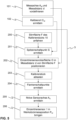
- Fig. 5 shows the above-described example of a calibration method of a centering sensor 1 in a machine tool 2 for machining pre-toothed workpieces, for the implementation of which method the machine tool is designed according to an embodiment of the present invention.
- a measuring axis AM and a measuring distance d are defined 101, and the calibration location CM is determined 102, at which the calibration piece 10 is arranged.
- the centering sensor 1 is moved 200 towards an end face F of the calibration piece and in the process a peak switching point S of the switching range B is determined 201.
- the centering sensor 1 is positioned such that the centering sensor surface O is spaced by the measuring distance d from the end face of the calibration piece 10 is spaced 202. Now the centering sensor 1 is moved along the calibration piece 10 in order to scan it without contact 203. Meanwhile, the centering sensor 1 outputs switching signals from which edge switching points are determined 204. From these edge switching points, a fictitious sensor axis A S is then determined 205. In a last step 206, the centering sensor 1 is brought into a workpiece measuring position P W calculated by the sensor control 3, in which the determined fictitious sensor axis A S coincides with the measuring axis A M.
Landscapes
- Engineering & Computer Science (AREA)
- Mechanical Engineering (AREA)
- Human Computer Interaction (AREA)
- Manufacturing & Machinery (AREA)
- Physics & Mathematics (AREA)
- General Physics & Mathematics (AREA)
- Automation & Control Theory (AREA)
- Automatic Control Of Machine Tools (AREA)
- Gear Processing (AREA)
- Machine Tool Sensing Apparatuses (AREA)
- Numerical Control (AREA)
- Drilling And Boring (AREA)
Applications Claiming Priority (2)
| Application Number | Priority Date | Filing Date | Title |
|---|---|---|---|
| CH70259/21A CH718956A1 (de) | 2021-09-10 | 2021-09-10 | Werkzeugmaschine mit Kalibriervorrichtung zur Kalibrierung eines Einzentriersensors. |
| PCT/EP2022/073814 WO2023036630A1 (de) | 2021-09-10 | 2022-08-26 | Werkzeugmaschine mit kalibriervorrichtung zur kalibrierung eines einzentriersensors |
Publications (3)
| Publication Number | Publication Date |
|---|---|
| EP4399046A1 EP4399046A1 (de) | 2024-07-17 |
| EP4399046B1 true EP4399046B1 (de) | 2025-05-14 |
| EP4399046C0 EP4399046C0 (de) | 2025-05-14 |
Family
ID=83355214
Family Applications (1)
| Application Number | Title | Priority Date | Filing Date |
|---|---|---|---|
| EP22772434.1A Active EP4399046B1 (de) | 2021-09-10 | 2022-08-26 | Werkzeugmaschine mit kalibriervorrichtung zur kalibrierung eines einzentriersensors |
Country Status (8)
| Country | Link |
|---|---|
| US (1) | US20240375198A1 (https=) |
| EP (1) | EP4399046B1 (https=) |
| JP (1) | JP2024533073A (https=) |
| CN (1) | CN118076452A (https=) |
| CH (1) | CH718956A1 (https=) |
| MX (1) | MX2024002975A (https=) |
| TW (1) | TW202410994A (https=) |
| WO (1) | WO2023036630A1 (https=) |
Families Citing this family (1)
| Publication number | Priority date | Publication date | Assignee | Title |
|---|---|---|---|---|
| CN118875827B (zh) * | 2024-10-08 | 2025-02-14 | 苏州新实达精密电子科技有限公司 | 模具运动检测校准装置及监测校准方法 |
Family Cites Families (13)
| Publication number | Priority date | Publication date | Assignee | Title |
|---|---|---|---|---|
| GB2108715B (en) * | 1981-09-15 | 1985-05-01 | Renishaw Electrical Ltd | Method of operating a machine tool |
| DE3615365C1 (de) | 1986-05-06 | 1987-08-13 | Liebherr Verzahntech Gmbh | Verfahren zur Bearbeitung der Zahnflanken eines Zahnrades |
| US5297055A (en) * | 1990-04-20 | 1994-03-22 | The Gleason Works | Multi-functional measurement system |
| JP2718850B2 (ja) * | 1992-02-10 | 1998-02-25 | 本田技研工業株式会社 | 歯車研削機における自動噛合装置 |
| JP5491098B2 (ja) * | 2009-08-11 | 2014-05-14 | オークマ株式会社 | 工作機械のタッチプローブのキャリブレーション方法及び工作機械 |
| JP5255012B2 (ja) * | 2010-04-02 | 2013-08-07 | 三菱重工業株式会社 | 歯車測定装置の校正方法 |
| US8577495B2 (en) * | 2010-11-22 | 2013-11-05 | GM Global Technology Operations LLC | Automatic calibration and compensation for a CNC machine table and an associated probe |
| DE102013003585A1 (de) * | 2013-03-01 | 2014-09-04 | Liebherr-Verzahntechnik Gmbh | Verfahren zur Verzahnungsmessung sowie Messeinrichtung und Verzahnmaschine |
| EP3192611A1 (en) * | 2016-01-12 | 2017-07-19 | Renishaw plc | Calibration device and method |
| DE102017000072A1 (de) * | 2017-01-05 | 2018-07-05 | Liebherr-Verzahntechnik Gmbh | Verfahren zum automatischen Bestimmen der geometrischen Abmessungen eines Werkzeuges in einer Verzahnmaschine |
| DE102017120788A1 (de) * | 2017-09-08 | 2019-03-14 | Liebherr-Verzahntechnik Gmbh | Verfahren und Vorrichtung zum Wälzschälen |
| DE102019104812A1 (de) | 2019-02-26 | 2020-08-27 | KAPP NILES GmbH & Co. KG | Verfahren zum Schleifen oder Polieren eines Zahnrads oder eines Werkstücks mit einem zahnradähnlichen Profil in einer Schleif- oder Poliermaschine |
| CH715794B8 (de) * | 2019-07-17 | 2020-11-13 | Reishauer Ag | Werkzeugmaschine für die Wälzbearbeitung von Rotationsteilen mit nutförmigen Profilen. |
-
2021
- 2021-09-10 CH CH70259/21A patent/CH718956A1/de unknown
-
2022
- 2022-08-18 TW TW111131161A patent/TW202410994A/zh unknown
- 2022-08-26 MX MX2024002975A patent/MX2024002975A/es unknown
- 2022-08-26 JP JP2024513076A patent/JP2024533073A/ja active Pending
- 2022-08-26 EP EP22772434.1A patent/EP4399046B1/de active Active
- 2022-08-26 WO PCT/EP2022/073814 patent/WO2023036630A1/de not_active Ceased
- 2022-08-26 CN CN202280061155.9A patent/CN118076452A/zh active Pending
- 2022-08-26 US US18/690,509 patent/US20240375198A1/en active Pending
Also Published As
| Publication number | Publication date |
|---|---|
| CN118076452A (zh) | 2024-05-24 |
| CH718956A1 (de) | 2023-03-15 |
| WO2023036630A1 (de) | 2023-03-16 |
| MX2024002975A (es) | 2024-03-27 |
| EP4399046A1 (de) | 2024-07-17 |
| JP2024533073A (ja) | 2024-09-12 |
| TW202410994A (zh) | 2024-03-16 |
| EP4399046C0 (de) | 2025-05-14 |
| US20240375198A1 (en) | 2024-11-14 |
Similar Documents
| Publication | Publication Date | Title |
|---|---|---|
| EP3456453B1 (de) | Verfahren und vorrichtung zum wälzschälen | |
| DE69624577T2 (de) | Verfahren und vorrichtung zum ausrichten von messerköpfen | |
| EP1696289B1 (de) | Verfahren zum Vermessen einer programmgesteuerten Werkzeugmaschine | |
| DE1932010C3 (de) | Vorrichtung zum Prüfen von Werkstücken | |
| EP2916996B1 (de) | Werkzeugmaschine und verfahren zur vermessung eines werkstücks | |
| EP0779849B1 (de) | Verfahren und vorrichtung zur erfassung und kompensation von füge- und verschleissfehlern beim feinbohren | |
| DE19928500B4 (de) | Verfahren und Vorrichtung zur automatischen Messung von Prozess- und Werkstückkennwerten beim Schleifen von Zahnrädern | |
| DE69120271T2 (de) | Verfahren und Vorrichtung zum Einrichten von Werkstücken auf Maschinen zur Zahnradherstellung. | |
| EP4093571B1 (de) | Verfahren zum bearbeiten eines werkstücks mit zwei verzahnungen, positioniervorrichtung zum ermitteln einer referenzdrehwinkellage des werkstücks und werkzeugmaschine mit einer derartigen positioniervorrichtung | |
| EP4027936B1 (de) | Haltevorrichtung für ein dentales werkstück | |
| DE69712749T2 (de) | Verfahren zur berechnung eines werkstücks zur bearbeitung | |
| DE2406170A1 (de) | Mess- und ueberwachungsverfahren zur ueberpruefung der betriebszustaende in spitzenlosen rundschleifmaschinen und vorrichtung zur durchfuehrung des verfahrens | |
| EP4399046B1 (de) | Werkzeugmaschine mit kalibriervorrichtung zur kalibrierung eines einzentriersensors | |
| DE2705200A1 (de) | Verfahren und einrichtung zum ausgerichteten spannen eines werkstueckes | |
| DE3212078C2 (de) | Selbsttätig arbeitendes Prüfgerät für die Kreisteilungsprüfung von Zahnrädern sowie Verfahren zum Messen der Verzahnungsrundlaufabweichungen, Zahndickenabweichungen und Zahnlückenabweichungen von Zahnrädern | |
| EP1366394A2 (de) | Verfahren und vorrichtung zum vermessen und bearbeiten von werkstücken | |
| DE3320983A1 (de) | Transportables geraet zur pruefung des zahnflankenprofils und der zahnflankenlinien (zahnschraege) von zahnraedern auf verzahnmaschinen oder zahnflankenschleifmaschinen sowie zur positionierung dieses geraetes und zum orientieren des messtasters an der verzahnung fuer den messvorgang | |
| DE102013003585A1 (de) | Verfahren zur Verzahnungsmessung sowie Messeinrichtung und Verzahnmaschine | |
| DE2931273C2 (de) | Vorrichtung zur Prüfung eines Gewindes | |
| DE102018101407B4 (de) | Werkzeugmaschine und Verfahren zur Vorbereitung einer Bearbeitung eines spanabtragenden Rotationswerkzeugs | |
| DE2707278A1 (de) | Verfahren zum ueberpruefen der abmessungen eines in einer werkzeugmaschine bearbeiteten werkstueckes | |
| DE4221688A1 (de) | Verfahren und maschine zur werkstoffteilung bei formschleifmaschinen | |
| DE10205212A1 (de) | Meßeinrichtung für Maschinen zum Bearbeiten von Werkstücken, insbesondere von Kurbelwellen, Nockenwellen | |
| DE102005022482A1 (de) | Antaststift und damit ausgestattetes Tastsystem | |
| DE3500050C2 (de) | Meßkopf für Rundschleifmaschinen |
Legal Events
| Date | Code | Title | Description |
|---|---|---|---|
| STAA | Information on the status of an ep patent application or granted ep patent |
Free format text: STATUS: UNKNOWN |
|
| STAA | Information on the status of an ep patent application or granted ep patent |
Free format text: STATUS: THE INTERNATIONAL PUBLICATION HAS BEEN MADE |
|
| PUAI | Public reference made under article 153(3) epc to a published international application that has entered the european phase |
Free format text: ORIGINAL CODE: 0009012 |
|
| STAA | Information on the status of an ep patent application or granted ep patent |
Free format text: STATUS: REQUEST FOR EXAMINATION WAS MADE |
|
| 17P | Request for examination filed |
Effective date: 20240311 |
|
| AK | Designated contracting states |
Kind code of ref document: A1 Designated state(s): AL AT BE BG CH CY CZ DE DK EE ES FI FR GB GR HR HU IE IS IT LI LT LU LV MC MK MT NL NO PL PT RO RS SE SI SK SM TR |
|
| DAV | Request for validation of the european patent (deleted) | ||
| DAX | Request for extension of the european patent (deleted) | ||
| GRAP | Despatch of communication of intention to grant a patent |
Free format text: ORIGINAL CODE: EPIDOSNIGR1 |
|
| STAA | Information on the status of an ep patent application or granted ep patent |
Free format text: STATUS: GRANT OF PATENT IS INTENDED |
|
| INTG | Intention to grant announced |
Effective date: 20250110 |
|
| GRAS | Grant fee paid |
Free format text: ORIGINAL CODE: EPIDOSNIGR3 |
|
| GRAA | (expected) grant |
Free format text: ORIGINAL CODE: 0009210 |
|
| STAA | Information on the status of an ep patent application or granted ep patent |
Free format text: STATUS: THE PATENT HAS BEEN GRANTED |
|
| AK | Designated contracting states |
Kind code of ref document: B1 Designated state(s): AL AT BE BG CH CY CZ DE DK EE ES FI FR GB GR HR HU IE IS IT LI LT LU LV MC MK MT NL NO PL PT RO RS SE SI SK SM TR |
|
| REG | Reference to a national code |
Ref country code: GB Ref legal event code: FG4D Free format text: NOT ENGLISH |
|
| REG | Reference to a national code |
Ref country code: CH Ref legal event code: EP |
|
| REG | Reference to a national code |
Ref country code: IE Ref legal event code: FG4D Free format text: LANGUAGE OF EP DOCUMENT: GERMAN |
|
| U01 | Request for unitary effect filed |
Effective date: 20250514 |
|
| U07 | Unitary effect registered |
Designated state(s): AT BE BG DE DK EE FI FR IT LT LU LV MT NL PT RO SE SI Effective date: 20250520 |
|
| U20 | Renewal fee for the european patent with unitary effect paid |
Year of fee payment: 4 Effective date: 20250811 |
|
| PG25 | Lapsed in a contracting state [announced via postgrant information from national office to epo] |
Ref country code: ES Free format text: LAPSE BECAUSE OF FAILURE TO SUBMIT A TRANSLATION OF THE DESCRIPTION OR TO PAY THE FEE WITHIN THE PRESCRIBED TIME-LIMIT Effective date: 20250514 |
|
| PG25 | Lapsed in a contracting state [announced via postgrant information from national office to epo] |
Ref country code: NO Free format text: LAPSE BECAUSE OF FAILURE TO SUBMIT A TRANSLATION OF THE DESCRIPTION OR TO PAY THE FEE WITHIN THE PRESCRIBED TIME-LIMIT Effective date: 20250814 Ref country code: GR Free format text: LAPSE BECAUSE OF FAILURE TO SUBMIT A TRANSLATION OF THE DESCRIPTION OR TO PAY THE FEE WITHIN THE PRESCRIBED TIME-LIMIT Effective date: 20250815 |
|
| PG25 | Lapsed in a contracting state [announced via postgrant information from national office to epo] |
Ref country code: PL Free format text: LAPSE BECAUSE OF FAILURE TO SUBMIT A TRANSLATION OF THE DESCRIPTION OR TO PAY THE FEE WITHIN THE PRESCRIBED TIME-LIMIT Effective date: 20250514 |
|
| PG25 | Lapsed in a contracting state [announced via postgrant information from national office to epo] |
Ref country code: HR Free format text: LAPSE BECAUSE OF FAILURE TO SUBMIT A TRANSLATION OF THE DESCRIPTION OR TO PAY THE FEE WITHIN THE PRESCRIBED TIME-LIMIT Effective date: 20250514 |
|
| PGFP | Annual fee paid to national office [announced via postgrant information from national office to epo] |
Ref country code: CH Payment date: 20250901 Year of fee payment: 4 |
|
| PG25 | Lapsed in a contracting state [announced via postgrant information from national office to epo] |
Ref country code: RS Free format text: LAPSE BECAUSE OF FAILURE TO SUBMIT A TRANSLATION OF THE DESCRIPTION OR TO PAY THE FEE WITHIN THE PRESCRIBED TIME-LIMIT Effective date: 20250814 |
|
| PG25 | Lapsed in a contracting state [announced via postgrant information from national office to epo] |
Ref country code: IS Free format text: LAPSE BECAUSE OF FAILURE TO SUBMIT A TRANSLATION OF THE DESCRIPTION OR TO PAY THE FEE WITHIN THE PRESCRIBED TIME-LIMIT Effective date: 20250914 |
|
| PG25 | Lapsed in a contracting state [announced via postgrant information from national office to epo] |
Ref country code: SM Free format text: LAPSE BECAUSE OF FAILURE TO SUBMIT A TRANSLATION OF THE DESCRIPTION OR TO PAY THE FEE WITHIN THE PRESCRIBED TIME-LIMIT Effective date: 20250514 |
|
| PG25 | Lapsed in a contracting state [announced via postgrant information from national office to epo] |
Ref country code: CZ Free format text: LAPSE BECAUSE OF FAILURE TO SUBMIT A TRANSLATION OF THE DESCRIPTION OR TO PAY THE FEE WITHIN THE PRESCRIBED TIME-LIMIT Effective date: 20250514 |
|
| PG25 | Lapsed in a contracting state [announced via postgrant information from national office to epo] |
Ref country code: SK Free format text: LAPSE BECAUSE OF FAILURE TO SUBMIT A TRANSLATION OF THE DESCRIPTION OR TO PAY THE FEE WITHIN THE PRESCRIBED TIME-LIMIT Effective date: 20250514 |
|
| PLBE | No opposition filed within time limit |
Free format text: ORIGINAL CODE: 0009261 |
|
| STAA | Information on the status of an ep patent application or granted ep patent |
Free format text: STATUS: NO OPPOSITION FILED WITHIN TIME LIMIT |
|
| REG | Reference to a national code |
Ref country code: CH Ref legal event code: L10 Free format text: ST27 STATUS EVENT CODE: U-0-0-L10-L00 (AS PROVIDED BY THE NATIONAL OFFICE) Effective date: 20260325 |
|
| PG25 | Lapsed in a contracting state [announced via postgrant information from national office to epo] |
Ref country code: MC Free format text: LAPSE BECAUSE OF FAILURE TO SUBMIT A TRANSLATION OF THE DESCRIPTION OR TO PAY THE FEE WITHIN THE PRESCRIBED TIME-LIMIT Effective date: 20250514 |
|
| 26N | No opposition filed |
Effective date: 20260217 |