EP4398690A2 - Wärmeableitungssystem und festkörpertransformatorleistungsvorrichtung - Google Patents
Wärmeableitungssystem und festkörpertransformatorleistungsvorrichtung Download PDFInfo
- Publication number
- EP4398690A2 EP4398690A2 EP23208514.2A EP23208514A EP4398690A2 EP 4398690 A2 EP4398690 A2 EP 4398690A2 EP 23208514 A EP23208514 A EP 23208514A EP 4398690 A2 EP4398690 A2 EP 4398690A2
- Authority
- EP
- European Patent Office
- Prior art keywords
- temperature
- module
- power
- throttle valve
- airflow
- Prior art date
- Legal status (The legal status is an assumption and is not a legal conclusion. Google has not performed a legal analysis and makes no representation as to the accuracy of the status listed.)
- Pending
Links
- 230000017525 heat dissipation Effects 0.000 title claims abstract description 46
- 238000006243 chemical reaction Methods 0.000 claims abstract description 94
- 239000002826 coolant Substances 0.000 claims abstract description 76
- 238000001816 cooling Methods 0.000 claims description 45
- XLYOFNOQVPJJNP-UHFFFAOYSA-N water Substances O XLYOFNOQVPJJNP-UHFFFAOYSA-N 0.000 claims description 24
- 238000002955 isolation Methods 0.000 claims description 7
- 230000007423 decrease Effects 0.000 claims description 3
- 229910001335 Galvanized steel Inorganic materials 0.000 claims description 2
- 239000008397 galvanized steel Substances 0.000 claims description 2
- 238000010586 diagram Methods 0.000 description 12
- 239000011159 matrix material Substances 0.000 description 10
- 238000004146 energy storage Methods 0.000 description 8
- YQNRVGJCPCNMKT-LFVJCYFKSA-N 2-[(e)-[[2-(4-benzylpiperazin-1-ium-1-yl)acetyl]hydrazinylidene]methyl]-6-prop-2-enylphenolate Chemical compound [O-]C1=C(CC=C)C=CC=C1\C=N\NC(=O)C[NH+]1CCN(CC=2C=CC=CC=2)CC1 YQNRVGJCPCNMKT-LFVJCYFKSA-N 0.000 description 6
- 101100462537 Caenorhabditis elegans pac-1 gene Proteins 0.000 description 6
- 101100117764 Mus musculus Dusp2 gene Proteins 0.000 description 6
- 238000010438 heat treatment Methods 0.000 description 5
- 101100028920 Neurospora crassa (strain ATCC 24698 / 74-OR23-1A / CBS 708.71 / DSM 1257 / FGSC 987) cfp gene Proteins 0.000 description 4
- 238000009833 condensation Methods 0.000 description 4
- 230000005494 condensation Effects 0.000 description 4
- 230000000694 effects Effects 0.000 description 4
- 230000007246 mechanism Effects 0.000 description 3
- RYGMFSIKBFXOCR-UHFFFAOYSA-N Copper Chemical compound [Cu] RYGMFSIKBFXOCR-UHFFFAOYSA-N 0.000 description 2
- 238000010521 absorption reaction Methods 0.000 description 2
- 229910052802 copper Inorganic materials 0.000 description 2
- 239000010949 copper Substances 0.000 description 2
- 239000003507 refrigerant Substances 0.000 description 2
- 238000009825 accumulation Methods 0.000 description 1
- 230000002457 bidirectional effect Effects 0.000 description 1
- 230000033228 biological regulation Effects 0.000 description 1
- 238000010276 construction Methods 0.000 description 1
- 239000012809 cooling fluid Substances 0.000 description 1
- 230000008878 coupling Effects 0.000 description 1
- 238000010168 coupling process Methods 0.000 description 1
- 238000005859 coupling reaction Methods 0.000 description 1
- 230000003247 decreasing effect Effects 0.000 description 1
- 238000005516 engineering process Methods 0.000 description 1
- 239000012530 fluid Substances 0.000 description 1
- 238000009413 insulation Methods 0.000 description 1
- 239000007788 liquid Substances 0.000 description 1
- 239000004065 semiconductor Substances 0.000 description 1
- 230000035939 shock Effects 0.000 description 1
Images






Classifications
-
- H—ELECTRICITY
- H05—ELECTRIC TECHNIQUES NOT OTHERWISE PROVIDED FOR
- H05K—PRINTED CIRCUITS; CASINGS OR CONSTRUCTIONAL DETAILS OF ELECTRIC APPARATUS; MANUFACTURE OF ASSEMBLAGES OF ELECTRICAL COMPONENTS
- H05K7/00—Constructional details common to different types of electric apparatus
- H05K7/20—Modifications to facilitate cooling, ventilating, or heating
- H05K7/2089—Modifications to facilitate cooling, ventilating, or heating for power electronics, e.g. for inverters for controlling motor
- H05K7/20927—Liquid coolant without phase change
-
- H—ELECTRICITY
- H05—ELECTRIC TECHNIQUES NOT OTHERWISE PROVIDED FOR
- H05K—PRINTED CIRCUITS; CASINGS OR CONSTRUCTIONAL DETAILS OF ELECTRIC APPARATUS; MANUFACTURE OF ASSEMBLAGES OF ELECTRICAL COMPONENTS
- H05K7/00—Constructional details common to different types of electric apparatus
- H05K7/20—Modifications to facilitate cooling, ventilating, or heating
- H05K7/20218—Modifications to facilitate cooling, ventilating, or heating using a liquid coolant without phase change in electronic enclosures
- H05K7/20272—Accessories for moving fluid, for expanding fluid, for connecting fluid conduits, for distributing fluid, for removing gas or for preventing leakage, e.g. pumps, tanks or manifolds
-
- H—ELECTRICITY
- H05—ELECTRIC TECHNIQUES NOT OTHERWISE PROVIDED FOR
- H05K—PRINTED CIRCUITS; CASINGS OR CONSTRUCTIONAL DETAILS OF ELECTRIC APPARATUS; MANUFACTURE OF ASSEMBLAGES OF ELECTRICAL COMPONENTS
- H05K7/00—Constructional details common to different types of electric apparatus
- H05K7/20—Modifications to facilitate cooling, ventilating, or heating
- H05K7/2089—Modifications to facilitate cooling, ventilating, or heating for power electronics, e.g. for inverters for controlling motor
- H05K7/20909—Forced ventilation, e.g. on heat dissipaters coupled to components
-
- H—ELECTRICITY
- H05—ELECTRIC TECHNIQUES NOT OTHERWISE PROVIDED FOR
- H05K—PRINTED CIRCUITS; CASINGS OR CONSTRUCTIONAL DETAILS OF ELECTRIC APPARATUS; MANUFACTURE OF ASSEMBLAGES OF ELECTRICAL COMPONENTS
- H05K7/00—Constructional details common to different types of electric apparatus
- H05K7/20—Modifications to facilitate cooling, ventilating, or heating
- H05K7/2089—Modifications to facilitate cooling, ventilating, or heating for power electronics, e.g. for inverters for controlling motor
- H05K7/20909—Forced ventilation, e.g. on heat dissipaters coupled to components
- H05K7/20918—Forced ventilation, e.g. on heat dissipaters coupled to components the components being isolated from air flow, e.g. hollow heat sinks, wind tunnels or funnels
-
- H—ELECTRICITY
- H05—ELECTRIC TECHNIQUES NOT OTHERWISE PROVIDED FOR
- H05K—PRINTED CIRCUITS; CASINGS OR CONSTRUCTIONAL DETAILS OF ELECTRIC APPARATUS; MANUFACTURE OF ASSEMBLAGES OF ELECTRICAL COMPONENTS
- H05K7/00—Constructional details common to different types of electric apparatus
- H05K7/20—Modifications to facilitate cooling, ventilating, or heating
- H05K7/2089—Modifications to facilitate cooling, ventilating, or heating for power electronics, e.g. for inverters for controlling motor
- H05K7/20945—Thermal management, e.g. inverter temperature control
Definitions
- the present disclosure provides a solid-state transformer power apparatus.
- the solid-state transformer power apparatus includes a housing, a plurality of AC-to-DC conversion modules, and a heat dissipation system.
- the housing includes a housing block.
- the plurality of AC-to-DC conversion modules are disposed in the housing block, and each AC-to-DC conversion module includes a power module.
- the heat dissipation system dissipates heat for the power module, and the heat dissipation system includes a water cooling component and an air cooling component.
- the water cooling component provides a coolant to the power module to absorb a heat source generated by the power module.
- the air cooling component exchanges heat between the coolant and an airflow flowing through the power module.
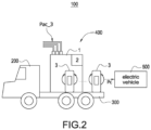
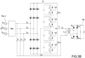
- FIG. 3A shows a block circuit diagram of an electric vehicle charging apparatus according to a first embodiment of the present disclosure, and also refer to FIG. 2 .
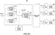
- the SST power module 1 receives the MV-AC, i.e., a three-phase input power source Pac_3, usually between 1 kV and 35 kV, and converts the input power source Pac_3 into a plurality of DC power sources Pdc.
- the deployment module 2 is coupled between the SST power module 1 and the plurality of charging piles 3, and the deployment module 2 provides a plurality of output power sources Po to the plurality of charging piles 3 based on the plurality of DC power sources Pdc.
- the plurality of charging piles 3 respectively receive the plurality of output power sources Po by coupling to the deployment module 2, and provide a plurality of charging power sources Pc based on the output power sources Po So that the plurality of charging piles 3 can provide the plurality of charging power sources Pc corresponding to the number of the electric vehicles 500 connected to the charging piles to charge the plurality of electric vehicles 500. Therefore, the plurality of charging piles 3 can provide appropriate voltage and current (i.e., appropriate power) to charge the plurality of electric vehicles 500 according to the requirements of the plurality of electric vehicles 500.
- the mobile charging station arrives at the location, it only needs to connect the MV-AC (i.e., the three-phase input power source Pac_3) to charge the electric vehicle 500 that needs to be charged anytime and anywhere.
- the deployment module 2 may be a matrix switch assembly, and the matrix switch assembly includes a first switch assembly 20 and a second switch assembly 22.
- the first switch assembly 20 includes a plurality of first switches Q1, and each first switch Q1 is coupled between a negative output end 10- of one of the plurality of AC-to-DC conversion modules 10 (for example, the AC-to-DC conversion module 10A) and a positive output end 10+ of another of the plurality of AC-to-DC conversion modules 10 (for example, the AC-to-DC conversion module 10B) so as to form the series-connected AC-to-DC conversion modules 10.
- the first switch assembly 20 can connect the output ends of the plurality of AC-to-DC conversion modules 10 in series based on the voltage requirements of the plurality of electric vehicles 500, and the number of first switches Q1 is the number of the AC-to-DC conversion modules 10 minus one.
- the second switch assembly 22 includes a plurality of switch rows 222, and each switch row 222 includes a plurality of second switches Q2 and a plurality of third switches Q3.
- the plurality of second switches Q2 make the plurality of positive output ends 10+ of the plurality of AC-to-DC conversion modules 10 be connected in parallel
- the plurality of third switches Q3 make the plurality of negative output ends 10- of the plurality of AC-to-DC conversion modules 10 be connected in parallel so that each switch row 222 forms a parallel-connected node Pn.
- each AC-to-DC conversion module 10 is 200V to 500V Therefore, by operating the first switch assembly 20, two AC-to-DC conversion modules 10 are connected in series to achieve the output voltage of 400V to 1000V, and so on.
- the output voltage of one AC-to-DC conversion module 10, i.e., 500V is provided to the charging pile 3 for the electric vehicle 500.
- the plurality of DC-to-DC conversion modules 12 are coupled to the DC bus DC_BUS and convert the power source on the DC bus DC_BUS into a plurality of first DC power sources Pdc1, and the plurality of first DC power sources Pdc1 are provided to the deployment module 2 according to the circuit structure shown in FIG. 3A . Therefore, the plurality of first DC power sources Pdc1 are associated with the plurality of DC power sources Pdc so that the deployment module 2 can provide a plurality of output power sources Po based on the plurality of DC power sources Pdc.
- the number of the DC-to-DC conversion modules 12 may be different from the number of the AC-to-DC conversion modules 10.
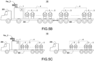
- the SST power apparatus 1B includes a housing 1C, a plurality of AC-to-DC conversion modules 10 (shown in six modules), and a heat dissipation system 14.
- the interior of the housing 1C includes a housing block 1D, and the plurality of AC-to-DC conversion modules 10 are disposed in the housing block 1D.
- the heat dissipation system 14 is disposed in the housing 1C and outside the housing block 1D.
- the heat dissipation system 14 is mainly used to execute the heat dissipation for power modules, such as the half-bridge modules 102, which are the main heating elements, of the AC-to-DC conversion module 10 shown in FIG. 3B .
- FIG. 7 shows a block circuit diagram of the heat dissipation system and power modules according to the present disclosure, and also refer to FIG. 2 to FIG. 5C .
- the heat dissipation system 14 includes a chiller 162, a heat exchanger 182, a first circulation pipeline 164, a second circulation pipeline 166, a first throttle valve 168, and a control module 5.
- the chiller 162, the first circulation pipeline 164, the second circulation pipeline 166, and the first throttle valve 168 belong to the water cooling component 142, and the heat exchanger 182 belongs to the air cooling component 144.
- the first circulation loop L1 is an outer circulation loop
- the second circulation loop L2 is a semi-closed inner circulation loop as shown in FIG. 7 .
- the low-temperature coolant Lc is outputted from the chiller 162 (for example, but not limited to 18 degrees Celsius), and flows back to the chiller 162 (for example, but not limited to 19 degrees Celsius) through the heat exchanger 182 and the outer circulation loop.
- the semi-closed inner circulation loop mainly flows the high-temperature coolant Lh (such as but not limited to 35 degrees Celsius) through the surrounding environment of the power modules 102A so as to absorb and carry out the heat of the surrounding environment of the power modules 102A.
- the semi-closed inner circulation loop is formed into a closed loop by closing the first throttle valve 168, and therefore the high-temperature coolant Lh continuously absorbs the heat of the surrounding environment of the power modules 102A in the closed loop.
- the coolant is, for example but not limited to, liquid conduction medium such as refrigerant, water, etc., but the refrigerant is preferred.
- the first throttle valve 168 When the temperature of the high-temperature coolant Lh is greater than the temperature threshold (such as but not limited to 38 degrees Celsius), by opening the first throttle valve 168, the low-temperature coolant Lc can be mixed into the high-temperature coolant Lh to reduce the temperature of the high-temperature coolant Lh so as to maintain the heat absorption efficiency of the high-temperature coolant Lh. Therefore, when the temperature of the high-temperature coolant Lh in the inner circulation loop is too high, the first throttle valve 168 of the control module 5 is opened to maintain the coolant in the inner circulation loop within a specific temperature range (i.e., 35-38 degrees Celsius).
- the first circulation loop L1 may be coupled to the second circulation loop L2 through two branches.
- control module 5 may adjust the flow amount and flow speed of the semi-closed inner circulation loop by controlling the second throttle valve 172 and the hydraulic pump 174 to regulate the temperature rise rate and heat absorption efficiency of the high-temperature coolant Lh.
- the first throttle valve 168 When the temperature of the high-temperature coolant Lh reaches the target temperature control point (i.e., the temperature threshold), the first throttle valve 168 is opened or the opening degree of the first throttle valve 168 is increased to introduce a relatively lower-temperature low-temperature coolant Lc so as to maintain the temperature of the high-temperature coolant Lh in the inner circulation loop within a specific temperature range.
- the first throttle valve 168 and the second throttle valve 172 may adjust the flow speed and flow amount of the low-temperature coolant Lc entering the inner circulation loop according to the control logic and the current working condition (for example, component heating condition).
- FIG. 8 shows a schematic view of the arrangement position of the AC-to-DC conversion module and a second circulation pipeline according to the present disclosure, and also refer to FIG. 2 to FIG. 7 .
- the AC-to-DC conversion module 10 includes an input end component IN, a plurality of power modules 102A, and a transformer TR.
- the input end component IN includes the filter and the diodes D shown in FIG. 3B for receiving the input power source Pac_3, Pac_1.
- the power modules 102A may include 2n half-bridge modules 102.
- the input end component IN is configured on a first side of the power module 102A, i.e., a higher-voltage side of receiving the MV-AC.
- An isolation board Bi is configured on the surface of the semi-closed inner circulation loop, and the isolation board Bi is used to isolate at least a part of or all of the second circulation pipeline 166 from the airflow flowing through the AC-to-DC conversion modules 10 so as to avoid the alternating hot and cold between the high-temperature coolant Lh and the airflow, causing the high-temperature airflow Ah to contact the lower-temperature pipe wall or the isolation board Bi to condense.
- the isolation board Bi since the isolation board Bi is configured on the lower-voltage side, the demand for insulation is relatively low, and therefore the isolation board Bi may be made of a galvanized steel sheet with relatively low cost.
- FIG. 9 shows a schematic view of the circulation loop of the airflow in a housing according to the present disclosure, and also refer to FIG. 2 to FIG. 8 .
- the housing 1C is a closeable housing with a cabinet door, which can make the airflow have a better circulation ability.
- the air cooling component 144 can circulate up and down (or left and right) inside the housing 1C so that the airflow can surround the vertical side (or horizontal side) inside the housing 1C, thereby achieving better heat dissipation effect through air circulation.
Landscapes
- Engineering & Computer Science (AREA)
- Microelectronics & Electronic Packaging (AREA)
- Physics & Mathematics (AREA)
- Thermal Sciences (AREA)
- Charge And Discharge Circuits For Batteries Or The Like (AREA)
- Dc-Dc Converters (AREA)
Applications Claiming Priority (2)
| Application Number | Priority Date | Filing Date | Title |
|---|---|---|---|
| US202363437449P | 2023-01-06 | 2023-01-06 | |
| CN202310712663.5A CN118317554A (zh) | 2023-01-06 | 2023-06-15 | 散热系统及固态变压器供电装置 |
Publications (2)
| Publication Number | Publication Date |
|---|---|
| EP4398690A2 true EP4398690A2 (de) | 2024-07-10 |
| EP4398690A3 EP4398690A3 (de) | 2024-09-04 |
Family
ID=88745751
Family Applications (1)
| Application Number | Title | Priority Date | Filing Date |
|---|---|---|---|
| EP23208514.2A Pending EP4398690A3 (de) | 2023-01-06 | 2023-11-08 | Wärmeableitungssystem und festkörpertransformatorleistungsvorrichtung |
Country Status (2)
| Country | Link |
|---|---|
| US (1) | US20240237311A1 (de) |
| EP (1) | EP4398690A3 (de) |
Cited By (1)
| Publication number | Priority date | Publication date | Assignee | Title |
|---|---|---|---|---|
| EP4716076A1 (de) * | 2024-09-19 | 2026-03-25 | Hitachi Energy Ltd | Festkörpertransformator und system |
Families Citing this family (1)
| Publication number | Priority date | Publication date | Assignee | Title |
|---|---|---|---|---|
| US20250239852A1 (en) * | 2024-01-19 | 2025-07-24 | Microsoft Technology Licensing, Llc | Disaggregated solid state power distribution system |
Family Cites Families (6)
| Publication number | Priority date | Publication date | Assignee | Title |
|---|---|---|---|---|
| US9043035B2 (en) * | 2011-11-29 | 2015-05-26 | International Business Machines Corporation | Dynamically limiting energy consumed by cooling apparatus |
| US9250636B2 (en) * | 2012-04-04 | 2016-02-02 | International Business Machines Corporation | Coolant and ambient temperature control for chillerless liquid cooled data centers |
| US9927165B2 (en) * | 2014-02-06 | 2018-03-27 | Electronic Power Design, Inc. | Hybrid cooling system |
| CN207083356U (zh) * | 2017-08-28 | 2018-03-09 | 郑州轻工业学院 | 一种用于电动汽车快速充电桩的冷却板散热系统 |
| CN112449549B (zh) * | 2019-09-02 | 2023-04-11 | 北京金风科创风电设备有限公司 | 冷却循环装置、控制方法及变流器 |
| DK3917300T3 (da) * | 2020-05-29 | 2023-01-16 | Ovh | Afbrydningsfri strømforsyning med en væskekøleindretning |
-
2023
- 2023-11-06 US US18/502,930 patent/US20240237311A1/en active Pending
- 2023-11-08 EP EP23208514.2A patent/EP4398690A3/de active Pending
Cited By (2)
| Publication number | Priority date | Publication date | Assignee | Title |
|---|---|---|---|---|
| EP4716076A1 (de) * | 2024-09-19 | 2026-03-25 | Hitachi Energy Ltd | Festkörpertransformator und system |
| WO2026062129A1 (en) * | 2024-09-19 | 2026-03-26 | Hitachi Energy Ltd | Solid-state transformer and system |
Also Published As
| Publication number | Publication date |
|---|---|
| US20240237311A1 (en) | 2024-07-11 |
| EP4398690A3 (de) | 2024-09-04 |
Similar Documents
| Publication | Publication Date | Title |
|---|---|---|
| US20240227604A1 (en) | Mobile charging station | |
| US12603340B2 (en) | Energy storage system | |
| US20240237311A1 (en) | Heat dissipation system and solid-state transformer power apparatus | |
| CN115939602A (zh) | 一种储能设备、储能系统、电站和充电网络 | |
| CN202856629U (zh) | 一种机车变流装置 | |
| CN115000577A (zh) | 一种储能柜温度控制系统及温度控制方法 | |
| Taghavi et al. | Liquid cooling system for a high power, medium frequency, and medium voltage isolated power converter | |
| CN216659606U (zh) | 一种液冷充电桩 | |
| CN106159862B (zh) | 一种兼具SVG功能的500kV变电站集约型直流融冰系统 | |
| CN118693407A (zh) | 电池包和电池冷却系统 | |
| CN118472468A (zh) | 一种多通路的液冷储能柜及其控制方法 | |
| KR20240009566A (ko) | 에너지 저장장치 | |
| KR20240026674A (ko) | 에너지 저장장치 | |
| CN118009561A (zh) | 一种储能设备及光储系统 | |
| CN110838687A (zh) | 大型电力电子设备高可靠性闭式风冷散热系统和散热方法 | |
| CN118299976B (zh) | 一种组串式微电网变流储能装置 | |
| WO2025161800A1 (zh) | 储能装置及储能系统 | |
| CN119133751A (zh) | 储能柜和储能系统 | |
| CN219697339U (zh) | 一种集散式电池数字储能集装箱 | |
| KR20240032473A (ko) | 에너지 저장장치 | |
| CN222883707U (zh) | 一种储能集装箱及储能系统 | |
| EP4564535A1 (de) | Wärmeverwaltungssystem, energiespeichervorrichtung und fotovoltaisches energiespeichersystem | |
| CN222775390U (zh) | 储能散热系统 | |
| CN224053208U (zh) | 储能系统 | |
| US20250118832A1 (en) | Heat exchange apparatus for energy storage, energy storage device, and photovoltaic energy storage system |
Legal Events
| Date | Code | Title | Description |
|---|---|---|---|
| PUAI | Public reference made under article 153(3) epc to a published international application that has entered the european phase |
Free format text: ORIGINAL CODE: 0009012 |
|
| STAA | Information on the status of an ep patent application or granted ep patent |
Free format text: STATUS: THE APPLICATION HAS BEEN PUBLISHED |
|
| AK | Designated contracting states |
Kind code of ref document: A2 Designated state(s): AL AT BE BG CH CY CZ DE DK EE ES FI FR GB GR HR HU IE IS IT LI LT LU LV MC ME MK MT NL NO PL PT RO RS SE SI SK SM TR |
|
| PUAL | Search report despatched |
Free format text: ORIGINAL CODE: 0009013 |
|
| AK | Designated contracting states |
Kind code of ref document: A3 Designated state(s): AL AT BE BG CH CY CZ DE DK EE ES FI FR GB GR HR HU IE IS IT LI LT LU LV MC ME MK MT NL NO PL PT RO RS SE SI SK SM TR |
|
| RIC1 | Information provided on ipc code assigned before grant |
Ipc: H05K 7/20 20060101AFI20240730BHEP |
|
| STAA | Information on the status of an ep patent application or granted ep patent |
Free format text: STATUS: REQUEST FOR EXAMINATION WAS MADE |
|
| 17P | Request for examination filed |
Effective date: 20250115 |