EP4398673A2 - Zugangspunkt und kommunikationsverfahren - Google Patents
Zugangspunkt und kommunikationsverfahren Download PDFInfo
- Publication number
- EP4398673A2 EP4398673A2 EP24177201.1A EP24177201A EP4398673A2 EP 4398673 A2 EP4398673 A2 EP 4398673A2 EP 24177201 A EP24177201 A EP 24177201A EP 4398673 A2 EP4398673 A2 EP 4398673A2
- Authority
- EP
- European Patent Office
- Prior art keywords
- frequency band
- band
- labeled
- terminal
- channel
- Prior art date
- Legal status (The legal status is an assumption and is not a legal conclusion. Google has not performed a legal analysis and makes no representation as to the accuracy of the status listed.)
- Pending
Links
Images

































Classifications
-
- H—ELECTRICITY
- H04—ELECTRIC COMMUNICATION TECHNIQUE
- H04W—WIRELESS COMMUNICATION NETWORKS
- H04W74/00—Wireless channel access
- H04W74/08—Non-scheduled access, e.g. ALOHA
- H04W74/0808—Non-scheduled access, e.g. ALOHA using carrier sensing, e.g. carrier sense multiple access [CSMA]
- H04W74/0816—Non-scheduled access, e.g. ALOHA using carrier sensing, e.g. carrier sense multiple access [CSMA] with collision avoidance
-
- H—ELECTRICITY
- H04—ELECTRIC COMMUNICATION TECHNIQUE
- H04W—WIRELESS COMMUNICATION NETWORKS
- H04W72/00—Local resource management
- H04W72/04—Wireless resource allocation
- H04W72/044—Wireless resource allocation based on the type of the allocated resource
- H04W72/0453—Resources in frequency domain, e.g. a carrier in FDMA
-
- H—ELECTRICITY
- H04—ELECTRIC COMMUNICATION TECHNIQUE
- H04W—WIRELESS COMMUNICATION NETWORKS
- H04W72/00—Local resource management
- H04W72/20—Control channels or signalling for resource management
- H04W72/23—Control channels or signalling for resource management in the downlink direction of a wireless link, i.e. towards a terminal
-
- H—ELECTRICITY
- H04—ELECTRIC COMMUNICATION TECHNIQUE
- H04W—WIRELESS COMMUNICATION NETWORKS
- H04W74/00—Wireless channel access
- H04W74/002—Transmission of channel access control information
-
- H—ELECTRICITY
- H04—ELECTRIC COMMUNICATION TECHNIQUE
- H04W—WIRELESS COMMUNICATION NETWORKS
- H04W80/00—Wireless network protocols or protocol adaptations to wireless operation
- H04W80/02—Data link layer protocols
Definitions
- the present invention relates to an access point and a communication method.
- IEEE 802.11a and IEEE 802.11ax disclosed in Non Patent Literature (NPL) 1 and NPL 2.
- IEEE 802.11ax is a wireless communication scheme having a maximum bandwidth of 160 MHz in the 2.4 Ghz and 5 Ghz bands.
- This wireless communication scheme uses a communication method known as multiple-input multiple-output (MIMO) that increases data reception quality and/or increases data communication speed (per unit time), by transmitting a plurality of streams of modulated signals at the same frequency (at a common frequency) and at the same time, using a plurality of antennas.
- MIMO multiple-input multiple-output
- the present invention provides an access point and the like that implements a new communication method for further improving data transmission speed.
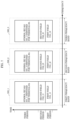
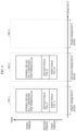
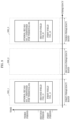
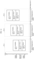
- An access point includes: a first interface that wirelessly communicates using a first band; a second interface that wirelessly communicates using a second band different than the first band; and a controller that selects one type of request to send (RTS)/clear to send (CTS) control from among three mutually different types using at least one of the first interface and the second interface, and carries out the selected one type of RTS/CTS control with a terminal.
- RTS request to send
- CTS clear to send
- a first type among the three mutually different types transmits a first RTS signal and receives a first CTS signal transmitted in response to the first RTS signal in one of the first band and the second band
- a second type among the three mutually different types transmits a second RTS signal destined for a plurality of terminals and receives a second CTS signal transmitted in response to the second RTS signal in one of the first band and the second band
- a third type among the three mutually different types transmits a third RTS signal destined for a plurality of terminals and receives a third CTS signal in response to the third RTS signal in each of the first band and the second band.
- An access point includes: a first interface that wirelessly communicates using a first band; a second interface that wirelessly communicates using a second band different than the first band; and a controller that selects one type of request to send (RTS)/clear to send (CTS) control from among three mutually different types using at least one of the first interface and the second interface, and carries out the selected one type of RTS/CTS control with a terminal.
- RTS request to send
- CTS clear to send
- a first type among the three mutually different types transmits a first RTS signal and receives a first CTS signal transmitted in response to the first RTS signal in one of the first band and the second band
- a second type among the three mutually different types transmits a second RTS signal destined for a plurality of terminals and receives a second CTS signal transmitted in response to the second RTS signal in one of the first band and the second band
- a third type among the three mutually different types transmits a third RTS signal destined for a plurality of terminals and receives a third CTS signal in response to the third RTS signal in each of the first band and the second band.
- the access point can secure an opportunity to communicate with a terminal, by using a selected one of the three types of RTS/CTS control. This makes it possible to contribute to the improvement of data transmission speed in communication between an access point and a terminal. In this way, the access point improves the data transmission speed of the communication system.
- the controller may transmit communication data using at least one resource unit in which the CTS signal was received.
- the access point can use, in communication with a terminal, a resource unit in which a CTS signal was received under RTS/CTS control.
- a resource unit in which a CTS signal was received there may be a plurality of resource units in which CTS signals are received.
- the access point can use at least one of the plurality of resource units in the communication with the terminal. In this way, the access point improves the data transmission speed of the communication system.
- a medium access control (MAC) address of a source of the third RTS signal transmitted in each of the first band and the second band may be the same.
- the access point transmits, in a plurality of bands, RTS signals that are destined for a plurality of terminals and include a common source MAC address.
- the access point improves the data transmission speed of the communication system in a simpler manner based on a more specific configuration.
- a communication method is executed by an access point including a first interface that wirelessly communicates using a first band and a second interface that wirelessly communicates using a second band different than the first band.
- the communication method includes: selecting one type of request to send (RTS)/clear to send (CTS) control from among three mutually different types using at least one of the first interface and the second interface; and carrying out the selected one type of RTS/CTS control with a terminal.
- RTS request to send
- CTS clear to send
- a first type among the three mutually different types transmits a first RTS signal destined for a single terminal and receives a first CTS signal transmitted in response to the first RTS signal in one of the first band and the second band
- a second type among the three mutually different types transmits a second RTS signal destined for a plurality of terminals and receives a second CTS signal transmitted in response to the second RTS signal in one of the first band and the second band
- a third type among the three mutually different types transmits a third RTS signal destined for a plurality of terminals and receives a third CTS signal in response to the third RTS signal in each of the first band and the second band.
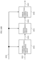
- the communication device illustrated in FIG. 1 is a communication device for transmitting and receiving modulated signals of first frequency band 201, which is the 2.4 GHz band, transmitting and receiving modulated signals of second frequency band 202, which is the 5 GHz band, and transmitting and receiving modulated signals of third frequency band 203, which is the 6 (or 7) GHz band, such as is illustrated in FIG. 2 .
- frequency is represented on the horizontal axis
- modulated signal power is represented on the vertical axis.
- antennas 104_1 and 105_1 and transceiver device 102_1 are for transmitting and receiving modulated signals of first frequency band 201
- antennas 104_2 and 105_2 and transceiver device 102_2 are for transmitting and receiving modulated signals of second frequency band 202
- antennas 104_3 and 105_3 and transceiver device 102_3 are for transmitting and receiving modulated signals of third frequency band 203.
- the communication device illustrated in FIG. 1 is configured as an access point (AP) device.
- the AP is a communication device that can communicate with one or more terminals, and, as a communications standard example, can transmit and receive modulated signals in accordance with the IEEE 802.11 communication method.
- a communication method related to IEEE 802.11 is disclosed in, for example, NPL 1.
- NPL 1 discloses transmission and reception using a carrier sense multiple access with collision avoidance (CSMA/CA) method in IEEE 802.11.
- CSMA/CA carrier sense multiple access with collision avoidance
- RTS request to send
- CTS clear to send
- an AP transmits an RTS signal.
- an AP is a device that can transmit the following modulated signals.
- a modulated signal destined for one terminal is transmitted using the first frequency band or the second frequency band.
- a modulated signal destined for one or more terminals is transmitted using the first frequency band or the second frequency band.
- a modulated signal destined for one or more terminals is transmitted using one or more of the first frequency band, the second frequency band and the third frequency band and using OFDM or OFDMA in each frequency band.
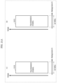
- FIG. 3A illustrates the configuration of a request to send (RTS) signal for the first transmitting method.
- RTS request to send
- time is represented on the horizontal axis.
- an AP having the configuration illustrated in FIG. 1 transmits the RTS illustrated in FIG. 3A .
- the RTS illustrated in FIG. 3A includes information indicating the address of the receive station (communication partner) and information indicating the address of the transmit station (in this example, the AP).
- the receive station address is information indicating the address of a single receive station (communication partner).
- FIG. 3B illustrates the configuration of a multi-user request to send (MU-RTS) signal for the second transmitting method.
- time is represented on the horizontal axis.
- an AP having the configuration illustrated in FIG. 1 transmits the MU-RTS illustrated in FIG. 3B .
- the MU-RTS illustrated in FIG. 3B includes information indicating the address of the receive station (communication partner) and information indicating the address of the transmit station (in this example, the AP).
- the receive station address is information indicating the address or addresses of one or more receive stations (communication partners) or information indicating the addresses of two or more receive stations (communication partners).
- FIG. 3C illustrates the configuration of a multi-channel multi-user request to send (MC-MU-RTS) signal for the third transmitting method.
- time is represented on the horizontal axis.
- an AP having the configuration illustrated in FIG. 1 transmits the MC-MU-RTS illustrated in FIG. 3C .
- the MC-MU-RTS illustrated in FIG. 3C includes information indicating the address of the receive station (communication partner) and information indicating the address of the transmit station (in this example, the AP).
- the receive station address is information indicating the address or addresses of one or more receive stations (communication partners) or information indicating the addresses of two or more receive stations (communication partners).
- Transceiver device 102_1 included in the AP having the configuration illustrated in FIG. 1 transmits and receives modulated signals of the first frequency band. Accordingly, when transmitting an RTS signal, transceiver device 102_1 transmits any one of the RTS illustrated in FIG. 3A , the MU-RTS illustrated in FIG. 3B , and the MC-MU-RTS illustrated in FIG. 3C .
- Transceiver device 102_2 included in the AP having the configuration illustrated in FIG. 1 transmits and receives modulated signals of the second frequency band. Accordingly, when transmitting an RTS signal, transceiver device 102_2 transmits any one of the RTS illustrated in FIG. 3A , the MU-RTS illustrated in FIG. 3B , and the MC-MU-RTS illustrated in FIG. 3C .
- Transceiver device 102_3 included in the AP having the configuration illustrated in FIG. 1 transmits and receives modulated signals of the third frequency band. Accordingly, when transmitting an RTS signal, transceiver device 102_3 transmits the MC-MU-RTS illustrated in FIG. 3C .
- the AP When transmitting the MC-MU-RTS illustrated in FIG. 3C , the AP does so using one or more of the first frequency band, the second frequency band, and the third frequency band. Accordingly, the following cases are conceivable.
- the AP transmits a first MC-MU-RTS in only the first frequency band.
- the AP transmits a second MC-MU-RTS in only the second frequency band.
- the AP transmits a third MC-MU-RTS in only the third frequency band.
- the AP transmits a first MC-MU-RTS in the first frequency band and transmits a third MC-MU-RTS in the third frequency band.
- the AP transmits a first MC-MU-RTS in the first frequency band, transmits a second MC-MU-RTS in the second frequency band, and transmits a third MC-MU-RTS in the third frequency band.
- the AP can achieve the advantageous effect that the following communication can be performed as a result of transmitting the MC-MU-RTS illustrated in FIG. 3C as described above: the AP can communicate with a single terminal in only the third frequency band; the AP can communicate with two or more terminals in only the third frequency band; and the AP can communicate with one or more terminals in the third frequency band and communicate with one or more terminals in another frequency band.
- a feature can be said to be that the AP does not transmit, in the third frequency band, the RTS signal illustrated in FIG. 3A or the MU-RTS signal illustrated in FIG. 3B .
- the AP is a device that can transmit the following modulated signals.
- a modulated signal destined for one terminal is transmitted using the first frequency band or the second frequency band.
- a modulated signal destined for one or more terminals is transmitted using one or more of the first frequency band, the second frequency band and the third frequency band and using OFDM or OFDMA in each frequency band.
- a given period or a modulated signal in a given period includes a symbol destined for one or more terminals (one or more resource units (RUs)). Examples include the frame configurations illustrated in FIG. 4A and FIG. 4B .
- frequency is (carriers are) represented on the vertical axis, and time is represented on the horizontal axis.
- symbol 401_1 destined for terminal #A (RU #A) is present in a first period.
- the number of frequency divisions is not limited to three.
- the frame configuration is not limited to the examples illustrated in FIG. 4A and FIG. 4B .
- the number of frequency divisions that is to say, the number of destination terminals may be 2, and, alternatively, may be four or more.
- the number of carriers assigned to each terminal may be different.
- time division into three RUs may be performed if time is represented on the vertical axis and frequency is represented on the horizontal axis in FIG. 4B .
- the number of slots in the case of time division that is to say, the number of destination terminals may be two or more, and the number of time slots assigned to each terminal may be different.
- a given period in a given period, one or more of the first frequency band, the second frequency band, and the third frequency band is used, and the given period includes one or more symbols destined for a terminal (i.e., one or more RU symbols).
- a frame has, for example, one of the frame configurations illustrated in FIG. 5A , FIG. 5B , FIG. 5C , FIG. 5D , FIG. 5E , FIG. 5F , FIG. 5G , FIG. 5H , FIG. 5I , FIG. 5J , and FIG. 5K .
- symbol (RU #A) 501_1 destined for terminal #A is present in the first period in the first frequency band
- symbol (RU #A) 501_2 destined for terminal #A is present in the first period in the second frequency band
- symbol (RU #A) 501_3 destined for terminal #A is present in the first period in the third frequency band.
- time is represented on the vertical axis
- frequency is (carriers are) represented on the horizontal axis.
- Elements that operate the same as those in FIG. 5A have the same reference signs, and repeated description thereof will be omitted.
- symbol (RU #A) 501_1 destined for terminal #A is present in the first period in the first frequency band
- symbol (RU #A) 501_2 destined for terminal #A is present in the first period in the second frequency band.
- symbol (RU #A) 501_1 destined for terminal #A is present in the first period in the first frequency band
- symbol (RU #A) 501_3 destined for terminal #A is present in the first period in the third frequency band.
- time is represented on the vertical axis
- frequency is (carriers are) represented on the horizontal axis.
- Elements that operate the same as those in FIG. 5A have the same reference signs, and repeated description thereof will be omitted.
- symbol (RU #A) 501_2 destined for terminal #A is present in the first period in the second frequency band
- symbol (RU #A) 501_3 destined for terminal #A is present in the first period in the third frequency band.
- time is represented on the vertical axis
- frequency is (carriers are) represented on the horizontal axis.
- Elements that operate the same as those in FIG. 5A have the same reference signs, and repeated description thereof will be omitted.
- data symbol 502_1 is present in the first period in the first frequency band
- data symbol 502_2 is present in the first period in the second frequency band
- data symbol 502_3 is present in the first period in the third frequency band.
- Data symbols 502_1, 502_2, and 502_3 are symbols for transmitting data. The configuration of data symbols 502_1, 502_2, and 502_3 will be described later with reference to FIG. 6A and FIG. 6B .
- time is represented on the vertical axis
- frequency is (carriers are) represented on the horizontal axis.
- Elements that operate the same as those in FIG. 5A and FIG. 5E have the same reference signs, and repeated description thereof will be omitted.
- data symbol 502_1 is present in the first period in the first frequency band
- data symbol 502_2 is present in the first period in the second frequency band
- Data symbols 502_1, 502_2, and 502_3 are symbols for transmitting data. The configuration of data symbols 502_1, 502_2, and 502_3 will be described later with reference to FIG. 6A and FIG. 6B .
- time is represented on the vertical axis
- frequency is (carriers are) represented on the horizontal axis.
- Elements that operate the same as those in FIG. 5A and FIG. 5E have the same reference signs, and repeated description thereof will be omitted.
- data symbol 502_1 is present in the first period in the first frequency band
- data symbol 502_3 is present in the first period in the third frequency band.
- Data symbols 502_1, 502_2, and 502_3 are symbols for transmitting data. The configuration of data symbols 502_1, 502_2, and 502_3 will be described later with reference to FIG. 6A and FIG. 6B .
- time is represented on the vertical axis
- frequency is (carriers are) represented on the horizontal axis.
- Elements that operate the same as those in FIG. 5A and FIG. 5E have the same reference signs, and repeated description thereof will be omitted.
- data symbol 502_1 is present in the first period in the first frequency band.
- Data symbols 502_1, 502_2, and 502_3 are symbols for transmitting data. The configuration of data symbols 502_1, 502_2, and 502_3 will be described later with reference to FIG. 6A and FIG. 6B .
- time is represented on the vertical axis
- frequency is (carriers are) represented on the horizontal axis.
- Elements that operate the same as those in FIG. 5A and FIG. 5E have the same reference signs, and repeated description thereof will be omitted.
- data symbol 502_2 is present in the first period in the second frequency band.
- Data symbols 502_1, 502_2, and 502_3 are symbols for transmitting data. The configuration of data symbols 502_1, 502_2, and 502_3 will be described later with reference to FIG. 6A and FIG. 6B .
- data symbol 502_3 is present in the first period in the third frequency band.
- Data symbols 502_1, 502_2, and 502_3 are symbols for transmitting data. The configuration of data symbols 502_1, 502_2, and 502_3 will be described later with reference to FIG. 6A and FIG. 6B .
- data symbol 502_X is configured of symbol (RU #X1) 601_1 destined for terminal #X1, symbol (RU #X2) 601_2 destined for terminal #X2, symbol (RU #X3) 601_3 destined for terminal #X3, and symbol (RU #X4) 601_4 destined for terminal #X4.
- FIG. 6B illustrates an example of a configuration of data symbol 502_X in an X th frequency band in FIG. 5E , FIG. 5F , FIG. 5G , FIG. 5H , FIG. 5I , FIG. 5J , and FIG. 5K .
- X is 1, 2, or 3.
- time is represented on the vertical axis
- frequency is (carriers are) represented on the horizontal axis.
- FIG. 6B illustrates frequency division into four RUs
- the number of frequency divisions is not limited to four.
- the configuration of data symbols 502_1, 502_2, and 502_3 are not limited to the examples illustrated in FIG. 6A and FIG. 6B .
- data symbols 502_2 and 502_3 may include symbols destined for the same terminal (for example, data symbols 502_2 and 502_3 may include symbols destined for terminal #A).
- any two or more of the frame configurations illustrated in, for example, FIG. 5A , FIG. 5B , FIG. 5C , FIG. 5D , FIG. 5E , FIG. 5F , FIG. 5G , FIG. 5H , FIG. 5I , FIG. 5J , and FIG. 5K are selection candidates, and the AP that transmits the modulated signal using the third transmitting method or the sixth transmitting method selects one frame configuration from among the selection candidates and transmits the modulated signal.
- the RTS illustrated in FIG. 3A includes information indicating the address of the receive station (communication partner) and information indicating the address of the transmit station (in this example, the AP).
- the receive station address is information indicating the address of one receive station (communication partner).
- the MC-MU-RTS illustrated in FIG. 3C includes information indicating the address of the receive station (communication partner) and information indicating the address of the transmit station (in this example, the AP).
- the receive station address is information indicating the address or addresses of one or more receive stations (communication partners) or information indicating the addresses of two or more receive stations (communication partners).
- Transceiver device 102_1 included in the AP having the configuration illustrated in FIG. 1 transmits and receives modulated signals of the first frequency band. Accordingly, when transmitting an RTS signal, transceiver device 102_1 transmits any one of the RTS illustrated in FIG. 3A , the MU-RTS illustrated in FIG. 3B , and the MC-MU-RTS illustrated in FIG. 3C .
- Transceiver device 102_2 included in the AP having the configuration illustrated in FIG. 1 transmits and receives modulated signals of the second frequency band. Accordingly, when transmitting an RTS signal, transceiver device 102_2 transmits any one of the RTS illustrated in FIG. 3A , the MU-RTS illustrated in FIG. 3B , and the MC-MU-RTS illustrated in FIG. 3C .
- Transceiver device 102_3 included in the AP having the configuration illustrated in FIG. 1 transmits and receives modulated signals of the third frequency band. Accordingly, when transmitting an RTS signal, transceiver device 102_3 transmits any one of the MU-RTS illustrated in FIG. 3B and the MC-MU-RTS illustrated in FIG. 3C .
- the AP When transmitting the MC-MU-RTS illustrated in FIG. 3C , the AP does so using one or more of the first frequency band, the second frequency band, and the third frequency band. Accordingly, the following cases are conceivable.
- the AP transmits a first MC-MU-RTS in only the first frequency band.
- the AP transmits a second MC-MU-RTS in only the second frequency band.
- an AP having the configuration illustrated in FIG. 1 transmits a modulated signal having any one of the frame configurations illustrated in FIG. 7 , FIG. 8 , FIG. 9 , FIG. 10 , FIG. 11 , FIG. 12 , FIG. 13 , and FIG. 14 .
- first field 701_2 is present in the first period in the second frequency band.
- First field 701_3 is present in the first period in the third frequency band.
- FIG. 6A and FIG. 6B are conceivable configurations of data symbol 502_3.
- Second field 702_1 is present in the second period in the first frequency band.
- Second field 702_3 is present in the second period in the third frequency band.
- FIG. 6A illustrates an example of a configuration of data symbol 502_X in the X th frequency band.
- X is 2.
- time is represented on the vertical axis
- frequency is (carriers are) represented on the horizontal axis.
- data symbol 502_X is configured of symbol (RU #X1) 601_1 destined for terminal #X1.
- symbol (RU #X1) 601_1 destined for terminal #X1 is not a symbol (RU #A) destined for terminal #A (however, symbol (RU #X1) 601_1 destined for terminal #X1 may conceivably be a symbol (RU #A) destined for terminal #A).
- the number of frequency divisions is not limited to four.
- the number of frequency divisions that is to say, the number of destination terminals may be 2 or more.
- the number of carriers assigned to each terminal may be different.
- the configuration of data symbol 502_2 is not limited to the examples illustrated in FIG. 6A and FIG. 6B .
- a feature may be that, in a given period, data symbols destined for the same terminal are present in the first frequency band and the second frequency band.
- first field 701_2 is present in the first period in the second frequency band.
- First field 701_3 is present in the first period in the third frequency band.
- first fields 701_2 and 701_3 include a symbol for the communication partner of the AP to perform signal detection, time synchronization, frequency synchronization, channel estimation, etc.
- a modulated signal is present in the first frequency band at a timing that is unrelated to the modulated signal of the second frequency band or the modulated signal of the third frequency band.
- first field 701_1, second field 702_1, and data symbol 502_1 are present.
- FIG. 6A and FIG. 6B are conceivable configurations of data symbol 502_1.
- FIG. 6A illustrates an example of a configuration of data symbol 502_X in the X th frequency band.
- X is 1.
- time is represented on the vertical axis
- frequency is (carriers are) represented on the horizontal axis.
- data symbol 502_X is configured of symbol (RU #X1) 601_1 destined for terminal #X1.
- symbol (RU #X1) 601_1 destined for terminal #X1 is not a symbol (RU #A) destined for terminal #A (however, symbol (RU #X1) 601_1 destined for terminal #X1 may conceivably be a symbol (RU #A) destined for terminal #A).
- FIG. 6B illustrates an example of a configuration of data symbol 502_X in the X th frequency band.
- X is 1.
- time is represented on the vertical axis
- frequency is (carriers are) represented on the horizontal axis.
- data symbol 502_X is configured of symbol (RU #X1) 601_1 destined for terminal #X1, symbol (RU #X2) 601_2 destined for terminal #X2, symbol (RU #X3) 601_3 destined for terminal #X3, and symbol (RU #X4) 601_4 destined for terminal #X4.
- data symbol 502_X does not include a symbol (RU #A) destined for terminal #A (data symbol 502_X may conceivably include a symbol (RU #A) destined for terminal #A).
- the number of frequency divisions is not limited to four.
- the number of frequency divisions that is to say, the number of destination terminals may be 2 or more.
- the number of carriers assigned to each terminal may be different.
- the configuration of data symbol 502_1 is not limited to the examples illustrated in FIG. 6A and FIG. 6B .
- time division into four RUs may be performed if time is represented on the vertical axis and frequency is represented on the horizontal axis in FIG. 6B .
- the number of slots in the case of time division that is to say, the number of destination terminals may be two or more, and the number of time slots assigned to each terminal may be different.
- data symbol 502_3 has either one of the frame configurations illustrated in FIG. 6A and FIG. 6B .
- a feature is that, in a given period, data symbols destined for the same terminal are present in the second frequency band and the third frequency band, and a data symbol destined for another terminal is present in the first frequency band.
- the timing at which first fields 701_1, 701_2, and 701_3 and second fields 702_1, 702_2, and 702_3 are transmitted is not limited to the example illustrated in FIG. 13 .
- a feature may be that, in a given period, data symbols destined for the same terminal are present in the first frequency band and the second frequency band.
- FIG. 14 illustrates one example of a frame configuration of a modulated signal transmitted by the AP. Elements in FIG. 14 that operate the same as those in FIG. 5 and FIG. 7 have the same reference signs, and repeated description thereof will be omitted.
- time is represented on the vertical axis
- frequency is (carriers are) represented on the horizontal axis.
- 500_1 indicates a frame configuration in the first frequency band
- 500_2 indicates a frame configuration in the second frequency band
- 500_3 indicates a frame configuration in the third frequency band.
- first field 701_1 is present in the first period in the first frequency band.
- first field 701_1 includes a symbol for the communication partner of the AP to perform signal detection, time synchronization, frequency synchronization, channel estimation, etc.
- Second field 701_1 is a field for transmitting control information to the communication partner of the AP, and includes, for example, information on the error encoding method used to generate data symbol 502_1, information on the modulation method of data symbol 502_1, and information on the transmitting method of data symbol 502_1.
- Data symbol 502_1 is present in the third period in the first frequency band.
- a modulated signal is present in the second frequency band at a timing that is unrelated to the modulated signal of the first frequency band. Moreover, a modulated signal is present in the third frequency band at a timing that is unrelated to the modulated signal of the first frequency band. Moreover, a modulated signal is present in the third frequency band at a timing that is unrelated to the modulated signal of the second frequency band.
- FIG. 6A and FIG. 6B are conceivable configurations of data symbols 502_1, 502_2, and 502_3.
- Data symbol 502_1 either has the configuration illustrated in FIG. 6A or the configuration illustrated in FIG. 6B .
- Data symbol 502_2 either has the configuration illustrated in FIG. 6A or the configuration illustrated in FIG. 6B .
- Data symbol 502_3 either has the configuration illustrated in FIG. 6A or the configuration illustrated in FIG. 6B .
- FIG. 6B illustrates an example of a configuration of data symbol 502_X in the X th frequency band.
- X is 1, 2, or 3.
- time is represented on the vertical axis
- frequency is (carriers are) represented on the horizontal axis.
- data symbol 502_X is configured of symbol (RU #X1) 601_1 destined for terminal #X1, symbol (RU #X2) 601_2 destined for terminal #X2, symbol (RU #X3) 601_3 destined for terminal #X3, and symbol (RU #X4) 601_4 destined for terminal #X4.
- the number of frequency divisions is not limited to four.
- the number of frequency divisions that is to say, the number of destination terminals may be 2 or more.
- the number of carriers assigned to each terminal may be different.
- time division into four RUs may be performed if time is represented on the vertical axis and frequency is represented on the horizontal axis in FIG. 6B .
- the number of slots in the case of time division that is to say, the number of destination terminals may be two or more, and the number of time slots assigned to each terminal may be different.
- This configuration may have the following feature.
- Data symbol 502_1 and data symbol 502_2 do not include symbols (RUs) destined for the same terminal
- data symbol 502_1 and data symbol 502_3 do not include symbols (RUs) destined for the same terminal
- data symbol 502_2 and data symbol 502_3 do not include symbols (RUs) destined for the same terminal.
- FIG. 7 , FIG. 8 , FIG. 9 , FIG. 10 , FIG. 11 , FIG. 12 , FIG. 13 , and FIG. 14 may include symbols other than those illustrated.
- these figures may include a preamble, a reference symbol, a control information symbol, a pilot symbol, a mid-amble, a null symbol (absence of a symbol), and/or a null carrier (absence of a symbol).
- FIG. 6A and FIG. 6B may include symbols other than those illustrated.
- these figures may include a preamble, a reference symbol, a control information symbol, a pilot symbol, a mid-amble, a null symbol (absence of a symbol), and/or a null carrier (absence of a symbol).
- any two or more of the frame configurations illustrated in, for example, FIG. 7 , FIG. 8 , FIG. 9 , FIG. 10 , FIG. 11 , FIG. 12 , FIG. 13 , and FIG. 14 are selection candidates, and the AP that transmits the modulated signal using the third transmitting method or the sixth transmitting method selects one frame configuration from among the selection candidates and transmits the modulated signal.
- Such an AP that transmits a modulated signal using the third transmitting method or the sixth transmitting method can be said to have the following characteristics.
- data symbol 502_1 when, in the third period, data symbol 502_1 is present in the first frequency band, data symbol 502_2 is present in the second frequency band, and data symbol 502_3 is present in the third frequency band, neither data symbol 502_1, data symbol 502_2, nor data symbol 502_3 has a configuration like that illustrated in FIG. 6B .
- FIG. 16 when, in the third period, data symbol 502_1 is present in the first frequency band and data symbol 502_2 is present in the second frequency band, neither data symbol 502_1 nor data symbol 502_2 has a configuration like that illustrated in FIG.
- Using a frame configuration having such a feature achieves the advantageous effect that data transmission speed in the modulated signal transmitted by the AP is improved. This will be described using, for example, the frame configuration illustrated in FIG. 15 as an example.
- data symbol 502_1 has a configuration like that in FIG. 6B .
- the number of symbols (RUs #X1) 601_1 destined for terminal #X1 is the greatest with respect to time.
- symbol (RU #X1) 601_1 destined for terminal #X1 is present, there is a time interval in which no symbol is present.
- data symbol 502_2 in the second frequency band and data symbol 502_3 in the third frequency band as well while symbol (RU #X1) 601_1 destined for terminal #X1 is present, there is a time interval in which no symbol is present.
- adverse effects resulting from there being a time interval in which no symbol is present while symbol (RU #X1) 601_1 destined for terminal #X1 is present affect even the second frequency band and the third frequency band, which adversely reduces data transmission speed.
- the AP transmits a modulated signal using the third transmitting method or the sixth transmitting method like in FIG. 7 , FIG. 8 , FIG. 9 , and FIG. 10 , it is possible to achieve the advantageous effect that high-speed data transmission can be realized with a specific terminal.
- the AP transmits a modulated signal using the third transmitting method or the sixth transmitting method like in FIG. 11 , FIG. 12 , and FIG. 13 , it is possible to achieve the advantageous effects that high-speed data transmission can be realized with a specific terminal, and multi-access, which enables data to be transmitted to a plurality of terminals, is possible.
- the above can be carried out where the A th frequency band is considered to be the first frequency band described above, and the B th frequency band is considered to be the second frequency band described above.
- the above can be carried out where the A th frequency band is considered to be the first frequency band described above, and the B th frequency band is considered to be the third frequency band described above.
- the above can be carried out where the A th frequency band is considered to be the second frequency band described above, and the B th frequency band is considered to be the third frequency band described above.
- the advantageous effects described in the present embodiment can be achieved by the AP transmitting the modulated signal described in the present embodiment and a terminal that receives the modulated signal performing processing, such as demodulation and error correction decoding, on the received modulated signal to obtain the data.
- the configuration of the access point is not limited to the example illustrated in FIG. 1 ; so long as the access point includes one or more or a plurality of transmit antennas for each frequency band, and generates and transmits one or more or a plurality of modulated signals for each frequency band, the present disclosure can be carried out.
- the device which includes the transmitting device, the receiving device, and the communication device is a communications and broadcast apparatus, such as a broadcast station, a base station, an access point, a terminal or a mobile phone, or a communication apparatus such as a television, a radio, or a personal computer.
- the transmitting device and the receiving device according to the present disclosure are each a device having a communication function, which is formed so as to be connectable via some interface to a device for executing an application in, for example, a television, a radio, a personal computer or a mobile phone.
- At least one of the field programmable gate array (FPGA) and the central processing unit (CPU) may be configured to download, via wired or wireless communication, some or all of the software required to implement the communication method described in the present disclosure. At least one of the FPGA and the CPU may be further configured to download, via wired or wireless communication, some or all of software required to perform updates.
- the downloaded software may be stored in storage, and based on the stored software, at least one of the FPGA and the CPU may be operated to implement the digital signal processing described in the present disclosure.
- a device including at least one of the FPGA and the CPU may connect to a communications modem over a wired or wireless connection, and the device and the communications modem may implement the communication method described in the present disclosure.
- a MIMO transmission scheme that transmits a plurality of modulated signals from a plurality of antennas may be used for one or more RUs among the RUs illustrated in FIG. 6B .
- the 2.4 GHz band includes a plurality of channels
- the 5 GHz includes a plurality of channels
- the 6 (or 7) GHz band includes a plurality of channels.
- the first frequency band is a first channel of the 2.4 GHz band
- the second frequency band is a second channel of the 2.4 GHz band
- the third frequency band is a third channel of the 2.4 GHz band.
- Controller 111 receives an input of received data group 110, determines one or more frequency bands for modulated signal transmissions from among the first frequency band, the second frequency band, and the third frequency band, and outputs control signal 112 including information indicating the determination. Controller 111 also outputs control signal 112 including information indicating the transmitting method, modulation method, and error correction coding method of each modulated signal to be transmitted.
- ( 1 ) and ( 2 ) indicate examples of bandwidths used when, for example, an AP (or terminal) transmits a modulated signal using the first frequency band.
- ( 1 ), ( 2 ), and ( 3 ) indicate examples of bandwidths used when, for example, an AP (or terminal) transmits a modulated signal using the third frequency band.
- transmission symbol 2101 which is a symbol included in the modulated signal, is a 80 MHz symbol.
- transmission symbol 2101 which is a symbol included in the modulated signal, is a 160 MHz symbol.
- Embodiment 2 in a given period, data symbols destined for the same terminal are present in the first frequency band, the second frequency band, and the third frequency band", or "in a given period, data symbols destined for the same terminal are present in the first frequency band and the second frequency band", or "in a given period, data symbols destined for the same terminal are present in the first frequency band and the third frequency band", or "in a given period, data symbols destined for the same terminal are present in the second frequency band and the third frequency band" are described.
- An example of RTS and CTS transmitting methods used in such cases will be described.
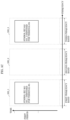
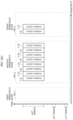
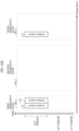
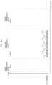
- FIG. 22A illustrates an example in which AP 1901 is transmitting RTSs to terminal 1902_1.
- frequency is represented on the horizontal axis and time is represented on the vertical axis.
- RTSs labeled 1_11 and 1_12, RTSs labeled 2_11, 2_12, 2_13, 2_14, 2_15, 2_16, 2_17, and 2_18, and RTSs labeled 3_11, 3_12, 3_13, and 3_14 are present in the A1 th period.
- AP 1901 transmits RTSs labeled 1_11 and 1_12 using first frequency band 500_1.
- Each of RTSs labeled 1_11 and 1_12 is present within a span of 20 MHz, for example.
- RTS labeled 1_11 is present in the first channel of first frequency band 500_1
- RTS labeled 1_12 is present in the second channel of first frequency band 500_1.
- first frequency band 500_1 may include other channels, and AP 1901 may use a channel other than the first channel or the second channel to transmit an RTS.
- AP 1901 transmits RTSs labeled 2_11, 2_12, 2_13, 2_14, 2_15, 2_16, 2_17, and 2_18 using second frequency band 500_2.
- RTSs labeled 2_11, 2_12, 2_13, 2_14, 2_15, 2_16, 2_17, and 2_18 is present in a span of 20 MHz, for example.
- each of RTSs labeled 1_11 and 1_12, RTSs labeled 2_11, 2_12, 2_13, 2_14, 2_15, 2_16, 2_17, and 2_18, and RTSs labeled 3_11, 3_12, 3_13, and 3_14 includes information indicating the address of a single terminal (1902_1).
- Terminal 1902_1 receives the RTSs illustrated in FIG. 22A that are transmitted by AP 1901. Then, in response to receiving the RTSs, terminal 1902_1 enters a state in which the terminal has completed preparation for reception in the first channel, the second channel, the third channel, the fourth channel, the fifth channel, the sixth channel, the seventh channel, and the eighth channel of second frequency band 500_2, and the first channel and the second channel of third frequency band 500_3.
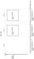
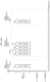
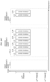
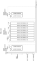
- FIG. 22B illustrates an example in which terminal 1902_1 is transmitting CTSs to AP 1901. In FIG. 22B , frequency is represented on the horizontal axis and time is represented on the vertical axis. As illustrated in FIG.
- CTSs labeled 2_21, 2_22, 2_23, 2_24, 2_25, 2_26, 2_27, and 2_28, and CTSs labeled 3_21 and 3_22 are present in the A2 th period.
- Terminal 1902_1 transmits CTSs labeled 2_21, 2_22, 2_23, 2_24, 2_25, 2_26, 2_27, and 2_28 using second frequency band 500_2.
- Each of CTSs labeled 2_21, 2_22, 2_23, 2_24, 2_25, 2_26, 2_27, and 2_28 is present in a span of 20 MHz, for example.
- CTS labeled 2_21 is present in the first channel of second frequency band 500_2, CTS labeled 2_22 is present in the second channel of second frequency band 500_2, CTS labeled 2_23 is present in the third channel of second frequency band 500_2, CTS labeled 2_24 is present in the fourth channel of second frequency band 500_2, CTS labeled 2_25 is present in the fifth channel of second frequency band 500_2, CTS labeled 2_26 is present in the sixth channel of second frequency band 500_2, CTS labeled 2_27 is present in the seventh channel of second frequency band 500_2, and CTS labeled 2_28 is present in the eighth channel of second frequency band 500_2.
- second frequency band 500_2 may include other channels.
- AP 1901 receives the CTSs illustrated in FIG. 22B that are transmitted by terminal 1902_1. Then, in response to receiving the CTSs, AP 1901 determines to transmit symbol groups including data symbols in the first channel, second channel, third channel, fourth channel, fifth channel, sixth channel, seventh channel, and eighth channel of second frequency band 500_2 and in the first channel and the second channel of third frequency band 500_3.
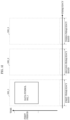
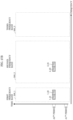
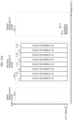
- FIG. 22C illustrates an example in which AP 1901 is transmitting symbol groups including data symbols to terminal 1902_1. In FIG. 22C , frequency is represented on the horizontal axis and time is represented on the vertical axis. As illustrated in FIG.
- AP 1901 transmits symbol groups labeled 3_31 and 3_32 using third frequency band 500_3.
- Each of symbol groups labeled 3_31 and 3_32 is present within a span of 80 MHz, for example.
- Symbol group labeled 3_31 is present in the first channel of third frequency band 500_3, and symbol group labeled 3_32 is present in the second channel of third frequency band 500_3.
- third frequency band 500_3 may include other channels.
- Terminal 1902_1 receives the RTSs illustrated in FIG. 22A that are transmitted by AP 1901. Then, in response to receiving the RTSs, terminal 1902_1 enters a state in which the terminal has completed preparation for reception in the first channel of first frequency band 500_1, the first channel, the second channel, the third channel, and the fourth channel of second frequency band 500_2, and the first channel of third frequency band 500_3.
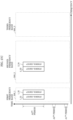
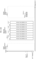
- FIG. 23A illustrates an example in which terminal 1902_1 is transmitting CTSs to AP 1901.
- frequency is represented on the horizontal axis and time is represented on the vertical axis.
- CTS labeled 1_21, CTSs labeled 2_21, 2_22, 2_23, and 2_24, and CTS labeled 3_21 are present in the A2 th period.
- Terminal 1902_1 transmits CTS labeled 1_21 using first frequency band 500_1.
- CTS labeled 1_21 is present within a span of 20 MHz, for example.
- CTS labeled 1_21 is present in the first channel of first frequency band 500_1.
- first frequency band 500_1 may include other channels.
- Terminal 1902_1 transmits CTSs labeled 2_21, 2_22, 2_23, and 2_24 using second frequency band 500_2.
- Each of CTSs labeled 2_21, 2_22, 2_23, and 2_24 is present in a span of 20 MHz, for example.
- CTS labeled 2_21 is present in the first channel of second frequency band
- CTS labeled 2_22 is present in the second channel of second frequency band 500_2
- CTS labeled 2_23 is present in the third channel of second frequency band 500_2
- CTS labeled 2_24 is present in the fourth channel of second frequency band 500_2.
- second frequency band 500_2 may include other channels.
- AP 1901 receives the CTSs illustrated in FIG. 23A that are transmitted by terminal 1902_1. Then, in response to receiving the CTSs, AP 1901 determines to transmit symbol groups including data symbols in the first channel of first frequency band 500_1, the first channel, the second channel, the third channel, and the fourth channel of second frequency band 500_2, and the first channel of third frequency band 500_3.
- FIG. 23B illustrates an example in which AP 1901 is transmitting symbol groups including data symbols to terminal 1902_1.
- frequency is represented on the horizontal axis and time is represented on the vertical axis.
- symbol group labeled 1_31, symbol groups labeled 2_31, 2_32, 2_33, and 2_34, and symbol group labeled 3_31 are present in the A3 th period.
- AP 1901 transmits symbol groups labeled 2_31, 2_32, 2_33, and 2_34 using second frequency band 500_2.
- Each of symbol groups labeled 2_31, 2_32, 2_33, and 2_34 is present in a span of 20 MHz, for example.
- Symbol group labeled 2_31 is present in the first channel of second frequency band 500_2
- symbol group labeled 2_32 is present in the second channel of second frequency band 500_2
- symbol group labeled 2_33 is present in the third channel of second frequency band 500_2
- symbol group labeled 2_34 is present in the fourth channel of second frequency band 500_2.
- second frequency band 500_2 may include other channels.
- FIG. 22A An example in which AP 1901 transmits RTSs to terminal 1902_1 is illustrated in FIG. 22A . As FIG. 22A has already been described, detailed repeated description thereof will be omitted.
- Terminal 1902_1 receives the RTSs illustrated in FIG. 22A that are transmitted by AP 1901. Then, in response to receiving the RTSs, terminal 1902_1 enters a state in which the terminal has completed preparation for reception in the first channel and the second channel of first frequency band 500_1, and the first channel, the second channel, the third channel, and the fourth channel of second frequency band 500_2.
- frequency is represented on the horizontal axis and time is represented on the vertical axis.
- CTSs labeled 1_21 and 1_22, and CTSs labeled 2_21, 2_22, 2_23, and 2_24 are present in the A2 th period.
- Terminal 1902_1 transmits CTSs labeled 2_21, 2_22, 2_23, and 2_24 using second frequency band 500_2.
- Each of CTSs labeled 2_21, 2_22, 2_23, and 2_24 is present in a span of 20 MHz.
- CTS labeled 2_21 is present in the first channel of second frequency band
- CTS labeled 2_22 is present in the second channel of second frequency band 500_2
- CTS labeled 2_23 is present in the third channel of second frequency band 500_2
- CTS labeled 2_24 is present in the fourth channel of second frequency band 500_2.
- second frequency band 500_2 may include other channels.
- each of RTSs labeled 2_11, 2_12, 2_13, 2_14, 2_15, 2_16, 2_17, and 2_18, and RTSs labeled 3_13 and 3_14 includes information indicating the address of a single terminal (1902_1).
- CTSs labeled 2_21, 2_22, 2_23, 2_24, 2_25, 2_26, 2_27, and 2_28, and CTSs labeled 3_23 and 3_24 are present in the A2 th period.
- Terminal 1902_1 transmits CTSs labeled 2_21, 2_22, 2_23, 2_24, 2_25, 2_26, 2_27, and 2_28 using second frequency band 500_2.
- Each of CTSs labeled 2_21, 2_22, 2_23, 2_24, 2_25, 2_26, 2_27, and 2_28 is present in a span of 20 MHz, for example.
- Terminal 1902_1 transmits CTSs labeled 3_23 and 3_24 using third frequency band 500_3.
- Each of CTSs labeled 3_23 and 3_24 is present within a span of 80 MHz, for example.
- CTS labeled 3_23 is present in the third channel of third frequency band 500_3, and CTS labeled 3_24 is present in the fourth channel of third frequency band 500_3.
- third frequency band 500_3 may include other channels.
- Symbol group labeled 2_31 is present in the first channel of second frequency band 500_2, symbol group labeled 2_32 is present in the second channel of second frequency band 500_2, symbol group labeled 2_33 is present in the third channel of second frequency band 500_2, symbol group labeled 2_34 is present in the fourth channel of second frequency band 500_2, symbol group labeled 2_35 is present in the fifth channel of second frequency band 500_2, symbol group labeled 2_36 is present in the sixth channel of second frequency band 500_2, symbol group labeled 2_37 is present in the seventh channel of second frequency band 500_2, and symbol group labeled 2_38 is present in the eighth channel of second frequency band 500_2.
- second frequency band 500_2 may include other channels.
- FIG. 27A illustrates an example in which AP 1901 is transmitting RTSs to terminal 1902_1.
- frequency is represented on the horizontal axis and time is represented on the vertical axis.
- RTSs labeled 1_11 and 1_12, and RTSs labeled 2_13, 2_14, 2_15, and 2_16 are present in the A1 th period.
- AP 1901 transmits RTSs labeled 1_11 and 1_12 using first frequency band 500_1.
- Each of RTSs labeled 1_11 and 1_12 is present within a span of 20 MHz, for example.
- RTS labeled 1_11 is present in the first channel of first frequency band 500_1
- RTS labeled 1_12 is present in the second channel of first frequency band 500_1.
- first frequency band 500_1 may include other channels, and AP 1901 may use a channel other than the first channel or the second channel to transmit an RTS.
- RTS labeled 2_13 is present in the third channel of second frequency band 500_2
- RTS labeled 2_14 is present in the fourth channel of second frequency band 500_2
- RTS labeled 2_15 is present in the fifth channel of second frequency band 500_2
- RTS labeled 2_16 is present in the sixth channel of second frequency band 500_2.
- second frequency band 500_2 may include other channels, and AP 1901 may use a channel other than the first through eighth channels to transmit an RTS.
- AP 1901 transmits symbol groups labeled 3_33 and 3_34 using third frequency band 500_3.
- Each of symbol groups labeled 3_33 and 3_34 is present within a span of 80 MHz, for example.
- Symbol group labeled 3_33 is present in the third channel of third frequency band 500_3, and symbol group labeled 3_34 is present in the fourth channel of third frequency band 500_3.
- third frequency band 500_3 may include other channels.
- AP 1901 transmits symbol groups labeled 2_31, 2_32, 2_33, 2_34, 2_35, 2_36, 2_37, and 2_38 using second frequency band 500_2.
- Each of symbol groups labeled 2_31, 2_32, 2_33, 2_34, 2_35, 2_36, 2_37, and 2_38 is present in a span of 20 MHz, for example.
- the RTSs illustrated in FIG. 31A are characterized in that they include only the address of a specific terminal.
- the configuration method of the channels used in the first frequency band, the configuration method of the channels used in the second frequency band, and the configuration method of the channels used in the third frequency band are not limited to the above examples. Accordingly, the embodiment may be implemented in the same manner even with a configuration method other than the examples illustrated in FIG. 31A , FIG. 31B , and FIG. 31C . Since the AP is communicating with a terminal other than the above terminal in another frequency band, namely second frequency band 500_2, it is possible to achieve the advantageous effect that data transmission speed in the communication system can be improved.
- the AP may be currently communicating in third frequency band 500_3, and may transmit data symbols to a plurality of terminals using first frequency band 500_1.
- the RTSs transmitted by AP 1901 using first frequency band 500_1 include the addresses of a plurality of terminals.
- frequency division such as illustrated in FIG. 6B
- time division such as illustrated in FIG. 34
- time division such as illustrated in FIG. 34
- the AP may transmit the symbols destined for the plurality of terminals, and, alternatively, two or more regions comprised of time and frequency may be provided, and the AP may transmit the symbols destined for the plurality of terminals, such as illustrated in FIG. 35 .
- time is represented on the horizontal axis
- frequency is represented on the vertical axis.
- frequency is represented on the horizontal axis and time is represented on the vertical axis.
- operations may be operations performed by a base station, a repeater, a terminal, a communication device, a personal computer, or a mobile phone.
- operations may be operations performed by an AP, a base station, a repeater, a communication device, a personal computer, or a mobile phone.
- multi-band communication and multichannel communication will be described.
- multi-band communication and multichannel communication are defined as follows.
- Multichannel communication is the simultaneous reception of a plurality of modulated signals transmitted by one or more communication partners, i.e., one or more communication devices (for example, access points (APs)), by a first communication device (for example, a terminal).
- These plurality of modulated signals include modulated signals in a plurality of channels of the first frequency band (for example, the first channel and the second channel of the 5 GHz band).
- the first communication device may simultaneously communicate with the one or more communication devices that are the communication partners using a plurality of channels of the first frequency band. Examples are given in Embodiment 1 through Embodiment 3.
- the present embodiment will be described using a wireless LAN communication system based on the IEEE 802.11 standard as an example.
- MAC wireless LAN medium access control
- MAC frames There are three types of MAC frames: a management frame; a control frame; and a data frame.
- management frame will be described. Examples of management frames are given below.
- a frame for informing surrounding wireless communication devices of network information is
- a frame for disconnecting communication A frame for disconnecting communication.
- a frame for performing authentication between wireless communication devices is a frame for performing authentication between wireless communication devices.
- a universal frame for additional functions is provided.
- RTS Request to send
- a frame for requesting data transmission A frame for requesting data transmission.
- a frame for transmitting that the wireless communication device specified in the RTS is clear to transmit.
- a frame for acknowledging and responding to normal receipt of data A frame for acknowledging and responding to normal receipt of data.
- Block ACK request frame
- a data frame is a frame for transmitting user data.
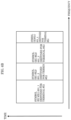
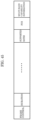
- FIG. 36 An example of a configuration of a data frame according to the IEEE 802.11 standard is illustrated in FIG. 36 .
- the values in FIG. 36 indicate the data length of the field they are above, and are in units of bytes.
- TABLE 1 shows how the Address fields of the data frame are used.
- TABLE 1 Function ToDS FromDS Address 1 (Receiver) Address 2 (Transmitter) Address 3 Address 4 IBSS 0 0 Destination address (DA) Source address (SA) BSSID Not used To AP (infrastructure) 1 0 BSSID Source address (SA) Destination address (DA) Not used From AP (infrastructure) 0 1 Destination address (DA) BSSID Source address (SA) Not used WDS (bridge) 1 1 Receiver address (RA) Transmitter address (TA) Destination address (DA) Source address (SA)
- IBSS Independent Basic Service Set
- AP stands for Access Point
- WDS Wireless Distribution System
- DS stands for Distribution System
- BSSID Basic Service Set Identifier (ID)
- SA Source Address
- RA Receiver Address
- TA Transmitter Address
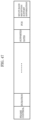
- FIG. 37 An example of a configuration of a beacon frame according to the IEEE 802.11 standard is illustrated in FIG. 37 .
- the values in FIG. 37 indicate the data length of the field they are above, and are in units of bytes.
- a beacon frame includes the following:
- a beacon frame also includes the following:
- FIG. 38 An example of a configuration of a probe request frame according to the IEEE 802.11 standard is illustrated in FIG. 38 .
- the values in FIG. 38 indicate the data length of the field they are above, and are in units of bytes.
- a probe request frame also includes the following:
- a probe request frame also includes the following: 4 bytes long FCS (field).
- the DA is typically the MAC address of the AP
- the SA and BSSID are typically the MAC address of the terminal.
- the SSID is typically the SSID of the AP.
- FIG. 39 An example of a configuration of a probe response frame according to the IEEE 802.11 standard is illustrated in FIG. 39 .
- the values in FIG. 39 indicate the data length of the field they are above, and are in units of bytes.
- a probe response frame also includes the following:
- the DA In a probe response frame transmitted by an AP, the DA is typically the MAC address of a terminal, and the SA and BSSID are typically the MAC address of the AP.
- the SSID is typically the SSID of the AP.
- an association request frame includes the following:
- AP #2 labeled 4201_2 uses a 2_1 th SSID for the 2.4 GHz.
- transceiver device 102_2 performs processing for receiving 5 GHz band modulated signals. Accordingly, in the example illustrated in FIG. 42 , a beacon frame transmitted by AP #1 labeled 4201_1 and a beacon frame transmitted by AP #3 labeled 4201_3 are received, and data is obtained from the beacon frames.
- the Multi-band Transmission Capability Information (field) in the association request frame on the 2.4 GHz band is information indicating that the terminal is not capable of multi-band modulated signal transmission.
- the Multi-band Transmission Capability Information (field) in the association request frame on the 6 GHz band is information indicating that the terminal is not capable of multi-band modulated signal transmission.
- the Multi-band Reception Capability Information (field) of the association request frame on the 5 GHz band is information indicating that terminal #1 labeled 4202_1 can receive, i.e., demodulate a multi-band modulated signal transmitted by a communication partner.
- the Multi-band Reception Capability Information (field) of the association request frame on the 2.4 GHz band is information indicating that the terminal cannot receive, i.e., cannot demodulate a multi-band modulated signal transmitted by a communication partner.
- the Multi-band Reception Capability Information (field) of the association request frame on the 5 GHz band is information indicating that the terminal cannot receive, i.e., cannot demodulate a multi-band modulated signal transmitted by a communication partner.
- AP #1 labeled 4201_1 illustrated in FIG. 42 receives the association request frame transmitted on the 2.4 GHz band (i.e., the 2.4 GHz band modulated signal transmitted) by terminal #1 labeled 4202_1, the association request frame transmitted on the 5 GHz band (i.e., the 5 GHz band modulated signal transmitted) by terminal #1 labeled 4202_1, and the association request frame transmitted on the 6 GHz band (i.e., the 6 GHz band modulated signal transmitted) by terminal #1 labeled 4202_1.
- the association request frame transmitted on the 2.4 GHz band i.e., the 2.4 GHz band modulated signal transmitted
- the 5 GHz band i.e., the 5 GHz band modulated signal transmitted
- 6 GHz band i.e., the 6 GHz band modulated signal transmitted
- Transceiver device 102_2 in AP #1 labeled 4201_1 illustrated in FIG. 42 receives an input of control signal 112, and generates and outputs a modulated signal of an association response frame on the 5 GHz band from the data of the association response frame on the 5 GHz band that is included in control signal 112.
- the modulated signal of an association response frame on the 5 GHz band is output as radio waves from antenna 103_2.
- Transceiver device 102_3 in AP #1 labeled 4201_1 illustrated in FIG. 42 receives an input of control signal 112, and generates and outputs a modulated signal of an association response frame on the 6 GHz band from the data of the association response frame on the 6 GHz band that is included in control signal 112.
- the modulated signal of an association response frame on the 6 GHz band is output as radio waves from antenna 103_3.
- the Multi-band Transmission Support Information (field) illustrated in FIG. 46 includes information indicating whether an AP having the configuration in FIG. 1 supports or does not support multi-band modulated signal transmission.
- the Multi-band Transmission Support Information (field) in the association response frame on the 2.4 GHz band is information indicating that AP #1 labeled 4201_1 is capable of multi-band modulated signal transmission.
- the Multi-band Transmission Support Information (field) in the association response frame on the 5 GHz band is information indicating that AP #1 labeled 4201_1 is capable of multi-band modulated signal transmission.
- the Multi-band Transmission Support Information (field) in the association response frame on the 6 GHz band is information indicating that AP #1 labeled 4201_1 is capable of multi-band modulated signal transmission.
- AP #1 labeled 4201_1 in FIG. 42 sets the Multi-band Reception Support Information (field) illustrated in FIG. 46 as follows.
- the Multi-band Reception Support Information (field) of the association response frame on the 5 GHz band is information indicating that AP #1 labeled 4201_1 can receive, i.e., demodulate a multi-band modulated signal transmitted by a communication partner.
- the Multi-band Reception Support Information (field) of the association response frame on the 2.4 GHz band is information indicating that the AP cannot receive, i.e., cannot demodulate a multi-band modulated signal transmitted by a communication partner.
- FIG. 47 illustrates a configuration of an association response frame transmitted by an AP that differs from the example illustrated in FIG. 46 .
- FIG. 47 differs from FIG. 46 in that the frame includes Multi-band Communication Support Information (field) instead of the Multi-band Transmission Support Information (field) and the Multi-band Reception Support Information (field).
- field Multi-band Communication Support Information
- the Multi-band Communication Support Information (field) in FIG. 47 includes information indicating whether an AP having the configuration illustrated in FIG. 1 is capable or incapable of communication via multi-band modulated signals.
- the Multi-band Communication Support Information (field) illustrated in FIG. 47 and included in the association response frame on the 2.4 GHz band is information indicating that AP #1 labeled 4201_1 is capable of communication via multi-band modulated signals.
- the Multi-band Communication Support Information (field) illustrated in FIG. 47 and included in the association response frame on the 5 GHz band is information indicating that the AP is not capable of communication via multi-band modulated signals.
- the Multi-band Communication Support Information (field) illustrated in FIG. 47 and included in the association response frame on the 6 GHz band is information indicating that the AP is not capable of communication via multi-band modulated signals.
- Multi-band Transmission Support Information field
- Multi-band Reception Support Information field
- Information other than the information depicted in FIG. 46 may be included in the association response frame.
- information other than the information depicted in FIG. 47 may be included in the association response frame.
- Terminal #1 labeled 4202_1 illustrated in FIG. 42 receives the association response frame transmitted on the 2.4 GHz band (i.e., the 2.4 GHz band modulated signal transmitted) by AP #1 labeled 4201_1, the association response frame transmitted on the 5 GHz band (i.e., the 5 GHz band modulated signal transmitted) by AP #1 labeled 4201_1, and the association response frame transmitted on the 6 GHz band (i.e., the 6 GHz band modulated signal transmitted) by AP #1 labeled 4201_1.
- transceiver device 102_1 receives an input of the modulated signal including the association response frame on the 2.4 GHz band received by antenna 105_1, demodulates the modulated signal, and obtains the data of the association response frame on the 2.4 GHz band.
- Transceiver device 102_2 receives an input of the modulated signal including the association response frame on the 5 GHz band received by antenna 105_2, demodulates the modulated signal, and obtains the data of the association response frame on the 5 GHz band.
- Transceiver device 102_3 receives an input of the modulated signal including the association response frame on the 6 GHz band received by antenna 105_3, demodulates the modulated signal, and obtains the data of the association response frame on the 6 GHz band.
- FIG. 48 illustrates a configuration of a beacon frame transmitted by an AP that differs from the example illustrated in FIG. 37 .
- the beacon frame illustrated in FIG. 48 includes a Multi-band Transmission Support Information (field) and a Multi-band Reception Support Information (field), in addition to the following illustrated in FIG.
- the Multi-band Reception Support Information (field) illustrated in FIG. 48 includes information indicating whether an AP having the configuration in FIG. 1 is capable or incapable of reception when a communication partner transmits a multi-band modulated signal.
- the Multi-band Transmission Support Information (field) in the beacon frame on the 5 GHz band is information indicating that AP #1 labeled 4201_1 is capable of multi-band modulated signal transmission.
- the Multi-band Transmission Support Information (field) in the beacon frame on the 2.4 GHz band is information indicating that the AP does not support multi-band modulated signal transmission.
- the Multi-band Transmission Support Information (field) in the beacon frame on the 5 GHz band is information indicating that the AP does not support multi-band modulated signal transmission.
- the Multi-band Transmission Support Information (field) in the beacon frame on the 6 GHz band is information indicating that the AP does not support multi-band modulated signal transmission.
- the Multi-band Reception Support Information (field) of the beacon frame on the 2.4 GHz band is information indicating that AP #1 labeled 4201_1 can receive, i.e., demodulate a multi-band modulated signal transmitted by a communication partner.
- FIG. 49 illustrates a configuration of a beacon frame transmitted by an AP that differs from the example illustrated in FIG. 48 .
- FIG. 49 differs from FIG. 48 in that the frame includes Multi-band Communication Support Information (field) instead of the Multi-band Transmission Support Information (field) and the Multi-band Reception Support Information (field).
- field Multi-band Communication Support Information
- the Multi-band Communication Support Information (field) in FIG. 49 includes information indicating whether an AP having the configuration illustrated in FIG. 1 is capable or incapable of communication via multi-band modulated signals.
- Controller 111 receives an input of received data group 100, and obtains the data of the beacon frames. Controller 111 outputs the obtained beacon frame data as beacon frame information signal 4301.
- Setter 4303 receives an input of settings signal 4302.
- Settings signal 4302 includes information indicating the SSID of the AP that a terminal in FIG. 43 (terminal #1 labeled 4202_1 in this example) is to connect to.
- settings signal 4302 includes information indicating the 1_1 th SSID, the 1_2 th SSID, and the 1_3 th SSID, and setter 4303 performs the following processes based on the information indicating the 1_1 th SSID, the 1_2 th SSID, and the 1_3 th SSID.
- setter 4303 determines that multi-band communication is not possible via the AP corresponding to the 1_1 th SSID and the AP corresponding to the 1_2 th SSID.
- setter 4303 determines that multi-band communication is not possible via the AP corresponding to the 1_1 th SSID and the AP corresponding to the 1_3 th SSID.
- setter 4303 determines that multi-band communication is possible via the AP corresponding to the 1_2 th SSID and the AP corresponding to the 1_3 th SSID. Note that setter 4303 may determine the AP corresponding to the 1_2 th SSID and the AP corresponding to the 1_3 th SSID to be the same device.
- setter 4303 may obtain the first multi-band related information, the second multi-band related information, and the third multi-band related information, and search for an AP that can communicate using multichannel communication.
- setter 4303 specifies communication with a 2.4 GHz band AP via settings signal 4302.
- Setter 4303 then obtains, via the first multi-band related information, information indicating that multi-band communication is possible on the first frequency band (2.4 GHz band). Based on this, setter 4303 searches for an SSID capable of multi-band communication on the second frequency band (5 GHz band) or the third frequency band (6 GHz band).
- setter 4303 obtains third multi-band related information from the third frequency band beacon frame, and searches for a beacon frame having information indicating that multi-band communication is possible. As described above, setter 4303 checks SSIDs, SAs, and BSSIDs to detect an AP (SSID) on the 6 GHz band that is capable of performing multi-band communication with the 2.4 GHz band.
- SSID AP
- the terminal is exemplified as having the configuration illustrated in FIG. 43 and the AP is exemplified as having the configuration illustrated in FIG. 1 , but the configurations of the terminal and the AP are not limited to those illustrated in FIG. 43 and FIG. 1 .
- the terminal and AP may use a transmission method such as multiple-input multiple-output (MIMO), multiple-input single-output (MISO), or single-input multiple-output (SIMO) for the first frequency band transmitting method or the second frequency band transmitting method or the third frequency band transmitting method.
- MIMO multiple-input multiple-output
- MISO multiple-input single-output
- SIMO single-input multiple-output
- transceiver devices 102_1, 102_2, and 102_3 in FIG. 43 and FIG. 1 may be connected to a plurality of transmit antennas and may be connected to a plurality of receive antennas.
- transceiver devices 102_1, 102_2, and 102_3 transmit a plurality of modulated signals from a plurality of antennas at the same frequency (same frequency band), at the same time.
- the AP and the terminal are exemplified as being capable of communicating on three frequency bands in the present embodiment, so long as the AP and the terminal support communicating on two or more frequency bands, when the present embodiment is carried out in the same manner, multi-band communication is possible. Accordingly, although the configuration example of the AP illustrated in FIG. 1 includes transceiver devices 102_1, 102_2, and 102_3, the AP may have a configuration in which any one of the transceiver devices 102_1, 102_2, and 102_3 is omitted when, for example, the AP is capable of communicating on two frequency bands. When the AP is capable of communicating on four or more frequency bands, the configuration illustrated in FIG. 1 may additionally include one or more transceiver devices.
- the terminal illustrated in FIG. 43 includes transceiver devices 102_1, 102_2, and 102_3, the terminal may have a configuration in which any one of the transceiver devices 102_1, 102_2, and 102_3 is omitted when, for example, the AP is capable of communicating on two frequency bands.
- the configuration illustrated in FIG. 1 may additionally include one or more transceiver devices.
- the present embodiment is merely one example; for example, the AP and the terminal may be switched and the embodiment may be carried out in the same manner.
- the terms "AP" and "terminal” are used, but the AP may be referred to as a base station, a communication device, a terminal, a broadcast station, a node, etc., and the embodiment may be carried out, and the terminal may be referred to as a communication device, an access point, a node, a base station, etc., and the embodiment may be carried out.
Landscapes
- Engineering & Computer Science (AREA)
- Computer Networks & Wireless Communication (AREA)
- Signal Processing (AREA)
- Mobile Radio Communication Systems (AREA)
Applications Claiming Priority (6)
| Application Number | Priority Date | Filing Date | Title |
|---|---|---|---|
| US201862695273P | 2018-07-09 | 2018-07-09 | |
| US201862701184P | 2018-07-20 | 2018-07-20 | |
| US201862716009P | 2018-08-08 | 2018-08-08 | |
| US201862756832P | 2018-11-07 | 2018-11-07 | |
| PCT/JP2019/026753 WO2020013088A1 (ja) | 2018-07-09 | 2019-07-04 | アクセスポイント及び通信方法 |
| EP19833171.2A EP3823403B1 (de) | 2018-07-09 | 2019-07-04 | Zugangspunkt und kommunikationsverfahren |
Related Parent Applications (2)
| Application Number | Title | Priority Date | Filing Date |
|---|---|---|---|
| EP19833171.2A Division EP3823403B1 (de) | 2018-07-09 | 2019-07-04 | Zugangspunkt und kommunikationsverfahren |
| EP19833171.2A Division-Into EP3823403B1 (de) | 2018-07-09 | 2019-07-04 | Zugangspunkt und kommunikationsverfahren |
Publications (2)
| Publication Number | Publication Date |
|---|---|
| EP4398673A2 true EP4398673A2 (de) | 2024-07-10 |
| EP4398673A3 EP4398673A3 (de) | 2024-09-25 |
Family
ID=69141846
Family Applications (2)
| Application Number | Title | Priority Date | Filing Date |
|---|---|---|---|
| EP24177201.1A Pending EP4398673A3 (de) | 2018-07-09 | 2019-07-04 | Zugangspunkt und kommunikationsverfahren |
| EP19833171.2A Active EP3823403B1 (de) | 2018-07-09 | 2019-07-04 | Zugangspunkt und kommunikationsverfahren |
Family Applications After (1)
| Application Number | Title | Priority Date | Filing Date |
|---|---|---|---|
| EP19833171.2A Active EP3823403B1 (de) | 2018-07-09 | 2019-07-04 | Zugangspunkt und kommunikationsverfahren |
Country Status (5)
| Country | Link |
|---|---|
| US (2) | US11856604B2 (de) |
| EP (2) | EP4398673A3 (de) |
| JP (3) | JP7404236B2 (de) |
| CN (1) | CN112335320A (de) |
| WO (1) | WO2020013088A1 (de) |
Families Citing this family (7)
| Publication number | Priority date | Publication date | Assignee | Title |
|---|---|---|---|---|
| CN115460673B (zh) * | 2018-08-07 | 2024-10-18 | 华为技术有限公司 | 信息指示方法及装置 |
| CN110167201B (zh) * | 2018-09-30 | 2022-05-17 | 腾讯科技(深圳)有限公司 | 一种数据传输的方法、相关装置以及系统 |
| WO2021002618A1 (ko) * | 2019-07-02 | 2021-01-07 | 엘지전자 주식회사 | 멀티링크 동작 모드 |
| WO2021031209A1 (zh) * | 2019-08-22 | 2021-02-25 | 北京小米移动软件有限公司 | 多频段通信方法及装置 |
| CN111385828B (zh) * | 2020-05-19 | 2020-09-15 | 成都极米科技股份有限公司 | 无线局域网收发数据的方法、终端和系统及网络接入设备 |
| JP7707018B2 (ja) * | 2021-09-30 | 2025-07-14 | キヤノン株式会社 | 通信装置、通信装置の制御方法、およびそのプログラム |
| US20240323703A1 (en) * | 2023-03-21 | 2024-09-26 | Maxlinear, Inc. | Low latency multi-link device (mld) phy/mac relay (llmr) |
Family Cites Families (12)
| Publication number | Priority date | Publication date | Assignee | Title |
|---|---|---|---|---|
| JP4858555B2 (ja) | 2009-02-19 | 2012-01-18 | ソニー株式会社 | 通信装置、通信方法、および通信システム |
| US8582485B2 (en) * | 2009-06-05 | 2013-11-12 | Broadcom Corporation | Scheduled clear to send (CTS) for multiple user, multiple access, and/or MIMO wireless communications |
| EP2974494B1 (de) | 2013-03-15 | 2020-11-18 | Interdigital Patent Holdings, Inc. | Mehrbandbetrieb für wlan-systeme |
| US9736850B2 (en) * | 2013-08-28 | 2017-08-15 | Qualcomm Incorporated | Adaptive RTS/CTS in high-efficiency wireless communications |
| WO2015163480A1 (en) | 2014-04-21 | 2015-10-29 | Kabushiki Kaisha Toshiba | Wireless communication terminal, memory card, wireless communication device and wireless communication method |
| KR101973743B1 (ko) | 2014-06-19 | 2019-04-29 | 엘지전자 주식회사 | 프레임을 전송하는 방법 및 장치 |
| US9949295B2 (en) * | 2014-07-07 | 2018-04-17 | Lg Electronics Inc. | Terminal and method for receiving data through unlicensed band |
| US10396952B2 (en) * | 2014-12-03 | 2019-08-27 | Intel IP Corporation | Wireless device, method, and computer readable media for multiply-user request-to-send and clear-to-send and uplink ACK protection in a high efficiency wireless local-area network |
| US10278022B2 (en) * | 2015-05-06 | 2019-04-30 | Qualcomm Incorporated | Communication deferral policies to increase reuse |
| KR102517089B1 (ko) * | 2015-06-29 | 2023-04-03 | 주식회사 윌러스표준기술연구소 | 데이터 전송을 위한 채널 접근 방법, 이를 이용한 무선 통신 방법 및 무선 통신 단말 |
| WO2017039377A1 (ko) * | 2015-09-02 | 2017-03-09 | 주식회사 윌러스표준기술연구소 | 네트워크 얼로케이션 벡터를 이용하는 무선 통신 방법 및 무선 통신 단말 |
| GB2549967A (en) * | 2016-05-04 | 2017-11-08 | Canon Kk | Improved reservation of channels in an 802.11AX network |
-
2019
- 2019-07-04 EP EP24177201.1A patent/EP4398673A3/de active Pending
- 2019-07-04 JP JP2020530151A patent/JP7404236B2/ja active Active
- 2019-07-04 EP EP19833171.2A patent/EP3823403B1/de active Active
- 2019-07-04 WO PCT/JP2019/026753 patent/WO2020013088A1/ja not_active Ceased
- 2019-07-04 CN CN201980039904.6A patent/CN112335320A/zh active Pending
-
2020
- 2020-12-29 US US17/136,696 patent/US11856604B2/en active Active
-
2023
- 2023-11-13 US US18/388,975 patent/US12610399B2/en active Active
- 2023-12-13 JP JP2023210138A patent/JP7804635B2/ja active Active
-
2026
- 2026-01-09 JP JP2026002751A patent/JP2026063052A/ja active Pending
Non-Patent Citations (2)
| Title |
|---|
| "IEEE 802.11ax: High-efficiency WLANS", IEEE WIRELESS COMMUNICATIONS, vol. 23, no. 1, 2016 |
| "Part 11: Wireless LAN Medium Access Control (MAC) and Physical Layer (PHY) Specifications IEEE P802.11-REVmd/D1.0", IEEE DRAFT STANDARD FOR INFORMATION TECHNOLOGY -TELECOMMUNICATIONS AND INFORMATION EXCHANGE BETWEEN SYSTEMS LOCAL AND METROPOLITAN AREA NETWORKS -- SPECIFIC REQUIREMENTS, February 2018 (2018-02-01) |
Also Published As
| Publication number | Publication date |
|---|---|
| EP4398673A3 (de) | 2024-09-25 |
| JP7804635B2 (ja) | 2026-01-22 |
| CN112335320A (zh) | 2021-02-05 |
| US20240080894A1 (en) | 2024-03-07 |
| JP2026063052A (ja) | 2026-04-10 |
| EP3823403A1 (de) | 2021-05-19 |
| EP3823403A4 (de) | 2021-09-08 |
| EP3823403B1 (de) | 2024-07-03 |
| WO2020013088A1 (ja) | 2020-01-16 |
| JP7404236B2 (ja) | 2023-12-25 |
| US11856604B2 (en) | 2023-12-26 |
| US20210120587A1 (en) | 2021-04-22 |
| JPWO2020013088A1 (ja) | 2021-07-08 |
| US12610399B2 (en) | 2026-04-21 |
| JP2024015388A (ja) | 2024-02-01 |
Similar Documents
| Publication | Publication Date | Title |
|---|---|---|
| US12610399B2 (en) | Access point and communication method | |
| JP7288116B2 (ja) | 直交周波数分割多重(ofdm)フレームフォーマットを通信するためのシステム及び方法 | |
| US10455561B2 (en) | Mobile station apparatus and base station apparatus | |
| CN114731667B (zh) | 终端装置、基站设备和通信方法 | |
| KR101994886B1 (ko) | 다수의 서브캐리어를 포함하는 자원유닛을 사용하여 신호를 송신하는 방법 및 장치 | |
| CN116195229A (zh) | 无线通信系统中用于前传传输的设备和方法 | |
| US11963154B2 (en) | Apparatus and method for managing resource of radio unit of base station in wireless communication system | |
| CN112930665B (zh) | 下行链路/上行链路的循环前缀正交频分复用序列配置 | |
| CN118044158A (zh) | 无线通信系统中用于前传传输的设备和方法 | |
| CN115865284A (zh) | 数据传输的方法和通信装置 | |
| US20250063473A1 (en) | Communication device and communication method | |
| CN100353698C (zh) | 一种用于配置mimo通信的方法及射频传送器 | |
| KR20250165984A (ko) | 프론트홀 인터페이스에서 업링크 기준 신호를 처리하기 위한 장치 및 방법 | |
| WO2025112637A1 (zh) | 一种通信方法及装置 |
Legal Events
| Date | Code | Title | Description |
|---|---|---|---|
| PUAI | Public reference made under article 153(3) epc to a published international application that has entered the european phase |
Free format text: ORIGINAL CODE: 0009012 |
|
| STAA | Information on the status of an ep patent application or granted ep patent |
Free format text: STATUS: REQUEST FOR EXAMINATION WAS MADE |
|
| 17P | Request for examination filed |
Effective date: 20240522 |
|
| AC | Divisional application: reference to earlier application |
Ref document number: 3823403 Country of ref document: EP Kind code of ref document: P |
|
| AK | Designated contracting states |
Kind code of ref document: A2 Designated state(s): AL AT BE BG CH CY CZ DE DK EE ES FI FR GB GR HR HU IE IS IT LI LT LU LV MC MK MT NL NO PL PT RO RS SE SI SK SM TR |
|
| REG | Reference to a national code |
Ref country code: DE Ref legal event code: R079 Free format text: PREVIOUS MAIN CLASS: H04W0080020000 Ipc: H04W0074081600 |
|
| PUAL | Search report despatched |
Free format text: ORIGINAL CODE: 0009013 |
|
| AK | Designated contracting states |
Kind code of ref document: A3 Designated state(s): AL AT BE BG CH CY CZ DE DK EE ES FI FR GB GR HR HU IE IS IT LI LT LU LV MC MK MT NL NO PL PT RO RS SE SI SK SM TR |
|
| RIC1 | Information provided on ipc code assigned before grant |
Ipc: H04W 80/02 20090101ALI20240820BHEP Ipc: H04W 74/0816 20240101AFI20240820BHEP |
|
| GRAP | Despatch of communication of intention to grant a patent |
Free format text: ORIGINAL CODE: EPIDOSNIGR1 |
|
| STAA | Information on the status of an ep patent application or granted ep patent |
Free format text: STATUS: GRANT OF PATENT IS INTENDED |
|
| RIC1 | Information provided on ipc code assigned before grant |
Ipc: H04W 74/0816 20240101AFI20260224BHEP Ipc: H04W 80/02 20090101ALI20260224BHEP |
|
| INTG | Intention to grant announced |
Effective date: 20260305 |