EP4398463A2 - Anordnungen mit variablem fokus und vorrichtungen mit gekreuzten lagerkugeln - Google Patents
Anordnungen mit variablem fokus und vorrichtungen mit gekreuzten lagerkugeln Download PDFInfo
- Publication number
- EP4398463A2 EP4398463A2 EP24176898.5A EP24176898A EP4398463A2 EP 4398463 A2 EP4398463 A2 EP 4398463A2 EP 24176898 A EP24176898 A EP 24176898A EP 4398463 A2 EP4398463 A2 EP 4398463A2
- Authority
- EP
- European Patent Office
- Prior art keywords
- positioning
- assembly
- coil
- lens barrel
- lens
- Prior art date
- Legal status (The legal status is an assumption and is not a legal conclusion. Google has not performed a legal analysis and makes no representation as to the accuracy of the status listed.)
- Pending
Links
Images







Classifications
-
- H—ELECTRICITY
- H02—GENERATION; CONVERSION OR DISTRIBUTION OF ELECTRIC POWER
- H02K—DYNAMO-ELECTRIC MACHINES
- H02K41/00—Propulsion systems in which a rigid body is moved along a path due to dynamo-electric interaction between the body and a magnetic field travelling along the path
- H02K41/02—Linear motors; Sectional motors
- H02K41/035—DC motors; Unipolar motors
- H02K41/0352—Unipolar motors
- H02K41/0354—Lorentz force motors, e.g. voice coil motors
- H02K41/0356—Lorentz force motors, e.g. voice coil motors moving along a straight path
-
- G—PHYSICS
- G02—OPTICS
- G02B—OPTICAL ELEMENTS, SYSTEMS OR APPARATUS
- G02B7/00—Mountings, adjusting means, or light-tight connections, for optical elements
- G02B7/02—Mountings, adjusting means, or light-tight connections, for optical elements for lenses
- G02B7/04—Mountings, adjusting means, or light-tight connections, for optical elements for lenses with mechanism for focusing or varying magnification
- G02B7/09—Mountings, adjusting means, or light-tight connections, for optical elements for lenses with mechanism for focusing or varying magnification adapted for automatic focusing or varying magnification
-
- G—PHYSICS
- G02—OPTICS
- G02B—OPTICAL ELEMENTS, SYSTEMS OR APPARATUS
- G02B7/00—Mountings, adjusting means, or light-tight connections, for optical elements
- G02B7/02—Mountings, adjusting means, or light-tight connections, for optical elements for lenses
- G02B7/021—Mountings, adjusting means, or light-tight connections, for optical elements for lenses for more than one lens
-
- G—PHYSICS
- G02—OPTICS
- G02B—OPTICAL ELEMENTS, SYSTEMS OR APPARATUS
- G02B7/00—Mountings, adjusting means, or light-tight connections, for optical elements
- G02B7/02—Mountings, adjusting means, or light-tight connections, for optical elements for lenses
- G02B7/04—Mountings, adjusting means, or light-tight connections, for optical elements for lenses with mechanism for focusing or varying magnification
- G02B7/08—Mountings, adjusting means, or light-tight connections, for optical elements for lenses with mechanism for focusing or varying magnification adapted to co-operate with a remote control mechanism
-
- G—PHYSICS
- G03—PHOTOGRAPHY; CINEMATOGRAPHY; ANALOGOUS TECHNIQUES USING WAVES OTHER THAN OPTICAL WAVES; ELECTROGRAPHY; HOLOGRAPHY
- G03B—APPARATUS OR ARRANGEMENTS FOR TAKING PHOTOGRAPHS OR FOR PROJECTING OR VIEWING THEM; APPARATUS OR ARRANGEMENTS EMPLOYING ANALOGOUS TECHNIQUES USING WAVES OTHER THAN OPTICAL WAVES; ACCESSORIES THEREFOR
- G03B17/00—Details of cameras or camera bodies; Accessories therefor
- G03B17/02—Bodies
- G03B17/12—Bodies with means for supporting objectives, supplementary lenses, filters, masks, or turrets
-
- G—PHYSICS
- G03—PHOTOGRAPHY; CINEMATOGRAPHY; ANALOGOUS TECHNIQUES USING WAVES OTHER THAN OPTICAL WAVES; ELECTROGRAPHY; HOLOGRAPHY
- G03B—APPARATUS OR ARRANGEMENTS FOR TAKING PHOTOGRAPHS OR FOR PROJECTING OR VIEWING THEM; APPARATUS OR ARRANGEMENTS EMPLOYING ANALOGOUS TECHNIQUES USING WAVES OTHER THAN OPTICAL WAVES; ACCESSORIES THEREFOR
- G03B3/00—Focusing arrangements of general interest for cameras, projectors or printers
- G03B3/10—Power-operated focusing
-
- G—PHYSICS
- G03—PHOTOGRAPHY; CINEMATOGRAPHY; ANALOGOUS TECHNIQUES USING WAVES OTHER THAN OPTICAL WAVES; ELECTROGRAPHY; HOLOGRAPHY
- G03B—APPARATUS OR ARRANGEMENTS FOR TAKING PHOTOGRAPHS OR FOR PROJECTING OR VIEWING THEM; APPARATUS OR ARRANGEMENTS EMPLOYING ANALOGOUS TECHNIQUES USING WAVES OTHER THAN OPTICAL WAVES; ACCESSORIES THEREFOR
- G03B2205/00—Adjustment of optical system relative to image or object surface other than for focusing
- G03B2205/0053—Driving means for the movement of one or more optical element
- G03B2205/0069—Driving means for the movement of one or more optical element using electromagnetic actuators, e.g. voice coils
-
- G—PHYSICS
- G03—PHOTOGRAPHY; CINEMATOGRAPHY; ANALOGOUS TECHNIQUES USING WAVES OTHER THAN OPTICAL WAVES; ELECTROGRAPHY; HOLOGRAPHY
- G03B—APPARATUS OR ARRANGEMENTS FOR TAKING PHOTOGRAPHS OR FOR PROJECTING OR VIEWING THEM; APPARATUS OR ARRANGEMENTS EMPLOYING ANALOGOUS TECHNIQUES USING WAVES OTHER THAN OPTICAL WAVES; ACCESSORIES THEREFOR
- G03B30/00—Camera modules comprising integrated lens units and imaging units, specially adapted for being embedded in other devices, e.g. mobile phones or vehicles
Definitions
- Embodiments of the present disclosure generally relate to lens focusing assemblies for imaging apparatuses, and specifically to variable focus lens assemblies for use in small form factor imaging apparatuses and configured for variable focus using electromagnetism.
- lenses are often designed and arranged such that objects at a particular predetermined range appear in focus via the lens.
- An image sensor is utilized to capture image data representing a field of view via the lens.
- the lens needs to be moved to one or more other focal positions to bring the object in focus.
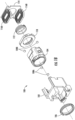
- embodiments of the present disclosure provided herein include optical assemblies, variable focus lens assemblies and variable focus imaging apparatuses including one or more such assemblies.
- Other implementations for one or more of the variable focus lens assemblies and/or variable focus imaging apparatuses will be, or will become, apparent to one with skill in the art upon examination of the following figures and detailed description. It is intended that all such additional implementations be included within this description be within the scope of the disclosure and be protected by the following claims.
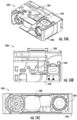
- an optical assembly comprising a housing, an optical member, a first pair of bearing balls, and a second pair of bearing balls.
- the optical member is configured to move within the housing and has two front tubular slots and two rear tubular slots.
- Each ball bearing of the first pair of bearing balls is housed in a respective one of the two front tubular slots and is configured to movably support the optical member within the housing at a first side of the optical member.
- Each ball bearing of the second pair of bearing balls is housed in a respective one of the two rear tubular slots and is configured to movably support the optical member within the housing at a second side of the optical member.
- the optical assembly further comprises a wired coil board configured to produce a magnetic flux upon energization.
- the optical member further comprises at least one permanent magnet on at least a portion of the optical member such that at all movement positions of the optical member, the at least one permanent magnet is in interactable proximity of the magnetic flux produced by the wired coil board.
- the wired coil board comprises a wired coil assembly configured to move at least a part of the optical member within a recessed portion defined by the wired coil board, based on a first current supplied to the wired coil assembly.
- the wired coil board comprises a wired coil assembly configured to move at least a part of the optical member out of a recessed portion defined by the wired coil board, based on a second current supplied to the wired coil assembly.
- a first end of the housing is towards a front side of the optical assembly that faces a scene to be imaged and a second end of the housing is towards a rear end of the optical assembly that faces an image sensor, and wherein the wired coil board is positioned towards the rear end of the optical assembly.
- the optical member further comprises a first permanent magnet and a second permanent magnet placed diagonally opposite to the first permanent magnet.
- the example variable focus lens further comprises a module base defining an inner module space designed to fit the lens barrel assembly, where the module base is designed to support the first positioning coil assembly at a first coil position and the second positioning coil assembly at a second coil position, the first coil position being opposite to the second coil position.
- the example variable focus lens further comprises at least one pair of bearing balls engaged with the module base and the lens barrel assembly, where the first positioning coil assembly, the second positioning coil assembly and the at least one pair of bearing balls, together with the lens barrel assembly, define a focus position for the lens barrel assembly.
- the module base and the lens barrel assembly each comprise a first bearing slot and a second bearing slot, each of the first bearing slots located opposite to one of the second bearing slots.
- the at least one pair of bearing balls comprises a first pair of bearing balls and a second pair of bearing balls. The first pair of bearing balls is engaged with the module base and the lens barrel assembly via each of the first bearing slots, and the second pair of bearing balls is engaged with the module base and the lens barrel assembly via each of the second bearing slots.
- Imaging apparatuses are configured to enable execution of one or more image capture and processing tasks.
- an image apparatus is configured to enable reading of symbols, such as one or more barcodes, QR codes, data matrices, and/or the like.
- imaging apparatuses include one or more imagers for capturing image data object(s) representing a particular field of view defined by the imager.
- an imager may include one or more image capture optics, such as one or more lens assemblies, coupled with an image sensor configured to capture light that traverses through the image capture optics to interact with the image sensor.
- the lens assembly may define a particular field of view to be captured by the associated image sensor, and/or may define a particular focus range such that the image sensor captures an image data object that is clear and/or otherwise optimal for processing at and/or around the focus range.
- imagers may be associated with an illuminator of and/or associated with the imaging apparatus, for example including an illumination projection lens and associated illumination source, that provides light that illuminates the field of view to be captured.
- Variable focus lens assemblies enable adjustment of the focus range to one or more different focus ranges.
- the effective range at which the lens assembly may be used to capture image data objects that are clear and/or well-defined enough to be successfully processed for a particular image processing task may be improved.
- a variable focus lens adjustable between a first focus range and a second focus range may be used to capture image data objects sufficient for processing without repositioning an object to be scanned and/or the imaging apparatus itself.
- conventional implementations for variable focusing remain bulky, slow, and/or vulnerable to one or more environmental impacts.
- conventional variable focus lenses are often not suitable for use in small form factor and mobile imaging apparatuses, and/or physically cannot fit within such apparatuses for use.
- Embodiments herein provide variable focus lens assemblies.
- Embodiments include variable focus lens assemblies including a lens barrel assembly positioned based on interactions between one or more positioning magnets and one or more positioning pads.
- each of a pair of positioning magnets is associated with one of a pair of positioning pads.
- the positioning pads are each associated with a positioning coil configured to receive an electrical charge that powers the positioning coil.
- the powered positioning coil is configured to generate a magnet force exerted to reposition the lens barrel assembly to a new focus position.
- the lens barrel assembly is positioned based on the powered state of each of the positioning coils.
- variable focus lens assemblies provide a sufficient reliability, compact size, low power consumption, and high-speed response sufficient for use in small form factor imaging apparatuses.
- variable focus lens assemblies may be implemented in one or more imaging apparatuses to improve the effective range over which the imaging apparatus may capture image data objects for successful processing.
- imaging apparatuses may be similarly implemented in one or more non-mobile imaging apparatuses.
- the embodiments may not be limited by a small form factor, but may use a similar structure as described herein.
- powering refers to providing a current to an electrical circuit, component, and/or electrical conductor.
- positioning coil assembly refers to a positioning coil connected to at least a flex component to connect the positioning coil to a module base and/or coil powering circuitry.
- coil powering circuitry refers to hardware configured to provide current to one or more positioning coil assemblies.
- coil powering circuitry includes at least one power source connected to one or a plurality of positioning coil assemblies.
- positioning magnet refers to a magnet included in a lens barrel assembly to enable shifting of a focus position for the lens barrel assembly.
- a lens barrel assembly includes a pair of positioning magnets designed to interact with one or more associated components, such as a pair of positioning coil assemblies and/or positioning pads, to change the focus position of the barrel lens assembly as described herein.
- Non-limiting examples of a positioning magnet includes a plated neodymium magnet, including without limitation a zinc-plated magnet, a nickel-plated magnet, and/or other protective coating.
- positioning pad refers to magnetic material designed to fit within the coil inner region of a positioning coil.
- a positioning pad is shaped as a cuboid.
- a positioning coil assembly is positioned adjacent to a positioning magnet that is associated with the positioning pad.
- a pair of symmetrical positioning pads are positioned opposite one another, each associated with one of a pair of positioning coil assemblies, the pair of positioning coil assemblies positioned opposite one another, such that when the positioning coil assemblies are in an non-powered state, the positioning pad is aligned with the positioning magnet.
- iron positioning pad refers to a positioning pad specifically formed of iron, including an iron coating, and/or formed of majority iron.
- module base refers to a housing configured to enable positioning and/or alignment of one or more components of a variable focus lens assembly. Additionally or alternatively, in some embodiments, a module base enables connection of one or more of the components with corresponding powering circuitry and/or processing circuitry.
- coil position refers to a position of a positioning coil with respect to an associated lens barrel assembly.
- a first positioning coil is positioned at a first coil position located on top of an associated lens barrel assembly
- a second positioning coil is positioned at a second coil location located on the bottom of an associated lens barrel assembly, such that the first coil position is opposite the second coil position.
- a positioning area refers to defined portion of a module base designed to support a positioning coil assembly, including a positioning pad within the coil inner region.
- a module base includes a first coil position and a second coil position to support a pair of positioning coil assemblies, the first coil position opposite the second coil position such that the pair of coil assemblies generates a magnetic force to move the lens barrel assembly along a longitudinal axis.
- inner module space refers to a void of space defined by the inner walls and/or other supporting structures of the module base.
- the inner module space is defined sufficiently to fit a lens barrel assembly and/or corresponding positioning and/or alignment components.
- bearing slot refers to a space in a component, defined by an outer boundary, designed to receive and/or movably secure a ball bearing.
- bearing slot opening defines a spherical, tubular, or cylindrical space configured to receive a ball bearing.
- ball bearing refers to a metallic, semi-metallic, or non-metallic solid ball and/or other circular roller designed to engage a bearing slot opening of a component.
- the ball bearing is designed to engage the bearing slot opening through sliding into the bearing slot opening.
- focus position refers to a position of a lens barrel assembly within the inner module space of a module base.
- the focus positioning of a lens barrel assembly represents a shift from a default position, and/or an absolute position, along a longitudinal axis.
- the focus position of lens barrel assembly is changed based on a value of power applied to one or more positioning coil assemblies.
- front positional limit refers to a focus position closest to the inner wall of the front of a module base.
- the front positional limit is defined by the inner wall of the front of the module base itself. In other embodiments, the front positional limit is defined by one or more front limit components.
- near focus position refers to a value of a focus position to focus the lens barrel assembly for a predetermined focus range under a predetermined threshold.
- far focus position refers to a value for a focus position to focus the lens barrel assembly for a second predetermined focus range above a predetermined threshold.
- neutral focus position refers to a value for a focus position to focus the lens barrel assembly for a third predetermined focus range at a predetermined threshold.
- visual encoded indicia refers to a rendered, printed, and/or otherwise visible representation of one or more symbologies configured for scanning by an imaging apparatus.
- Non-limiting examples of a visual encoded indicia include a 2D barcode, UPC, Quick Response Code, Data Matrix, and custom encoded image.
- the non-glossy dark surface of one or more of the positioning magnets may be obtained in any of a number of ways.
- one or more of the first positioning magnet 420A and/or second positioning magnet 420B include a magnet surface epoxy.
- the magnet surface epoxy may be applied to the positioning magnet(s) to cause such positioning magnet(s) to have a non-glossy dark surface without noticeably increasing the dimensions of the positioning magnet(s) and/or affecting the functionality of such positioning magnet(s).
- the open frame lens barrel 124 includes one or more openings to enable access to one or more limit screws.
- the open frame lens barrel 124 may include one or more additional openings located in the opposite corners of one or more bearing slots, for example bearing slots 408B.
- the additional openings may be sufficiently sized to enable one or more instruments to pass through the openings to engage one or more limit screws for adjustment.
- Example instruments include a screwdriver, hex key, and/or the like, for engaging one or more limit screws, and/or other positioning limit components.
- the additional openings enable access to back limiting screws, and/or other back positioning limit components, from the front of the lens barrel assembly.
- each of the positioning coils 604 defines a coil inner region comprising an open space between the wire coil.
- the positioning coil board 157 may include a positioning pad located in the coil inner region for each of the positioning coils 604.
- the first positioning pad 606A is located in a first coil inner region of the first positioning coil 604A.
- the second positioning pad 606B is located in a coil inner region of the second positioning coil 604B.
- each of the first positioning pad 606A and the second positioning pad 606B may comprise particular volumetric dimensions specific to fit within the inner region defined by the corresponding positioning coil.
- each of the positioning pads 606 is secured within the coil inner region using any of a myriad of manners.
- one or more for the positioning pads 606 is secured using one or more adhesives.
- each inner coil region is defined by a coil frame.
- each coil frame may be molded entirely and/or partially around the corresponding positioning pad of the positioning pads 606 to secure the corresponding positioning pad.
- the coiled wire is wound around the coil frame.
- the first positioning coil 604A may be powered to a first powered state to generate a first magnetic field
- the second positioning coil 604B may be powered to generate a second magnetic field symmetric to that of the first magnetic field. Accordingly, the first magnetic field and second magnetic field may cancel out with respect to one or more directions opposite one another.
- the interaction of the first magnetic field and second magnetic field may result in a resulting magnetic field providing a force in only one direction, for example representing a lateral direction of a lens barrel assembly.
- This resulting magnetic force may further interact with the default magnetic force between the positioning magnet(s) of a lens barrel assembly and the positioning pads 606A to move the lens barrel assembly to a new focus position, as described herein, based on the resulting magnetic force.
- the light trace 704 may be changed based on one or more changes to aspect(s) of the variable focus lens assembly 100.
- the focus position of the lens barrel assembly within the variable focus lens assembly 100 alters the manipulation of light by the variable focus lens assembly 100, such that incoming light at a particular point may interact with the image sensor 702 at different point(s) based on the focus position of the lens barrel assembly. Accordingly, by repositioning the lens barrel assembly within the variable focus lens assembly 100, the image data object captured by the image sensor 702 may change to reflect the adjusted focus position.
- the lens barrel assembly 104 in the inner module space is positioned such that the positioning magnets of the lens barrel assembly 104 align with the various axes associated with the pair of positioning pads.
- the front of the positioning magnets 420A and 420B is aligned with the pad front axis 802A
- the back of the positioning magnets 420A and 420B is aligned with the pad back axis 802C
- the center of the positioning magnets 420A and 420B is aligned with the pad center axis 802B.
- the front of the lens barrel assembly 104 is spaced by a first offset from the inner wall of the front of the module base 102.
- the inner wall of the front of the module base 102 is spaced from the front of the variable focus lens assembly 100 by the neutral focus frontal position offset.
- the neutral focus frontal position offset may be designed as a predetermined distance between the front of the lens barrel assembly 104 and the inner wall of the front of the module base 102 when the lens barrel assembly 104 is at a neutral focus position.
- the neutral focus frontal position offset represents a maximum distance that the lens barrel assembly 104 may be moved forward from the neutral focus position for example to focus the variable focus lens assembly 100 for improved near field focusing.
- the back of the lens barrel assembly 104 is positioned as far backwards as possible within the module base 102.
- the inner wall of the back of the module base 102 may be in contact with the back of the lens barrel assembly 104 to stop the lens barrel assembly 104 from moving any further backwards.
- the lens barrel assembly 104 may be in contact with one or more back limit components, such as back limit screws. It should be appreciated that, as illustrated, the far focus position may be positioned backwards from the neutral focus position by the distance represented by the neutral focus back position offset.
- the lens barrel assembly 104 is positioned such that the positioning magnets of the lens barrel assembly 104 are offset from the various axes associated with the pair of positioning pads by a near position magnetic offset.
- the front of the positioning magnets is shifted forward from the pad front axis 802A by the near position magnetic offset
- the back of the positioning magnets is shifted forward from the pad back axis 802C by the near position magnetic offset
- the center of the positioning magnets is shifted forward from the pad center axis 802B by the near position magnetic offset.
- the positioning magnets are larger and/or smaller than the positioning pads, only the center of the positioning magnets is offset from the pad center axis 802B by the near position magnetic offset.
- the near focus position may be defined by the position of the lens barrel assembly 104 when one or more coil positioning assemblies of the variable focus lens assembly 100 are in a second powered state, for example a near focus powered state.
- the lens barrel assembly 104 may be positioned within the variable focus lens assembly 100 based on the magnetic force created by the coil positioning assemblies in the near focus powered state together with the default magnetic force between one or more positioning magnets of the lens barrel assembly 104 and one or more positioning pads of the variable focus lens assembly 100.
- the interaction between the magnetic forces may result in a resulting magnetic force defining the near focus position.
- the back of the lens assembly 104 is spaced by a second offset from the inner wall of the back of the module base 102.
- the inner wall of the back of the module base 102 is spaced from the back of the lens barrel assembly 104 by the near focus back position offset.
- the near focus back position offset may represent a distance equal to the neutral focus back position offset added to the neutral focus frontal position offset.
- the near focus back position offset represents the maximum distance the back of the lens barrel assembly 104 can be located from the inner wall of the module base 102.
- the magnetic offset may match the neutral focus frontal position offset as described above. It should be appreciated that moving the lens barrel assembly 104 may improve the near field focusing of the variable focus lens assembly 100.
- the lens barrel assembly may be positioned continuously within the module base.
- the positioning coil assemblies of the variable focus lens assembly 100 may be powered to any number of powered states. Each of the powered states may correspond to a resulting magnetic force defining a different focus position.
- the near field focusing of the variable focus lens assembly 100 improves.
- the far field focusing of the variable focus lens assembly 100 improves.
- FIGS. 9A, 9B, and 9C each illustrate a visualization of an image data object including representations of various visual encoded indicia captured by an image sensor using a variable focus lens assembly having a lens barrel assembly at different focus positions. Specifically, each of FIG. 9A, 9B, and 9C depict a near-field indicia at a first distance the variable focus lens assembly, a neutral-field indicia at a second distance from the variable focus lens assembly, and a far-field indicia at a third distance from the variable focus lens assembly.
- the near-field indicia may be positioned 1 meter from the variable focus lens assembly
- the neutral-field indicia may be positioned 1.8 meters from the variable focus lens assembly
- the far-field indicia may be positioned 6 meters from the variable focus lens assembly. It should be appreciated that, in other embodiments, the near-field indicia, neutral field indicia, and/or far-field indicia may be positioned at alternative distances to those described above, for example where the far-field indicia is positioned further than the neutral-field indicia positioned further than the near-field indicia.
- FIG. 9A depicts an image data object representing the various visual encoded indicia as captured using a lens barrel assembly at a default focus position, for example as depicted with respect to FIG. 8A .
- the lens barrel assembly may be positioned to enable capture of the visual encoded indicia at medium or determined middle-range, distances in better focus, for example at and/or around 1.8 meter from the lens barrel assembly.
- FIG. 9A includes a first representation of the far-field indicia 902A, a first representation of the neutral-field indicia 904A, and a first representation of the near-field indicia 906A.
- the first representation of the far-field indicia 902A is not in focus, such that the captured representation is blurry due to not being at a distance close to the focus range associated with the neutral focus position of the lens barrel assembly.
- the first representation of the near-field indicia 906A is also not in focus, such that the captured representation is blurry as also not being at a distance close to the focus range associated with the neutral focus position of the lens barrel assembly.
- the near-field indicia 906A is closer to the focus range associated with the near focus position for the lens barrel assembly, and as such in better focus than the representation of the far-field indicia 902A.
- the first representation of the neutral-field indicia 904A is best in focus as the focus range for the neutral focus position matches, and/or is closest to, the distance at which the neutral-field indicia is located. As such, objects at this distance are represented most clearly in captured image data objects.
- the second representation of the far-field indicia 902B is least in focus, such that the captured representation is blurry for being the furthest from the focus range corresponding to the near focus position of the lens barrel assembly.
- the second representation of the neutral-field indicia 904B is more in focus than the far-field indicia 902B, however the neutral-field indicia 904B remains partially blurred as the focus range for the neutral focus position is not equal to the distance at which the neutral-field indicia is located.
- the second representation of the near-field indicia 906B is the most in focus, for example such that the data represented in the image data object most clearly represents the visual encoded indicia.
- FIG. 9C depicts an image data object representing the various visual encoded indicia as captured using a lens barrel assembly at a far focus position.
- the lens barrel assembly may be positioned to enable capture of the visual encoded indicia at far distances in better focus, for example at and/or around, or more than, 6 meters from the lens barrel assembly.
- FIG. 9C includes a third representation of the far-field indicia 902C, a third representation of the neutral-field indicia 904C, and a third representation of the near-field indicia 906C.
- the third representation of the far-field indicia 902C is the most in focus, for example such that the data represented in the image data object most clearly represents the visual encoded indicia.
- the focus range for the far focus position may match, or most closely match, the distance for the far-field indicia, such that objects at this distance are represented most clearly in captured image data objects.
- visual encoded indicia at the far focus range associated with the far focus position for the lens barrel assembly for example 6 meter, may be most likely to be successfully detected and/or successfully decoded from the image data object.
- representations are merely exemplary. In other embodiments, such representations may become better in focus by positioning the lens barrel assembly at one or more other focus positions.
- a representation of a visual encoded indicia at 3 meters may be in focus at an additional focus position between the neutral focus position and the far focus position along a continuous focus position spectrum.
- FIGS. 10A and 10B illustrate the magnetic forces exerted by each of a pair of coil positioning assemblies associated with a pair of positioning magnets of a variable focus lens assembly, in accordance with at least some example embodiments of the present disclosure.
- FIG. 10A depicts the magnetic forces exerted by each of a pair of coil positioning assemblies associated with a pair of positioning magnets of a variable focus lens assembly in a circumstance where the pair of coil positioning assemblies are in a non-powered state.
- FIG. 10B depicts the magnetic forces exerted by each of a pair of coil positioning assemblies associated with a pair of positioning magnets of a variable focus lens assembly in a circumstance where the pair of coil positioning assemblies are in a first powered state.
- a first positioning magnet in combination with a first positioning coil assembly exerts a first magnet-coil force 1002.
- the first positioning magnet and first positioning coil assembly may be located towards the top of the variable focus lens assembly.
- a second positioning magnet in combination with a second positioning coil assembly exerts a second magnet-coil force 1004.
- the second positioning magnet and second positioning coil assembly may be located towards the top of the variable focus lens assembly.
- the first magnet-coil force 1002 may be symmetric with respect to the second magnet-coil force 1004.
- the magnetic forces 1002 and 1004 may be generated opposite one another, such that the first magnet-coil force 1002 combines with the second magnet-coil force 1004 along a desired direction of movement (e.g., forward or backwards) to improve the efficiency for moving the lens barrel assembly in the desired direction, and counteracts in one or more orthogonal directions not required for such movement (for example, towards one or more positioning pads).
- the lens barrel assembly may remain at a default focus position despite the presence of the first magnet-coil force 1002 and second magnet-coil force 1004.
- the third magnet-coil force 1052 and the fourth magnet-coil force 1054 each exert magnetic forces in the same direction parallel to the direction of movement enabled by engagement of the lens barrel assembly with one or more bearing balls (for example, towards the front of the module base). These magnetic forces may be applied to the lens barrel assembly to reposition the lens barrel assembly to a new focus position. It should be appreciated that in a circumstance where the positioning coil assemblies are powered to a different powered state, for example to a negative state as compared to the first powered state, the generated magnetic forces may be in the opposite direction parallel to the optical axis, for example such that the magnetic forces are applied to the lens barrel assembly to cause movement in the other direction (for example, towards the back of the module base).
- FIG. 11 illustrates an example distribution of the force in relation to displacement.
- the distribution includes a graph 1150 of the displacement of the lens barrel assembly as compared to the exerted magnetic force.
- the front of the module base may be associated with a positive displacement
- the back of the module base may be associated with a negative displacement.
- the magnetic force is approximately 22 mN.
- the required force decreases and approaches zero.
- the required force further increases, approaching 39 mN.
- the focus position may be defined based on the current direction and strength within one or more positioning coil assemblies, such as a pair of positioning coil assemblies.
- the lens barrel assembly may be positioned at a default position under no current to the pair of positioning coil assemblies (e.g., in a non-powered state).
- the lens barrel assembly may be positioned at a maximal forward position when a first maximal current strength in a first direction is applied to the pair of positioning coil assemblies (e.g., a first powered state).
- the lens barrel assembly may be positioned at a maximal backward position when a second maximal current strength in a second direction is applied to the pair of positioning coil assemblies (e.g., a second powered state).
- variable focus lens assembly By distributing the various required forces to position the lens barrel assembly at the front, back, or neutral focus position within the module base, the variable focus lens assembly is designed to quickly position the lens barrel assembly to the extreme positions by rapidly altering the exerted magnetic force.
- one or more positioning coil assemblies may be manipulated to exert zero or near-zero magnetic force, such as the lowest possible magnetic force, to position the lens barrel assembly at a near focus position as close to the front of the module base as possible, and for example furthest from an image sensor.
- one or more positioning coil assemblies may be manipulated to exert a maximum magnetic force, or near-maximum magnetic force, to position the lens barrel assembly at a far focus position as close to the back of the module base as possible, and for example closest to a corresponding image sensor. Further, one or more positioning coil assemblies may be manipulated to exert an intermediate, target magnetic force to position the lens barrel assembly at a neutral focus position towards the middle of the module base.
- the variable focus lens assembly may be designed to quickly exert the necessary force to enable displacement of the lens barrel assembly to translate to at least these three discrete focus positions. It should be appreciated that, in other embodiments, a variable focus lens assembly may be configured to exert the necessary force to enable displacement of the lens barrel assembly to translate to any number of other focus positions.
- variable focus lens assemblies integrating at least one variable focus lens assembly.
- one or more of the of the apparatuses as described may include one variable focus lens assembly, for example to replace far-field imaging optics.
- one or more of the apparatuses may include a plurality of variable focus lens assemblies, for example at least a first to replace far-field imaging optics and a second to replace near-field imaging optics.
- the specific embodiments described and/or depicted herein should not limit the scope and spirit of the disclosure.
- FIGS. 12 and 13 illustrate an example variable focus multi-sensor imaging engine including a variable focus lens assembly.
- FIG. 12 depicts a front perspective view 1200 of a variable focus multi-sensor imaging engine.
- FIG. 13 depicts a back perspective view 1300 of the variable focus multi-sensor imaging engine.
- the near-field lens assembly and near-field image sensor may form a near-field imager configured to receive light from a particular near-field of view and capture said light in a near-field image data object that represents the near-field of view from the perspective of the near-field imager.
- the variable focus multi sensor imaging engine further includes integrated illumination-aimer optics (1208, 1308).
- the integrated illumination-aimer optics may be designed to produce one or more illumination patterns based on incoming light received from one or more illuminator sources (not depicted) of the variable focus multi-sensor imaging engine.
- the integrated illumination-aimer optics may be associated with illumination optics located underneath the integrated illumination-aimer optics.
- the integrated illumination-aimer optics is configured to receive an aimer illumination and project a corresponding aimer pattern based on one or more aimer subassemblies of the integrated illumination-aimer optics.
- the variable focus multi-sensor imaging engine further includes an imaging board 1310.
- the imaging board (1210, 1310) that includes hardware, circuitry, and/or the like, configured to power and/or enable activation of one or more associated components connected with the imaging board.
- the imaging board is connected to at least the near-field image sensor (1204, 1304), image sensor (1206), one or more illuminator sources of the variable focus multi-sensor imaging engine, and/or one or more aimer sources of the variable focus multi-sensor imaging engine.
- the imaging board (1210, 1310) may enable activation of each of these components, for example to activate the near-field image sensor 1304 and/or 1306 to cause capture of an image data object.
- the imaging board further transmits such captured image data objects from the image sensor(s) 1306 and/or 1304 to one or more processors and/or other hardware connected to the variable focus multi-sensor imaging engine.
- the imaging board is connected to at least the variable focus lens assembly 100, for example to provide power to and/or otherwise activate one or more coil positioning subassemblies to a desired powered state.
- the imaging board is connected with one or more external processors and/or other circuitry for performing such functionality.
- the imaging board is embodied by one or more printed circuit board(s).
- the imaging board includes a flexible printed circuit board configured to connect various layers on which one or more other components of the variable focus multi-sensor imaging engine may be mounted and/or otherwise connected.
- variable focus lens assembly 100 may provide variable focusing to the variable focus multi-sensor imaging engine within a range of focus positions based on the design of the variable focus lens assembly 100.
- the variable focus lens assembly 100 is configured for positioning at a near focus position, a neutral focus position, and a far focus position.
- the variable focus lens assembly 100 may include one or more activation signals to power one or more coil positioning assemblies as determined appropriate to reposition a lens barrel assembly within the variable focus lens assembly 100 to a desired focus position for capturing one or more image data objects.
- variable focus multi-sensor imaging engine may be included in one or more imaging apparatuses.
- FIGS. 14A, 14B, and 14C illustrate an example variable focus multi-sensor imaging apparatus 1400, in accordance with at least some example embodiments of the present disclosure.
- FIG. 14A depicts the variable focus multi-sensor imaging apparatus 1400 from a front perspective view.
- FIG. 14B depicts the variable focus multi-sensor imaging apparatus 1400 from a top-down orthogonal view.
- FIG. 14C depicts the variable focus multi-sensor imaging apparatus 1400 from a front orthogonal view.
- the variable focus multi-sensor imaging apparatus 1400 includes the variable focus multi-sensor imaging engine 1200 housed within a particular apparatus chassis 1402.
- the apparatus chassis 1402 may be configured to fit each of the components described with respect to the variable focus multi-sensor imaging engine 1200.
- the apparatus chassis 1402 may be designed and/or modified to define a variable focus lens assembly space 1404, such as is illustrated in FIG. 15 .
- the variable focus lens assembly space 1404 may be configured to fit the variable focus lens barrel assembly, for example variable focus lens barrel assembly 100, within the defined variable focus lens assembly space 1404.
- the apparatus chassis 1402 comprises an existing apparatus chassis locally modified to define the variable focus lens assembly space 1404.
- variable focus lens assembly space 1404 includes one or more hardware support structures, protrusions, and/or the like configured to engage the variable focus lens assembly within the variable focus lens assembly space 1404 and/or otherwise enable connection between the variable focus lens assembly and one or more components of the variable focus multi-sensor imaging engine 1200, 1300, such as an imaging board.
- FIG. 17 illustrates a flowchart depicting example operations of an example process 1900 for assembling a variable focus lens assembly, in accordance with at least some example embodiments of the present disclosure.
- a machine operator performs some or all of the depicted operations.
- Block 1702 includes assembling a lens barrel, a pair of positioning magnets, and an imaging lens to form a lens barrel assembly.
- the lens barrel assembly comprises a first positioning magnet of the pair of positioning magnets mounted opposite a second positioning magnet of the pair of positioning magnets.
- each positioning magnet is mounted using one or more adhesive and/or chemical securing means.
- each positioning magnet is physically secured by engaging with the lens barrel.
- the lens barrel assembly also includes a plurality of bearing slots carved into a surface of the housing of the lens barrel assembly.
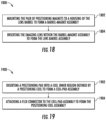
- the process for assembling the lens barrel, the pair of positioning magnets, and the imaging lens to form the lens barrel assembly includes one or more subprocesses, for example process 1800 as described below with respect to FIG. 18 .
- Block 1708 includes engaging at least two pairs of the bearing balls with the lens barrel assembly through the bearing slots of the module base.
- each of the bearing balls engages a corresponding bearing slot each of the lens barrel assembly and the module base.
- the lens barrel assembly may be engaged such that the lens barrel assembly may slide along a depth of the bearing slots in the lens barrel assembly when force is applied to the lens barrel assembly, to reposition within the module base.
- Block 1710 includes assembling a first positioning coil assembly and a second positioning coil assembly.
- each positioning coil assembly may include at least a positioning coil and a corresponding positioning pad.
- the positioning coil assembly may be assembled for attaching to one or more other components as described.
- the process for assembling the first positioning coil assembly and/or the second positioning coil assembly includes one or more subprocesses, for example process 1900 as described below with respect to FIG. 19 .
- Block 1712 includes attaching, on the module base, the first positioning coil assembly and the second positioning coil assembly.
- the first positioning coil assembly may be positioned opposite the second positioning coil assembly, for example such that the first positioning coil assembly is located at a coil location on a top surface of the module base and the second positioning coil is located at a second coil location opposite the first coil location on a bottom surface of the module base.
- the first positioning coil assembly and/or second positioning coil assembly are attached on the module base through attaching the first positioning coil assembly and/or the second positioning coil assembly to a positioning coil board and attaching the positioning coil board to the module base.
- Block 1902 begins after one or more blocks as depicted and/or described with respect to the other flowcharts herein, for example after block 1708 as depicted with respect to FIG. 17 .
- Block 1902 includes inserting a positioning pad into a coil inner region defined by a positioning coil to form a coil-pad assembly.
- a positioning coil embodies one or more wound wires, such that the wound wires surround the coil inner region.
- a positioning pad may be of a sufficient size to fit within the coil inner region defined by the positioning coil.
- the positioning pad is secured within the coil inner region by any of a number of known physical and/or chemical means.
- flow Upon completion of block 1904, in some embodiments, flow returns to one or more other blocks of the flows as described and/or illustrated. For example, in some embodiments, flow returns to block 1710 to continue the process described above with respect to FIG. 17 .
Landscapes
- Physics & Mathematics (AREA)
- General Physics & Mathematics (AREA)
- Optics & Photonics (AREA)
- Engineering & Computer Science (AREA)
- Chemical & Material Sciences (AREA)
- Combustion & Propulsion (AREA)
- Electromagnetism (AREA)
- Power Engineering (AREA)
- Lens Barrels (AREA)
- Cameras In General (AREA)
- Studio Devices (AREA)
Applications Claiming Priority (2)
| Application Number | Priority Date | Filing Date | Title |
|---|---|---|---|
| US17/157,986 US11886036B2 (en) | 2021-01-25 | 2021-01-25 | Variable focus assemblies and apparatuses having crossed bearing balls |
| EP22152327.7A EP4057043B1 (de) | 2021-01-25 | 2022-01-19 | Anordnungen mit variablem fokus und vorrichtungen mit gekreuzten lagerkugeln |
Related Parent Applications (1)
| Application Number | Title | Priority Date | Filing Date |
|---|---|---|---|
| EP22152327.7A Division EP4057043B1 (de) | 2021-01-25 | 2022-01-19 | Anordnungen mit variablem fokus und vorrichtungen mit gekreuzten lagerkugeln |
Publications (2)
| Publication Number | Publication Date |
|---|---|
| EP4398463A2 true EP4398463A2 (de) | 2024-07-10 |
| EP4398463A3 EP4398463A3 (de) | 2025-11-26 |
Family
ID=79730380
Family Applications (2)
| Application Number | Title | Priority Date | Filing Date |
|---|---|---|---|
| EP22152327.7A Active EP4057043B1 (de) | 2021-01-25 | 2022-01-19 | Anordnungen mit variablem fokus und vorrichtungen mit gekreuzten lagerkugeln |
| EP24176898.5A Pending EP4398463A3 (de) | 2021-01-25 | 2022-01-19 | Anordnungen mit variablem fokus und vorrichtungen mit gekreuzten lagerkugeln |
Family Applications Before (1)
| Application Number | Title | Priority Date | Filing Date |
|---|---|---|---|
| EP22152327.7A Active EP4057043B1 (de) | 2021-01-25 | 2022-01-19 | Anordnungen mit variablem fokus und vorrichtungen mit gekreuzten lagerkugeln |
Country Status (4)
| Country | Link |
|---|---|
| US (2) | US11886036B2 (de) |
| EP (2) | EP4057043B1 (de) |
| JP (2) | JP7305816B2 (de) |
| CN (1) | CN114895429B (de) |
Families Citing this family (2)
| Publication number | Priority date | Publication date | Assignee | Title |
|---|---|---|---|---|
| US20230070594A1 (en) * | 2021-09-03 | 2023-03-09 | Hand Held Products, Inc. | Lens unit of an imaging assembly |
| US12197034B2 (en) * | 2023-02-28 | 2025-01-14 | Hand Held Products, Inc. | Bi-directional closed loop multi-focus-position lens apparatus and method |
Family Cites Families (24)
| Publication number | Priority date | Publication date | Assignee | Title |
|---|---|---|---|---|
| US20070035628A1 (en) | 2005-08-12 | 2007-02-15 | Kunihiko Kanai | Image-capturing device having multiple optical systems |
| JP4792300B2 (ja) | 2005-08-12 | 2011-10-12 | イーストマン コダック カンパニー | 複数光学系を有する撮像装置 |
| TWI302629B (en) | 2005-08-25 | 2008-11-01 | Powergate Optical Inc | A vcm auto-focusing device having position feedback and an auto-focusing method |
| CN101295062B (zh) | 2007-04-29 | 2010-09-29 | 鸿富锦精密工业(深圳)有限公司 | 镜头模组及相机模组 |
| JP2010068635A (ja) | 2008-09-11 | 2010-03-25 | Sharp Corp | アクチュエータ、該アクチュエータを備える撮像機器および電子機器 |
| JP5627991B2 (ja) | 2010-10-27 | 2014-11-19 | シャープ株式会社 | カメラモジュール |
| US20120237147A1 (en) | 2011-03-18 | 2012-09-20 | Digital Imaging Systems Gmbh | Integrated ball cage |
| US9134503B2 (en) | 2012-07-06 | 2015-09-15 | Apple Inc. | VCM OIS actuator module |
| US9578242B2 (en) | 2014-04-11 | 2017-02-21 | Samsung Electro-Mechanics Co., Ltd. | Camera module |
| US9955077B2 (en) | 2014-06-20 | 2018-04-24 | Samsung Electro-Mechanics Co., Ltd. | Camera module |
| KR101825731B1 (ko) | 2014-12-04 | 2018-03-23 | 에이에이씨 어쿠스틱 테크놀로지스(심천)컴퍼니 리미티드 | 광학 손떨림 보정 가능한 카메라 렌즈 모듈 |
| JP3200481U (ja) | 2015-02-26 | 2015-10-22 | 株式会社Est | レンズ駆動装置 |
| JP2018120072A (ja) | 2017-01-25 | 2018-08-02 | シーエム・テクノロジー株式会社 | レンズ駆動装置 |
| KR102072811B1 (ko) | 2017-06-16 | 2020-03-02 | 삼성전기주식회사 | 카메라 모듈 |
| JP2019113638A (ja) * | 2017-12-22 | 2019-07-11 | シーエム・テクノロジー株式会社 | レンズ駆動装置 |
| KR102566880B1 (ko) | 2018-07-12 | 2023-08-16 | 마이크로엑츄에이터(주) | 자동 초점 조절장치 |
| KR102723559B1 (ko) | 2018-08-02 | 2024-10-30 | 엘지이노텍 주식회사 | 렌즈 구동장치 및 이를 포함하는 카메라 모듈 |
| KR102585027B1 (ko) * | 2018-08-16 | 2023-10-06 | 엘지이노텍 주식회사 | 렌즈 구동장치 및 이를 포함하는 카메라 모듈 |
| CN113167986B (zh) | 2019-02-25 | 2023-09-01 | 核心光电有限公司 | 多光圈相机,具有至少一个两种状态变焦的相机 |
| TWI724412B (zh) | 2019-04-24 | 2021-04-11 | 大陽科技股份有限公司 | 鏡頭驅動模組與電子裝置 |
| CN110908067B (zh) | 2019-07-22 | 2024-10-25 | 睿恩光电有限责任公司 | 透镜驱动装置、相机装置及电子设备 |
| CN210488101U (zh) * | 2019-07-22 | 2020-05-08 | 睿恩光电有限责任公司 | 透镜驱动装置、相机装置及电子设备 |
| US11428894B2 (en) | 2020-02-04 | 2022-08-30 | Hand Held Products, Inc. | Discrete variable focus assemblies and apparatuses |
| CN111580324B (zh) | 2020-06-08 | 2022-02-22 | 昆山联滔电子有限公司 | 一种音圈马达 |
-
2021
- 2021-01-25 US US17/157,986 patent/US11886036B2/en active Active
-
2022
- 2022-01-18 JP JP2022005668A patent/JP7305816B2/ja active Active
- 2022-01-19 EP EP22152327.7A patent/EP4057043B1/de active Active
- 2022-01-19 EP EP24176898.5A patent/EP4398463A3/de active Pending
- 2022-01-25 CN CN202210090173.1A patent/CN114895429B/zh active Active
-
2023
- 2023-06-28 JP JP2023106066A patent/JP7680498B2/ja active Active
- 2023-12-19 US US18/544,993 patent/US20240118515A1/en active Pending
Also Published As
| Publication number | Publication date |
|---|---|
| US20220236514A1 (en) | 2022-07-28 |
| EP4057043C0 (de) | 2024-06-05 |
| US20240118515A1 (en) | 2024-04-11 |
| JP2023123730A (ja) | 2023-09-05 |
| CN114895429B (zh) | 2025-03-18 |
| EP4398463A3 (de) | 2025-11-26 |
| JP2022113656A (ja) | 2022-08-04 |
| EP4057043A2 (de) | 2022-09-14 |
| CN114895429A (zh) | 2022-08-12 |
| US11886036B2 (en) | 2024-01-30 |
| EP4057043B1 (de) | 2024-06-05 |
| JP7680498B2 (ja) | 2025-05-20 |
| JP7305816B2 (ja) | 2023-07-10 |
| EP4057043A3 (de) | 2023-01-18 |
Similar Documents
| Publication | Publication Date | Title |
|---|---|---|
| US12411304B2 (en) | Discrete variable focus assemblies, apparatuses, and methods of use | |
| US20240118515A1 (en) | Variable focus assemblies and apparatuses having crossed bearing balls | |
| US11262593B2 (en) | Reflecting module for optical image stabilization (OIS) and camera module including the same | |
| US10564442B2 (en) | Apparatus for driving optical-reflector for OIS with multi-axial structure | |
| CN110658663B (zh) | 光阑模块及包括该光阑模块的相机模块 | |
| CN209979982U (zh) | 光圈模块、相机模块及便携式电子装置 | |
| US12523919B2 (en) | Camera module | |
| KR20230101871A (ko) | 보이스 코일 모터, 카메라 모듈, 및 전자 디바이스 | |
| CN219496782U (zh) | 自动对焦马达及摄像模组 | |
| KR101729543B1 (ko) | 듀얼 렌즈용 싱글 액츄에이터 및 이를 포함하는 카메라 모듈 | |
| KR20250053010A (ko) | 렌즈 구동 장치, 카메라 모듈, 및 광학기기 | |
| EP4425232A1 (de) | Bidirektionale multifokuspositionslinsenvorrichtung mit geschlossenem regelkreis und verfahren |
Legal Events
| Date | Code | Title | Description |
|---|---|---|---|
| PUAI | Public reference made under article 153(3) epc to a published international application that has entered the european phase |
Free format text: ORIGINAL CODE: 0009012 |
|
| STAA | Information on the status of an ep patent application or granted ep patent |
Free format text: STATUS: THE APPLICATION HAS BEEN PUBLISHED |
|
| AC | Divisional application: reference to earlier application |
Ref document number: 4057043 Country of ref document: EP Kind code of ref document: P |
|
| AK | Designated contracting states |
Kind code of ref document: A2 Designated state(s): AL AT BE BG CH CY CZ DE DK EE ES FI FR GB GR HR HU IE IS IT LI LT LU LV MC MK MT NL NO PL PT RO RS SE SI SK SM TR |
|
| RAP3 | Party data changed (applicant data changed or rights of an application transferred) |
Owner name: HAND HELD PRODUCTS, INC. |
|
| REG | Reference to a national code |
Ref country code: DE Ref legal event code: R079 Free format text: PREVIOUS MAIN CLASS: H02K0041035000 Ipc: G02B0007020000 |
|
| PUAL | Search report despatched |
Free format text: ORIGINAL CODE: 0009013 |
|
| AK | Designated contracting states |
Kind code of ref document: A3 Designated state(s): AL AT BE BG CH CY CZ DE DK EE ES FI FR GB GR HR HU IE IS IT LI LT LU LV MC MK MT NL NO PL PT RO RS SE SI SK SM TR |
|
| RIC1 | Information provided on ipc code assigned before grant |
Ipc: G02B 7/02 20210101AFI20251020BHEP Ipc: G02B 7/08 20210101ALI20251020BHEP Ipc: G02B 27/00 20060101ALI20251020BHEP Ipc: H02K 41/02 20060101ALI20251020BHEP Ipc: G03B 3/10 20210101ALI20251020BHEP Ipc: H02K 41/035 20060101ALI20251020BHEP |