EP4398457A1 - Motor - Google Patents
Motor Download PDFInfo
- Publication number
- EP4398457A1 EP4398457A1 EP21955931.7A EP21955931A EP4398457A1 EP 4398457 A1 EP4398457 A1 EP 4398457A1 EP 21955931 A EP21955931 A EP 21955931A EP 4398457 A1 EP4398457 A1 EP 4398457A1
- Authority
- EP
- European Patent Office
- Prior art keywords
- magnet
- wall
- stator
- motor
- rotor
- Prior art date
- Legal status (The legal status is an assumption and is not a legal conclusion. Google has not performed a legal analysis and makes no representation as to the accuracy of the status listed.)
- Pending
Links
Images





Classifications
-
- H—ELECTRICITY
- H02—GENERATION; CONVERSION OR DISTRIBUTION OF ELECTRIC POWER
- H02K—DYNAMO-ELECTRIC MACHINES
- H02K1/00—Details of the magnetic circuit
- H02K1/06—Details of the magnetic circuit characterised by the shape, form or construction
- H02K1/22—Rotating parts of the magnetic circuit
- H02K1/27—Rotor cores with permanent magnets
- H02K1/2706—Inner rotors
- H02K1/272—Inner rotors the magnetisation axis of the magnets being perpendicular to the rotor axis
- H02K1/274—Inner rotors the magnetisation axis of the magnets being perpendicular to the rotor axis the rotor consisting of two or more circumferentially positioned magnets
- H02K1/2753—Inner rotors the magnetisation axis of the magnets being perpendicular to the rotor axis the rotor consisting of two or more circumferentially positioned magnets the rotor consisting of magnets or groups of magnets arranged with alternating polarity
- H02K1/278—Surface mounted magnets; Inset magnets
-
- H—ELECTRICITY
- H02—GENERATION; CONVERSION OR DISTRIBUTION OF ELECTRIC POWER
- H02K—DYNAMO-ELECTRIC MACHINES
- H02K21/00—Synchronous motors having permanent magnets; Synchronous generators having permanent magnets
- H02K21/12—Synchronous motors having permanent magnets; Synchronous generators having permanent magnets with stationary armatures and rotating magnets
- H02K21/14—Synchronous motors having permanent magnets; Synchronous generators having permanent magnets with stationary armatures and rotating magnets with magnets rotating within the armatures
- H02K21/16—Synchronous motors having permanent magnets; Synchronous generators having permanent magnets with stationary armatures and rotating magnets with magnets rotating within the armatures having annular armature cores with salient poles
-
- H—ELECTRICITY
- H02—GENERATION; CONVERSION OR DISTRIBUTION OF ELECTRIC POWER
- H02K—DYNAMO-ELECTRIC MACHINES
- H02K1/00—Details of the magnetic circuit
- H02K1/06—Details of the magnetic circuit characterised by the shape, form or construction
- H02K1/22—Rotating parts of the magnetic circuit
- H02K1/27—Rotor cores with permanent magnets
- H02K1/2706—Inner rotors
- H02K1/272—Inner rotors the magnetisation axis of the magnets being perpendicular to the rotor axis
- H02K1/274—Inner rotors the magnetisation axis of the magnets being perpendicular to the rotor axis the rotor consisting of two or more circumferentially positioned magnets
- H02K1/2753—Inner rotors the magnetisation axis of the magnets being perpendicular to the rotor axis the rotor consisting of two or more circumferentially positioned magnets the rotor consisting of magnets or groups of magnets arranged with alternating polarity
- H02K1/276—Magnets embedded in the magnetic core, e.g. interior permanent magnets [IPM]
-
- H—ELECTRICITY
- H02—GENERATION; CONVERSION OR DISTRIBUTION OF ELECTRIC POWER
- H02K—DYNAMO-ELECTRIC MACHINES
- H02K1/00—Details of the magnetic circuit
- H02K1/06—Details of the magnetic circuit characterised by the shape, form or construction
- H02K1/22—Rotating parts of the magnetic circuit
- H02K1/27—Rotor cores with permanent magnets
- H02K1/2706—Inner rotors
- H02K1/272—Inner rotors the magnetisation axis of the magnets being perpendicular to the rotor axis
- H02K1/274—Inner rotors the magnetisation axis of the magnets being perpendicular to the rotor axis the rotor consisting of two or more circumferentially positioned magnets
- H02K1/2753—Inner rotors the magnetisation axis of the magnets being perpendicular to the rotor axis the rotor consisting of two or more circumferentially positioned magnets the rotor consisting of magnets or groups of magnets arranged with alternating polarity
- H02K1/276—Magnets embedded in the magnetic core, e.g. interior permanent magnets [IPM]
- H02K1/2766—Magnets embedded in the magnetic core, e.g. interior permanent magnets [IPM] having a flux concentration effect
-
- H—ELECTRICITY
- H02—GENERATION; CONVERSION OR DISTRIBUTION OF ELECTRIC POWER
- H02K—DYNAMO-ELECTRIC MACHINES
- H02K1/00—Details of the magnetic circuit
- H02K1/06—Details of the magnetic circuit characterised by the shape, form or construction
- H02K1/22—Rotating parts of the magnetic circuit
- H02K1/27—Rotor cores with permanent magnets
- H02K1/2706—Inner rotors
- H02K1/272—Inner rotors the magnetisation axis of the magnets being perpendicular to the rotor axis
- H02K1/274—Inner rotors the magnetisation axis of the magnets being perpendicular to the rotor axis the rotor consisting of two or more circumferentially positioned magnets
- H02K1/2753—Inner rotors the magnetisation axis of the magnets being perpendicular to the rotor axis the rotor consisting of two or more circumferentially positioned magnets the rotor consisting of magnets or groups of magnets arranged with alternating polarity
- H02K1/278—Surface mounted magnets; Inset magnets
- H02K1/2783—Surface mounted magnets; Inset magnets with magnets arranged in Halbach arrays
-
- H—ELECTRICITY
- H02—GENERATION; CONVERSION OR DISTRIBUTION OF ELECTRIC POWER
- H02K—DYNAMO-ELECTRIC MACHINES
- H02K1/00—Details of the magnetic circuit
- H02K1/06—Details of the magnetic circuit characterised by the shape, form or construction
- H02K1/22—Rotating parts of the magnetic circuit
- H02K1/27—Rotor cores with permanent magnets
- H02K1/2786—Outer rotors
- H02K1/2787—Outer rotors the magnetisation axis of the magnets being perpendicular to the rotor axis
- H02K1/2789—Outer rotors the magnetisation axis of the magnets being perpendicular to the rotor axis the rotor consisting of two or more circumferentially positioned magnets
- H02K1/2791—Surface mounted magnets; Inset magnets
- H02K1/2792—Surface mounted magnets; Inset magnets with magnets arranged in Halbach arrays
-
- H—ELECTRICITY
- H02—GENERATION; CONVERSION OR DISTRIBUTION OF ELECTRIC POWER
- H02K—DYNAMO-ELECTRIC MACHINES
- H02K1/00—Details of the magnetic circuit
- H02K1/06—Details of the magnetic circuit characterised by the shape, form or construction
- H02K1/22—Rotating parts of the magnetic circuit
- H02K1/27—Rotor cores with permanent magnets
- H02K1/2706—Inner rotors
- H02K1/272—Inner rotors the magnetisation axis of the magnets being perpendicular to the rotor axis
- H02K1/274—Inner rotors the magnetisation axis of the magnets being perpendicular to the rotor axis the rotor consisting of two or more circumferentially positioned magnets
- H02K1/2753—Inner rotors the magnetisation axis of the magnets being perpendicular to the rotor axis the rotor consisting of two or more circumferentially positioned magnets the rotor consisting of magnets or groups of magnets arranged with alternating polarity
- H02K1/276—Magnets embedded in the magnetic core, e.g. interior permanent magnets [IPM]
- H02K1/2766—Magnets embedded in the magnetic core, e.g. interior permanent magnets [IPM] having a flux concentration effect
- H02K1/2773—Magnets embedded in the magnetic core, e.g. interior permanent magnets [IPM] having a flux concentration effect consisting of tangentially magnetized radial magnets
-
- H—ELECTRICITY
- H02—GENERATION; CONVERSION OR DISTRIBUTION OF ELECTRIC POWER
- H02K—DYNAMO-ELECTRIC MACHINES
- H02K15/00—Processes or apparatus specially adapted for manufacturing, assembling, maintaining or repairing of dynamo-electric machines
- H02K15/02—Processes or apparatus specially adapted for manufacturing, assembling, maintaining or repairing of dynamo-electric machines of stator or rotor bodies
- H02K15/03—Processes or apparatus specially adapted for manufacturing, assembling, maintaining or repairing of dynamo-electric machines of stator or rotor bodies having permanent magnets
- H02K15/035—Processes or apparatus specially adapted for manufacturing, assembling, maintaining or repairing of dynamo-electric machines of stator or rotor bodies having permanent magnets on the rotor
-
- H—ELECTRICITY
- H02—GENERATION; CONVERSION OR DISTRIBUTION OF ELECTRIC POWER
- H02K—DYNAMO-ELECTRIC MACHINES
- H02K2201/00—Specific aspects not provided for in the other groups of this subclass relating to the magnetic circuits
- H02K2201/03—Machines characterised by aspects of the air-gap between rotor and stator
-
- H—ELECTRICITY
- H02—GENERATION; CONVERSION OR DISTRIBUTION OF ELECTRIC POWER
- H02K—DYNAMO-ELECTRIC MACHINES
- H02K2213/00—Specific aspects, not otherwise provided for and not covered by codes H02K2201/00 - H02K2211/00
- H02K2213/03—Machines characterised by numerical values, ranges, mathematical expressions or similar information
Definitions
- the amount of magnetic flux flowing from the magnet to the stator side may decrease. In this case, output torque of the motor decreases.
- an object is to provide a motor capable of improving the output torque.
- a motor in one aspect, includes: a rotor including a yoke, a first magnet, and a second magnet opposing the first magnet; and a stator.
- the yoke includes a hole and a frame surrounding the hole.
- the first magnet is disposed in the hole of the yoke.
- the second magnet includes a first surface opposing the frame of the yoke in a peripheral direction and a second surface opposing the stator in a radial direction.
- output torque can be improved.
- FIG. 1 is a perspective view illustrating an example of the motor of the embodiment.
- FIG. 2 is an exploded perspective view illustrating an example of the motor of the embodiment.
- a motor 1 of the embodiment includes a stator 10 and a rotor 20.
- the motor 1 of the embodiment is a so-called flat motor, for example.
- the length of a stator core in the radial direction is larger than the length of the stator core in the axial direction.
- the motor 1 is accommodated in a frame (not illustrated), for example, and transmits driving force to the outside through a rotation axis (not illustrated).
- the stator 10 includes a stator core 11, an insulator 12, and a coil 13.
- the stator core 11 is formed by stacking, in an axial direction, a plurality of plate-shaped metal members or magnetic bodies such as silicon steel plates, electromagnetic steel plates, or soft magnetic steel plates, for example.
- the insulators 12 is formed of an insulation body such as resin, for example, and mounted to the stator core 11 from the positive direction side and the negative direction side in the axial direction.
- the coil 13 is wound around the stator core 11 via the insulator 12.
- end portions 14 of the conducting wire are drawn from the coil 13 in the same direction (positive direction side in the axial direction) as draw wires.
- the end portions 14 of the conducting wire are used as terminals of the coil 13, for example.
- the rotor 20 is disposed at the inner peripheral side of the stator 10 in the radial direction. That is, the motor 1 of the embodiment is an inner rotor motor. As illustrated in FIG. 2 , the rotor 20 includes a yoke 30 forming a magnetic path, a plurality of first magnets 41, a plurality of second magnets 42, and a plurality of third magnets 43. Note that in the following, the first magnet 41 to the third magnet 43 may be referred to as a magnet 40 when expressed without distinction. The first magnet 41 may be referred to as a main magnet, and the second magnet 42 and the third magnet 43 may be referred to as auxiliary magnets. In the embodiment, two types of auxiliary magnets 42 and 43 are disposed for one main magnet 41.
- the yoke 30 is a yoke formed of iron, for example, and includes an annular portion 36, a hole 38, and a frame 39 surrounding the hole 38.
- the yoke 30 includes a plurality of holes 38 and a plurality of frames 39.
- the annular portion 36 extends in the peripheral direction.
- the plurality of frames 39 are formed and aligned at equal intervals in the peripheral direction, for example.
- the material of the yoke is not limited to iron but may be other magnetic bodies.
- the first magnet 41 is disposed in the hole 38 surrounded by the frame 39, and the second magnet 42 and the third magnet 43 are disposed between two frames 39 adjacent to each other in the peripheral direction.
- two auxiliary magnets 42 and 43 are disposed between the two frames 39 adjacent to each other in the peripheral direction.
- the second magnet 42 and the third magnet 43 have substantially the same shape but have different directions of magnetic flux as will be described later.
- the second magnet 42 and the third magnet 43 are disposed laterally symmetrically with respect to a straight line L1, illustrated in FIG. 4 , connecting the center of the first magnet 41 in the peripheral direction and the center of the rotor 20.
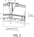
- FIG. 3 is an enlarged perspective view illustrating an example of the motor of the embodiment.
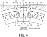
- FIG. 4 is an enlarged top view illustrating an example of the motor.
- FIG. 3 and FIG. 4 are enlarged views of the portion illustrated in a frame F 1 in FIG. 1 . Note that in FIG. 4 , the stator 10 is illustrated in a simplified manner.
- a magnetic gap G1 extending in the peripheral direction is formed in the radial direction between an inner peripheral surface 19 of the stator 10 and an outer peripheral surface 29 of the rotor 20 illustrated in FIG. 3 and FIG. 4 .
- the magnetic gap G1 includes a first portion formed between the stator 10 and a first wall 31 of the frame 39 of the rotor 20, a second portion formed between the stator 10 and the second magnet 42, and a third portion formed between the stator 10 and the third magnet 43.
- a radial width of the magnetic gap in the first portion is W1
- radial widths of the magnetic gap at the second portion and the third portion are W2.
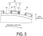
- FIG. 5 is an enlarged perspective view illustrating an example of the rotor according to the embodiment where magnets are removed.
- FIG. 5 illustrates a state before the first magnet 41, the second magnet 42, and the third magnet 43 are disposed to the rotor 20 illustrated in FIG. 4 .
- the second wall 32 and the third wall 33 are adjacent to the annular portion 36 in the radial direction and extend in the radial direction.
- the first wall 31 extends in the peripheral direction and is coupled to the annular portion 36 via the second wall 32 and the third wall 33 in the radial direction.
- the hole 38 is surrounded by a frame 39 including the first wall 31, the second wall 32, and the third wall 33.
- an engaging portion 34 is formed at a portion where the first wall 31 and the second wall 32 intersect with each other.
- an engaging portion 35 is formed at a portion where the first wall 31 and the third wall 33 intersect with each other.
- the engaging portion 35 is an example of other engaging portions.
- a corner portion of the second magnet 42 at or near a portion where a first surface 4a and a second surface 4b of the outer peripheral portion intersect with each other
- a corner portion of the third magnet 43 at or near a portion where the first surface and the second surface of the outer peripheral portion intersect with each other
- the second magnet 42 and the third magnet 43 oppose the first magnet 41.
- the second wall 32 is located between the first magnet 41 and the first surface 4a of the second magnet 42
- the third wall 33 is located between the first magnet 41 and the first surface 4c of the third magnet 43.
- the second magnet 42 opposes the first magnet 41 in the peripheral direction with the second wall 32 interposed.
- the third magnet 43 opposes the first magnet 41 in the peripheral direction with the third wall 33 interposed.
- the magnetic flux of the first magnet 41 is directed in a direction indicated by an arrow M1, for example, radially outward (the stator 10 side).
- the first wall 31 is positioned in the direction M1 with respect to the first magnet 41.
- the magnetic flux of the first magnet 41 is directed in the direction M1.
- the first wall 31 is disposed radially outward of the first magnet 41.
- a thickness T4 of a first wall 51 forming a frame 59 in the radial direction is smaller than the thickness T1 of the first wall 31 of the embodiment illustrated in FIG. 6 in the radial direction.
- the thickness T4 of the first wall 51 is preferably larger than thicknesses T5 of the second wall 52 and the third wall 53 in the peripheral direction.
- a first magnet 61 having a shape different from the shape of the first magnet 41 in the embodiment is disposed in a hole 58 surrounded by the frame 59.
- the first magnet 61 is surrounded by two second magnets 62 in the peripheral direction.
- the two second magnets 62 have substantially the same shape.
- Directions M8 and M9 of the magnetic fluxes of the two second magnets 62 are directed in directions opposite to each other.
- the motor 1 of the embodiment is an inner rotor motor, but no such limitation is intended.
- an outer rotor motor as illustrated in FIG. 8 may be employed.
- FIG. 8 is a perspective view illustrating an example of a motor of a second variation.
- FIG. 9 is an enlarged perspective view illustrating an example of the motor according to the second variation.
- FIG. 9 is an enlarged view of a portion illustrated in a frame F3 in FIG. 8 .
- a rotor 80 is disposed radially outward of a stator 70.
- an annular portion 86 of the rotor 80 is positioned radially outward of the magnet 40.
- the first magnet 41 is disposed in a frame 89 formed by a first wall 81, a second wall 82, and a third wall 83.
- the motor 2 of the second variation is also a flat motor as with the motor 1 of the embodiment, but no such limitation is intended.
- the length of the motor in the axial direction may be longer than the length in the radial direction.
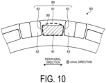
- a hole 98 surrounded by a frame 99 formed by a first wall 91, a second wall 92, and a third wall 93 has a shape with a radially outer surface curved in an arc shape.
- the first magnet 41 is disposed in the hole 98 of the third variation.
- the radially outer surface and the radially inner surface of the frame of the rotor and the first magnet may have different shapes from each other or may have substantially the same shape.
- the shape of the radially outer surface and the shape of the radially inner surface of the frame of the rotor may be different from each other as illustrated in FIG. 10 or may be substantially the same.
- the shape of the radially outer surface and the shape of the radially inner surface may be different from each other or may be substantially the same as illustrated in FIG. 11 .
Landscapes
- Engineering & Computer Science (AREA)
- Power Engineering (AREA)
- Permanent Field Magnets Of Synchronous Machinery (AREA)
Abstract
Description
- The present invention relates to a motor.
- There is known a so-called Halbach array motor where a plurality of magnets having different directions of magnetic flux are disposed at a surface of a rotor yoke. In the Halbach array motor, for example, in a motor having an inner rotor structure, a technique is known where a magnet is embedded in a magnet holding member to suppress jumping out of the magnet due to centrifugal force during rotation.
-
- Patent Document 1:
JP 2007-006545 A - Patent Document 2:
JP 2010-207067 A - Patent Document 3:
WO 2014/115655 - However, in the Halbach array motor, the amount of magnetic flux flowing from the magnet to the stator side may decrease. In this case, output torque of the motor decreases.
- In one aspect, an object is to provide a motor capable of improving the output torque.
- In one aspect, a motor includes: a rotor including a yoke, a first magnet, and a second magnet opposing the first magnet; and a stator. The yoke includes a hole and a frame surrounding the hole. The first magnet is disposed in the hole of the yoke. The second magnet includes a first surface opposing the frame of the yoke in a peripheral direction and a second surface opposing the stator in a radial direction.
- According to the one aspect, output torque can be improved.
-
-
FIG. 1 is a perspective view illustrating an example of a motor of an embodiment. -
FIG. 2 is an exploded perspective view illustrating an example of the motor of the embodiment. -
FIG. 3 is an enlarged perspective view illustrating an example of the motor of the embodiment. -
FIG. 4 is an enlarged top view illustrating an example of the motor of the embodiment. -
FIG. 5 is an enlarged perspective view illustrating an example of a rotor of the embodiment where a magnet is removed. -
FIG. 6 is an enlarged perspective view illustrating an example of the rotor of the embodiment. -
FIG. 7 is an enlarged top view illustrating an example of a rotor of a first variation. -
FIG. 8 is a perspective view illustrating an example of a motor of a second variation. -
FIG. 9 is an enlarged perspective view illustrating an example of the motor of the second variation. -
FIG. 10 is an enlarged top view illustrating an example of a rotor of a third variation. -
FIG. 11 is an enlarged top view illustrating an example of a rotor of a fourth variation. - An embodiment of a motor disclosed in the present application will be described below in detail with reference to the drawings. Note that dimensional relationships between elements and ratios of elements in the drawings may differ from actual configurations. The drawings may include parts having mutually different dimensional relationships and proportions. For the sake of clarity, a coordinate system with an extension direction of rotation axis of the motor defined as an axial direction may be used in the drawings.
- First, a motor of an embodiment will be described with reference to
FIG. 1 andFIG. 2 .FIG. 1 is a perspective view illustrating an example of the motor of the embodiment.FIG. 2 is an exploded perspective view illustrating an example of the motor of the embodiment. As illustrated inFIG. 1 , amotor 1 of the embodiment includes astator 10 and arotor 20. Themotor 1 of the embodiment is a so-called flat motor, for example. In the flat motor, the length of a stator core in the radial direction is larger than the length of the stator core in the axial direction. Themotor 1 is accommodated in a frame (not illustrated), for example, and transmits driving force to the outside through a rotation axis (not illustrated). - As illustrated in
FIG. 2 , thestator 10 includes astator core 11, aninsulator 12, and acoil 13. Thestator core 11 is formed by stacking, in an axial direction, a plurality of plate-shaped metal members or magnetic bodies such as silicon steel plates, electromagnetic steel plates, or soft magnetic steel plates, for example. Theinsulators 12 is formed of an insulation body such as resin, for example, and mounted to thestator core 11 from the positive direction side and the negative direction side in the axial direction. Thecoil 13 is wound around thestator core 11 via theinsulator 12. As illustrated inFIG. 2 ,end portions 14 of the conducting wire are drawn from thecoil 13 in the same direction (positive direction side in the axial direction) as draw wires. Theend portions 14 of the conducting wire are used as terminals of thecoil 13, for example. - As illustrated in
FIG. 1 andFIG. 2 , therotor 20 is disposed at the inner peripheral side of thestator 10 in the radial direction. That is, themotor 1 of the embodiment is an inner rotor motor. As illustrated inFIG. 2 , therotor 20 includes ayoke 30 forming a magnetic path, a plurality offirst magnets 41, a plurality ofsecond magnets 42, and a plurality ofthird magnets 43. Note that in the following, thefirst magnet 41 to thethird magnet 43 may be referred to as amagnet 40 when expressed without distinction. Thefirst magnet 41 may be referred to as a main magnet, and thesecond magnet 42 and thethird magnet 43 may be referred to as auxiliary magnets. In the embodiment, two types ofauxiliary magnets main magnet 41. - The
yoke 30 is a yoke formed of iron, for example, and includes anannular portion 36, ahole 38, and aframe 39 surrounding thehole 38. Theyoke 30 includes a plurality ofholes 38 and a plurality offrames 39. As illustrated inFIG. 2 , theannular portion 36 extends in the peripheral direction. The plurality offrames 39 are formed and aligned at equal intervals in the peripheral direction, for example. Note that in the following embodiment and variations, the material of the yoke is not limited to iron but may be other magnetic bodies. - The
first magnet 41 is disposed in thehole 38 surrounded by theframe 39, and thesecond magnet 42 and thethird magnet 43 are disposed between twoframes 39 adjacent to each other in the peripheral direction. In the embodiment, twoauxiliary magnets frames 39 adjacent to each other in the peripheral direction. - In the embodiment, the
second magnet 42 and thethird magnet 43 have substantially the same shape but have different directions of magnetic flux as will be described later. Thesecond magnet 42 and thethird magnet 43 are disposed laterally symmetrically with respect to a straight line L1, illustrated inFIG. 4 , connecting the center of thefirst magnet 41 in the peripheral direction and the center of therotor 20.FIG. 3 is an enlarged perspective view illustrating an example of the motor of the embodiment.FIG. 4 is an enlarged top view illustrating an example of the motor.FIG. 3 andFIG. 4 are enlarged views of the portion illustrated in aframe F 1 inFIG. 1 . Note that inFIG. 4 , thestator 10 is illustrated in a simplified manner. - As illustrated in
FIG. 4 , a magnetic gap G1 extending in the peripheral direction is formed in the radial direction between an innerperipheral surface 19 of thestator 10 and an outerperipheral surface 29 of therotor 20 illustrated inFIG. 3 andFIG. 4 . The magnetic gap G1 includes a first portion formed between thestator 10 and afirst wall 31 of theframe 39 of therotor 20, a second portion formed between thestator 10 and thesecond magnet 42, and a third portion formed between thestator 10 and thethird magnet 43. As illustrated inFIG. 4 , a radial width of the magnetic gap in the first portion is W1, and radial widths of the magnetic gap at the second portion and the third portion are W2. - As illustrated in
FIG. 4 , thesecond magnet 42 is adjacent to a side surface of theannular portion 36 at the magnetic gap G1 side in the radial direction, for example, a side surface S1 at the outer side in the radial direction. Thethird magnet 43 is also adjacent to the side surface S1 of theannular portion 36. - As illustrated in
FIG. 5 , theframe 39 of theyoke 30 is formed by thefirst wall 31, asecond wall 32, and athird wall 33.FIG. 5 is an enlarged perspective view illustrating an example of the rotor according to the embodiment where magnets are removed.FIG. 5 illustrates a state before thefirst magnet 41, thesecond magnet 42, and thethird magnet 43 are disposed to therotor 20 illustrated inFIG. 4 . - As illustrated in
FIG. 5 , in the embodiment, thesecond wall 32 and thethird wall 33 are adjacent to theannular portion 36 in the radial direction and extend in the radial direction. Thefirst wall 31 extends in the peripheral direction and is coupled to theannular portion 36 via thesecond wall 32 and thethird wall 33 in the radial direction. Thehole 38 is surrounded by aframe 39 including thefirst wall 31, thesecond wall 32, and thethird wall 33. - As illustrated in
FIG. 6 , thefirst magnet 41 accommodated in thehole 38 is positioned between thefirst wall 31 and theannular portion 36 in the radial direction.FIG. 6 is an enlarged perspective view illustrating an example of the rotor of the embodiment.FIG. 6 is an enlarged view of a portion illustrated in a frame F3 inFIG. 3 . - As illustrated in
FIG. 6 , in the embodiment, a thickness T1 of thefirst wall 31 in the radial direction is larger than a thickness T2 of thesecond wall 32 in the peripheral direction. In the embodiment, the thickness of thethird wall 33 in the peripheral direction is substantially the same as the thickness T2 of thesecond wall 32. That is, the thickness T1 of thefirst wall 31 is larger than the thickness of thethird wall 33 in the peripheral direction. - As illustrated in
FIG. 5 andFIG. 6 , in theframe 39, an engagingportion 34 is formed at a portion where thefirst wall 31 and thesecond wall 32 intersect with each other. Similarly, in theframe 39, an engagingportion 35 is formed at a portion where thefirst wall 31 and thethird wall 33 intersect with each other. Note that the engagingportion 35 is an example of other engaging portions. In the illustrated example, a corner portion of the second magnet 42 (at or near a portion where afirst surface 4a and asecond surface 4b of the outer peripheral portion intersect with each other) and a corner portion of the third magnet 43 (at or near a portion where the first surface and the second surface of the outer peripheral portion intersect with each other) are engaged portions with respect to the engagingportion 34 and the engagingportion 35, respectively. The engagingportions portions second magnet 42 and thethird magnet 43. The engagingportions second magnet 42 and thethird magnet 43. - As illustrated in
FIG. 4 andFIG. 6 , thesecond magnet 42 includes thefirst surface 4a and thesecond surface 4b. Thefirst surface 4a opposes theframe 39 of theyoke 30 in the peripheral direction. In an example, thefirst surface 4a opposes thesecond wall 32 of theframe 39. For example, in the embodiment, thefirst surface 4a is in contact with thesecond wall 32 of theframe 39 in the peripheral direction. Thesecond surface 4b opposes thestator 10 in the radial direction. Similarly, as illustrated inFIG. 4 , thethird magnet 43 includes afirst surface 4c opposing thethird wall 33 of theframe 39 and asecond surface 4d opposing thestator 10. In an example, thesecond surface 4b of thesecond magnet 42 directly opposes thestator 10 via the magnetic gap G1 in the radial direction, and thesecond surface 4d of thethird magnet 43 directly opposes thestator 10 via the magnetic gap G1 in the radial direction. - In the embodiment, the
second magnet 42 and thethird magnet 43 oppose thefirst magnet 41. In the peripheral direction, thesecond wall 32 is located between thefirst magnet 41 and thefirst surface 4a of thesecond magnet 42, and thethird wall 33 is located between thefirst magnet 41 and thefirst surface 4c of thethird magnet 43. For example, as illustrated inFIG. 4 andFIG. 6 , thesecond magnet 42 opposes thefirst magnet 41 in the peripheral direction with thesecond wall 32 interposed. As illustrated inFIG. 4 , thethird magnet 43 opposes thefirst magnet 41 in the peripheral direction with thethird wall 33 interposed. - Returning to
FIG. 4 , the magnetic flux of thefirst magnet 41 is directed in a direction indicated by an arrow M1, for example, radially outward (thestator 10 side). In the embodiment, thefirst wall 31 is positioned in the direction M1 with respect to thefirst magnet 41. The magnetic flux of thefirst magnet 41 is directed in the direction M1. In an example, thefirst wall 31 is disposed radially outward of thefirst magnet 41. Such a configuration suppresses jumping out of thefirst magnet 41 from therotor 20 due to a centrifugal force or a repulsive force of the magnet during rotation of therotor 20. - The magnetic flux of the
second magnet 42 is directed in a direction M2 inclined in the peripheral direction with respect to the direction M1 of the magnetic flux of the first magnet. Similarly, a direction M3 of the magnetic flux of thethird magnet 43 is directed in the direction M3 inclined in the peripheral direction with respect to the direction M1 of the magnetic flux of thefirst magnet 41. The direction M3 is different from the direction M2 of the magnetic flux of the second magnet. - Furthermore, the
second magnet 42 engages with the engagingportion 34, and thethird magnet 43 engages with the engagingportion 35. In an example, as illustrated inFIG. 4 andFIG. 6 , the engagingportion 34 is disposed in accordance with the direction M2 of the magnetic flux of thesecond magnet 42. The engagingportion 35 is disposed in accordance with the direction M3 of the magnetic flux of thethird magnet 43. In the embodiment, the engagingportion 34 is disposed radially outward of the second magnet, and the engagingportion 35 is disposed radially outward of the third magnet. Such a configuration suppresses jumping out of thesecond magnet 42 and thethird magnet 43 from therotor 20 due to a centrifugal force or a repulsive force of the magnet during rotation of therotor 20. - No magnetic body is disposed at each of the
second surfaces second magnet 42 and thethird magnet 43. In other words, theyoke 30 is not disposed radially outward of thesecond magnet 42 and thethird magnet 43. Each of thesecond magnet 42 and thethird magnet 43 directly opposes thestator 10 in the radial direction. Accordingly, the magnetic flux of thesecond magnet 42 and thethird magnet 43 easily flows to thestator 10, and the circulation of the magnetic flux between thesecond magnet 42 and thethird magnet 43 is suppressed. - As illustrated in
FIG. 4 andFIG. 6 , by increasing the width T1 of thefirst wall 31 of theyoke 30, the radially outer surface of the first magnet is positioned radially inward of thesecond surface 4b of thesecond magnet 42 and thesecond surface 4d of thethird magnet 43. Accordingly, the circulation of the magnetic flux by thesecond magnet 42 and thethird magnet 43 is suppressed, and thus the magnetic flux flowing to thestator 10 is increased. By reducing the thickness of thesecond wall 32 and thethird wall 33 in the peripheral direction, thesecond wall 32 and thethird wall 33 are magnetically saturated. Thus, the circulation of the magnetic flux by thesecond magnet 42 and thethird magnet 43 is suppressed, and the magnetic flux flowing to thestator 10 is further increased. - As described above, the
motor 1 of the embodiment includes: therotor 20 including theyoke 30, thefirst magnet 41, and thesecond magnet 42 adjacent to thefirst magnet 41; and thestator 10. Theyoke 30 includes thehole 38 and theframe 39 surrounding thehole 38. Thefirst magnet 41 is disposed in thehole 38 of theyoke 30. Thesecond magnet 42 includes thefirst surface 4a opposing theframe 39 of theyoke 30 in the peripheral direction and thesecond surface 4b opposing thestator 10 in the radial direction. Such a configuration increases the magnetic flux flowing from themagnets 41 to 43 to thestator 10, and thus can improve the output torque. - The configuration according to the embodiment has been described above, but embodiments are not limited to this embodiment. For example, although the configuration including the two types of
auxiliary magnets FIG. 7 , a configuration including only one type of auxiliary magnet may be employed. The relationship between the thickness of thefirst wall 31 and the thicknesses of thesecond wall 32 and thethird wall 33 in theframe 39 of the embodiment is not limited to the relationship illustrated inFIG. 6 .FIG. 7 is an enlarged top view illustrating an example of a rotor of a first variation. Note that in the following variations, the same components as the components illustrated in the above-described drawings are denoted with the same reference signs, and overlapping descriptions will be omitted. - As illustrated in
FIG. 7 , in arotor 50 of the first variation, a thickness T4 of afirst wall 51 forming aframe 59 in the radial direction is smaller than the thickness T1 of thefirst wall 31 of the embodiment illustrated inFIG. 6 in the radial direction. Note that also in this case, the thickness T4 of thefirst wall 51 is preferably larger than thicknesses T5 of thesecond wall 52 and thethird wall 53 in the peripheral direction. - As illustrated in
FIG. 7 , in the first variation, afirst magnet 61 having a shape different from the shape of thefirst magnet 41 in the embodiment is disposed in ahole 58 surrounded by theframe 59. In the first variation, thefirst magnet 61 is surrounded by twosecond magnets 62 in the peripheral direction. In the first variation, the twosecond magnets 62 have substantially the same shape. Directions M8 and M9 of the magnetic fluxes of the twosecond magnets 62 are directed in directions opposite to each other. - In the configuration including the
first magnet 61 and thesecond magnet 62 as illustrated inFIG. 7 , manufacturing is easy. On the other hand, in the configuration including thefirst magnet 41, thesecond magnet 42, and thethird magnet 43 as illustrated inFIG. 4 , the influence of demagnetization can be reduced. By increasing the size of thefirst magnet 61, the magnetic flux flowing from thefirst magnet 61 to thestator 10 can be increased. - The
motor 1 of the embodiment is an inner rotor motor, but no such limitation is intended. For example, an outer rotor motor as illustrated inFIG. 8 may be employed.FIG. 8 is a perspective view illustrating an example of a motor of a second variation.FIG. 9 is an enlarged perspective view illustrating an example of the motor according to the second variation.FIG. 9 is an enlarged view of a portion illustrated in a frame F3 inFIG. 8 . - As illustrated in
FIG. 8 , in amotor 2 of the second variation, arotor 80 is disposed radially outward of astator 70. As illustrated inFIG. 9 , in theouter rotor motor 2, anannular portion 86 of therotor 80 is positioned radially outward of themagnet 40. For example, thefirst magnet 41 is disposed in aframe 89 formed by afirst wall 81, asecond wall 82, and athird wall 83. - In this case, the
magnet 40 is less likely to jump out due to centrifugal force. However, as in the embodiment, the amount of magnetic flux can be increased by making the thickness of thefirst wall 81 in the radial direction thicker than the thicknesses of thesecond wall 82 and thethird wall 83 in the peripheral direction and providing therotor 80 with engagingportions - Note that the
motor 2 of the second variation is also a flat motor as with themotor 1 of the embodiment, but no such limitation is intended. In both the inner rotor motor and the outer rotor motor, the length of the motor in the axial direction may be longer than the length in the radial direction. - Furthermore, in the embodiment, the configuration where both the shape of the
hole 38 and the shape of thefirst magnet 41 are substantially rectangular has been described, but the embodiment is not limited to the configuration. For example, the hole and the magnet may be formed to include a curved shape. As illustrated inFIG. 10 andFIG. 11 , a rectangular magnet may be accommodated in a hole including a curved shape, or a magnet including a curved shape may be accommodated in a hole formed in a rectangular shape.FIG. 10 is an enlarged top view illustrating an example of a rotor of a third variation.FIG. 11 is an enlarged top view illustrating an example of a rotor of a fourth variation. - As illustrated in
FIG. 10 , in arotor 90 of the third variation, ahole 98 surrounded by aframe 99 formed by afirst wall 91, asecond wall 92, and athird wall 93 has a shape with a radially outer surface curved in an arc shape. As in the embodiment, thefirst magnet 41 is disposed in thehole 98 of the third variation. - As illustrated in
FIG. 11 , in the fourth variation, afirst magnet 69 is disposed in thehole 58 of therotor 50 as in the first variation. Thefirst magnet 69 is different from thefirst magnet 41 of the embodiment and thefirst magnet 61 of the first variation in that both the radially outer surface and the radially inner surface are curved in an arc shape. - As described above, the radially outer surface and the radially inner surface of the frame of the rotor and the first magnet may have different shapes from each other or may have substantially the same shape. The shape of the radially outer surface and the shape of the radially inner surface of the frame of the rotor may be different from each other as illustrated in
FIG. 10 or may be substantially the same. Similarly, in the first magnet, the shape of the radially outer surface and the shape of the radially inner surface may be different from each other or may be substantially the same as illustrated inFIG. 11 . - An embodiment and variations of the present invention have been described above. However, the present invention is not limited to the embodiment and the variations and can be variously modified without departing from the gist of the present invention. Various modifications within a scope not departing from the gist are also included in the technical scope of the present invention, and this is obvious to a person having skill in the art from the description of the claims.
- 1, 2 Motor, 10, 70 Stator, 11 Stator core, 12 Insulator, 13 Coil, 14 End portion of conducting wire, 20, 50, 80, 90 Rotor, 30 Yoke, 31, 51, 81, 91 First wall, 32, 52, 82, 92 Second wall, 33, 53, 83, 93 Third wall, 34, 35, 84, 85 Rib (engaging portion), 36, 86 Annular portion, 38, 58, 98 Hole, 39, 59, 89, 99 Frame, 41, 61, 69 First magnet, 42, 62 Second magnet, 43 Third magnet, G1 Magnetic gap
Claims (12)
- A motor comprising:a rotor including a yoke, a first magnet, and a second magnet opposing the first magnet; anda stator, whereinthe yoke includes a hole and a frame surrounding the hole,the first magnet is disposed in the hole of the yoke, andthe second magnet includes a first surface opposing the frame of the yoke in a peripheral direction and a second surface opposing the stator in a radial direction.
- The motor according to claim 1, whereinthe frame includes a first wall, a second wall, and a third wall,the yoke includes an annular portion adjacent to the second wall and the third wall in the radial direction, andthe first magnet is located between the first wall and the annular portion in the radial direction.
- The motor according to claim 2, wherein
a width of the first wall in the radial direction is larger than a width of the second wall or a width of the third wall in the peripheral direction. - The motor according to claim 2 or 3, wherein
the second wall is located between the first magnet and the first surface of the second magnet in the peripheral direction. - The motor according to any one of claims 2 to 4, comprising a magnetic gap extending in the peripheral direction, whereina first portion of the magnetic gap is formed by the first wall and the stator in the radial direction,a second portion of the magnetic gap is formed by the second surface of the second magnet and the stator in the radial direction, andthe second magnet is in contact with a side surface of the annular portion at a side of the magnetic gap in the radial direction.
- The motor according to any one of claims 2 to 5, whereinan engaging portion is provided at a portion where the second wall and the first wall intersect with each other, andthe second magnet is engaged with the engaging portion.
- The motor according to any one of claims 2 to 6, whereina direction of a magnetic flux of the first magnet is directed in a radial direction, anda direction of a magnetic flux of the second magnet is directed in a direction inclined in the peripheral direction with respect to the direction of the magnetic flux of the first magnet.
- The motor according to any one of claims 2 to 7, whereinthe rotor includes a third magnet opposing the first magnet, andthe third magnet includes a first surface opposing the frame of the yoke in the peripheral direction and a second surface opposing the stator in the radial direction.
- The motor according to claim 8, wherein
in the peripheral direction, the first magnet is located between the second magnet and the third magnet, and the third wall is located between the first magnet and the first surface of the third magnet. - The motor according to claim 8 or 9, comprising a magnetic gap extending in the peripheral direction, whereina third portion of the magnetic gap is formed by the second surface of the third magnet and the stator in the radial direction, andthe third magnet is in contact with a side surface of the annular portion at a side of the magnetic gap.
- The motor according to any one of claims 8 to 10, whereinan other engaging portion is provided at a portion where the third wall and the first wall intersect with each other, andthe third magnet is engaged with the other engaging portion.
- The motor according to any one of claims 8 to 11, whereina direction of a magnetic flux of the first magnet is directed in the radial direction, anda direction of a magnetic flux of the third magnet is directed in a direction inclined in the peripheral direction with respect to the direction of the magnetic flux of the first magnet, the direction of the magnetic flux of the third magnet being different from a direction of a magnetic flux of the second magnet.
Applications Claiming Priority (1)
| Application Number | Priority Date | Filing Date | Title |
|---|---|---|---|
| PCT/JP2021/031982 WO2023032040A1 (en) | 2021-08-31 | 2021-08-31 | Motor |
Publications (2)
| Publication Number | Publication Date |
|---|---|
| EP4398457A1 true EP4398457A1 (en) | 2024-07-10 |
| EP4398457A4 EP4398457A4 (en) | 2025-06-25 |
Family
ID=85412387
Family Applications (1)
| Application Number | Title | Priority Date | Filing Date |
|---|---|---|---|
| EP21955931.7A Pending EP4398457A4 (en) | 2021-08-31 | 2021-08-31 | MOTOR |
Country Status (6)
| Country | Link |
|---|---|
| US (1) | US20240356399A1 (en) |
| EP (1) | EP4398457A4 (en) |
| JP (1) | JP7827733B2 (en) |
| CN (1) | CN117795824A (en) |
| TW (1) | TW202312627A (en) |
| WO (1) | WO2023032040A1 (en) |
Family Cites Families (35)
| Publication number | Priority date | Publication date | Assignee | Title |
|---|---|---|---|---|
| DE4039320A1 (en) * | 1990-12-10 | 1992-06-11 | Kloeckner Humboldt Deutz Ag | Magnet system for magnetic separator - comprises ring of magnetic blocks with varying magnetisation directions |
| JP3308828B2 (en) * | 1996-10-18 | 2002-07-29 | 株式会社日立製作所 | Permanent magnet rotating electric machine and electric vehicle using the same |
| JP2002354721A (en) * | 2001-05-29 | 2002-12-06 | Hitachi Ltd | Rotating electric machine with permanent magnet type rotor |
| JP2004350427A (en) * | 2003-05-22 | 2004-12-09 | Denso Corp | Rotating electric machine and its rotor |
| JP4796788B2 (en) * | 2005-05-10 | 2011-10-19 | 株式会社日立製作所 | Coreless motor |
| JP2007006545A (en) | 2005-06-21 | 2007-01-11 | Yaskawa Electric Corp | Periodic magnetic field generator and linear motor, rotary motor, swing motor using the same |
| JP2010207067A (en) | 2009-03-06 | 2010-09-16 | Hyundai Motor Co Ltd | Magnet-embedded rotor |
| CN102157998B (en) * | 2011-03-25 | 2013-07-17 | 上海大学 | Rotor of built-in permanent magnet motor and magnetic steel structural parameter determining method thereof |
| CN103534900B (en) * | 2011-07-08 | 2016-01-20 | 三菱电机株式会社 | Permanet magnet type rotary electric machine and manufacture method thereof |
| DE112012006031A5 (en) * | 2012-03-13 | 2015-02-26 | Brose Fahrzeugteile GmbH & Co. Kommanditgesellschaft, Würzburg | Electric machine |
| DE112012006417T5 (en) * | 2012-05-22 | 2015-02-26 | Mitsubishi Electric Corporation | Electric rotary machine with embedded permanent magnet |
| DE112014000526B4 (en) | 2013-01-23 | 2018-03-01 | Mitsubishi Electric Corporation | Rotor and rotating electrical machine containing this rotor |
| US9800102B2 (en) * | 2013-03-06 | 2017-10-24 | Asmo Co., Ltd. | Dual rotor core motor with reduced flux leakage |
| JP6278333B2 (en) * | 2013-09-03 | 2018-02-14 | アイシン精機株式会社 | Electric motor |
| US10491069B2 (en) * | 2014-09-16 | 2019-11-26 | Greentech Motors Corporation | Electric motor with laminated sheet windings |
| JP6417207B2 (en) * | 2014-12-19 | 2018-10-31 | マブチモーター株式会社 | motor |
| JP6409607B2 (en) * | 2015-02-18 | 2018-10-24 | 株式会社デンソー | Rotating electric machine |
| CN106357073B (en) * | 2016-10-10 | 2018-11-09 | 江苏大学 | High winding coefficient permanent magnetic brushless and its design and fault tolerant control method |
| CN106849409B (en) * | 2016-11-11 | 2020-10-30 | 南方电机科技有限公司 | Motor comprising HALBACH array and equipment comprising motor |
| US11239715B2 (en) * | 2017-08-30 | 2022-02-01 | Kogakuin University | Electromagnetic device |
| CN110504773B (en) * | 2018-05-17 | 2022-02-01 | 无锡小天鹅电器有限公司 | Rotor, motor and washing machine with same and manufacturing method of rotor |
| CN108736608B (en) * | 2018-07-04 | 2024-04-12 | 中国电子科技集团公司第二十一研究所 | Halbach motor rotor structure and manufacturing method thereof |
| US11196310B2 (en) * | 2018-07-30 | 2021-12-07 | Zunum Aero, Inc. | Permanent magnet assemblies for a cylinder of an electrical machine |
| CN111130240A (en) * | 2018-10-30 | 2020-05-08 | 法雷奥日本株式会社 | Rotor and IPM motor using same |
| JP2020072634A (en) * | 2018-10-30 | 2020-05-07 | 株式会社ヴァレオジャパン | Rotor and IPM motor using the same |
| JP7623097B6 (en) * | 2018-11-29 | 2025-02-21 | 東芝ライフスタイル株式会社 | Manufacturing method of rotor magnet |
| JP2020202654A (en) * | 2019-06-10 | 2020-12-17 | 株式会社デンソー | Rotator and rotary electric machine |
| JP7234864B2 (en) * | 2019-08-26 | 2023-03-08 | 株式会社デンソー | Rotating electric machine and manufacturing method of rotating electric machine |
| JP7388071B2 (en) * | 2019-09-11 | 2023-11-29 | 株式会社デンソー | wheel drive device |
| JP7601396B2 (en) * | 2019-09-20 | 2024-12-17 | 学校法人 工学院大学 | Magnetic field generating device and rotating electric machine |
| JP2021083223A (en) * | 2019-11-19 | 2021-05-27 | 大銀微系統股▲分▼有限公司Hiwin Mikrosystem Corp. | Rotor structure of permanent magnet type motor |
| US11245317B2 (en) * | 2019-12-05 | 2022-02-08 | Whirlpool Corporation | Direct drive electric motor having stator and magnet configurations for improved torque capability |
| CN115280642B (en) * | 2020-03-18 | 2025-10-03 | 日本电产株式会社 | motor |
| CN112002545B (en) * | 2020-08-27 | 2021-10-26 | 包头市英思特稀磁新材料股份有限公司 | Assembling process of Halbach magnetic ring assembly |
| WO2023053601A1 (en) * | 2021-09-30 | 2023-04-06 | 日本電産株式会社 | Rotor and rotating electrical machine |
-
2021
- 2021-08-31 CN CN202180101400.XA patent/CN117795824A/en active Pending
- 2021-08-31 EP EP21955931.7A patent/EP4398457A4/en active Pending
- 2021-08-31 WO PCT/JP2021/031982 patent/WO2023032040A1/en not_active Ceased
- 2021-08-31 US US18/684,988 patent/US20240356399A1/en active Pending
- 2021-08-31 JP JP2023544841A patent/JP7827733B2/en active Active
-
2022
- 2022-08-16 TW TW111130818A patent/TW202312627A/en unknown
Also Published As
| Publication number | Publication date |
|---|---|
| TW202312627A (en) | 2023-03-16 |
| JP7827733B2 (en) | 2026-03-10 |
| JPWO2023032040A1 (en) | 2023-03-09 |
| WO2023032040A1 (en) | 2023-03-09 |
| EP4398457A4 (en) | 2025-06-25 |
| US20240356399A1 (en) | 2024-10-24 |
| CN117795824A (en) | 2024-03-29 |
Similar Documents
| Publication | Publication Date | Title |
|---|---|---|
| CN105052015B (en) | Axial Rotary Motor | |
| CN103339831B (en) | rotor for motor | |
| US8957561B2 (en) | Rotor for rotary electric machine | |
| US9800096B2 (en) | Interior permanent magnet synchronous motor with optimized thicknesses and sectional areas | |
| US20170117765A1 (en) | Permanent magnet rotor for synchronous electric motor | |
| JP7017642B2 (en) | Rotor structure, permanent magnet assisted synchronous reluctance motor and electric vehicle | |
| US12261485B2 (en) | Rotor with permanent magnets having different coercive forces | |
| JP6112970B2 (en) | Permanent magnet rotating electric machine | |
| US6819015B2 (en) | Stator fastening structure of reciprocating motor | |
| EP2676353A2 (en) | Split core and stator core | |
| JP2011172359A (en) | Split rotor and electric motor | |
| CN108475946B (en) | Stator for rotating electric machine, and method for manufacturing stator for rotating electric machine | |
| CN106063085B (en) | Rotor | |
| JP2011244689A (en) | Manufacturing method of electric motor and split stator iron core | |
| US20240356399A1 (en) | Motor | |
| EP3748815B1 (en) | Dynamo-electric machine and stator | |
| JP7038527B2 (en) | Manufacturing method of magnetic wedge for rotary electric machine, magnetic wedge for rotary electric machine, and rotary electric machine | |
| JP2023049509A (en) | rotor and motor | |
| US12136854B2 (en) | Rotating electrical machine | |
| JP2001197689A (en) | Motor stator | |
| US20240235294A9 (en) | Rotating electrical machine | |
| US20240396383A1 (en) | Electric motor stator, electric motor, and method for manufacturing electric motor stator | |
| KR20230113984A (en) | Motor | |
| JP2023087340A (en) | motor |
Legal Events
| Date | Code | Title | Description |
|---|---|---|---|
| STAA | Information on the status of an ep patent application or granted ep patent |
Free format text: STATUS: THE INTERNATIONAL PUBLICATION HAS BEEN MADE |
|
| PUAI | Public reference made under article 153(3) epc to a published international application that has entered the european phase |
Free format text: ORIGINAL CODE: 0009012 |
|
| STAA | Information on the status of an ep patent application or granted ep patent |
Free format text: STATUS: REQUEST FOR EXAMINATION WAS MADE |
|
| 17P | Request for examination filed |
Effective date: 20240308 |
|
| AK | Designated contracting states |
Kind code of ref document: A1 Designated state(s): AL AT BE BG CH CY CZ DE DK EE ES FI FR GB GR HR HU IE IS IT LI LT LU LV MC MK MT NL NO PL PT RO RS SE SI SK SM TR |
|
| P01 | Opt-out of the competence of the unified patent court (upc) registered |
Free format text: CASE NUMBER: APP_52555/2024 Effective date: 20240919 |
|
| DAV | Request for validation of the european patent (deleted) | ||
| DAX | Request for extension of the european patent (deleted) | ||
| A4 | Supplementary search report drawn up and despatched |
Effective date: 20250522 |
|
| RIC1 | Information provided on ipc code assigned before grant |
Ipc: H02K 21/16 20060101ALI20250516BHEP Ipc: H02K 1/2783 20220101ALI20250516BHEP Ipc: H02K 1/276 20220101ALI20250516BHEP Ipc: H02K 1/22 20060101AFI20250516BHEP |